

Bryant 912SC Product Data
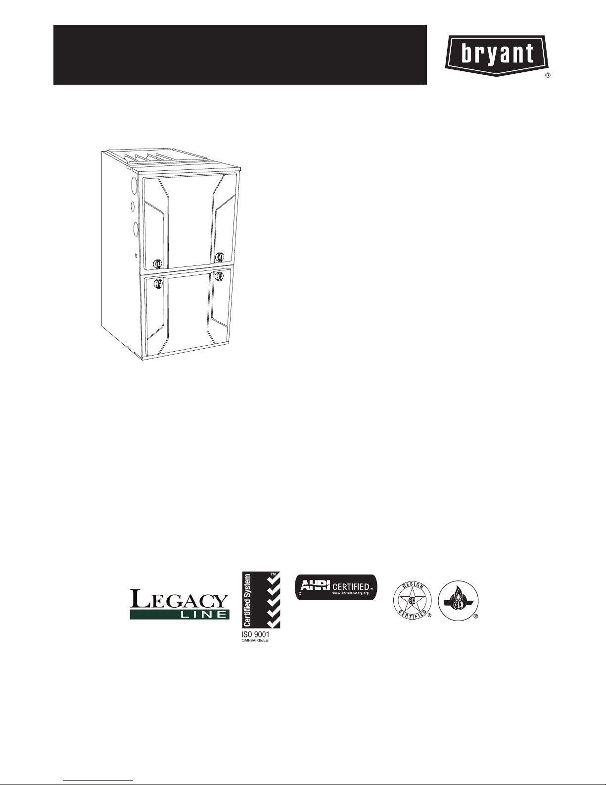
912SC 92.1 AFUE
LEGACYt LINE SINGLE--STAGE
4--WAY MULTIPOISE
CONDENSING GAS FURNACE, SERIES A
Product Data
A11264
The 912S Multipoise Condensing Gas Furnace is part of the
Legacyt Line product offering. Sporting a PSC blower motor
and an Annual Fuel Utilization Efficiency (AFUE) of 92.1%, this
single-stage gas furnace provides efficient comfort for
homeowners. This Legacy Line Gas Furnace also features 4-way
multipoise installation flexibility, and is available in eight model
sizes. The 912S can be vented for direct vent/two-pipe, ventilated
combustion air, or single-pipe applications. A BryantR Air
Conditioner or Heat Pump can be used to form a complete system.
All units meet California Air Quality Management District
emission requirements. These furnaces are approved for
Manufactured Housing (Mobile Home) applications. All sizes are
design certified in Canada.
STANDARD FEATURES
S 4-way multipoise design for upflow, downflow or horizontal
installation.
S Optional through-the-cabinet downflow venting.
S Installation flexibility with a 360-degree rotating elbow.
S Ideal condensing furnace height 35” cabinet: short enough for
taller coils, but still allows enough room for service.
S Silicon Nitride Perfect Lightt Hot Surface Igniter.
S Aluminized-steel primary heat exchanger.
S Stainless-steel condensing secondary heat exchanger.
S High-quality corrosion-resistant prepainted steel cabinet with
hemmed edges for safety.
S Factory-configured ready for upflow applications.
S Direct-vent/sealed combustion, single-pipe venting or ventilated
combustion air.
S PSC blower motor, single-speed inducer motor, and single-stage
gas valve.
S Self-diagnostics
S Approved for Twinning applications (36060 through 60120
sizes, only).
S Propane convertible (See accessory list).
S Approved for Manufactured Housing/Mobile Home applications
with MH accessory kit.
S Convenient Air Purifier and Humidifier electrical connections.
S Residential installations may be eligible for consumer financing
through the Retail Credit Program.
S Certified to leak 2% or less of nominal air conditioning CFM
delivered when pressurized to 1-inch water column with all
present air inlets, air outlets, and condensate drain port(s) are
sealed.
Use of the AHRI Certified TM Mark indicates a
manufacturer’s participation in the program. For
verification of certification for individual products,
go to www.ahridirectory.org.
1
CERTIFIED

CASING
DIMENSIONS
SAP ORDERING NO.
912SC30040S14 35 29.5 14.2 37,000 92.1% 910 0.10 595--- 970 1/3 - 4
912SC36040S17 35 29.5 17.5 37,000 92.1% 980 0.10 655--- 1140 1/2 - 5
912SC36060S14 35 29.5 14.2 56,000 92.1% 910 0.12 645--- 1155 1/3 - 4
912SC48060S17 35 29.5 17.5 56,000 92.1% 980 0.12 985--- 1505 1/2 - 4
912SC48080S17 35 29.5 17.5 75,000 92.1% 1030 0.15 760--- 1555 1/2 - 5
912SC60080S21 35 29.5 21.0 75,000 92.1% 1115 0.15 865--- 1885 3/4 - 5
912SC48100S21 35 29.5 21.0 93,000 92.1% 1490 0.20 890--- 1490 1/2 - 4
912SC60100S21 35 29.5 21.0 93,000 92.1% 1550 0.20 1475--- 1970 3/4 - 4
912SC60120S24 35 29.5 24.5 112,000 92.1% 2070 0.20 1450--- 2050 3/4 - 4
† Capacity in accordance with DOE test procedures. Ratings are position dependent. See rating plate.
‡ Heating CFM at factory default blower motor heating tap settings.
ESP --- External Static Pressure
(IN.)
H D W (BTUH) AFUE CFM‡
RATED
HEATING
OUTPUT†
HEATING
AIRFLOW
Heating
ESP
(in. W.C.)
COOLING CFM @ 0.5 ESP
(in. W.C.)
MOTOR HP -
SPEED TAPS
FEATURES AND BENEFITS
HYBRID HEATR Dual Fuel system — This system can provide
912SC
more control over your monthly energy bills by automatically
selecting the most economical method of heating. With HYBRID
HEAT, our system automatically switches between the gas furnace
and the single--stage electric heat pump as outside temperatures
change to maintain greater efficiency and comfort than with any
traditional single-source heating system. The heat pump also
delivers high-efficiency cooling in the summer.
Power Heatt Igniter — Bryant’s unique SiN igniter is not only
physically robust but it is also electrically robust. It is capable of
running at line voltage and does not require complex voltage
regulators as do other brands. This unique feature further enhances
the gas furnace reliability and continues Bryant’s tradition of
technology leadership and innovation in providing a reliable and
durable product.
Reliable Heat Exchanger Design — The aluminized steel, clam
shell primary heat exchanger was re--engineered to achieve greater
efficiency out of a smaller size. The first two passes of the heat
exchanger are based on the current 80% product, a design with
more than ten years of field-proven performance and success.
These innovations, paired with the continuation of a crimped,
no-weld seam create an efficient, robust design for this essential
component.
The condensing heat exchanger, a stainless steel fin and tube
design, is positioned in the furnace to extract additional heat.
Stainless steel coupling box componentry between heat exchangers
has exceptional corrosion resistance in both natural gas and
propane applications.
4-Way Multipoise Design — One model for all applications –
there is no need to stock special downflow or horizontal models
when one unit will do it all. The new heat exchanger design allows
these units to achieve the certified AFUE in all positions.
Direct or Single-pipe Venting, or Optional Ventilated
Combustion Air — This furnace can be installed as a 2-pipe
(Direct Vent) furnace, in an optional ventilated combustion air
application, or in single-pipe, non-direct vent applications. This
provides added flexibility to meet diverse installation needs.
Sealed Combustion System — This furnace brings in combustion
air from outside the furnace, which results in especially quiet
operation. By sealing the entire combustion vestibule, the entire
furnace can be made quieter, not just the burners.
Monoport Burners — The burners are specially designed and
finely tuned for smooth, quiet combustion and economical
operation.
Bottom Closure — Factory--installed for side return; easily
removable for bottom return. The multi-use bottom closure can
also serve for roll-out protection in horizontal applications, and act
as the bottom closure for the optional return air base accessory.
Blower Access Panel Switch — Automatically shuts off 115-v
power to furnace whenever blower access panel is opened.
Quality Registration — Our furnaces are engineered and
manufactured under an ISO 9001 registered quality system.
Certifications — This furnace is CSA (AGA and CGA) design
certified for use with natural and propane gases. The furnace is
factory--shipped for use with natural gas. A CSA listed gas
conversion kit is required to convert furnace for use with propane
gas. The efficiency is AHRI efficiency rating certified. This furnace
meets California Air Quality Management District emission
requirements.
2
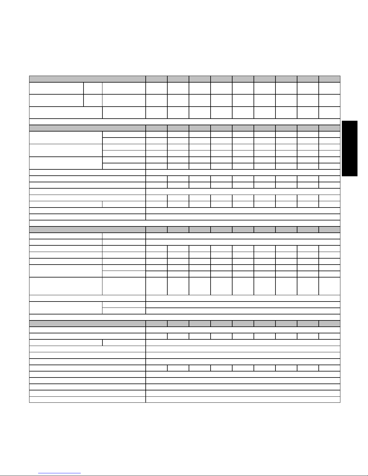
SPECIFICATIONS
The furnace should be sized to provide 100 percent of the design
heating load requirement plus any margin that occurs because of
furnace model size capacity increments. None of the furnace
model sizes can be used if the heating load is 20,000 BTU or
lower. Use Air Conditioning Contractors of America (Manual J
and S); American Society of Heating, Refrigerating, and
Air-Conditioning Engineers; or other approved engineering
Heating Capacity and Efficiency 30040 36040 36060 48060 48080 60080 48100 60100 60120
Input
Output
Certified Temperature
Rise Range ºF (ºC)
Airflow Capacity and Blower Data 30040 36040 36060 48060 48080 60080 48100 60100 60120
Rated External Static
Pressure (in. W.C.)
Airflow Delivery
@ Rated ESP (CFM)
Cooling Capacity (tons)
Direct-Drive Motor Type Permanent Split Capacitor (PSC)
Direct-Drive Motor HP 0.3 0.5 0.3 0.5 0.5 0.75 0.5 0.75 0.75
Motor Full Load Amps 4.6 6.8 4.6 7.9 7.4 7.9 6.5 11.1 11.1
RPM Range 500 - 1150
Speed Selections 4 5 4 4 5 5 4 4 4
Blower Wheel Dia x Width in. 11 x 7 11 x 8 11 x 7 11 x 8 11 x 8 11 x 10 11 x 10 11 x 10 11 x 11
Air Filtration System Field Supplied
Filter Used for Certified Watt Data* KGAWF**06UFR
High
Heat
High
Heat
(BTUH) 40,000 40,000 60,000 60,000 80,000 80,000 100,000 100,000 120,000
(BTUH) 37,000 37,000 56,000 56,000 75,000 75,000 93,000 93,000 112,000
High Heat
Heating 0.10 0.10 0.12 0.12 0.15 0.15 0.20 0.20 0.20
Cooling 0.5 0.5 0.5 0.5 0.5 0.5 0.5 0.5 0.5
High Heat 910 980 910 980 1030 1115 1480 1550 2070
Cooling 970 1140 1155 1505 1555 1885 1490 1970 2050
400 CFM/ton 2.5 2.5 2.5 3.5 4 4.5 3.5 5 5
350 CFM/ton 2.5 3 3 4 4.5 5.0 4.0 5.5 5.5
40 - 70
(22 - 39)
35 - 65
(19 - 36)
method to calculate heating load estimates and select the furnace.
Excessive oversizing of the furnace may cause the furnace and/or
vent to fail prematurely, customer discomfort and/or vent freezing.
Failure to follow these guidelines is considered faulty installation
and/or misapplication of the furnace; and resulting failure, damage,
or repairs may impact warranty coverage.
40 - 70
(22 - 39)
35 - 65
(19 - 36)
35 - 65
(19 - 36)
35 - 65
(19 - 36)
40 - 70
(22 - 39)
40 - 70
(22 - 39)
45 - 75
(25 - 42)
912SC
Electrical Data 30040 36040 36060 48060 48080 60080 48100 60100 60120
Input Voltage Volts-Hertz-Phase 115-60-1
Operating Voltage Range Min-Max 104-127
Maximum Input Amps Amps 5.2 7.4 5.3 8.6 8.1 8.6 7.3 11.9 11.9
Unit Ampacity Amps 7.5 10.3 7.6 11.7 11.1 11.7 10.1 15.8 15.8
Minimum Wire Size AWG 14 14 14 14 14 14 14 12 12
Maximum Wire Length
@ Minimum Wire Size
Maximum Fuse/Ckt Bkr
(Time-Delay Type Recommended)
Transformer Capacity (24vac output) 40 VA
External Control Power
Available
Controls 30040 36040 36060 48060 48080 60080 48100 60100 60120
Gas Connection Size 1/2" - NPT
Burners (Monoport) 2 2 3 3 4 4 5 5 6
Gas Valve (Redundant) Manufacturer White Rodgers
Minimum Inlet Gas pressure (in. W.C.) 4.5
Maximum Inlet Gas pressure (in. W.C.) 13.6
Ignition Device Silicon Nitride
Limit Control 195 180 220 190 185 195 220 220 165
Heating Blower Control (Heating Off-Delay) Adjustable: 90, 120, 150, 180 seconds
Cooling Blower Control (Time Delay Relay) 90 seconds
Communication System none
Thermostat Connections Com24V,R,W,G,Y
Accessory Connections EAC (115vac); HUM (24vac)
* See Accessory List for part numbers available.
Feet 49 36 48 31 33 31 36 36 36
(M) (14.9) (11.0) (14.6) (9.4) (10.1) (9.4) (11.0) (11.0) (11.0)
Amps 15 15 15 15 15 15 15 20 20
Heating 27.9 VA
Cooling 34.6 VA
3
91 - Legacy
92 - Preferred
98 - Evolution
912SC
1 - 2
Family/Tier
98
3
Base Eff.
6
0 - +90 AFUE
2 - +92 AFUE
3 - +93 AFUE
5 - +95 AFUE
6 - +96 AFUE
7 - +97 AFUE
4
Htg. Stages
T
S - Single Stage
T - Two Stage
M - Modulating
MODEL NUMBER NOMENCLATURE
Example of a Model Number
5
Major Series
A
Major Series
6 - 7
Clg. Cap.
30
24 - 800 CFM
30 - 1000 CFM
36 - 1200 CFM
42 - 1400 CFM
48 - 1600 CFM
54 - 1800 CFM
60 - 2000 CFM
66 - 2200 CFM
(@ 0.5” ESP)
Not all familes have these models.
8 - 10
Htg. Cap.
040
040= 40,000 BTU
060= 60,000 BTU
080= 80,000 BTU
100=100,000 BTU
120=120,000 BTU
140=140,000 BTU
11
Motor
V
S - Standard
E - Energy Efficient
V - Variable Speed
14 - 14.2”
17 - 17.5”
21 - 21.0”
24 - 24.5”
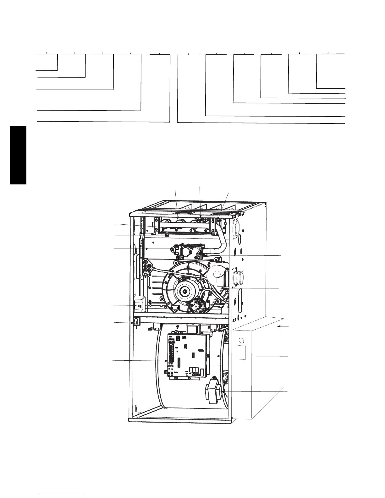
FURNACE COMPONENTS
HOT SURFACE
GAS BURNER
IGNITER
MANUAL RESET
ROLLOUT SWITCH
12 - 13
Width
14
Voltage
Voltage
14
A
15
Features
--
L - Low NOx
16
Minor Series
A
A12374
FLAME
SENSOR
MANUAL RESET
ROLLOUT SWITCH
GAS VALVE
OPERATING INSTRUCTIONS
NOT SHOWN (LOCATED ON
MAIN FURNACE DOOR, SEE
OPERATING INSTRUCTIONS
INSIDE DOOR FIGURE).
ELECTRICAL JUNCTION
BOX (IF REQUIRED,
LOCATION MAY VARY)
BLOWER DOOR
SAFETY SWITCH
FURNACE
CONTROL
BOARD
MAIN LIMIT SWITCH
(BEHIND GAS VALVE)
INDUCER MOTOR
ASSEMBLY
MEDIA CABINET
BLOWER AND
MOTOR
CAPACITOR/
POWER CHOKE
(IF USED)
RATING PLATE NOT SHOWN
(LOCATED ON BLOWER DOOR)
REPRESENTATIVE DRAWING ONLY, SOME MODELS MAY VARY IN APPEARANCE.
A11408
4
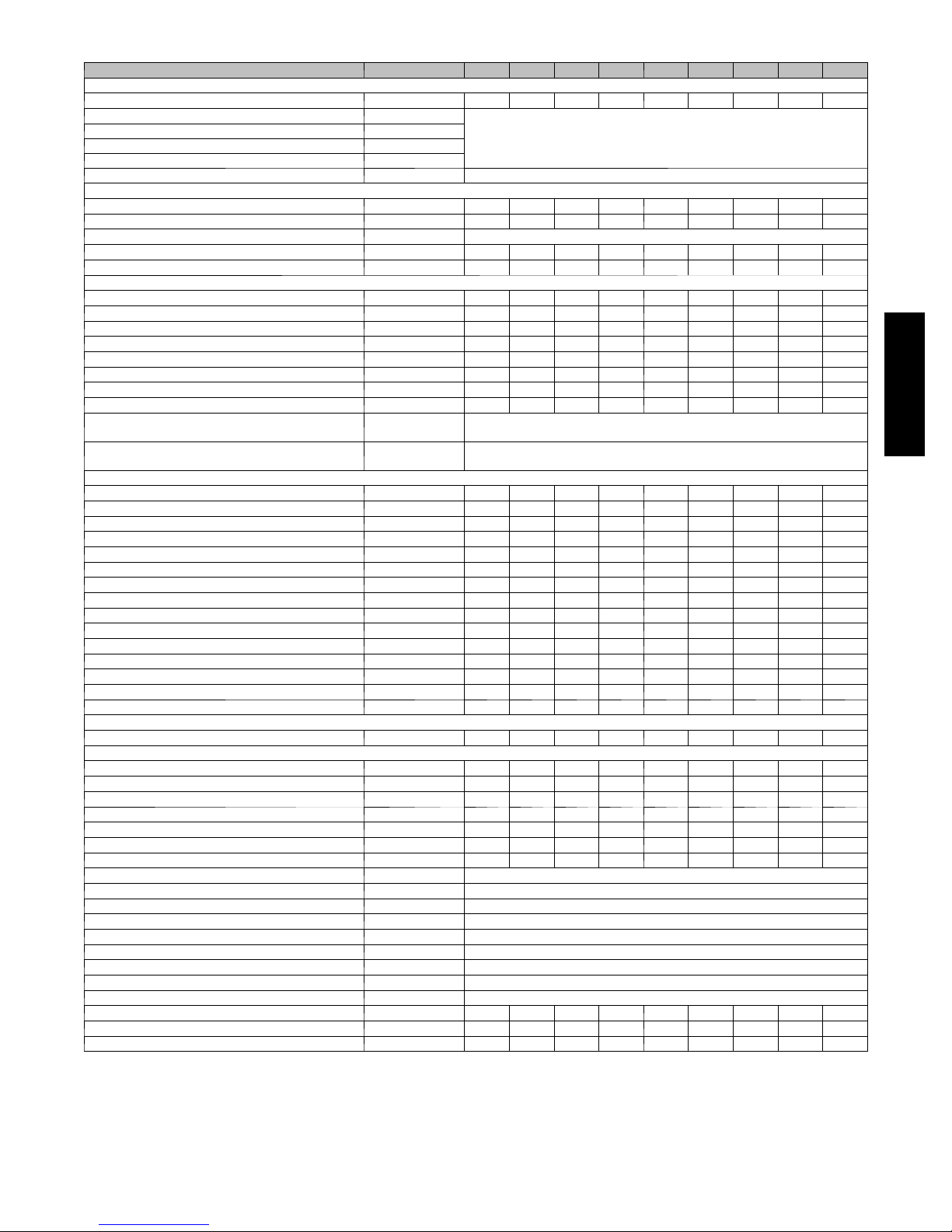
ACCESSORIES
Venting Accessories
Vent Kit - Through the Cabinet KGADC0101BVC D D D D D D D D D
Vent Terminal - Concentric - 2” (51 mm) KGAVT0701CVT
Vent Terminal - Concentric - 3” (76 mm) KGAVT0801CVT
Vent Terminal Bracket - 2” (51 mm) KGAVT0101BRA
Vent Terminal Bracket - 3” (76 mm) KGAVT0201BRA
Vent Kit --- Rubber Coupling KGAAC0101RVC See Venting Tables
Condensate Drainage Accessories
Freeze Protect Kit - Trap Heater KGAHT0201CFP D D D D D D D D D
CPVC to PVC Drain Adapters - 1/2” CPVC to 3/4” PVC KGAAD0110PVC D D D D D D D D D
Horizontal Trap Grommet - Direct Vent KGACK0101HCK All DV Horizontal
Condensate Neutralizer Kit P908---0001 D D D D D D D D D
External Trap Kit KGAET0201ETK D D D D D D D D D
Ductwork Adapter Accessories
Furnace Base Kit for Combustible Floors KGASB0201ALL D D D D D D D D D
Coil Adapter Kits --- No Offset KGADA0101ALL D D D D D D D D D
Coil Adapter Kits --- Sin gle Offset KGADA0201ALL D D D D D D D D D
Coil Adapter Kits --- Double Offset KGADA0301ALL D D D D D D D D D
Return Air Base (Upflow Applications) 14.0 - --in . wide KGARP0301B14 D D
Return Air Base (Upflow Applications) 17.5 - --in . wide KGARP0301B17 D D D
Return Air Base (Upflow Applications) 21.0 - --in . wide KGARP0301B21 D D D
Return Air Base (Upflow Applications) 24.5 - --in . wide KGARP0301B24 D
IAQ Device Duct Adapters 20.0 ---in . IAQ to 16 in. Side
Return
IAQ Device Duct Adapters 24.0 ---in . IAQ to 16 in. Side
Return
Gas Conversion Accessories
Mobile Home Kit KGBMH0601KIT D D D D D D D D D
Gas Conversion Kit - Nat to LP KGBNP50011SP D D D D D D D D D
Gas Conversion Kit - LP to Nat KGBPN42011SP D D D D D D D D D
GasOrificeKit-#42(NatGas) LH32DB207 D D D D D D D D D
GasOrificeKit-#43(NatGas) LH32DB202 D D D D D D D D D
GasOrificeKit-#44(NatGas) LH32DB200 D D D D D D D D D
GasOrificeKit-#45(NatGas) LH32DB205 D D D D D D D D D
GasOrificeKit-#46(NatGas) LH32DB208 D D D D D D D D D
GasOrificeKit-#47(NatGas) LH32DB078 D D D D D D D D D
GasOrificeKit-#48(NatGas) LH32DB076 D D D D D D D D D
Gas Orifice Kit - #54 (LP) LH32DB203 D D D D D D D D D
Gas Orifice Kit - #55 (LP) LH32DB201 D D D D D D D D D
Gas Orifice Kit - #56 (LP) LH32DB206 D D D D D D D D D
Gas Orifice Kit - 1.25mm (L P) LH32DB209 D D D D D D D D D
Gas Orifice Kit - 1.30mm (L P) LH32DB210 D D D D D D D D D
Control Accessories
Twinning Kit KGATW0701HSI D D D D D D D
IAQ Accessories
Filter Rack --- Side Return for 1” Filters KGAFR0201ALL D D D D D D D D D
Filter Rack --- Bottom Return for 1” Filters --- 14.2” wide KGBFR0401B14 D D D
Filter Rack --- Bottom Return for 1” Filters --- 17.5” wide KGBFR0501B17 D D
Filter Rack --- Bottom Return for 1” Filters --- 21.0” wide KGBFR0601B21 D D D
Filter Rack --- Bottom Return for 1” Filters --- 24.5” wide KGBFR0701B24 D
Filter Pack (6 pack) --- Washable - 16x25x1 KGAWF1306UFR D D D D D D D D D
Filter Pack (6 pack) --- Washable - 24x25x1 KGAWF1506UFR D D D D D D D D D
EZ-Flex Filter - 16” (406 mm) EXPXXFIL0016 Use with EZXCAB --- 1016
EZ-Flex Filter - 20” (508 mm) EXPXXFIL0020 Use with EZXCAB --- 1020
EZ-Flex Filter - 24” (610 mm) EXPXXFIL0024 Use with EZXCAB---1024
EZ-Flex Filter with End Caps - 16” (406 mm) EXPXXUNV0016 Use with E ZXCAB --- 1016
EZ-Flex Filter with End Caps - 20” (508 mm) EXPXXUNV0020 Use with E ZXCAB --- 1020
EZ-Flex Filter with End Caps - 24” (610 mm) EXPXXUNV0024 Use with E ZXCAB --- 1024
Cartridge Media Filter - 16” (406 mm) FILXXCAR0016 Use with FILCABXL ---1016
Cartridge Media Filter - 20” (508 mm) FILXXCAR0020 Use with FILCABXL ---1020
Cartridge Media Filter - 24” (610 mm) FILXXCAR0024 Use with FILCABXL ---1024
EZ Flex Cabinet Side or Bottom Return 4” Filters --- 16” EZXCABCC0016 D D D D D
EZ Flex Cabinet Side or Bottom Return 4” Filters --- 20” EZXCABCC0020 D D D
EZ Flex Cabinet Side or Bottom Return 4” Filters --- 24” FILCABXL0024 D
D = Used with the model furnace
DESCRIPTION PA R T N UMB E R 30040 36060 36040 48060 48080 60080 48100 60100 60120
See Venting Tables
KGAAD0101MEC 20”x25” IAQ Devices
KGAAD0201MEC 24”x25” IAQ Devices
912SC
5
 Loading...