

Page 1
Installation, Start-up
and Service Instruction
ELECTRONIC AIR CLEANER
NOTE: Read the entire instruction manual before starting the
installation.
SAFETY CONSIDERATIONS
Improper installation, adjustment, alteration, service, maintenance,
or use can cause explosion, fire, electrical shock, or other
conditions which may cause personal injury or property damage.
Consult a qualified installer, service agency, or your distributor or
branch for information or assistance. The qualified installer or
agency must use factory authorized kits or accessories when
modifying this product. Refer to the individual instructions packaged with the kits or accessories when installing.
Follow all safety codes. Wear safety glasses and work gloves.
Read these instructions thoroughly and follow all warning or
cautions attached to the unit. Consult local building codes and
National Electric Code (NEC) for special requirements.
Recognize safety information. This is the safety-alert symbol
When you see this symbol on unit or in instructions and manuals,
be alert to potential for personal injury.
Understand the signal word DANGER, WARNING, or CAUTION. These words are used with the safety-alert symbol. DANGER identifies the most serious hazards which willresultinsevere
personal injury or death. WARNING signifies a hazard which
could result in personal injury or death. CAUTION is used to
identify unsafe practices which would result in minor personal
injury or product and property damage. NOTE is used to highlight
suggestions that will result in enhanced installation, reliability, or
operation.
INTRODUCTION
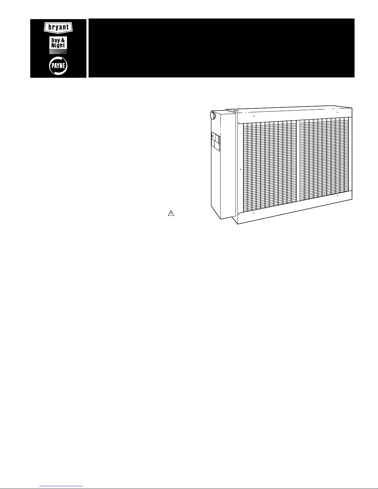
Model 9011KAX Electronic Air Cleaner (EAC) is available in 3
sizes: 012 (300 to 1400 CFM), 016 (500 to 1800 CFM), and 020
(700 to 2000 CFM). (See Fig. 1.)
These plate-type air cleaners are designed for use with residential
and light commercial forced-air heating and/or cooling systems.
They may be installed in the vertical or horizontal section of a
typical return-air duct system. (See Fig. 2.)
These air cleaners are easily field-converted from right- to lefthand units. Cabinets are designed to support up to 400 pounds
when used in under-the-furnace applications.
A. Cabinet
The cabinet includes an electrical junction box and power safety
interlock, and houses the air cleaner components. These components are:
1. Mechanical pre-filters—Expanded aluminum mesh firststage filter that removes lint and large dust particles.
2. Cell assemblies—Cells consisting of combined ionizer
wires and collector plates.
Ionizer part of cell has tungsten wires that receive positive
charge and are mounted between grounded aluminum
channels supported by glazed ceramic insulators.
Collector part of cell consists of alternately charged collector plates.
901KAX
Cancels: II 901K-12-3 II 901K-12-4
10-01-94
.
A91465
Fig. 1—Model 31KAX
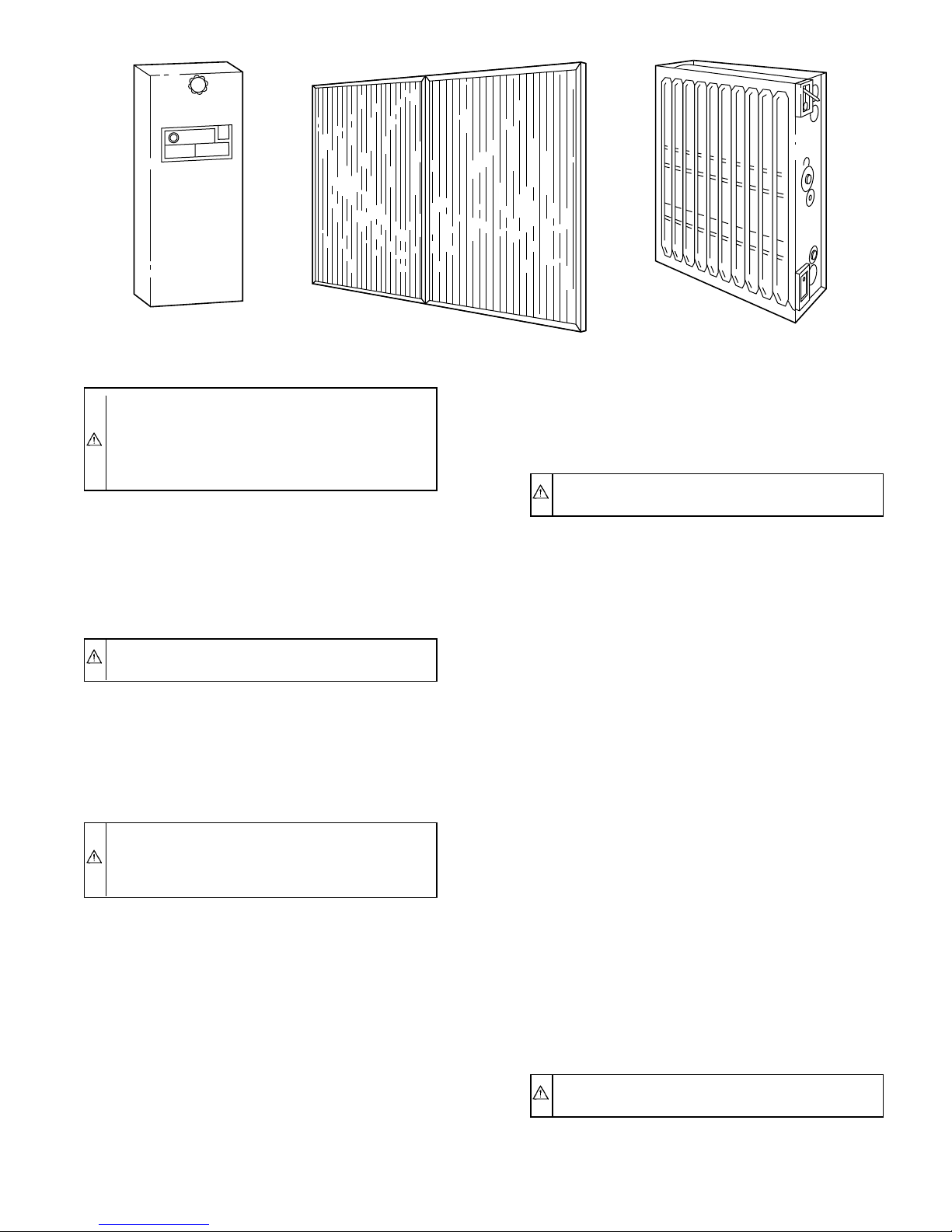
The EAC components are listed below and shown in Fig. 3.
1. Power door assembly.
2. Two pre-filters.
3. Cabinet containing 2 air-cleaning cell assemblies.
4. A parts bag including electrical bushing, plug buttons, wire
chase, and airflow label.
B. Power Door Assembly
The power door assembly consists of:
1. Unit operation light, ON-OFF switch, and door attachment
knob—all installed on door cover.
2. Door base plate contains a solid-state power pack that
converts 120vac to high voltage DC (a 240v Conversion
Kit, KEAVC0101240 is available). All wiring is mounted
internally. A line-voltage disconnect (male plug) and highvoltage buss bar are mounted on the base plate externally.
Four screws must be removed toexposethepower pack and
wiring.
The supply circuit to the power pack, which is wired across the
furnace blower motor, is controlled by an ON-OFF power switch.
With the power switch ON (assuming power door is in place and
blower motor is operating), 120vac ± 10 percent single-phase, 60
Hz power is applied to the power pack (240v conversion kit
transformer converts 240v to 120vac). Output of the power pack
assembly is approximately 7300vdc.
These Installation Instructions consist of the following:
Section I—Locating Unit
Section II—Installation
Section III-Electrical Connections
Section IV-Startup and Adjustments
Section V—Routine Maintenance and Service
—1—
Page 2
7
⁄8-IN. ELECTRICAL
ENTRANCE FOR DUCT
APPLICATION
8 1⁄2″
REAR MOUNTING FLANGE
A
1
⁄16″
2
16 7⁄8″
1″
C
B
ELECTRICAL ENTRANCE (5⁄8-IN. DIA)
FOR FURNACE APPLICATIONS
3″
21″
OPERATION
LIGHT
LOGO
REMOVABLE
POWER DOOR
KNOB
ON/OFF
SWITCH
A91466
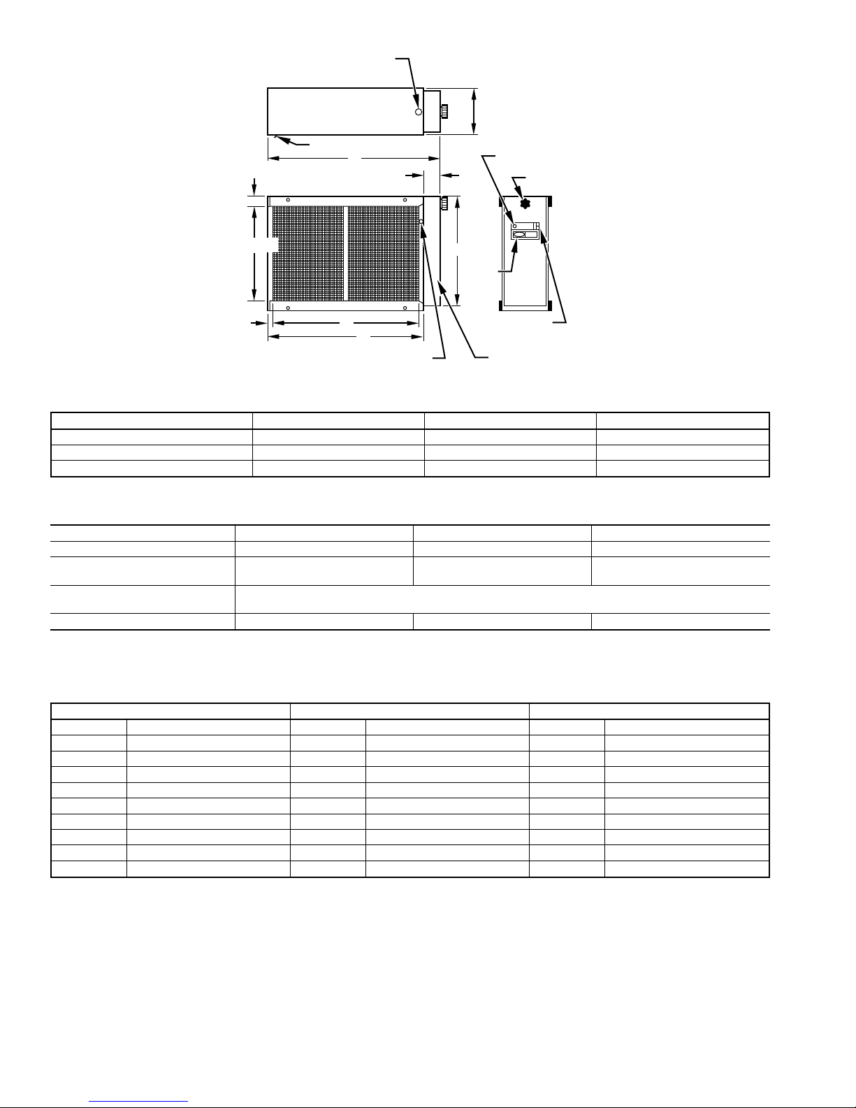
MODEL A B C
901KAX012 24-3/4 21-3/4 19-1/2
901KAX016 27-1/4 24-1/4 22
901KAX020 31-1/2 28-1/2 26-1/4
Fig. 2—Dimensional Drawing
TABLE 1—COMPONENT INFORMATION
MODEL 901KAX012 901KAX016 901KAX020
Air Volume Range 300-1400 500-1800 700-2000
Electrical Data
(Input to power door)
Electrical Data
(Output To Collector Cell)
Approx Ship. Wt. 120v 50 54 57
Note: Using the EAC on air duct systems designed for airflows lower than 300 CFM for 012-size units, 500 CFM for 016-size units, or 700 CFM for 020-size units, is
not recommended.
120v, single phase, 60 Hz 120v, single phase, 60 Hz 120v, single phase, 60 Hz
120v—1.0 milliamps @ 7300vdc
TABLE 2—PRESSURE DROP AT VARIOUS AIRFLOWS
901KAX012 901KAX016 901KAX020
CFM Pressure Drop (In. wc) CFM Pressure Drop (In. wc) CFM Pressure Drop (In. wc)
300 0.005 500 0.010 700 0.010
400 0.010 600 0.025 800 0.013
600 0.020 800 0.020 1000 0.018
800 0.030 1000 0.028 1200 0.023
1000 0.050 1200 0.035 1400 0.030
1100 0.060 1400 0.045 1600 0.038
1200 0.065 1600 0.065 1800 0.045
1300 0.075 1700 0.070 1900 0.048
1400 0.085 1800 0.080 2000 0.050
See Service Guide, and Troubleshooting Flow Chart for supplementary information.
I. LOCATING UNIT
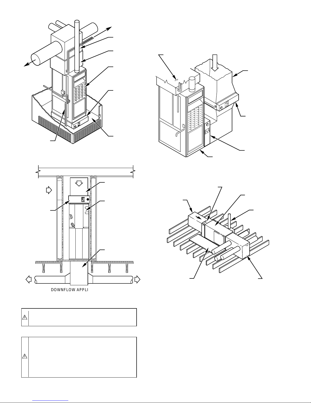
Fig. 4 shows the air cleaner in the return-air duct of various furnace
installations, with or without air conditioning. Other methods of
installing the unit are permissible if the design criteria outlined in
this section is observed.
A. A. Planning an Installation
When planning an installation, consider the following:
1. Air cleaner is approved only for indoor installation. If
outdoor installation is used, unit must be housed in weatherproof enclosure.
2. Air cleaner may be placed in horizontal position on its right
or left side or in vertical position on its bottom or back. It
must be installed on inlet air side of heating and/or cooling
unit. Be sure that airflow through air cleaner is in same
direction as "airflow arrows" on cells.
—2—
Page 3
POWER DOOR
ASSEMBLY
PRE-FILTERS CELL ASSEMBLY
Fig. 3—View of Major Components
CAUTION: Cabinets will support a maximum weight of
400 lbs when installed beneath a vertical furnace or
air-handling unit. When setting furnace on cabinet, do not
drop it into place. Position furnace correctly on cabinet to
prevent a corner from slipping down and damaging
cabinet.
3. Allow minimum 16-in. clearance in front of unit for
cleaning and maintenance.
4. Air outlets and returns must not be blocked with furniture,
drapes, or other objects.
5. Air cleaner should be installed where all air circulated by
system will pass through it.
CAUTION: Never use air cleaner to collect grease or
other flammable contaminants.
B. Humidifiers
An evaporative, supply-duct-mounted humidifier may be installed
without affecting the EAC. A bypass-type evaporative humidifier
should be installed so that the moist air does not contact the air
cleaner. When an atomizing-type humidifier is used, it should
always be installed in the supply-air system.
CAUTION: If an atomizing-type humidifier is installed
upstream from the air cleaner, the efficiency of the
electronic cells will be decreased by high humidity, salts,
and minerals. Service problems will result.
If bypass-type humidifier is installed upstream from the EAC, the
following precautions should be taken.
1. Humidifier must be installed as far from EAC as possible.
2. A standard, disposable furnace filter must be installed
between humidifier and EAC to trap water droplets and
mineral salts.
3. Electronic cells of air cleaner must be washed frequently to
prevent mineral deposit buildup.
C. Outdoor Air
When outdoor air is added to the return-air duct, sufficient heat
must be added to maintain the return-air temperature of 40°F
minimum or minimum specified by air handling equipment manufacturer. Temperatures lower than 40°F can cause ionizer wire
failure under certain conditions.
A91467
NOTE: The maximum operating temperature of the EAC is
125°F.
II. INSTALLATION
NOTE: See Fig. 4 for suggested installation positions.
CAUTION: Turn off all power to furnace or fan coil
before beginning installation.
Proceed as follows to install EAC:
1. Remove and discard existing furnace mechanical filters.
They are not required when using an EAC. Thoroughly
clean blower compartment of furnace.
2. Move ON-OFF switch to OFF and remove power door by
rotating knob (approximately 10 turns counterclockwise)
until door is free. Grasp power door by knob and remove it
from cleaner cabinet by pulling it towards you. This motion
disengages power supply connector.
3. Slide out pre-filters and air cleaner cells.
4. For size 016 EAC furnace side application, cut open return
knockout at the side of the furnace cabinet. For size 012 and
020, cut opening as shown in Fig. 5—Opening Detail.
5. In order to prevent air leakage, use foam tape provided to
attach air cleaner to side of furnace or system blower.
NOTE: The unit is shipped for furnace right side application. For
left side application, rotate rear mounting flange 180° by removing
4 screws in the back of the air cleaner. Be sure all 4 screws are in
place after the rotation. Relocate the junction box on the furnace to
the right side, if required.
6. Hook back flange into the opening. Use air cleaner cabinet
front support flange adjacent to the unit as template and drill
2 holes on furnace casing. (See Fig. 6.)
7. Secure the unit by screwing 2 provided screws into drilled
holes. (See Fig. 6.)
8. Prepare return-air duct for installation to unit. Return air
must use full cabinet opening. Duct should run straight into
unit.
CAUTION: Do not baffle any portion of the entering-air
side of the air cleaner.
NOTE: Baffles may be necessary in upflow applications.
(See Fig. 7.)
—3—
Page 4
DOWNFLOW APPLICATION
RETURN AIR
PLENUM
FAN-COIL
UNIT
SUPPLY AIR
PLENUM
ELECTRONIC
AIR CLEANER
A91468
SUPPLY AIR
PLENUM
COOLING
COIL
UPFLOW
FURNACE
ELECTRONIC
AIR CLEANER
RETURN AIR
PLATFORM
GAS SUPPLY
UPFLOW APPLICATION
A91470
VENT
RETURN
AIR PLENUM
ELECTRONIC
AIR CLEANER
HORIZONTAL
FURNACE
SERVICE
PLATFORM
SUPPLY
AIR PLENUM
HORIZONTAL FURNACE APPLICATION
A91469
UPFLOW
FURNACE
3 TO 1
TRANSITION
DUCT WORK
ALTERNATE
AIR CLEANER
POSITION
AIRFLOW
ELECTRONIC
AIR CLEANER
COOLING
COIL
FURNACE SIDE APPLICATION
—4—
CAUTION: If flanged sheet metal ducts are metalscrewed to the unit casing, do not use screws longer than
1/2 in.
CAUTION: Airflow across air cleaner must be uniform
for best results. Install turning vanes if air cleaner is
installed close to an elbow. Depending on size of furnace,
it may or may not be necessary to reduce ductwork on
leaving-air side of air cleaner. For any application,
maintain a 3-to-1 duct reduction ratio (3 in. of duct length
for every 1-in. of reduction in size).
A86134
Fig. 4—Typical Applications
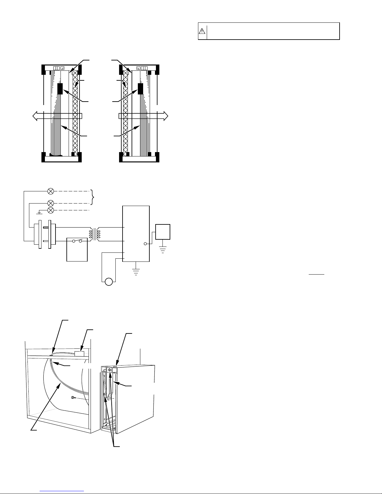
9. Check airflow and component configuration. (See Fig. 8.)
10. Seal all joints on downstream side of air cleaner to prevent
infiltration of contaminated air.
III. ELECTRICAL CONNECTIONS
All wiring must comply with applicable local and national codes.
To determine best power wiring routing refer to Section A for
Internal Electrical Connections and Section B for External Electrical Connections.
NOTE: For general information a line to line wiring diagram is
provided. (See Fig. 9.)
Page 5

FURNACE
KNOCKOUTS
1
⁄8 IN.
18 5⁄8″
17 1⁄4″
1
16
⁄4″
1
⁄4″
3
3
⁄4″
2
7
⁄16″
2
0
3
⁄4″
1
0
4 1⁄4″ 5 3⁄4″
5
DIA HOLE
REAR OF
25″
FURNACE
1
28
⁄2″
1
⁄8 IN.
DIA HOLE
1
⁄16″
18 5⁄8″
17 1⁄4″
1
16
⁄4″
3 1⁄4″
3
⁄4″
2
7
⁄16″
2
0
3
⁄4″
1
KNOCKOUTS
0
4 1⁄4″ 5 3⁄4″
1
5
⁄16″
FURNACE
1
⁄8 IN.
DIA HOLE
016012
1
⁄8 IN.
DIA HOLE
27 1⁄2″
28 1⁄2″
17
16 1⁄4″
REAR OF
FURNACE
7
2
⁄16″
1 3⁄4″
18 5⁄8″
1
15
10
3
2
FURNACE
KNOCKOUTS
1
⁄8 IN.
DIA HOLE
⁄4″
5
⁄8″
1
⁄2″
⁄4″
0
0
13
⁄16″
1 5⁄16″
3
⁄4 IN.
DIA HOLE
1
⁄8 IN.
DIA HOLE
020
27
1
⁄2″
28 1⁄2″
REAR OF
FURNACE
A91471
Fig. 5—Opening Detail
CAUTION: Be sure all incoming power is off before
beginning any procedures.
A. Internal Electrical Connections
Proceed as follows to make internal electrical connections.
1. With power door removed, remove junction box cover
adjacent to female plug on casing upper channel. (See Fig.
10.)
PLUG
BUSHINGS
SCREWS
FURNACE
OPENING
SCREWS
SCREWS
FLANGE
Fig. 6—Electronic Air Cleaner Installation
A89117
2. Install protective bushing from inside the air cleaner into the
upper hole on the side channel adjacent to the furnace. Be
sure bushing projects into furnace opening protecting wires
from sharp edges on cabinet opening.
3. Install protective bushing through top rail as shown in Fig.
10.
4. Plug unused hole on top of unit with plug provided in parts
bag.
5. Route power wires through bushing channel at top of
cabinet, down side channel, and through bushing in side
channel and into furnace opening. (See Fig. 10.)
6. Replace cover of junction box.
7. Install wire cover (provided in parts bag) under top flange
and secure to side channel with provided screw.
8. Connect power leads as follows:
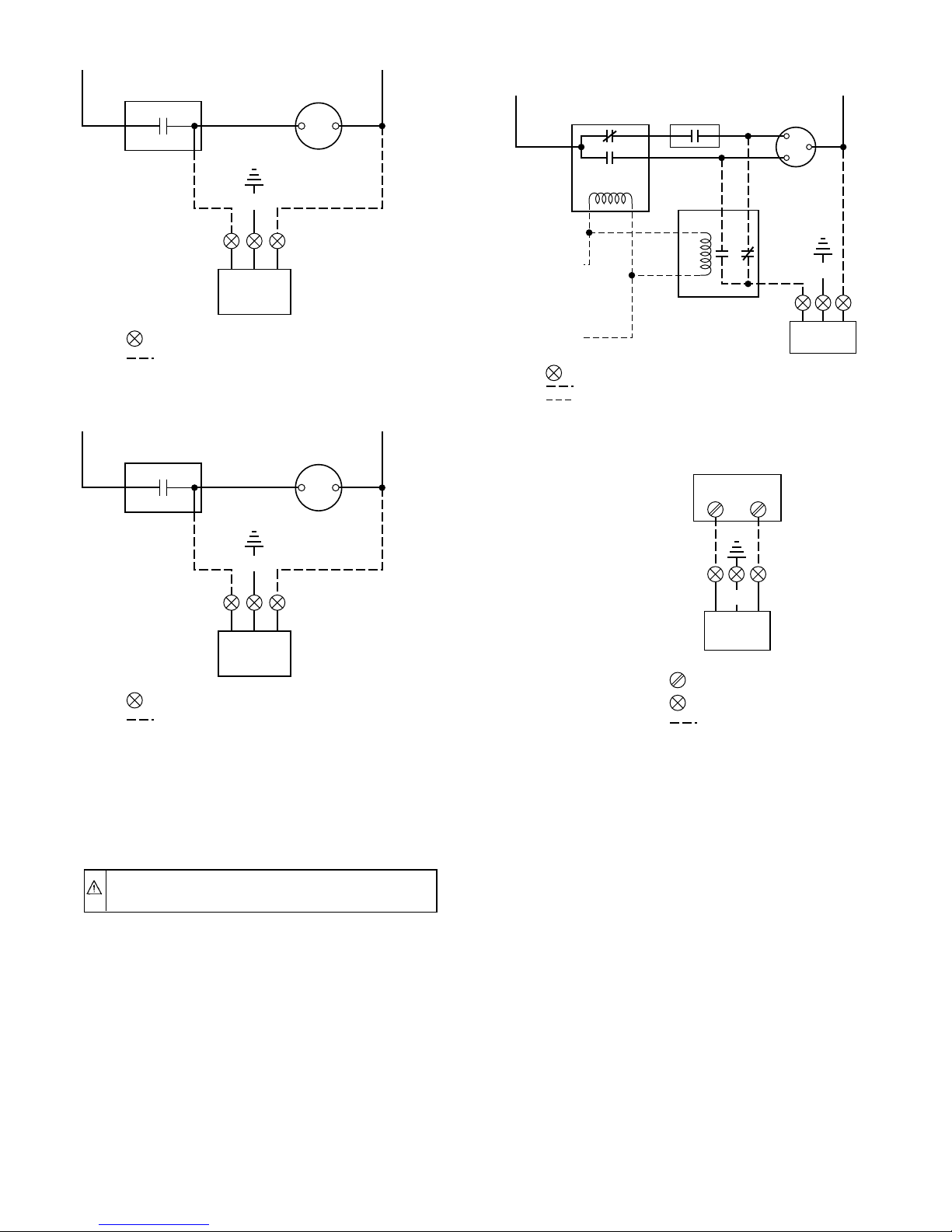
a. Single Speed Furnaces—EAC is wired in parallel with
fan motor. (See Fig. 11.)
b. Multispeed Direct-Drive Motor—If the EAC is wired
to a multispeed direct-drive motor, it must be isolated by
a relay or sail switch. Use either air cleaner relay P/N
P283-1203 or sail switch P/N 69105D1. (See Fig. 12 or
13.)
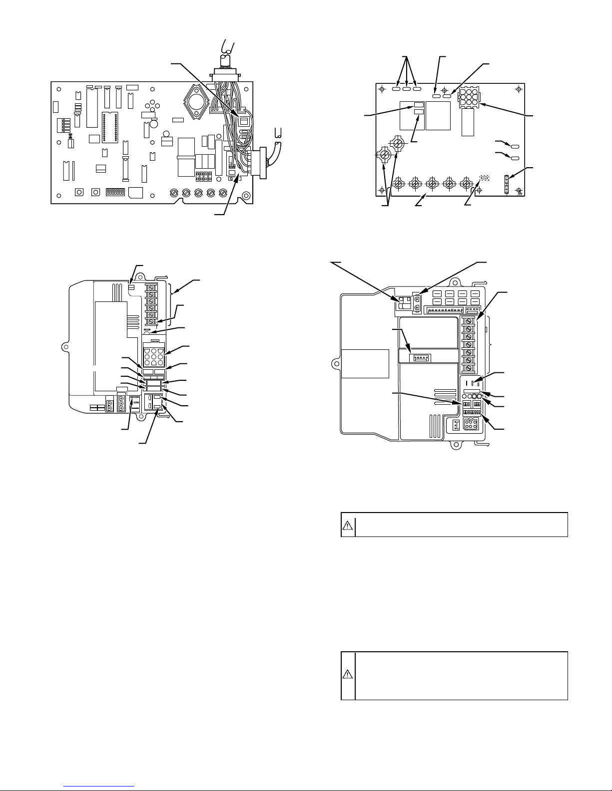
c. Furnaces with Printed-Circuit Boards—EAC is wired
to furnace terminals EAC 1 and EAC 2. See Fig. 14 for
wiring connections.
9. Connect ground wire to base unit ground.
FURNACE
BAFFLES
ELECTRONIC
AIR CLEANER
A91472
Fig. 7—Installing Baffles if Needed
—5—
Page 6
NOTE: For non-corporate furnaces, wire unit using conduit and
strain relief the wires.
IONIZER
WIRES
PREFILTERS
PROPER
AIRFLOW AIRFLOW
CONTACT
SPRING
LOCATION
CHARGED
COLLECTOR
PLATES
A91473
Fig. 8—Reversing Components for Opposite Airflow
BLK
WHITE
GREEN FIELD WIRED
INTERLOCK
(DO NOT
BYPASS)
WIRE CONN.
TRANSFORMER
*
WHITE
BLK
POWER
SWITCH
FIELD WIRING
GROUND
ASSY. FOR
FIELD CONN.
ON 208/240 UNITS ONLY
*
POWER
SUPPLY
WHT
WHT
LINE
VOLTAGE
BLK
BLK
HIGH
VOLTAGE
BLU
BLU
LED
BLU
BLU
Y
OPERATION LIGHT
UNIT
A89073
Fig. 9—Line-to-Line Wiring Diagram
BUSHING HOLES
FURNACE
INTERNAL
POWER WIRE
ROUTING
FURNACE
CONTROL
BOARD
GROUND
TOP PLUG
WIRE COVER FOR
CHANNEL
BUSHING HOLES
A94155
Fig. 10—Wire Routing
CAUTION: Be sure all internal wiring connections are
tight before power is returned to the unit.
B. External Electrical Connections
1. Attach power supply conduit to hole in top of EAC. Do not
use extension cord to connect to electrical power source.
2. Cut EAC wires to 6 in. in length. Strip the ends. Using
field-supplied wire nuts, connect power leads to black and
white pigtails extending from female receptacle. (See Fig.
10.)
NOTE: Do not connect aluminum conductor to electrical connections of the EAC. Use copper wire only.
3. Connect power leads as follows:
a. Single-Speed Furnaces. EAC is wired in parallel with
fan motor. (See Fig. 11.)
b. Multispeed Direct-Drive Furnaces. If the EAC is
wired to a multispeed direct-drive motor, it must be
isolated by a relay or sail switch. Use either air cleaner
relay P/N P283-1203 or sail switch P/N 69105D1. (See
Fig. 12 or 13.)
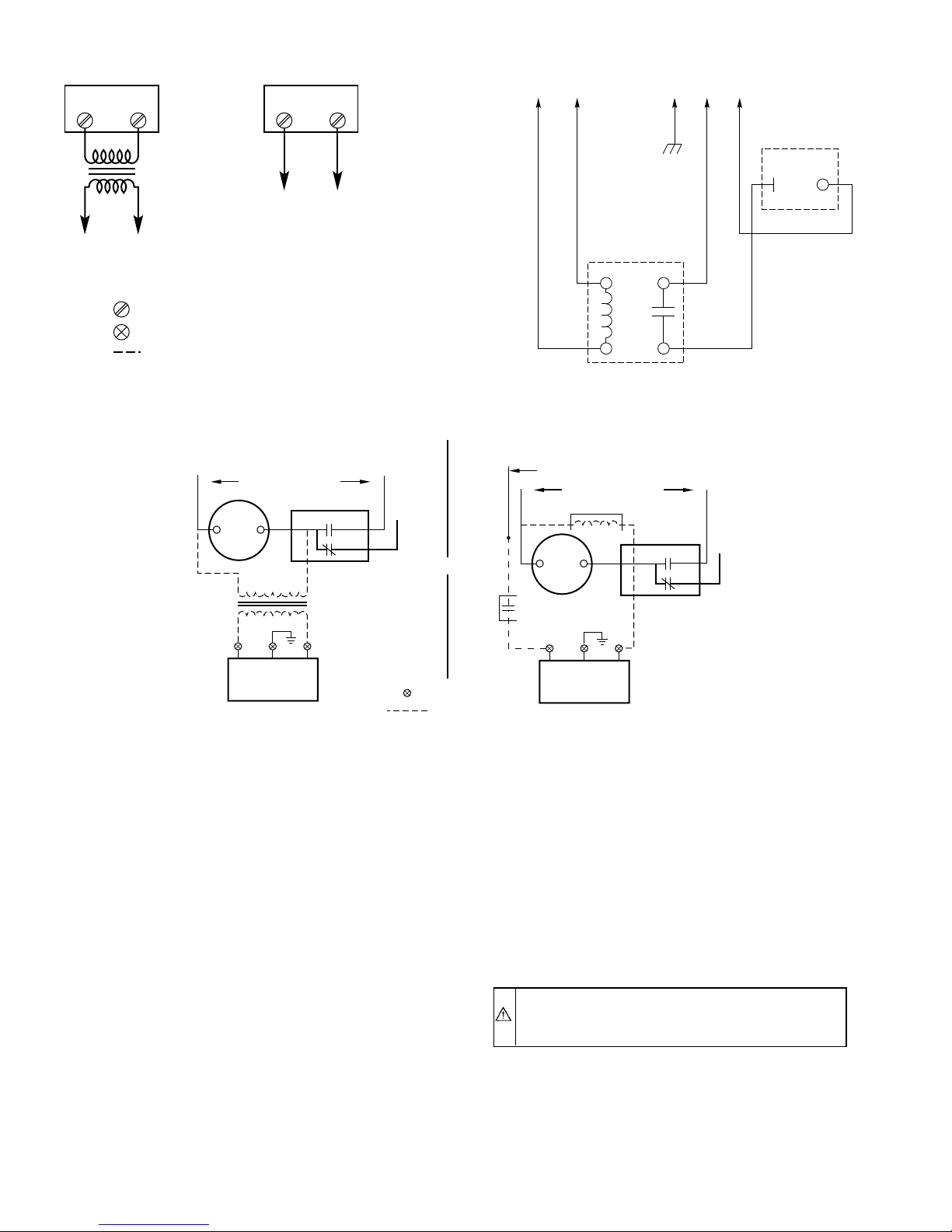
c. Fan Coils. EAC (120v) MUST be wired to fan coil
circuit board terminals EAC 1 and EAC 2, if applicable,
ONLY as shown in Fig. 15. Terminals EAC 1 and EAC
2 will supply 240vac. Terminal EAC 1 is energized
continuously; terminal EAC 2 is energized only with the
fan motor.
4. Connect EAC ground wire (green) to appropriate supply
ground.
5. Replace cover of junction box.
C. Fan Coils with Control Boards
1. Fan coil control boards with EAC hook-up terminals MUST
be wired using EAC1 and EAC2 connections when applicable. (See Figure 15.) Both EAC1 and EAC2 terminals
will supply 240vac. A 240v conversion kit MUST be used
to step down voltage to 120vac for proper electronic air
cleaner operation.
2. Fan coil control boards without EAC hook-up terminals
should be wired using a 240v conversion kit. Connect the
primary leads of transformer (240v) in parallel with fan
motor. (See Figure 16.) The secondary leads of transformer
(120v) connect to electronic air cleaner for proper operation. A field supplied accessory relay (240v) may also be
used in place of the 240v conversion kit. (See Figure 16.)
Apply 240v relay coil in parallel with fan motor. Connect
white (common) wire from EAC to N.O. contacts, then to
neutral at service panel. Check for 120v/60hz/1ph and
ensure separate ground is connected.
3. For fan coil control boards with AUX1 and AUX2 24vdc
terminals, use Kit No. KFAIR0101ACR which is offered
for use when 24v conversion kits may not be available. The
kit contains a 24vdc relay which mounts directly inside the
EAC cabinet. User supplied 110vac is activated by this
relay to power the air cleaner when G or W are present. This
preferred connection allows low-voltage wiring to be run
between the fan coil and the air cleaner and eliminates the
problems of controlling a 110vac air cleaner from the 230v
power supplied by the fan coil. (See Fig. 15.)
The ICM2 blower motor used in the FK4B Fan Coil is controlled
by low-voltage signals. The familiar 230vac air cleaner
control/power signal, EAC 1 and EAC 2, is not available. These
signals are replaced by a 24vdc signal which is provided at circuit
board terminals AUX 1 and AUX 2. This 24vdc signal is present
when either G or W is present and is active in all heating and
cooling modes.
—6—
Page 7
POWER SUPPLY (120V-60HZ-10)
BLK WHT
FAN SWITCH
GRD
GRN
BLK WHT OR YEL
WIRENUT, FACTORY SUPPLIED
120-V FIELD WIRING
FAN MOTOR
ELECTRONIC
AIR CLEANER
Fig. 11—Single-Speed Furnaces
POWER SUPPLY (120V-60HZ-10)
BLK WHT
FAN SWITCH
GRD
FAN MOTOR
A91474
BLK
TO "G" ON
THERMOSTAT
TO "C" ON
THERMOSTAT
WIRENUT, FACTORY SUPPLIED
POWER SUPPLY (120V-60HZ-10)
FAN RELAY FAN SWITCH FAN MOTOR
LO
C
HI
AIR CLEANER
RELAY (FIELD
SUPPLIED)
120-V FIELD WIRING
24-V FIELD WIRING
BLK
ELECTRONIC
AIR CLEANER
WHT
OR
RED
GRD
GRN
YEL
OR
WHT
A91475
Fig. 12—Multispeed Direct-Drive Furnaces with Field-
Supplied Air Cleaner Relay
EAC1 EAC2
GRD
FURNACE
TERMINAL
BOARD
GRN
BLK WHT OR YEL
ELECTRONIC
AIR CLEANER
WIRENUT, FACTORY SUPPLIED
120-V FIELD WIRING
A91474
Fig. 13—Multispeed Direct-Drive Furnaces with Field-
Supplied Sail Switch
In heat pump applications, the G signal is present in both cooling
and heating modes, permitting the EAC to be controlled from the
G signal only. A user supplied 24vac relay can be driven by the G
terminal, eliminating the need for the relay kit. The selection and
mounting of this ac relay is the responsibility of the installer.
CAUTION: Be sure all field electrical connections are
tight before power is restored to the unit.
D. Final Assembly
1. Slide pre-filters and air cleaner cells into cabinet.
NOTE: Units are shipped for air entering the right-hand side of
the air cleaner. Reverse the position of the pre-filter and the air
cleaner cells in the cabinet for air entering the left-hand side of the
air cleaner as indicated in Fig. 8. Be sure all airflow arrows are
pointing in the direction of the airflow through the air cleaner and
that the pre-filter is on the entering-air side.
2. Check contact spring location. Cell contact springs MUST
be relocated for left-hand units or applications. Remove
screw holding contact spring to cells and reinstall at
opposite end. (See Fig. 24.) Be sure all airflow arrows are
pointing in the direction of the airflow through the air
cleaner and that the pre-filters are on the entering-air side.
GRNBLK YEL OR WHT
ELECTRONIC
AIR CLEANER
SCREW TERMINAL
WIRENUT, FACTORY SUPPLIED
120-V FIELD WIRING
A91477
Fig. 14—Furnaces with Printed-Circuit Board
3. Deform pre-filter guide on side opposite pre-filters so
pre-filters can not be reinstalled incorrectly.
4. Replace power door by first inserting bottom tab into place
on bottom edge of door opening. Push top of door and guide
door attachment knob screw into threads. Turn knob clockwise until screw engages threads in casing. Continue
turning knob clockwise until door is secure. Ensure good
electrical contact between power door and unit components.
5. Unit can be installed with airflow through cabinet in either
direction. Apply provided airflow decal to cabinet, observing actual airflow direction. (See Fig. 24.)
IV. STARTUP AND ADJUSTMENTS
The electronic components of the unit convert the incoming vac to
vdc power supply. Unfiltered, contaminated air passes through an
aluminum mesh pre-filter which removes large airborne particles
and distributes the air uniformly across the ionizer-collector
assembly. The air passes through the ionizer and is charged with
7300vdc. The ionizer imparts a positive electrical charge to the
remaining contaminants. As the air continues through the collector
section, the charged contaminants are attracted to the alternately
charged collector plates. The charged contaminants are electrostatically held by the collector, purifying the airstream.
1. Ensure that entire EAC is clean, dry, and free of foreign
objects.
—7—
Page 8
EAC1 EAC2
TO 120-V
ELECTRONIC
AIR CLEANER
SCREW TERMINAL
WIRENUT, FACTORY SUPPLIED
OR
240:120-V
30 VA
TRANSFORMER
240-V CONVERSION
120-V FIELD WIRING
L
1
240V–60Hz–1PH
FAN
MOTOR
EAC1 EAC2
TO 240-V
ELECTRONIC AIR
CLEANER (WITH
KIT INSTALLED)
A91489
Fig. 15—Fan Coils with Printed-Circuit Boards
L
2
FAN RELAY
COM N.O.
N.C.
OR
240V
120V
KEAVC0101240
240/120V
40VA
TRANSFORMER
FK4B 110 VAC BRANCH CKT
AUX1 AUX2 GND HOT NEUT
BLK
GRN
WHT
24 VDC RELAY
NEUTRAL
L
1
240V–60Hz–1PH
ACCESSORY RELAY (240V)
FAN
MOTOR
N.O.
CONTACTS
GRD
FAN
RELAY
COM N.O.
N.C.
L
2
EAC
PLUG
A93217
YEL or
GRN BLK
WHT
ELECTRONIC
AIR CLEANER
120V
Fig. 16—Fan Coil with CESO130003 Control Board
2. Restore power to system.
3. Move ON-OFF switch on power door to ON position.
4. Set room thermostat to start blower.
5. Check to see if operation light is glowing. This indicates
proper power to the cells.
NOTE: Leave these Installation Instructions with the owner to
enable the owner to perform routine maintenance and service.
V. ROUTINE MAINTENANCE AND SERVICE
Your new EAC requires periodic maintenance for optimum
performance. You may perform this service or have your serviceman handle it for you.
Cleaning of the cell assembly and pre-filter is required 2 or 3 times
a year. Frequency will depend on size of home, number of
occupants, smoking habits, etc.
The odor of ozone may be noticeable during operation of an EAC.
A somewhat higher ozone generation rate during the first week or
2 of operation may be caused by sharp edges on some of the new
high-voltage parts. Normal use dulls these sharp edges in a short
time.
WIRENUT
120V FIELD
WIRING
YEL or
WHT
ELECTRONIC
AIR CLEANER
120V
BLK
A94320
The odor of ozone is detectable by an average person at levels as
low as 0.0030 to 0.010 parts per million (PPM). The concentration
of ozone produced in a home by an EAC ranges from 0.006 to
0.020 PPM. Average concentration of ozone in the air of major
cities ranges from 0.020 to 0.040 PPM and even higher. This is
well above the level produced by an EAC.
Because normal maintenance (cleaning) is so simple, most homeowners will choose to personally perform the necessary operations.
Clean the unit where dust from air cleaner cells will not soil
carpets or floor.
CAUTION: Before removing the electronic cells, be
sure to de-energize the system fan to avoid any possibility
of circulating unfiltered air back into the system.
To gain access to the pre-filter and air cleaner cells, simply push
power switch to OFF position and remove the power door. Lay it
to the side. Pull out the first-stage pre-filters and vacuum from
entering-air side, or wash in detergent and water. Allow to dry
thoroughly. Reinstall. Do not spray pre-filters with any filter
coatings.
—8—
Page 9
CIRCUIT
BREAKER
R Y W G C
ACCR
A91490
Fig. 17—EAC Connection to Electronic Condensing Upflow
Gas Furnace
HEATING
SPEED TAP
TERMINAL
ELECTRONIC
AIR-CLEANER
TERMINALS
115-VAC
NEUTRAL
TERMINALS
COM PR-2 L2
CFRHIHFR
LO
EAC-1
EAC-2
MAX. 1.0 AMPS
115-VAC
W Y R C G
CES0110074-00
L1
COOLING
SPEED TAP
TERMINAL
24-VAC
THERMOSTAT
TERMINALS
115-VAC
LINE
VOLTAGE
1
1
4
2
5
PR-1
3
6
3
IDR
24-VAC COMMON
24-VAC POWER
24-VAC
COMMON
BLOWER
OFF-TIME
ADJUSTMENT
PL-1
7
8
9
UNCUT: 120 SEC
CUT: 180 SEC
BLOWER
OFF-DELAY
115-VAC
TRANSFORMER
SEC-2
SEC-1
3-AMP
FUSE
FU
GROUND
SCREW
REQUIRED
9-PIN
CONNECTOR
24-VAC FUSE
3-AMP ONLY
A91226
Fig. 18—EAC Connection to Continuous Pilot Gas Furnace
BLOWER OFF-DELAY
SEC-1
3-AMP FUSE
COOL
HEAT
ADJUSTMENT SWITCH
G
R
Y
W
Com
24-VOLT
THERMOSTAT
TERMINALS
HUM-HUMIDIFIER
TERMINAL
(24-VAC 0.5 AMP MAX)
LED OPERATION
& DIAGNOSTIC LIGHT
HARNESS
CONNECTOR
24V TRASFORMER
SEC-2
SPARE 1
SPARE 2
EAC 1 (BLACK)
EAC-ELECTRONIC AIR
115-VAC (L2) NEUTRAL
CONNECTION
CLEANER TERMINALS
(115-VAC 1 AMP MAX)
EAC 2 (WHITE)
A94081
Fig. 19—EAC Connection to Multipoise Fixed
Capacity Furnace Control Board
A. Cleaning the Cell
For optimum performance the electronic cells must be washed
regularly to remove the dirt cleaned from the air. The required
frequency of cell washing varies from one environment to another,
depending on a large number of variables. In nearly all cases, the
correct period is between 1 and 6 months. Where building
infiltration and internal generation of dust is low, as in a smaller
home, washing every 5 or 6 months may be adequate. Where there
is considerable infiltration, cooking, dust, and tobacco smoke,
more frequent washing will be required. If a heavy buildup of dirt
is found on the collector plates or the cell is not clean after
washing, it should be cleaned more often. If there is only light dirt
on collector plates, the period between washing can probably be
lengthened. The electronic plate cells may be washed a number of
different ways, depending on homeowner preference.
1. Automatic Dishwasher Washing—The easiest and most
convenient way to remove the accumulated dirt from the
plate-type electronic cells is to wash them in an automatic
dishwasher.
a. Place electronic cells on sides with ionizer section down
(airflow arrows pointing up) on lower rack of dishwasher.
EAC-ELECTRONIC AIR CLEANER
TERMINALS (115-VAC
1 AMP MAX)
MAIN BLOWER
CONTROL WIRE
CONNECTOR
CONTINUOUS
FAN (CF) SETUP
SWITCHES
HOT SURFACE
IGNITOR CONNECTOR
HUM-HUMIDIFIER
TERMINAL (24-VAC
0.5 AMP MAX)
24-VOLT
THERMOSTAT
TERMINALS
TRANSFORMER
24-VOLT
CONNECTIONS
3-AMP FUSE
STATUS AND
DIAGNOSTIC
LED LIGHTS
SETUP SWITCHES
(SW) AND
BLOWER OFF DELAY
SETUP SWITCHES
A94082
Fig. 20—EAC Connection to Multipoise Variable Speed
Furnace Control Board
CAUTION: Use care to avoid damage to the collector
plates when placing the cells in the dishwasher.
NOTE: For some dishwashers with a center spray arm, it may be
necessary to remove the top basket to fit one or both cells inside.
b. Use detergent in accordance with dishwasher manufac-
turer’s instructions.
c. Allow dishwasher to run through its complete wash
cycle. You may also allow it to run through its complete
dry cycle, although this is not necessary.
CAUTION: The electronic cell will be very hot at the
end of the dishwasher’s cycle. Allow it to cool before
handling. Hot water may accumulate in the tubes supporting the collector plates. Tip the cells to drain tubes.
—9—
Page 10
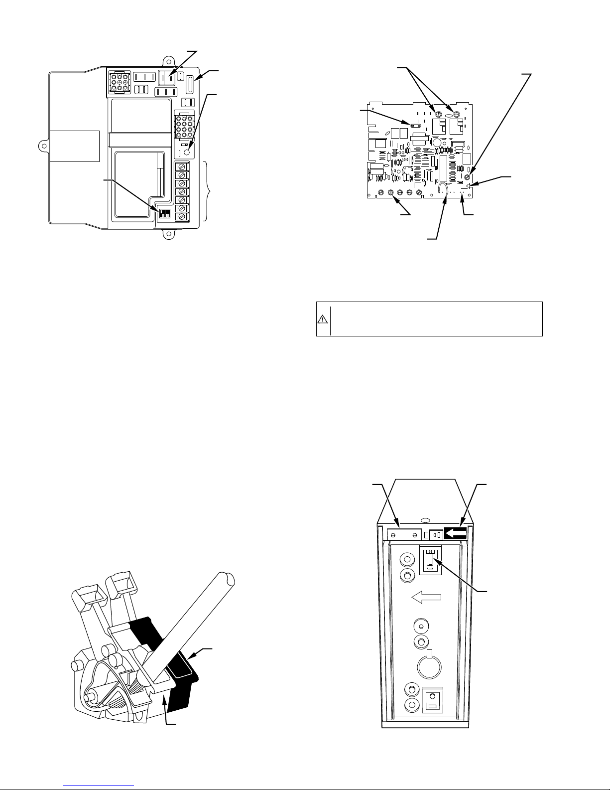
EAC - ELECTRONIC AIR CLEANER
(115-VAC 1 AMP MAX)
SEC-2
LED
HUM
GRY/Y2W/W1COM
24 V
W2
3-AMP
FUSE
LED -
DIAGNOSTIC
LIGHT
24-VOLT
THERMOSTAT
TERMINALS
FURNACE AND
BLOWER OFF
DELAY SETUP
SWITCHES
7 8 9
4 5 6
1 2 3
L2
PR2
L1
PR1
PARK
COM
EAC-2
EAC-1
3
FU1
-HEAT
-HEAT
HI-GAS
LO-GAS
HI-COOL
SEC-1
10 11 12
789
4 5 6
1 2 3
MASTER SLAVE
1
TWIN
TEST
1
1 2 3 4
OFF
ON
A94083
Fig. 21—EAC Connection to 2-Stage "C" Furnace Control
Board
ELECTRONIC
AIR CLEANER
TERMINALS
HUMIDIFIER TERMINAL
(24 VAC, 0.5 AMP MAX)
(115 VAC, 1 AMP MAX)
3
EAC-2 EAC-1
BLOWER OF DELAY SELF TEST
90 100 180 225
HUM-1
SELF-TEST PINS
JW9
3-AMP FUSE
W Y R C G
24-VOLT THERMOSTAT
TERMINALS
BLOWER OFF-DELAY
ADJUSTMENT CONTROL
A91060
Fig. 22—Internal Furnace Electrical Connections for EAC
d. Dry cells completely before turning on power to air
cleaner. This can be done by replacing cells in cabinet
and turning on system fan continuously for approximately 30 to 60 minutes before restoring power to air
cleaner.
e. With some dishwashers it may be necessary to re-run
complete cycle or rinse cycle after cells are removed if
homeowner notices dirt stains or residue inside dishwasher.
2. Manual Washing—The electronic cells may be washed
manually by soaking them in a solution of automatic
dishwasher detergent.
a. Provide suitable container large enough to hold one or
both cells.
b. Select automatic dishwasher detergent that dissolves
readily in hot water. Depending on local water conditions, some brands may form a precipitation or scum. If
a noticeable scum floats to surface, try another brand.
The brand the homeowner finds gives the best results in
the dishwasher will probably give best results washing
the electronic cells.
CAUTION: Do not splash detergent solution in eyes and
avoid prolonged contact with skin. Keep detergent and
solution out of reach of children.
c. Before placing cells in washing container, pour in
detergent. Use approximately 3/4 cup per cell if container is about size of cell. Add enough very hot water to
cover cell(s).
d. After detergent has completely dissolved, place elec-
tronic cell(s) in container.
e. Soak cells for 15 to 20 minutes, slosh several times, and
remove.
f. Rinse cells with fine water spray.
JUNCTION
BOX
COVER
AIR FLOW
AIRFLOW
DECAL
PROPER
SPRING
LOCATION
EAC2
Fig. 23—EAC Terminals on Control Center
EAC1
A94084
A89420
Fig. 24—Final Assembly Detail
—10—
Page 11
A91478
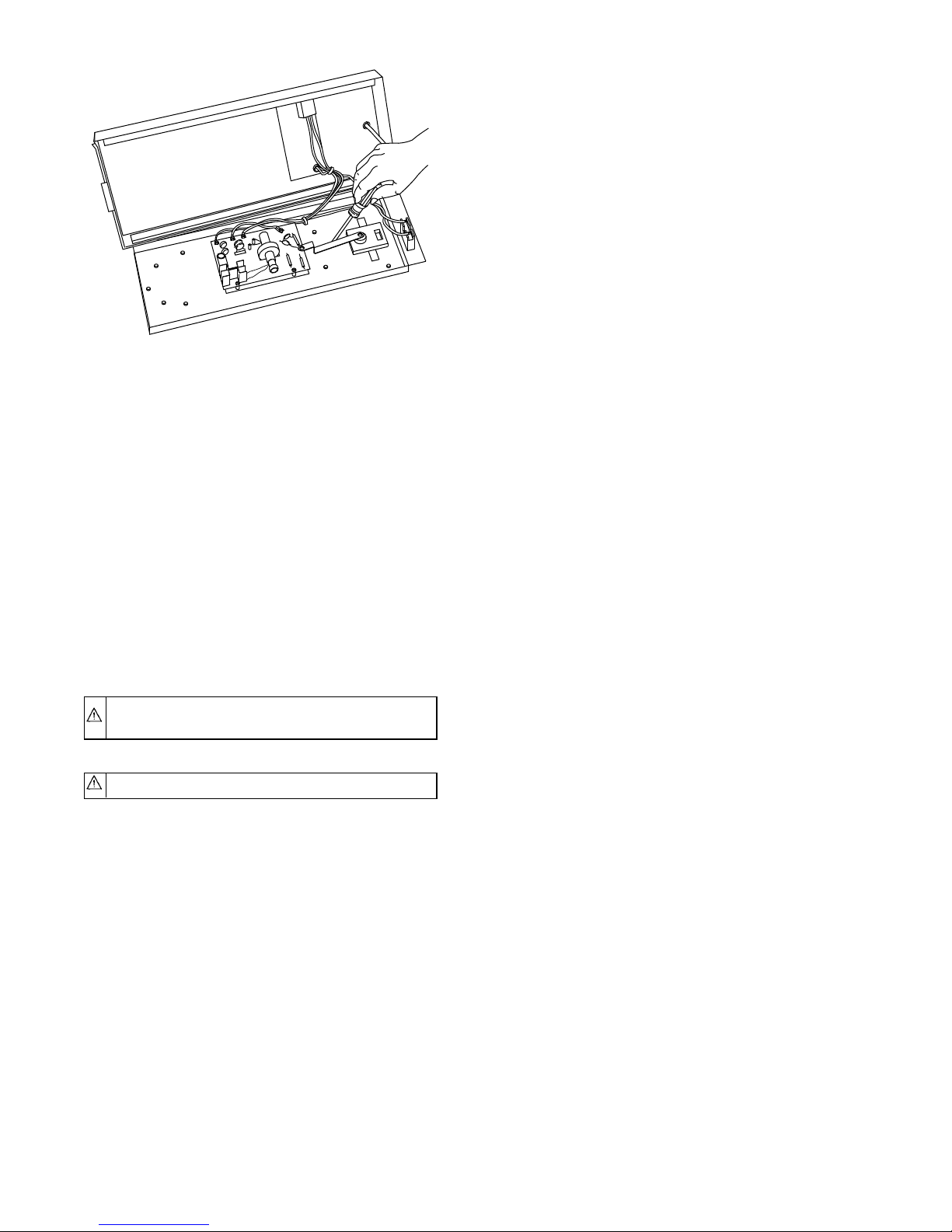
Fig. 25—Checking 120-V Power Pack
g. Fill wash container with clean, hot water and soak cell(s)
for 5 to 15 minutes.
h. Remove cell(s) and let water drain. If water draining
from them feels slippery, detergent still remains. Repeat
rinsing until water from them no longer feels slippery.
Inspect for cleanliness.
i. When both cells have been washed and thoroughly
rinsed, check cells for broken wires and bent collector
plates. If none are found, replace electronic cells and
pre-filter in cabinet. Observe proper airflow arrows on
cabinet and cells.
j. Dry cells completely before turning on power to air
cleaner. This can be done by turning on system fan
continuously for approximately 30 minutes before turning on power to air cleaner.
SERVICE GUIDE
CAUTION: Procedures in this section should be per-
formed only by qualified service personnel.
WARNING: Electrical shock can cause injury or death.
1. During troubleshooting procedures, dangerous line-voltage
circuits are exposed. Use care to avoid hazard of electrical
shock or damage to equipment.
2. Although not lethal, high-voltage output of power supply
can produce painful shock.
3. Be sure to properly ground air cleaner and its components
before testing.
4. Do not touch any portion of air cleaner when energized.
A. Tools and Equipment
Servicing the EAC can be accomplished with only a few tools:
1. Screwdrivers: Long shank, plastic or rubber handles (2
required).
2. Needle nose pliers for stringing ionizing wires.
3. High-voltage jumper cord.
4. High-voltage tester: range to 12 KVDC (DC voltage probe
recommended).
5. Grounding wire.
I. ELECTRICAL TROUBLESHOOTING GUIDE
The following troubleshooting procedure is a simplified approach
to aid service personnel in repairing any malfunction in the EAC.
By following this troubleshooting procedure and the operation
light, the malfunction can be isolated to certain areas in the EAC.
A. Normal Operation
For normal operation of an EAC, the system blower should be
running and the air cleaner switch should be ON. This will allow
the unit to be energized and cause the light on the power door to
glow. Occasional arcing by an EAC is normal (the light on the
power door will flicker). This can result when lint or large particles
of dirt are not stopped by the pre-filters. The dirtier the EAC
becomes, the more likely occasional arcing will occur. Continuous
arcing may indicate cleaning is necessary. The EAC should
operate only when the system blower is running.
B. Isolating Malfunctions
Switch on the EAC and energize the blower system. If the light
does not glow, remove the cells and replace the door. If the light
glows with the cells removed, the problem is within the cell or
cabinet. Proceed to items 1 through 3. However, if the light does
not glow, proceed to items 4 through 10.
It may be necessary to perform items 1 through 3 after completing
items 4 through 10.
1. Check spring on cell to see if it is bent, sprung, or deformed.
Check to see that it makes good contact with door. If not,
repair or replace.
2. Check male and female plug and receptacle and associated
wire connection on power door and cabinet for damage and
proper wiring.
3. Visually inspect air cleaner cells, visually inspecting for:
a. Heavy dirt accumulation (Wash cells—see Cleaning The
Cell section.)
b. Bent collector plates. Straighten, if necessary.
c. Ionizer springs broken or bent. Replace if necessary.
Check to see that ionizer springs are seated properly in
place. Improper seating may cause arcing.
d. Insulators cracked or broken. Replace if necessary.
Deterioration of metal around insulator indicates defec-
tive insulator (Replace insulator).
e. Ionizer grid deformed. Repair or replace as necessary.
Check for short between high-voltage contact (found in
center of rectangular ceramic insulator) and frame of
cell, with ohmmeter. Resistance should be infinite (open
circuit). If the light does not glow when cells are
removed:
4. Remove power door from unit and check for power to air
cleaner cabinet. This can be accomplished with a volt meter.
Being careful to avoid electrical shock, check output at the
receptacle with volt meter. Reading should be approximately 120v (240 for 240-v conversions).
During normal operation, power to the cabinet should only be
activated while system blower is operating. To avoid building up
an undesirable concentration of ozone DO NOT operate EAC
when blower is off.
5. Disconnect power and remove access panel on power door
and visually check to see that all wire connectors are firm
and that wires are not broken. Repair or replace with 18
gage wire minimum.
6. Inspect ceramic insulators for dirt or damage. Clean or
replace. Deterioration of metal around insulator indicates
defective insulator. Replace, as necessary.
Inspect for visual damage.
—11—
Page 12

BLOWER ON
ENERGIZE
UNIT
LIGHT OFF
LIGHT ON
UNIT
OPERATING
PROPERLY
IF CELLS
IN PLACE
REMOVE
CELLS
LIGHT OFF
CHECK:
WIRING
INSULATORS
POWER
SUPPLY
LIGHT IS ON
Fig. 26—Electrical Troubleshooting Flow Chart
WARNING: A possible shock hazard exists. Do not
allow arcing for a prolonged period of time. The power
supply output can be checked with a high-voltage voltmeter. The output should read between 9000 and 11000
vdc. If the output is below 7500 vdc, replace the power
supply.
7. Check switch and light circuit by applying electrical power
to plug on power door. This can be accomplished with
jumpers from cabinet receptacle. Attach grounding wire
between power door base and cabinet.
WARNING: A possible shock hazard exists. Be careful
not to short out the power supply. The buss bar and
contact plate carry live high voltage current on —
7300vdc, 1 MA.
CHECK CELLS
CONTACT
SPRING
CHECK LIGHT,
LIGHT
CIRCUIT
A91482
The LED light circuit output can be checked with a voltmeter. The
reading should be 4vac.
8. Check power supply.
a. Place screwdriver on ground plate (access panel). At the
same time move shank portion of screwdriver towards
high-voltage output of power supply. If arcing occurs
when screwdriver comes within approximately 1/8 in. of
power supply, power supply is operating properly. If no
arcing occurs, power supply is defective. Replace power
supply.
b. Use high voltage tester. Voltage output should be
between 9000 and 11000vdc.
—12—
Page 13
PROBLEM POSSIBLE CAUSES REMEDY
Operation light off
Unit snaps or arcs continuously
Humming noise
Air cleaner does not clean dirt
Radio or TV interference
White dust on furnishings
Ozone odor
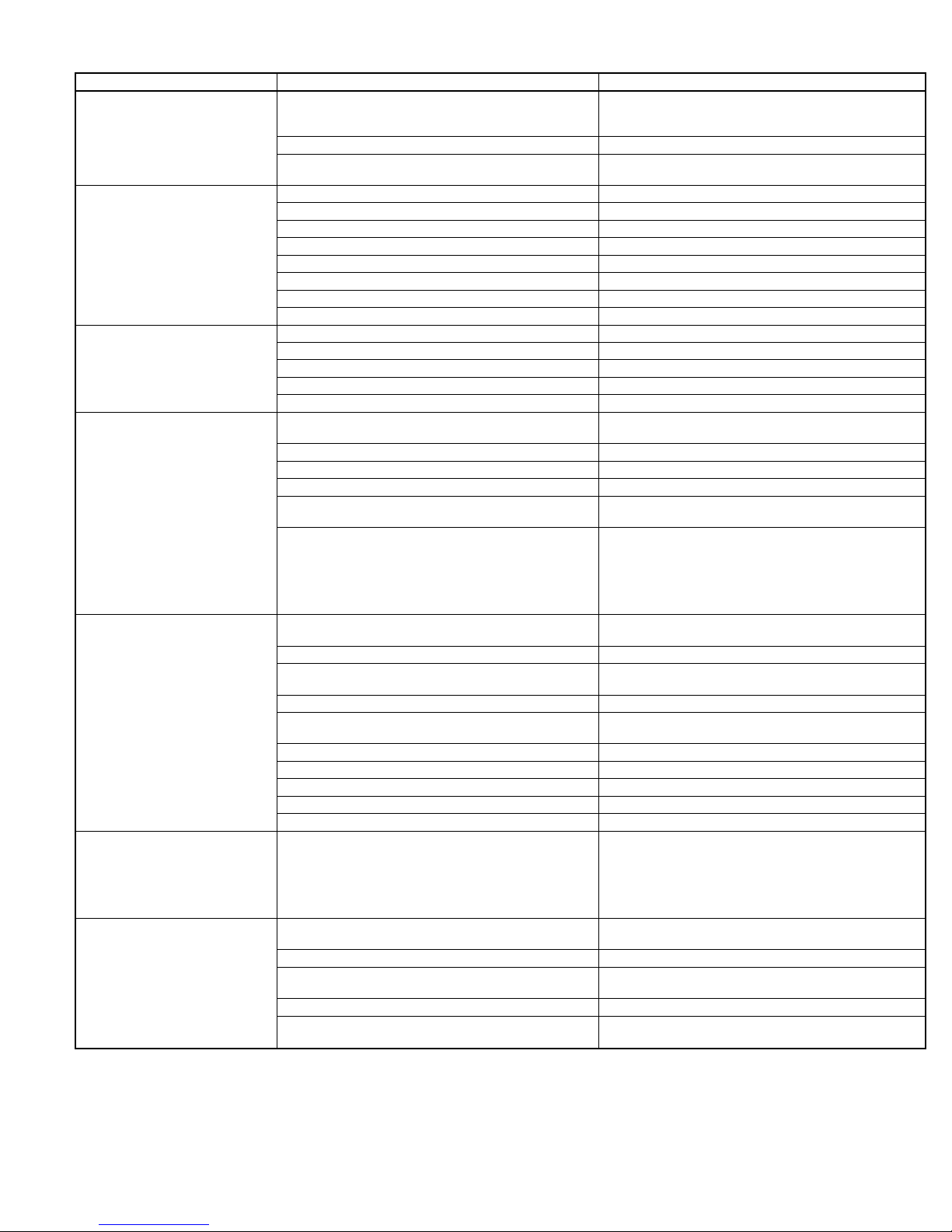
ELECTRICAL TROUBLESHOOTING FLOW CHART
Shorted cells.
Defective light.
Defective power supply.
Blower not operating. Energize blower.
Cells wet either due to high humidity or from washing.
Line voltage too high. Adjust line voltage.
Cells need cleaning. Clean cells.
Broken ionizer wire. Replace wire.
Broken contact spring on cell. Replace spring.
Broken insulator in cell. Replace insulator.
Broken insulator in power door. Replace insulator.
Foreign material lodged in ionizer or between plates. Remove object.
Bent plates. Straighten.
Improper wiring connections. Correct.
Loose ionizer wires. Replace or repair.
Ionizer wires not centered. Center wires between plates.
Excessively dirty ionizer or collector. Clean.
Deformed contact spring on cell. Adjust spring.
Lack of power to cells because of improper alignment of
contact spring cells to power door.
Defective interlock plug or receptacle. Replace.
Air volume too great. Reduce air volume to design CFM.
Leaks in ductwork on clean air side of air cleaner. Seal.
Dirty air not being delivered to air cleaner.
Uneven air distribution across face of unit may be indi-
cated by uneven loading pattern of dirt in collector section of air cleaning cells. The entering-air side of collector stage should be evenly covered with dirt. In the case
of the 2 cell units, each cell should have an even loading pattern.
Accumulation of foreign particles lodged in ionizer section
Unit improperly grounded. Provide good ground to power pack.
Ground line of supply line voltage not properly
grounded.
Loose ionizer wires. Replace.
Loosely connected components or primary-voltage wir-
ing.
Defective power pack. Replace.
Dents in collector section or ionizer section. Straighten.
Improper contact between power door and cells. Adjust alignment of contact spring.
Weak station/poor ground. Add E.M.I./R.F.I. filter in power line.
Defective insulator. Replace.
This dust can be described as "clean dirt" and is com-
posed mainly of lint, which, because of its weight settles
in the living space before it reaches the air returns. It is
"white" because the submicron dirt particles, which normally would color it and render it invisible, have been
removed from the air space.
Initial break-in period may have a noticeable ozone
odor.
Air volume too low. Increase air volume to design CFM.
Uneven air distribution across face of unit.
Air cleaner oversized for application. Size air cleaner per design CFM rating.
Air cleaner not shutting off during blower off cycle.
See Electrical Troubleshooting Guide section.
Dry cells by operating system fan continuously for 30
minutes.
Adjust alignment or replace spring.
Check return-air grilles for obstruction by furniture,
drapes, etc. Clean any obstruction.
Install turning vanes of air baffles.
CAUTION: Do not block off any of the entering-air side
opening to the unit.
Remove.
Correct.
Tighten.
This problem requires no solution. It is visible evidence
that the air cleaner is cleaning up the staining and soiling dirt particles from the living space.
See Maintenance and Routine Service section.
Ensure full opening of return-air is used. Do not block off
any part of return surface area.
Check wiring and ensure that the air cleaner does not
operate when blower is off.
—13—
Page 14

© 1994 BDP Co. • P.O. Box 70 • Indianapolis, IN 46206 Printed in U.S.A.
—14—
901k124 Catalog No. BDP-3390-107
 Loading...