

Page 1
installation, start-up and
service instructions
PACKAGED AIR
CONDITIONERS
IMPORTANT — READ BEFORE INSTALLING
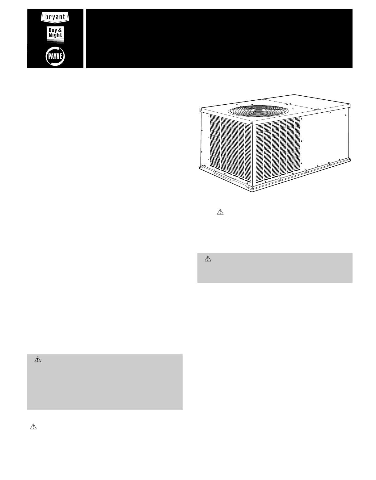
1. Read and become familiar with these installation instructions beforeinstallingthis unit (Fig. 1). Retain these
instructions for future maintenance and repair.
2. Be sure the installation conforms to all applicable local
and national codes. Wearsafety glasses and work gloves.
Use quenching cloth for unbrazing operations. Have fire
extinguisher available for all brazing operations.
564A
Sizes 024-060
764A
Sizes 024-060
Cancels: II 564A-24-1 II 564A-24-2
6/1/96
CONTENTS
SAFETY CONSIDERATIONS .......................1
INSTALLATION .................................1-11
I. Locate the Unit .............................5
II. Rig and Place Unit ..........................5
III. Unit Duct and Field Connections ..............5
PRE-START-UP ................................11,12
START-UP ....................................12,13
I. Heating Section Start-Up and Adjustments ....12
II. Cooling Section Start-Up and Adjustments ....12
III. Indoor Airflow and Airflow Adjustments .......13
CARE AND MAINTENANCE .......................14
I. Air Filter ..................................14
II. Evaporator Fan and Motor ..................14
SERVICE .....................................15-18
I. Cleaning .................................15
II. Evaporator Fan and Motor ..................15
III. Condenser Fan ............................15
IV. Electrical Controls and Wiring ...............16
V. Indoor Airflow .............................16
VI. Metering Device Servicing ..................16
VII. Liquid Line Strainer ........................16
VIII. Refrigerant Charge .........................16
IX. Replacement Parts .........................16
COOLING TROUBLESHOOTING CHART ............19
START-UP CHECKLIST ..........................CL-1
SAFETY CONSIDERATIONS
WARNING:
ation, service, maintenance, or use can cause explosion, fire, electric shock, or other occurrences which may
injure you or damage your property. Consult a qualified installer or service agency for information or assistance. The qualified installer or agency must use only
factory-authorized kits or accessories when modifying
this product.
Recognize safety information. This is the safety-alert symbol
( ). When you see this symbol on the unit and in instructions or manuals, be alert to the potential for personal
injury.
Understand the signal words — DANGER, WARNING, and
CAUTION. These words are used with the safety-alert
Improper installation, adjustment, alter-
Page
Fig. 1 — Unit 564A and 764A (Size 036 Shown)
symbol . Danger identifies the most serious hazards which
will result in severe personal injury or death. Warning indicates a condition that could result in personal injury.
Caution is used to identify unsafe practices which would
result in minor personal injury or product and property
damage.
WARNING:
tenance operations on system, turn off main power
switches to unit. Turnoff accessory heater power switch
if applicable. Electric shock can cause personal injury.
1. The power supply (volts, phase, and hertz) must correspond to that specified on unit rating plate.
2. The electrical supply provided by the utility must be sufficient to handle load imposed by this unit.
3. Refer to Installation, Locate the Unit section (page 5)
and Fig. 2-4 for locations of electrical inlets, condensate
drain, duct connections, and required clearances before
setting unit in place.
4. This installation must conform with local building codes
and with NEC (National Electrical Code) or NFPA
(National Fire Protection Association) 54 TIA-54-84-1.
Refer to provincial and local plumbing or wastewater codes
and other applicable local codes.
5. Approved for outdoor installation on wood flooring or on
class A, B, or C roof covering materials.
All units can be connected into existing duct systems that are
sized properly and designed to handle the airflow shown in
the Air Delivery table and Indoor Airflow and Airflow Adjustments section.
NOTE: When installing any accessory item, see the manufacturer’s installation instructions packaged with the accessory. Use factory-authorized kits or accessories when
modifying this unit.
Before performing service or main-
INSTALLATION
Page 2

UNIT
564A/764A
024 208/230-1-60 222 101 355.6 [14.00] 508.0 [20.00] 241.3 [9.50]
030 208/230-1-60 236 107 355.6 [14.00] 508.0 [20.00] 241.3 [9.50]
036 208/230-1-60, 208/230-3-60 250 114 355.6 [14.00] 508.0 [20.00] 241.3 [9.50]
ELECTRICAL
CHARACTERISTICS
UNIT
WEIGHT
Lb Kg X Y Z
CENTER OF GRAVITY mm [in.]
NEC — National Electrical Code
REQUIRED CLEARANCES TO COMBUSTIBLE
MATERIAL, mm [in.]
Top of Unit ..............................0
Duct Side of Unit ..........................0
Side Opposite Ducts ........................0
Bottom of Unit ............................0
NEC REQUIRED CLEARANCES, mm [in.]
Between Units, Power Entry Side .......1066.8 [42.00]
Unit and Ungrounded Surfaces,
Power Entry Side ................. 914.0 [36.00]
Unit and Block or Concrete Walls and Other
Grounded Surfaces, Power Entry Side ....1066.8 [42.00]
REQUIRED CLEARANCES FOR SERVICING, mm [in.]
Condenser Coil Access Side ............762.0 [30.00]
Power Entry Side
(Except for NEC Requirements) .........762.0 [30.00]
Unit Top ........................914.0 [36.00]
Side Opposite Ducts .................762.0 [30.00]
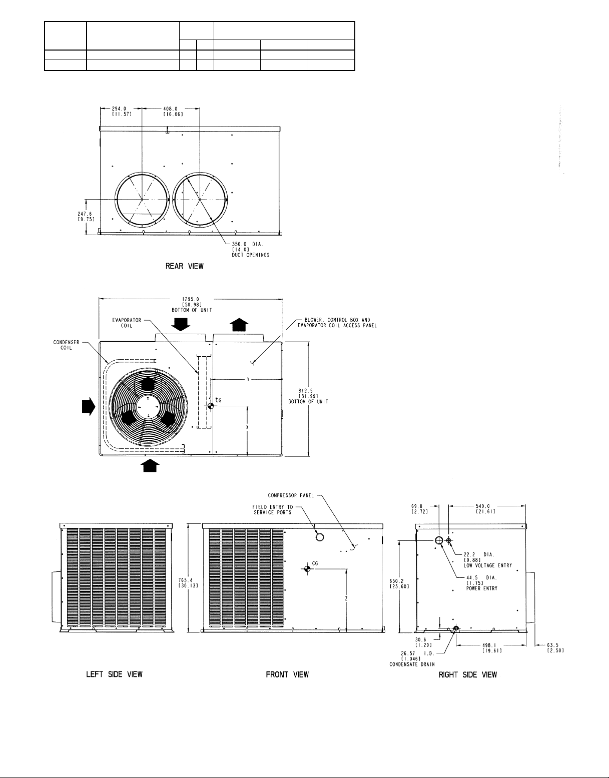
NOTES:
1. Clearances must be maintained to prevent recirculation of
air from condenser-fan discharge. With the exception of the
condenser coil (914 mm [36 in.]), a removable fence or barricade requires no clearance.
2. Dimensions are inmillimeters.Dimensionsin[ ] are in inches.
LEGEND
Fig. 2 — Base Unit Dimensions — 564A/764A024-036
—2—
Page 3
UNIT
564A/764A
042 208/230-1-60, 208/230-3-60 297 135 355.6 [14.00] 508.0 [20.00] 304.8 [12.00]
048 208/230-1-60, 208/230-3-60 310 114 355.6 [14.00] 508.0 [20.00] 304.8 [12.00]
ELECTRICAL
CHARACTERISTICS
UNIT
WEIGHT
Lb Kg X Y Z
CENTER OF GRAVITY mm [in.]
NEC — National Electrical Code
REQUIRED CLEARANCES TO COMBUSTIBLE
MATERIAL, mm [in.]
Top of Unit ..............................0
Duct Side of Unit ..........................0
Side Opposite Ducts ........................0
Bottom of Unit ............................0
NEC REQUIRED CLEARANCES, mm [in.]
Between Units, Power Entry Side .......1066.8 [42.00]
Unit and Ungrounded Surfaces,
Power Entry Side ................. 914.0 [36.00]
Unit and Block or Concrete Walls and Other
Grounded Surfaces, Power Entry Side ....1066.8 [42.00]
REQUIRED CLEARANCES FOR SERVICING, mm [in.]
Condenser Coil Access Side ............762.0 [30.00]
Power Entry Side
(Except for NEC Requirements) .........762.0 [30.00]
Unit Top ........................914.0 [36.00]
Side Opposite Ducts .................762.0 [30.00]
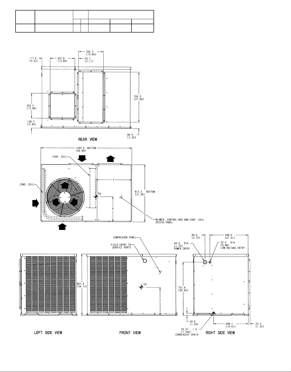
NOTES:
1. Clearances must be maintained to prevent recirculation of
air from condenser-fan discharge. With the exception of the
condenser coil (914 mm [36 in.]), a removable fence or barricade requires no clearance.
2. Dimensions are inmillimeters.Dimensionsin[ ] are in inches.
LEGEND
Fig. 3 — Base Unit Dimensions — 564A/764A042,048
—3—
Page 4
UNIT
564A/764A
060
ELECTRICAL
CHARACTERISTICS
230-1-60, 208/230-3-60,
460-3-60
UNIT
WEIGHT
Lb Kg X Y Z
350 159 355.6 [14.00] 508.0 [20.00] 355.6 [14.00]
CENTER OF GRAVITY mm [in.]
NEC — National Electrical Code
REQUIRED CLEARANCES TO COMBUSTIBLE
MATERIAL, mm [in.]
Top of Unit ..............................0
Duct Side of Unit ..........................0
Side Opposite Ducts ........................0
Bottom of Unit ............................0
NEC REQUIRED CLEARANCES, mm [in.]
Between Units, Power Entry Side .......1066.8 [42.00]
Unit and Ungrounded Surfaces,
Power Entry Side ................. 914.0 [36.00]
Unit and Block or Concrete Walls and Other
Grounded Surfaces, Power Entry Side ....1066.8 [42.00]
REQUIRED CLEARANCES FOR SERVICING, mm [in.]
Condenser Coil Access Side ............762.0 [30.00]
Power Entry Side
(Except for NEC Requirements) .........762.0 [30.00]
Unit Top ........................914.0 [36.00]
Side Opposite Ducts .................762.0 [30.00]
NOTES:
1. Clearances must be maintained to prevent recirculation of
air from condenser-fan discharge. With the exception of the
condenser coil (914 mm [36 in.]), a removable fence or barricade requires no clearance.
2. Dimensions are inmillimeters.Dimensionsin[ ] are in inches.
LEGEND
Fig. 4 — Base Unit Dimensions — 564A/764A060
—4—
Page 5
I. LOCATE THE UNIT
A. Clearance
Provide sufficient space for condenser airflow clearance, wiring, and servicing unit. See Fig. 2-4. Locate unit where supplyand return-air ducts can be conveniently brought out to unit
duct connections.
Unit may be placed with duct side as close to building
as top removal, duct connections, and power connections permit. Position unit so water or ice from roof does
not drop directly on top of unit or in front of coil. Make provisions for condensate drainage. Maintaina4ftclearance above
unit for vertical air discharge.
Roof installation method for units depends on building construction and special requirements of local building codes.
Be sure that roof can support unit weight.
Maintain clearance around and above unit to provide proper
airflow and service access. See Fig. 2-4.
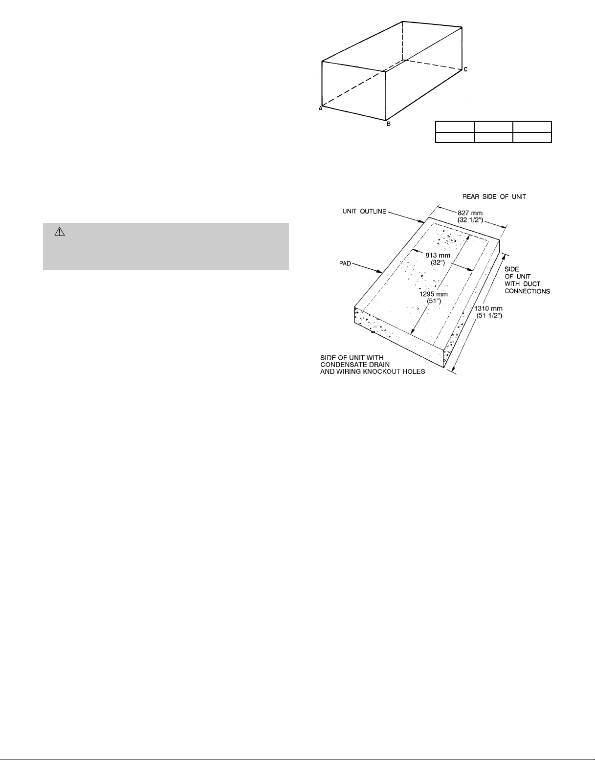
MAXIMUM ALLOWABLE
DIFFERENCE (in.)
A-B B-C A-C
1
⁄
4
1
⁄
4
Fig. 5 — Unit Leveling Tolerances
1
⁄
4
CAUTION:
Do not restrict condenser airflow. An air
restriction at either the condenser air inlet (the entire
surface of the condenser coil) or the fan discharge can
be detrimental to compressor life.
The condenser fan discharges through the top of the unit.
Ensure that the fan discharge does not recirculate to the condenser coil. Do not locate the unit either in a corner or under
a complete overhead obstruction, and ensure the following clearances are provided:
On roof overhangs, provide a minimum clearance of 48 in.
above the top of the unit for partial overhangs (such as a
normal house roof overhang). If there is a horizontal extension on the partial overhang, extension must not exceed
48 inches. For extended overhangs, provide a minimum clearance of 36 in. between unit and overhang.
Provide a minimum clearance of 42 in. for the control box
side next to a block wall or any other grounded surface. Provide a minimum clearance of 36 in. between the control box
side of the unit and any electrically live parts.
Unit may be installed on wood flooring, or on Class A, B, or C
roof covering materials.
Although unit is weatherproof, guard against water from higher
level runoff and overhangs.
Units should be at least 4 in. above the highest expected water,flood, and runoff levels. Do not use the unit if it has been
under water.
B. Ground-Level Installation
Mount unit on a solid, level pad. See Fig. 5 for unit leveling
tolerances. Construct pad as shown in Fig. 6. Side of unit with
condensate trap should be flush with pad for proper trap positioning (see Fig. 2-4). Extend a 24-in. gravel apron around
pad for condensate drainage.
II. RIG AND PLACE UNIT
Inspect unit for transportation damage. File any claim with
transportation agency. Keep upright and do not drop. Level
by using unit frame as a reference. See Table 1 for additional
information. Weight is shown in Fig. 2-4. Unit can be moved
with handholds provided in the unit basepan.
NOTES:
1. Extend a 24-in. gravel apron around pad.
2. Provide a 30-in. service clearance at front and rear sides of unit.
Fig. 6 — Pad Dimensions
III. UNIT DUCT AND FIELD CONNECTIONS
A. Condensate Disposal
NOTE: Ensure that condensate-water disposal methods com-
ply with local codes, restrictions, and practices.
3
Units remove condensate water through a
⁄4-in. ID hole lo-
cated on the control box side of the unit.
Condensate water can be drained directly onto a gravel apron
in ground-level installations. Install a field-supplied condensate trap at end of condensate connection to ensure proper
drainage. See Fig. 7. Make sure that the outlet of the trap is
at least 1 in. lower than the drain pan condensate connection
to prevent the pan from overflowing. See Fig. 8Aand 8B. Prime
the trap with water. When using a gravel apron, make sure
it slopes away from the unit.
—5—
Page 6

Table 1 — Physical Data
UNIT 564A AND 764A 024 030 036 042 048 060
OPERATING WEIGHT (lb) 222 236 250 297 310 350
COMPRESSOR TYPE Reciprocating
REFRIGERANT R-22
Charge (lb) 2.8 3.9 4.7 4.4 6.1 7.5
REFRIGERANT METERING DEVICE Acutrol™ System
CONDENSER COIL Copper Tubes, Aluminum Plate Fins
Rows...Fins/in. 1...17 1...17 2...17 1...17 2...17 2...17
Total Face Area (sq ft) 6.7 7.9 6.2 11.1 8.6 10.7
CONDENSER-FAN MOTOR Propeller
Cfm 1600 2000 2000 2600 2600 2800
Nominal Rpm 825 1100 1100 1100 1100 1100
Motor Hp
Diameter (in.) 20 20 20 20 20 20
EVAPORATOR COIL Copper Tubes, Aluminum Plate Fins
Rows...Fins/in. 2...15 3...15 3...15 3...15 3...15 4...15
Total Face Area (sq ft) 2.8 2.8 3.1 3.9 4.3 4.9
EVAPORATOR-FAN MOTOR Direct Drive
Blower Motor Size (in.) 10x8 10x8 10x8 10x9 10x9 10x10
Nominal Cfm 800 1000 1200 1400 1600 2000
Rpm Range 550-1000 550-1000 800-1050 800-1050 1000-1100 950-1100
Number of Speeds 3333 2 3*
Factory Speed Setting Low Med Low Med Low Low
Motor Hp
CONNECTING DUCT SIZES Round Square
Supply Air (in.) 14 13.9 x 13.9
Return Air (in.) 14 13.9 x 27.8
FIELD-SUPPLIED RETURN AIR FILTER†
Throwaway (in.) 24x24 24x24 24x24 24x24 24x30 24x30
*460-v motors are 2-speed only.
†Required filter sizes shown are based on the ARI (Air Conditioning and Refrigeration Institute)
rated airflow at a velocity of 300 ft/min for throwaway type or 450 ft/min for high capacity type.
Recommended filters are 1-in. thick.
1
⁄
8
1
⁄
4
1
⁄
4
1
⁄
4
1
⁄
4
1
⁄
2
1
⁄
4
1
⁄
2
1
⁄
4
3
⁄
4
1
⁄
4
1
CONDENSATE DRAIN HOLE
Fig. 7 — Condensate Connection Details
Fig. 8A — Condensate Trap (Using Tubing)
Fig. 8B — Condensate Trap (Using PVC Piping)
If the installation requires draining the condensate water
away from the unit, install a field-supplied 2-in. trap using
3
⁄4-in. OD tubing or piping to ensure proper drainage. See
Fig. 8A and 8B. Make sure that the outlet of the trap is at
least one in. lower than the unit drain pan condensate connection to prevent the pan from overflowing. Connect a drain
3
tube using a minimum of
⁄4-in. PVC,3⁄4-in. CPVC, or3⁄4-in.
copper pipe (all field-supplied).Do not undersize the tube. Pitch
the drain tube downward at a slope of at least 1 inch in every
10 ft of horizontal run. Be sure to check the drain tube for
leaks. Prime trap at the beginning of cooling season start-up.
Allowable glues for condensate trap connection are: Standard ABS, CPVC, or PVC cement.
B. Field-Duct Connections
NOTE: The design and installation of the duct system must
be in accordance with the standards of NFPA for the installation of nonresidence-type air conditioning and ventilating
systems, NFPA 90A or residence-type, NFPA 90B, and/or
local codes and ordinances.
Units have duct flanges on the supply- and return-air openings on the side of the unit. See Fig. 2-4 for connection sizes
and locations.
—6—
Page 7
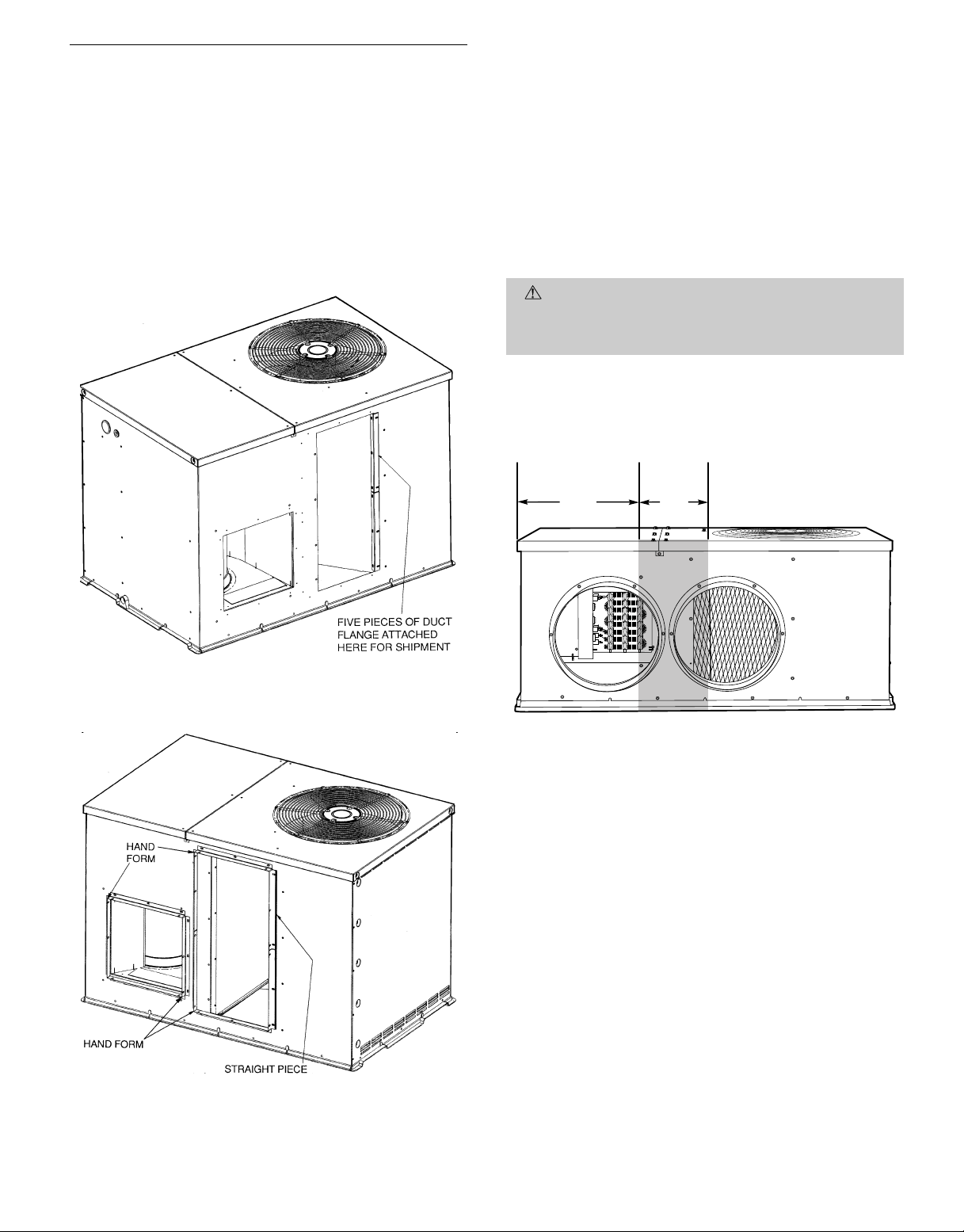
Install Flanges for Ductwork Connections (564A/764A060 only)
The size 060 units are shipped with flanges which must be
field-installed on the unit.
To install unit flanges:
1. Five pieces of flange are shipped on the return air opening of the unit. Remove the flanges from the shipping
position. See Fig. 9. Screws are field-supplied.
2. One piece of flange is used as it is shipped (straight).
Bend the other 4 pieces at right angles.
3. Install the straight flange on the right side of the return air opening in holes provided. See Fig. 10. Flanges
should stick out from unit to allow for connection of
ductwork.
4. Install 2 hand-formed flanges onto return air opening
in holes provided to form rectangle around the return
air opening.
5. Install remaining 2 hand-formed flanges around discharge air opening in holes provided.
6. Ductwork can now be attached to flanges.
Adhere to the following criteria when selecting, sizing, and
installing the duct system:
1. Select and size ductwork, supply-air registers, and returnair grilles according to ASHRAE (American Society of
Heating, Refrigeration, and Air Conditioning Engineers) recommendations.
Fig. 9 — Shipping Location of Duct Flanges
(Size 060 Only)
CAUTION:
When drilling the duct system fastening
holes into the side of the unit for duct flanges, do not
3
drill deeper than
⁄4in., and use extreme care not to
puncture the coil or coil tubes. See Fig. 11.
2. Use flexibletransition between rigid ductwork and unit
to prevent transmission of vibration. The transition may
be screwed or bolted to duct flanges. Use suitable gaskets to ensure weathertight and airtight seal.
19.17″ 3.92″
Fig. 11 — Area Not To Be Drilled More Than3⁄4-in.
Fig. 10 — Installation of Duct Flanges
(Size 060 Only)
3. Size ductwork for cooling air quantity (cfm).
4. Adequately insulate and weatherproof all ductwork
located outdoors. Insulate ducts passing through unconditioned space, and use vapor barrier in accordance
with latest issue of SMACNA (Sheet Metal and Air
Conditioning Contractors NationalAssociation) and ACCA
(Air Conditioning Contractors of America) minimum
installation standards for heating and air conditioning
systems. Secure all ducts to building structure.
5. Flash, weatherproof, and vibration-isolate all openings
in building structure in accordance with local codes and
good building practices.
6. Air filters should be installed in return-air ductwork.
Return-air filter grille or filter tracks in duct may be used.
Figure 12 shows a typical duct system with unit installed.
—7—
Page 8

LEGEND
NEC — National Electrical Code
*Required for electric heater when single-point connection is not
used.
Power Wiring
Control Wiring
Outdoor Airflow
Indoor Airflow
Fig. 12 — Typical Installation
C. Converting Horizontal Discharge Units to Downflow
(Vertical) Discharge
WARNING:
Before performing service or maintenance operations on system, turn off main power to unit.
Turnoffaccessory heater power switch if applicable. Electrical shock can cause personal injury.
Units are dedicated side-supply products. Units are not convertible to vertical air supply. A field-supplied plenum must
be used to convert to vertical air discharge.
D. Electrical Connections
WARNING:
The unit cabinet must have an uninterrupted, unbroken electrical ground to minimize the
possibility of personal injury if an electrical fault should
occur .This ground may consist of an electrical wire connected to the unit ground in the control compartment,
or conduit approved for electrical ground when
installed in accordance with NEC, ANSI (American
National Standards Institute)/NFPA (latest edition)
(in Canada, Canadian Electrical Code CSA [Canadian
StandardsAssociation] C22.1) and local electrical codes.
Failure to adhere to this warning could result in personal injury or death.
CAUTION:
Failure to follow these precautions could
result in damage to the unit being installed:
1. Make all electrical connections in accordance with
NECANSI/NFPA(latest edition) and local electrical
codes governing such wiring. In Canada, all electrical connections must be in accordance with CSA
Standard C22.1 Canadian Electrical Code Part 1
and applicable local codes. Refer to unit wiring
diagram.
2. Use only copper conductor for connections between
field-supplied electrical disconnect switch and unit.
DO NOT USE ALUMINUM WIRE.
3. Be sure that high-voltage power to unit is within operating voltage range indicated on unit rating plate.
On 3-phase units, ensure that phases are balanced
within 2%. Consult local power company for correction of improper voltage and/or phase imbalance.
4. Insulate low-voltage wires for highest voltage contained within conduit when low-voltage control wires
are run in same conduit as high-voltage wires.
5. Do not damage internal components when drilling
through any panel to mount electrical hardware, conduit, etc.
High-Voltage Connections
The unit must have a separate electrical service with a field-
supplied, waterproof disconnect switch mounted at, or within
sight from the unit. Refer to the unit rating plate for maximum fuse/circuit breaker size and minimum circuit amps
(ampacity) for wire sizing. See Table 2 for electrical data.
The field-supplied disconnect may be mounted on the unit over
the high-voltage inlet hole. See Fig. 2-4.
CAUTION:
Operation of unit on improper line voltage constitutes abuse and may causeunit damage that
could affect warranty.
Routing Power Leads Into Unit
Use only copper wire between disconnect and unit. The high-
voltage leads should be in a conduit until they enter the unit;
conduit termination at the unit must be watertight. Run the
high-voltage leads through the hole on the side of the unit
(see Fig. 13 for location). When the leads are inside the unit,
run leads to the control box (Fig. 14). For single-phase units,
connect leads to the black and yellow wires; for 3-phase units,
connect the leads to the black, yellow, and blue wires (see
Fig. 15).
Connecting Ground Lead to Unit Ground
Refer to Fig. 14 and 15. Connectthe ground lead to thechas-
sis using the unit ground screw in the control box.
Routing Control Power Wires
Form a drip-loop with the thermostat leads before routing
them into the unit. Route the thermostat leads through
grommeted hole provided in unit (see Fig. 13) into unit control box. Connect thermostat leads to unit control power leads
as shown in Fig. 16.
—8—
Page 9

Route thermostat wires through grommet providing a drip
loop at the panel. Connect low-voltage leads to the thermostat as shown in Fig. 16.
The unit transformer supplies 24-v power for complete
system including accessory electrical heater. Transformer is
factory wired for 230-v operation. If supply voltage is 208 v,
rewire transformer primary as described in Special Procedures for 208-V Operation section on page 11.
Accessory Electric Heat Wiring
Refer to accessory electric heat installation instructions for
information on installing accessory electric heat. Accessory
electric heat wiring is shown in Fig. 17.
HIGH-VOLTAGE
POWER WIRING
ENTRY HOLE
LOW-VOLTAGE
WIRING ENTRY
HOLE
Fig. 13 — Unit Electrical Connection Entry Holes
LEGEND
NEC — National Electrical Code
Field Control Wiring
Field Splice
Fig. 15 — Line Power Connections
Fig. 14 — Control Box Wiring
Fig. 16 — Control Connections
—9—
Page 10

Table 2 — Electrical Data
UNIT
564A/764A
024 208/230-1-60 187 254 10.9 61.0 0.9 2.4
030 208/230-1-60 187 254 15.2 69.4 1.5 2.4
036
042
048
060
FLA — Full Load Amps
HACR — Heating, Air Conditioning and
IFM — Indoor (Evaporator) Fan Motor
LRA — Locked Rotor Amps
MCA — Minimum Circuit Amps
MOCP — Maximum Overcurrent Protection
NEC — National Electrical Code
OFM — Outdoor (Condenser) Fan Motor
RLA — Rated Load Amps
*Heater capacity (kW) is based on heater voltage of 208 v, 240 v, or
480 v.If power distribution voltage to unit varies from rated heater voltage, heater
kW will vary accordingly.
†Fuse or HACR circuit breaker.
NOTES:
1. In compliance with NEC requirements for multimotor and combination load and
equipment (refer to NEC Articles 430 and 440), the overcurrent protective device for the unit shall be fuse or HACR breaker.
2. Unbalanced 3-Phase Supply Voltage
Never operate a motor where a phase imbalance in supply voltage is greater
than 2%.
imbalance.
% Voltage Imbalance
= 100 x
NOMINAL
VOLTAGE
(V-Ph-Hz)
208/230-1-60 187 254 15.9 86.0 1.5 2.8
208/230-3-60 187 254 8.9 64.5 1.5 2.8
208/230-1-60 187 254 18.5 97.6 1.5 2.8
208/230-3-60 187 254 10.9 73.0 1.5 2.8
208/230-1-60 187 254 21.3 107.0 1.5 4.2
208/230-3-60 187 254 12.3 73.0 1.5 4.2
230-1-60 207 254 26.9 128.0 1.4 6.2
208/230-3-60 187 254 17.7 128.0 1.4 6.2
460-3-60 414 508 9.0 63.0 0.7 3.2
LEGEND
Refrigeration
Use the following formula to determine the percentage of voltage
max voltage deviation from average voltage
average voltage
VOLTAGE
RANGE
Min Max RLA LRA FLA FLA
COMPRESSOR OFM IFM ELECTRIC HEAT POWER SUPPLY
DISCONNECT
Nominal
kW*
—/— —/— 16.9/ 16.9 20/ 20 16/ 16
7.5/10.0 36.1/41.7 48.1/ 55.1 50/ 60 44/ 51
—/— —/— 22.9/ 22.9 30/ 30 22/ 22
3.8/ 5.0 18.1/20.8 25.6/ 29.0 30/ 30 24/ 27
7.5/10.0 36.1/41.7 48.1/ 55.1 50/ 60 44/ 51
11.3/15.0 54.2/62.5 70.7/ 81.1 80/ 90† 65/ 75
—/— —/— 24.2/ 24.2 30/ 30 23/ 23
3.8/ 5.0 18.1/20.8 26.1/ 29.5 30/ 30 24/ 27
7.5/10.0 36.1/41.7 48.6/ 55.6 50/ 60 45/ 51
11.3/15.0 54.2/62.5 71.2/ 81.6 80/ 90† 66/ 75
15.0/20.0 72.2/83.3 93.6/107.7 100/110† 86/ 99
—/— —/— 15.4/ 15.4 20/ 20 15/ 15
3.8/ 5.0 10.4/12.0 16.5/ 18.5 20/ 20 15/ 17
7.5/10.0 20.8/24.1 29.6/ 33.6 30/ 35 27/ 31
11.3/15.0 31.3/36.1 42.6/ 48.6 45/ 50 39/ 45
15.0/20.0 41.7/48.1 55.6/ 63.6 60/ 70† 51/ 59
—/— —/— 27.4/ 27.4 35/ 35 26/ 26
3.8/ 5.0 18.1/20.8 27.4/ 29.5 35/ 35 26/ 27
7.5/10.0 36.1/41.7 48.6/ 55.6 50/ 60 45/ 51
11.3/15.0 54.2/62.5 71.2/ 81.6 80/ 90† 66/ 75
15.0/20.0 72.2/83.3 93.8/107.7 100/110† 86/ 99
—/— —/— 17.9/ 17.9 25/ 25 17/ 17
3.8/ 5.0 10.4/12.0 17.9/ 18.5 25/ 25 17/ 17
7.5/10.0 20.8/24.1 29.6/ 33.6 30/ 35 27/ 31
11.3/15.0 31.3/36.1 42.6/ 48.6 45/ 50 39/ 45
15.0/20.0 41.7/48.1 55.6/ 63.6 60/ 70† 51/ 59
—/— —/— 32.3/ 32.3 40/ 40 31/ 31
3.8/ 5.0 18.1/20.8 32.3/ 32.3 40/ 40 31/ 31
7.5/10.0 36.1/41.7 50.4/ 57.3 60/ 60 46/ 53
11.3/15.0 54.2/62.5 72.9/ 83.4 80/ 90† 67/ 77
15.0/20.0 72.2/83.3 95.5/109.4 100/110† 88/101
—/— —/— 21.1/ 21.1 25/ 25 21/ 21
3.8/ 5.0 10.4/12.0 21.1/ 21.1 25/ 25 21/ 21
7.5/10.0 20.8/24.1 31.3/ 35.3 35/ 40 29/ 32
11.3/15.0 31.3/36.1 44.3/ 50.4 45/ 60 41/ 46
15.0/20.0 41.7/48.1 57.4/ 65.4 60/ 70† 53/ 60
— — 41.2 50 40
5.0 20.8 41.2 50 40
10.0 41.7 59.8 60 55
15.0 62.5 85.9 90† 79
20.0 83.3 111.9 125† 103
—/— —/— 29.7/ 29.7 35/ 35 29/ 29
3.8/ 5.0 10.4/12.0 29.7/ 29.7 35/ 35 29/ 29
7.5/10.0 20.8/24.1 33.8/ 37.8 35/ 40 31/ 35
11.3/15.0 31.3/36.1 46.8/ 52.9 50/ 60 43/ 49
15.0/20.0 41.7/48.1 59.9/ 67.9 60/ 70† 55/ 62
— — 15.2 20 15
5.0 6.0 15.2 20 15
10.0 12.0 19.0 20 18
15.0 18.0 26.6 30 24
20.0 24.1 34.1 35 31
EXAMPLE: Supply voltage is 460-3-60
Determine maximum deviation from average voltage:
(AB) 457 − 452=5v
(BC) 464 − 457=7v
(AC) 457 − 455=2v
Maximum deviation is 7 v.
Determine percentage of voltage imbalance:
% Voltage imbalance = 100 x
This amount of phase imbalance is satisfactory as it is below the maximum
allowable 2%.
IMPORTANT: If the supply voltage phase imbalance is more than 2% contact
your local electric utility company immediately.
FLA MCA MOCP FLA LRA
AB = 452 v
BC = 464 v
AC = 455 v
Average voltage =
= 1.53%
452 + 464 + 455
3
= 457
7
457
SIZE
683.8/ 5.0 18.1/20.8 25.6/ 29.0 30/ 30 24/ 27
79
96
74
107
83
121
87
141
146
71
—10—
Page 11

Fig. 17 — Electric Heater Wiring
Special Procedures for 208-V Operation
WARNING:Make sure that the power supply to the
unit is switched OFF before making any wiring changes.
Electrical shock can cause personal injury or death.
1. Disconnect the orange transformer-primary lead from
the contactor. See unit wiring label.
2. Remove the wirenut from the terminal on the end of the
red transformer-primary lead.
3. Save the wirenut.
4. Connect the red lead to the contactor terminal from which
the orange lead was disconnected.
5. Using the wirenut removed from the red lead, insulate
the loose terminal on the orange lead.
6. Wrap the wirenut with electrical tape so that the metal
terminal cannot be seen.
Indoor blower-motor speeds may need to be changed for 208-v
operation. Refer to Indoor Airflow and Airflow Adjustments
section on page 13.
Heat Anticipator Setting
The room thermostat heat anticipator must be adjusted prop-
erly to ensure proper heating performance. Set anticipator
settings for room thermostat according to separate Accessory
Electric Heater Installation Instructions.
Failure to make a proper heat anticipator adjustment will
result in improper operation, discomfort to the occupants of
the conditioned space, and inefficientenergy utilization; however,the required setting may be changed slightly to provide
a greater degree of comfort for a particular installation.
E. Accessory Installation
At this time, any required accessories should be installed
on the unit. Refer to separate accessory installation
instructions.
PRE-START-UP
WARNING:
ings could result in serious personal injury:
1. Follow recognized safety practices and wear protective goggles when checking or servicing refrigerant
system.
2. Do not operate compressor or provide any electric
power to unit unless compressor terminal cover is in
place and secured.
3. Do not remove compressor terminal cover until all
electrical sources have been disconnected.
4. Relieve and reclaim all pressure from both high- and
low-pressure sides of the system before touching or
disturbing anything inside terminal box if refrigerant leak is suspected around compressor terminals.
5. Never attempt to repair soldered connection while
refrigerant system is under pressure.
6. Do not use torch to remove any component. System
contains oil and refrigerant under pressure. To remove a component, wear protective goggles and proceed as follows:
a. Turn off electrical power to unit.
b. Relieve and reclaim all pressure from system.
c. Cut component connecting tubing with tubing cut-
ter and remove component from unit.
d. Carefully unsweat remaining tubing stubs when
necessary. Oil can ignite when exposed to torch
flame.
For unit compressors equipped with accessory crankcase heaters, heaters are energized as long as there is power to the
unit. Energize crankcase heater 24 hours prior to unit startup. To energize heater only, set thermostat at OFF position
and turn on unit main power at disconnect switch.
Failure to observe the following warn-
—11—
Page 12

Proceed as follows to inspect and prepare the unit for initial
start-up:
1. Remove all access panels.
2. Read and follow instructions on all WARNING, CAUTION, and INFORMATIONlabels attached to, or shipped
with, unit.
3. Make the following inspections:
a. Inspect for shipping and handling damages such as
broken lines, loose parts, disconnected wires, etc.
b. Inspect for oil at all refrigerant tubing connections
and on unit base. Detecting oil generally indicates a
refrigerant leak. Leak-test all refrigerant tubing connections using electronic leak detector, halide torch,
or liquid-soap solution. If refrigerant leak is detected, see Repairing Refrigerant Leaks section on
page 15.
c. Inspect all field- and factory-wiring connections. Be
sure that connections are completed and tight.
d. Inspect coil fins. If damaged during shipping and han-
dling, carefully straighten fins with a fin comb.
4. Verify the following conditions:
a. Make sure that condenser fan blade is correctly po-
sitioned in fan orifice. Top edge of blade should be
3.125 in. from condenser outlet grille.
b. Make sure that air filter(s) is in place.
c. Make sure that condensate drain pan and trap are
filled with water to ensure proper drainage.
d. Make sure that all tools and miscellaneous loose parts
have been removed.
5. Compressors are internally spring mounted. Do not loosen
or remove compressor holddown bolts.
6. Each unit system has 2 Schrader-type ports, one lowside Schrader fitting located on the suction line, and one
high-side Schrader fitting located on the compressor discharge line. Be sure that caps on the ports are tight.
See Start-Up Checklist in back of book. Unit is now ready for
initial start-up.
START-UP
I. HEATING SECTION START-UP AND ADJUSTMENTS
(For units with accessory electric heaters.)
CAUTION:
in Pre-Start-Up section on this page before starting unit.
Do not jumper any safety devices when operating the unit.
A. Checking Heating Control Operation
Start and check the unit for proper heating control operation
as follows:
1. Turn on unit electrical supply.
2. Set system switch selector at HEAT position and fan switch
at AUTO. or ON position. Set heating temperature
lever above room temperature.
3. The evaporator fan and first-stage heat will start immediately. If unit is equipped with 2-stage heaters, secondstage heat will energize upon a call from W2. Check for
heating effect at supply diffusers.
Complete the required procedures given
4. After the call for heat has been satisfied, the evaporator
fan will stop. For units equipped with time-delay relay,
evaporator fan will stop after a 30-second time delay.
To shut off unit, set system selector switch at OFF position
or set heating set point lever below room temperature.
B. Heating Sequence of Operation
When power is supplied to unit, transformer (TRAN) is
energized.
With thermostat set to call for heating, sequence of operation
is as follows:
On a call for heat, circuit R-W and R-G are made through
first-stage thermostat bulb. If accessory electric heaters are
used, a relay is energized, bringing on first stage of supplemental electric heat and fan. When thermostat is satisfied,
contacts open, deenergizing relay (on all units) and timedelay relay (on units equipped with time-delay relay). Heaters deenergize, and evaporator fan stops after a 30-second
time delay (on units equipped with time-delay relay).
II. COOLING SECTION START-UP AND ADJUSTMENTS
CAUTION:
in Pre-Start-Up section, page 11, before starting the unit.
Do not jumper any safety devices when operating the
unit.
Do not operate the compressor when the outdoor tem-
perature is below 40 F (unless accessory low ambient
kit is installed).
Do not rapid-cycle the compressor.
A. Checking Cooling Control Operation
Start and check the unit for proper cooling control operation
as follows:
1. Place room thermostat SYSTEM switch in OFF position. Observe that evaporator-fanmotor starts when FAN
switch is placed in ON position and shuts down after a
30-second time delay when FANswitchis placed in AUTO.
position.
2. Place SYSTEM switch in COOL position and FANswitch
in AUTO. position. Set cooling control below room temperature. Observe that compressor, condenser fan, and
evaporator-fan motors start. Observe that cooling cycle
shuts down when control setting is satisfied. Evaporatorfan motor has off-delay (on units equipped with timedelay relay) of approximately 30 seconds on shutdown.
3. When using an auto. changeover room thermostat, place
both SYSTEM and FAN switches in AUTO. positions.
Observe that unit operates in Heating mode when temperature control is set to ‘‘call for heating’’ (above room
temperature) and operates in Cooling mode when temperature control is set to ‘‘call for cooling’’ (below room
temperature).
B. Checking and Adjusting Refrigerant Charge
The refrigerant system is fully charged with R-22 refrigerant, and is tested and factory-sealed.
NOTE: Adjustment of the refrigerant charge is not required
unless the unit is suspected of not having the proper R-22
charge. See Refrigerant Charge section on page 16 for further details.
Complete the required procedures given
—12—
Page 13

C. Unit Controls
Compressor
High-Pressure Relief Valve — Valve is located in compressor.
Relief valve opens at a pressure differential of approximately
450 psi between suction (low side) and discharge (high side)
to allow pressure equalization.
Internal Current and Temperature Sensing Overload —
Device resets automatically when internal compressor motor
temperature drops to a safe level. When an internal overload
is suspected of being open, check by using an ohmmeter or
continuity tester.
D. Cooling Sequence of Operation
NOTE: With the FAN switch in the ON position, 24 vis sup-
plied to the time-delay relay (TDR) through the G terminal
on the thermostat. This voltage energizes the coil of the relay, closing the normally-open set of contacts which provide
continuous power to the indoor (evaporator) fan motor (IFM).
Moving the FAN switch back to the AUTO. position (providing there is not a call for cooling) deenergizes the TDR (when
applicable) which deenergizes the IFM after a 30-second delay. The FAN switch inAUTO. position cycles upon a call for
cooling.
On a call for cooling, 24 v is supplied to the compressor contactor (C) and TDR simultaneously through theY and G terminals of the thermostat, respectively. On units with a compressor TDR, there is a built-in, 5-minute (±45 seconds) delay
between compressor starts. Energizing the contactor closes
the normally-open set of contacts supplying power to both the
compressor and outdoor (condenser) fan motor (OFM). Energizing the TDR closes the normally-open set of contacts providing power to the IFM. On the loss of the call for cooling,
24 v is removed from both the Y and G terminals of the thermostat (providing the FAN switch is in the AUTO. position),
deenergizing both the compressor and TDR and opening both
the contacts supplying power to compressor and OFM. IFM
has a 30-second delay.
III. INDOOR AIRFLOW AND AIRFLOW ADJUSTMENTS
Table 3 — Dry Coil Air Delivery —
Horizontal Discharge
UNIT
564A/764A
024
030
036
042
048†
060
ESP — External Static Pressure
IFM — Indoor (Evaporator) Fan Motor
*Unit is factory set on medium speed, this airflow is not obtainable at
low speed.
†Size 048 has low and high speed only.
**460 volt motors do not have a medium speed.
NOTE: Values for 208/230-v motors are at 230 v; deduct 10% for 208 v.
IFM SPEED
SETTING
Low 800 0.30 282
Med 800 0.65 349
High 800 0.80 439
Low* 1000 — —
Med 1000 0.35 370
High 1000 0.65 460
Low 1200 0.30 445
Med 1200 0.50 480
High 1200 0.65 530
Low* 1400 — —
Med 1400 0.30 495
High 1400 0.60 571
Low 1600 0.50 650
————
High 1600 0.65 720
Low 2000 0.15 900
Med** 2000 0.60 850
High 2000 0.65 945
LEGEND
AIRFLOW
(Cfm)
ESP
(in. wg)
POWER
(Watts)
A. For 208/230-v Blower Motors:
The motor leads are color-coded as follows:
3-SPEED 2-SPEED
black = high speed black = high speed
blue = medium speed red = low speed
red = low speed
CAUTION:
For cooling operation, the recommended
airflow is 350 to 450 cfm per each 12,000 Btuh of rated
cooling capacity.
Table 3 shows dry coil air delivery for horizontal discharge
units.
WARNING:
Disconnect electrical power to the unit before changing blower speed. Electrical shock can cause
personal injury or death.
Airflow can be changed by changing the lead connections of
the blower motor.
Units 564A/764A024, 036, 048, and 060 blower motors are
factory wired for low speed operation. Units 564A/764A030
and 042 are factory wired for medium speed operation.
To change the speed of the blower motor, remove the fan motor speed leg lead from the indoor (evaporator) fan relay (IFR)
and replace with lead for desired blower motor speed. Insu-
late the removed lead to avoid contact with chassis parts.
B. For 460-v (2-Speed) Blower Motors:
The motor leads are color coded as follows:
black = high
yellow = jumper
purple = jumper
red = low
To change the speed of the blower motor from low speed to
high speed, remove the red lead from the indoor fan relay
(IFR). Insulate the red lead to avoid contact with any chassis
parts. Separate the black lead from the purple jumper. Connect the black lead to the IFR. Insulate the purple lead to
avoid contact with any chassis parts.
—13—
Page 14

CARE AND MAINTENANCE
NOTE: The following steps should be performed by a quali-
fied service person.
WARNING:
off main power to system to avoid shock hazard or injury from rotating parts. There may be more than one
disconnect switch. Turnoff accessory heater power if applicable. Electrical shock can cause personal injury or
death.
To ensure continuing high performance, and to reduce the possibility of premature equipment failure, periodic maintenance must be performed on this equipment. Unit should
be inspected at least once each year by a qualified service
person.
NOTE TO EQUIPMENT OWNER: Consult your local dealer
about the availability of a maintenance contract.
WARNING:
nance on this equipment requires certain expertise,
mechanical skills, tools, and equipment. If you do not
possess these, do not attempt to perform any maintenance on this equipment other than those procedures
recommended in the User’sManual. FAILURETO HEED
THIS WARNINGCOULD RESULTIN SERIOUS PERSONAL INJURY AND POSSIBLEDAMAGE TO THIS
EQUIPMENT.
The minimum maintenance requirements for this equipment
are as follows:
1. Inspect air filter(s) each month. Clean or replace when
necessary.
2. Inspect condensing coil, drain pan, and condensate drain
each cooling season for cleanliness. Clean when
necessary.
3. Inspect evaporator-fan motor and wheel for cleanliness
each heating and cooling season. Clean when necessary.
For first heating season, inspect evaporator-fan motor
bimonthly to determine proper cleaning frequency.
4. Check electrical connections for tightness and controls
for proper operation each heating and cooling season.
Service when necessary.
5. Check the drain channel in the top cover periodically
for blockage (leaves, insects). Clean as needed.
WARNING:
sult in serious personal injury:
1. Turn off all electrical power to the unit before performing any maintenance or service on the unit.
2. Use extreme caution when removing panels and parts.
As with any mechanical equipment, personal injury
can result from sharp edges, etc.
3. Never place anything combustible either on, or in contact with, the unit.
4. Should overheating occur, shut off all of the electrical supply(s).
Before installing or servicing unit, turn
The ability to properly perform mainte-
Failure to follow these warnings could re-
I. AIR FILTER
CAUTION:
able air filter in the return-air duct system.Always replace the filter with the same dimensional size and type
as originally installed. See Tables 1 and 2 for recommended filter sizes.
Inspect air filter(s) at least once each month and replace
(throwaway-type) or clean (permanent-type) at least twice during each cooling season or whenever the filter(s) becomes clogged
with dust and lint.
II. EVAPORATOR FAN AND MOTOR
NOTE: Motors without oilers are permanently lubricated. Do
not attempt to lubricate these motors.
For longer life, operating economy, and continued efficiency,
clean accumulated dirt and grease from the evaporator-fan
wheel and motor annually.
Lubricate the motor every 5 years if the motor is used intermittently (thermostat FAN switch in AUTO. position), or
every 2 years if the motor is used continuously (thermostat
FAN switch in ON position).
WARNING:
the unit before cleaning the evaporator-fan and wheel.
Failure to adhere to this warning could cause personal
injury or death.
To clean the blower wheel:
1. Access the blower assembly as follows:
a. Remove top access panel.
b. Remove 3 screws that hold blower orifice ring to blower
housing. Save screws.
c. Loosen set screw(s) which secure wheel to motor shaft.
2. Remove and clean blower wheel as follows:
a. Lift wheel from housing. When handling and/or clean-
ing blower wheel, be sure not to disturb balance weights
(clips) on blower wheel vanes.
b. Remove caked-on dirt from wheel and housing with
a brush. Remove lint and/or dirt accumulations from
wheel and housing with vacuum cleaner, using a soft
brush attachment. Remove grease and oil with a mild
solvent.
c. Reassemble blower into housing. Place upper orifice
ring on blower to judge location of the blower wheel.
Blower wheel should be approximately .2 in. below
bottom of orifice ring when centered correctly.Be sure
set screws are tightened on motor and are not on round
part of shaft.
d. Set upper orifice ring in place with 3 screws removed
in Step 1.
e. Replace top access panel.
Never operate the unit without a suit-
Disconnect and tag all electrical power to
—14—
Page 15

SERVICE
NOTE: The following steps should be performed by a quali-
fied service person.
Inspect the condenser coil, evaporator coil, and condensate
drain pan at least once each year.Proper inspection and cleaning requires the removal of the unit top. See Unit Top
Removal section above.
WARNING:
off main power to system to avoid shock hazard or injury from rotating parts. There may be more than one
disconnect switch. Turn off accessory heater power if
applicable. Electrical shock can cause personal injury
or death.
I. CLEANING
Inspect unit interior at the beginning of each heating and cooling season or as operating conditions require. To inspect and
clean, the unit top must be removed.
A. Unit Top Removal
NOTE: When performing maintenance orservice procedures
that require removal of the unit top, be sure toperform all of
the routine maintenance procedures that require top removal, including: coil inspection and cleaning, and condensate drain pan inspection and cleaning.
Only qualified service personnel should perform maintenance and service procedures that require unit top removal.
Refer to the following top removal procedures:
1. Remove 7 screws on unit top cover surface. Save all screws.
2. Remove 2 screws that secure unit top cover flange. Save
all screws.
3. Lift top from unit carefully. Set top on edge and ensure
that top is supported by unit side that is opposite duct
side.
When maintenance and/or service procedures are concluded,
carefully replace and secure unit top to unit, using screws removed in Steps 1 and 2.
B. Repairing Refrigerant Leaks
Proceed as follows to repair a refrigerant leak and to charge
the unit.
1. Locate leak and ensure that refrigerant system pressure has been relieved and recovered from both highand low-pressure ports.
2. Repair leak following accepted practices.
NOTE: Install a filter drier whenever the system has been
opened for repair.
3. Add a small charge of nitrogen vapor to system and leaktest unit.
4. Evacuate refrigerant system if additional leaks are not
found.
5. Charge unit with R-22 refrigerant, using a volumetriccharging cylinder or accurate scale. Refer to unit rating
plate for required charge. Be sure to add extra refrigerant to compensate for internal volume of filter drier.
NOTE: See Adjusting Refrigerant Charge on page 16.
Before installing or servicing unit, turn
The coils are easily cleaned when dry; therefore, inspect and
clean the coils either before or after each cooling season.
Remove all obstructions (including weeds and shrubs) that
interfere with the airflow through the condenser coil. Straighten
bent fins with a fin comb. If coated with dirt or lint, clean the
coils with a vacuum cleaner, using a soft brush attachment.
Be careful not to bend the fins. If coated with oil or grease,
clean the coils with a mild detergent-and-water solution. Rinse
coils with clear water, using a garden hose. Be careful not to
splash water on motors, insulation, wiring, or air filter(s). For
best results, spray condenser-coil fins from inside to outside
the unit. On units with an outer and inner condenser coil, be
sure to clean between the coils. Be sure to flush all dirt and
debris from the unit base.
Inspect the drain pan and condensate drain line when
inspecting the coils. Clean the drain pan and condensate drain
by removing all foreign matter from the pan. Flush the pan
and drain tube with clear water. Do not splash water on the
insulation, motor, wiring, or air filter(s). If the drain tube is
restricted, clear it with a ‘‘plumbers snake’’ or similar probe
device. Ensure that the auxiliary drain port above the drain
tube is also clear.
II. EVAPORATOR FAN AND MOTOR
Refer to Care and Maintenance section for procedure.
III. CONDENSER FAN
CAUTION:
obstructions to ensure proper cooling operation. Never
place articles on top of the unit. Damage to unit may
result.
1. Shut off unit power supply.
2. Remove condenser-fanassembly (grille, motor,motor cover,
and fan) by removing screws and flipping assembly onto
unit top cover.
3. Loosen fan hub setscrews.
4. Adjust fan height as shown in Fig. 18.
5. Tighten setscrews.
6. Replace condenser-fan assembly.
Keep the condenser fan free from all
C. Condenser Coil, Evaporator Coil, and Condensate
Drain Pan
WARNING:
hands with gloves when cleaning or handling coil.
Be careful! Coil fins are sharp. Protect
Fig. 18 — Condenser-Fan Adjustment
—15—
Page 16

IV. ELECTRICAL CONTROLS AND WIRING
Inspect and check the electrical controls and wiring annually. Be sure to turn off all electrical power to the unit.
Remove the control, evaporator fan, and compressor compartment access panels to locate all the electrical controls and
wiring. Check all electrical connections for tightness. Tighten
all screw connections. If any smoky or burned connections are
noticed, disassemble the connection and clean all the parts.
Then restrip the wire end, and reassemble the connection properly and securely.
After inspecting the electrical controls and wiring, replace all
the panels. Start the unit, and observe at least one complete
heating cycle (if accessory electric heaters are field installed
in unit) and one complete cooling cycle to ensure proper
operation. If discrepancies are observed in either or both
operating cycles, or if a suspected malfunction has occurred,
check each electrical component with the proper electrical
instrumentation. Refer to unit wiring labelwhen performing
these checkouts.
NOTE: Refer to the Cooling Sequence of Operation on
page 13 as an aid in determining proper control operation.
V. INDOOR AIRFLOW
The airflow does not require checking unless improper performance is suspected. If a problem exists, be sure that all
supply- and return-air grilles are openand free from obstructions, and that the air filter is clean. When necessary, refer
to Indoor Airflow and Airflow Adjustments section on
page 13 to check the system airflow.
VI. METERING DEVICE SERVICING
Refrigerant metering devices are fixed orifices and are located in the inlet header to the evaporator coil.
VII. LIQUID LINE STRAINER
Strainer is made of wire mesh and is located in the liquid
line on inlet side. Remove strainer by cutting it from the liquid line. Braze a new strainer into liquid line with nitrogen
gas flowing through the refrigerant system.
VIII. REFRIGERANT CHARGE
WARNING:
to prevent a burn when working on compressor.
CAUTION:
glasses and gloves when handling refrigerant.
Do not overcharge system.An overcharge can cause com-
pressor damage.
Avoidcontact with hot gas discharge line
To prevent personal injury, wear safety
A. Adjusting Refrigerant Charge
Amount of refrigerant charge is listed on unit nameplate (also
refer to Table 1). Refer to Carrier Refrigerant Service Techniques Manual, Refrigerants section.
Unit panels must be in place when unit is operating during
charging procedure.
No Charge
Use standard evacuating techniques. After evacuating
system, weigh in the specified amount of refrigerant(refer to
Table 1).
Low Charge Cooling
Use Cooling Charging Charts, Fig. 19-24. Varyrefrigerant un-
til the conditions of the appropriate chart are met. Note that
charging charts are different from the type normally used.
Charts are based on charging the units to the correct superheat for the various operating conditions. Accurate pressure
gage and temperature sensing device are required.
To measure suction pressure, perform the following:
1. Connect the pressure gage to the service port on the suction line.
2. Mount the temperature sensing device on the suction
line and insulate it so that outdoor ambient temperature does not affect the reading. Indoor-air cfm must be
within the normal operating range of the unit.
To Use Cooling Charging Charts
1. Take the outdoor ambient temperature and read the suction pressure gage.
2. Refer to appropriate chart to determine what the suction temperature should be.
3. If suction temperature is high, add refrigerant. If suction temperature is low, carefully recover some of the
charge.
4. Recheck the suction pressure as charge is adjusted.
EXAMPLE: (Fig. 19)
Outdoor Temperature ...........................85F
Suction Pressure .............................80psig
Suction Temperature should be ...................70F
(Suction Temperature may vary ± 5° F.)
If Chargemastert charging device is used, temperature and
pressure readings must be accomplished using the charging
chart.
Unit refrigerant system is factory charged. When recharging
is necessary, weigh in total charge indicated on unit nameplate. Remove and recover any refrigerant remaining in
system before recharging. If system has lost complete charge,
evacuate system to 500 microns (29.90-in. Hg vacuum) before recharging. Schrader fitting connections are provided on
unit suction and discharge lines for evacuation and charging. Dial-a-Charge charging cylinder is an accurate device used
to charge systems by weight; these cylinders are availableat
refrigeration supply firms.
IX. REPLACEMENT PARTS
A complete list of replacement parts may be obtained from
your distributor upon request.
—16—
Page 17

Fig. 19 — Cooling Charging Chart — 564A/764A024
Fig. 21 — Cooling Charging Chart — 564A/764A036
Fig. 20 — Cooling Charging Chart 564A/764A030
Fig. 22 — Cooling Charging Chart — 564A/764A042
—17—
Page 18

Fig. 23 — Cooling Charging Chart — 564A/764A048
Fig. 24 — Cooling Charging Chart — 564A/764A060
—18—
Page 19

COOLING TROUBLESHOOTING CHART
SYMPTOM CAUSE REMEDY
Compressor and condenser fan will not
start.
Compressor will not
start but condenser
fan runs.
Compressor cycles
(other than normally
satisfying thermostat).
Compressor operates
continuously.
Excessive head
pressure.
Head pressure too low. Low refrigerant charge Check for leaks, repair and recharge.
Excessive suction
pressure.
Suction pressure too
low.
Power failure Call power company.
Fuse blown or circuit breaker tripped Replace fuse or reset circuit breaker.
Defective thermostat, contactor, transformer,
or control relay
Insufficient line voltage Determine cause and correct.
Incorrect or faulty wiring Check wiring diagram and rewire correctly.
Thermostat setting too high Lower thermostat setting below room temperature.
Faulty wiring or loose connections in
compressor circuit
Compressor motor burned out, seized, or
internal overload open
Defective run/start capacitor, overload, or
start relay
One leg of 3-phase power dead Replace fuse or reset circuit breaker.
Refrigerant overcharge or undercharge Recover refrigerant, evacuate system, and recharge
Defective compressor Replace and determine cause.
Insufficient line voltage Determine cause and correct.
Blocked condenser Determine cause and correct.
Defective run/start capacitor, overload,
or start relay
Defective thermostat Replace thermostat.
Faulty condenser-fan motor or capacitor Replace.
Restriction in refrigerant system Locate restriction and remove.
Dirty air filter Replace filter.
Unit undersized for load Decrease load or increase unit size.
Thermostat set too low Reset thermostat.
Low refrigerant charge Locate leak, repair, and recharge.
Leaking valves in compressor Replace compressor.
Air in system Recover refrigerant, evacuate system, and recharge.
Condenser coil dirty or restricted Clean coil or remove restriction.
Dirty air filter Replace filter.
Dirty condenser coil Clean coil.
Refrigerant overcharged Recover excess refrigerant.
Air in system Recover refrigerant, evacuate system, and recharge.
Condenser air restricted or air short-cycling Determine cause and correct.
Compressor valves leaking Replace compressor.
Restriction in liquid tube Remove restriction.
High heat load Check for source and eliminate.
Compressor valves leaking Replace compressor.
Refrigerant overcharged Recover excess refrigerant.
Dirty air filter Replace filter.
Low refrigerant charge Check for leaks, repair, and recharge.
Metering device or low side restricted Remove source of restriction.
Insufficient evaporator airflow Increase air quantity. Check filter, and replace if
Temperature too low in conditioned area Reset thermostat.
Outdoor ambient below 40 F Install low-ambient kit.
Field-installed filter-drier restricted Replace.
Replace component.
Check wiring and repair or replace.
Determine cause. Replace compressor.
Determine cause and replace.
Determine cause.
to capacities shown on nameplate.
Determine cause and replace.
necessary.
—19—
Page 20

Page 21

Page 22

PACKAGED SERVICE TRAINING
Our packaged service training programs provide an excellent way to increase your knowledge of the
equipment discussed in this manual. Product programs cover:
• Unit Familiarization
• Installation Overview
• Maintenance
• Operating Sequence
A large selection of product, theory, and skills programs is available. All programs include a video
cassette and/or slides and a companion booklet. Use these for self teaching or to conduct full training
sessions.
For a free Service Training Material Catalog (STM), call 1-800-962-9212. Ordering instructions are
included.
Copyright 1996 Carrier Corporation CATALOG NO. BDP-3356-403
Page 23

Page 24

I. PRELIMINARY INFORMATION
START-UP CHECKLIST
(Remove and Store in Job File)
MODEL NO.:
DATE:
SERIAL NO.:
TECHNICIAN:
II. PRE-START-UP (insert checkmark in box as each item is completed)
M VERIFY THAT ALL PACKING MATERIALS HAVE BEEN REMOVED FROM UNIT
M VERIFY THAT CONDENSATE CONNECTION IS INSTALLED PER INSTALLATION INSTRUCTIONS
M CHECK ALL ELECTRICAL CONNECTIONS AND TERMINALS FOR TIGHTNESS
M VERIFY THAT UNIT INSTALLATION IS LEVEL
M CHECK FAN WHEEL AND PROPELLER FOR LOCATION IN HOUSING/ORIFICE AND SETSCREW
TIGHTNESS
III. START-UP
ELECTRICAL
SUPPLY VOLTAGE L1-L2
L2-L3 L3-L1
COMPRESSOR AMPS L1 L2 L3
EVAPORATOR-FAN AMPS
TEMPERATURES
OUTDOOR-AIR TEMPERATURE
RETURN-AIR TEMPERATURE
DB
DB WB
PRESSURES
REFRIGERANT SUCTION
REFRIGERANT DISCHARGE
PSIG
PSIG
M VERIFY REFRIGERANT CHARGE USING CHARGING TABLES
CUT ALONG DOTTED LINE CUT ALONG DOTTED LINE
Copyright 1996 Carrier Corporation CATALOG NO. BDP-3356-403CL-1
 Loading...