

Page 1
704D
SINGLE--PACKAGED ELECTRIC COOLING UNIT
®
WITH PURON
(R-- 410A) REFRIGERANT
User’s Information Manual
A99338
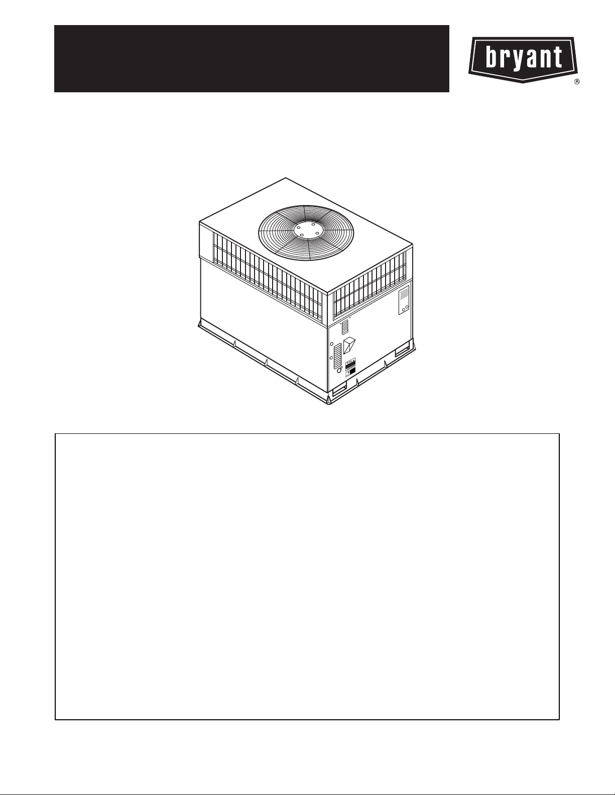
Fig. 1 -- Unit 704D
NOTE TO EQUIPMENT OWNER:
For your convenience, please record the model and serial numbers of your new equipment in the spaces
provided. This information, along with the installation data and dealer contact information, will be helpful
should your system require maintenance or service.
UNIT INFORMATION
Model # _____________________________________
Serial # ______________________________________
ACCESSORIES (List type and model #)
_____________________________________________
_____________________________________________
_____________________________________________
NOTE TO INSTALLER:
This manual must be left with the equipment owner.
INSTALLATION INFORMATION
Date Installed ________________________________
DEALERSHIP CONTACT INFORMATION
Company Name_______________________________
Address______________________________________
_____________________________________________
Phone Number _______________________________
Technician Name _____________________________
_____________________________________________
1
Page 2
SAFETY CONSIDERATIONS
Installation and servicing of this equipment can be hazardous due to
mechanical and electrical components. Only trained and qualified
personnel should install, repair, or service this equipment.
Untrained personnelcan perform basic maintenance functionssuch
as cleaning and replacing air filters. All other operations must be
performed by trained service personnel. When working on this
equipment, observe precautions in the literature, on tags, and on labels attached to or shipped with the unit and other safety precautions
that may apply.
Follow all safety codes. Installation must be in compliance with local and national building codes. Wear safety glasses, protective
clothing, and work gloves. Have fire extinguisher available. Read
these instructions thoroughly and follow all warnings or cautions
included in literature and attached to the unit.
Recognize safety information. This is the safety --alert symbol
Whenyou see thissymbolon theunit and ininstructions or manuals,
be alert to the potential for personal injury.
Understand these signal words; DANGER, WARNING,and CAUTION and NOTE. These words are used with the safety--alert symbol. DANGER identifies the most serious hazards which will result
in severe personal injury or death. WARNING signifies hazards
which could result in personal injury or death. CAUTION is used
to identify unsafe practices which may resultin minor personal injury or product and property damage. NOTE is used to highlight
suggestionswhich will result in enhanced installation, reliability, or
operation.
Note: Installer: This manual should be left with the equipment user.
!
CAUTION
FORYOURSAFETY
Failure to follow this caution may result in personal injury.
Do not store or use gasoline or other flammable vapors and
liquids in the vicinity of this or any other appliance.
!
FIRE,EXPLOSION, ELECTRICAL SHOCKHAZARD
Failure to follow this warning could result in personal injury,
death or property damage.
Do not use this unit if any part has been under water.
Immediately call a qualified service technician to inspect the
unit and to replace any part of the control system which has
been under water.
WARNING
Starting or Shutting Unit Off
To start the unit:
1. Turn on the electrical power supply to unit.
2. Select temperature and set MODE control to desired mode.
To shut unit off:
Note: If the unit is being shut down because of a malfunction, call
your dealer as soon as possible.
1. Set system MODE control to OFF.
2. Turn off the electrical power supply to unit.
OPERATING YOUR UNIT
The operation of your unit is controlled by indoor thermostat. You
simplyadjustthethermostat andit maintainsthe indoor temperature
at the level you select. Most thermostats of cooling systems have 3
controls: a temperature control selector, a FAN control, and a SYSTEM or MODE control. Refer to your thermostat owner’s manual
!
!
for more information.
To better protectyour investment and to eliminate unnecessary service calls, familiarize yourself with the following facts:
Step 1—Cooling Mode
With the SYSTEM or MODE control set to COOL, your unit will
run in cooling mode until the indoor temperature is lowered to the
level you have selected. On extremely hot days, your unit will run
for longer periods at a time and have shorter “off” periods than on
moderate days.
Step 2—Heating Mode (if installed with optional electric heat)
Your system may also be equipped with an electric heating source.
On cold days and nights, place your MODE control to HEAT and
your system will automatically turn on the supplemental heat in order to maintain the level of comfort you have selected.
MAINTENANCE AND SERVICE
This section discusses maintenance that should be performed on
your system.Most maintenance should be performed by your dealer. You, asthe owner, may wish to handle some minor maintenance
for your new unit.
Routine Maintenance
All routine maintenance should be handled by skilled, experienced
personnel. Your dealercan help you establish a standard procedure.
To assure proper functioningof the unit, flow of condenser air must
not be obstructed from reaching the unit. Clearance from the top of
the unit is 48 in. (1219 mm). Clearance of at least 36 in. (914 mm)
is required on sides except the power entry side (42 in. (1067 mm)
clearance) and the duct side (12 in. ( 305 mm) minimum clearance).
Maintenance and Care for the Equipment Owner
Before proceeding with those things you might want to maintain
yourself, please carefully consider the following:
!
WARNING
!
CUT HAZARD
Failure to follow this caution may result in personal injury,
death.
When removing access panels or performing maintenance
functions inside your unit, be aware of sharp sheet metal parts
and screws. Although special care is taken to reduce sharp
edges to a minimum, be extremely careful when handling
parts or reaching into the unit.
CAUTION
FIRE,EXPLOSION, ELECTRICAL SHOCKHAZARD
Failure to follow this warning could result in personal injury,
death or property damage.
1. TURN OFF ELECTRICAL POWER TO YOUR UNIT
BEFORE SERVICING OR PERFORMING
MAINTENANCE.
2. When removing access panels or performing maintenance
functions inside your unit, be aware of sharp sheet metal
parts and screws. Although special care is taken to reduce
sharp edges to a minimum, be extremely careful when
handling parts or reaching into the unit.
2
Page 3
Air
Filters
The air filter(s) should be checked every 3 or 4 weeks and changed
or cleaned whenever it becomes dirty. Dirty filters produce excessive stress on the blowermotor and can cause the motor to overheat
and shut down.
This unit must have air filters in place before it can be operated.
These filters can be located in one of at least two places. In many applications, the installer will provide return air filter grilles mounted
on the wall or ceiling of the conditioned structure. In the instanceof
filter grilles, the filterscan simply be removed from the grille and replaced.
The other typical application is an accessory filter rack installed inside the unit itself. The following information is given to assist in
changing filters used in these internal filter racks.
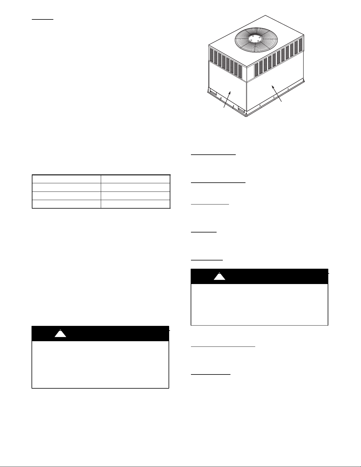
Table1 indicates the correctindoor filter size for your unit. Refer to
Fig. 2 to access filters installed in the accessory filter rack. If using
an Accessory Filter Rack refer to the Installation Instructions with
it for correct filter sizes and quantities.
Table 1—Indoor Air Filter Data
Unit Size Filter Size
704D018--- 030 20x24x1 (508x610x25 mm)
704D036 24x30x1 (610x762x25 mm)
704D042--- 060 24x36x1 (610x914x25 mm)
To replace or inspect filters in accessory filter rack (See Fig. 2):
1. Remove the filter access panel using a 5/16--in. nut driver.
2. Remove the filter(s) by pulling it out of the unit. If the filter(s)
is dirty, clean or replace with a new one.
When installing the new filter(s), note the direction of the airflow arrows on the filter frame.
If you have difficulty locating your air filter(s) or have questions
concerning proper filter maintenance, contact your dealer for instructions. When replacing filters, always use the same size and type
of filter that was supplied originally by the installer.
FILTER ACCESS
PANEL*
*For accessory filter rack.
Fig. 2 -- Accessory Filter Rack Access Panel
(Optional Louvered Panels Shown)
Drain
Fan
!
Motors
Coils
WARNING
Fans and Fan
Periodically check the condition of fan wheels and housings and
fan--motor shaft bearings. Contact your dealer for the required
annual maintenance.
Indoor and Outdoor
Cleaning of the coils should only be done by qualified service personnel. Contact your dealer for the required annual maintenance.
Condensate
The drain pan and condensate drain line should be checked and
cleaned at thesame time thecooling coils are checkedby your dealer.
Compressor
Allcompressors arefactoryshippedwith anormalchargeof the correct type of refrigeration grade oil. A compressor should rarely require additional oil.
Condenser
PERSONAL INJURY AND UNIT DAMAGE HAZARD
Failure to follow this warning could result in personal injury,
death or property damage.
Do not poke sticks, screwdrivers, or any other object into
revolving fan blades.
ACCESS PANEL
C99094
!
FIRE AND UNIT OPERATION HAZARD
Failure to follow this warning could result in personal injury,
death or property damage.
Never operate your unit without filters in place. An
accumulation of dust and lint on internal parts of your unit can
cause loss of efficiency.
WARNING
The fan must be kept free of all obstructions to ensure proper cooling. Contact your dealer for any required service.
Electrical Controls and W
Electricalcontrolsare difficult to checkwithoutproperinstrumentation. If there are any discrepancies in the operating cycle, contact
your local dealer and request service.
Refrigerant
Therefrigerantcircuitisdifficultto check forleakswithout the proper equipment. If inadequatecooling is suspected,contactyour local
dealer for service.
3
Circuit
iring
Page 4
!
WARNING
EXPLOSION AND BURN HAZARD
Failure to follow this warning could result in personal injury,
death or property damage.
System under pressure. Relieve pressure and recover all
refrigerant before system repair or final unit disposal. Use all
service ports and open all flow--control devices, including
solenoid valves.
Unit Panels
Afterperforming any maintenance or service on the unit,be sure all
panels are fastened securely in place to prevent rain from entering
unit cabinet and to prevent disruptionof the correctunit airflow pattern.
Regular Dealer Maintenance
In addition to the type of routine maintenance you might be willing
to perform, your unit should be inspected regularly by a properly
trained service technician. An inspection (preferably each year, but
at least every other year) should include the following:
1. Inspection and, if required, cleaning of the outdoor and
indoor coils.
2. Inspection and, if required, cleaning of the indoor coil drain
pan.
3. Inspection andcleaning of blower wheel housing and motor.
4. Inspection of all supply--air and return--air ducts for leaks,
obstructions, and insulation integrity. Any problems found
should be resolved at this time.
5. Inspection of the unit baseto ensurethatno cracks,gaps,etc.,
exist which may cause a hazardous condition.
6. Inspection of the unit casing for signs of deterioration.
7. Inspection of all electrical wiring and components to assure
proper connection.
8. Inspection for leaks in the refrigerant circuit. Pressure check
to determine appropriate refrigerant charge.
9. Inspection of compressor oil level by service person to
ensureproper oil level is maintained in the compressor when
it is installed and running.
10. Operational check of the unit to determine working
conditions. Repairor adjustmentshould be madeat thistime.
Your servicing dealermay offer an economical servicecontract that
covers seasonal inspections. Ask for further details.
Completeservice instructions can be found in the unit Installation,
Start--up and Service Instructions.
Warranty Certificate
Your unit has a limited warranty. Be sure to read the warranty carefully to determine the coverage for your unit.
Before you call for service...
...check for several easily--solved problems.
If insufficient heating or cooling is suspected:
( ) Check for sufficient airflow. Check the air filter for dirt. Check
for blocked return--air or supply--air grilles. Be sure they are open
and unobstructed. If these checks do not reveal the cause, call your
servicing dealer.
If your unit is not operating at all, check the following list for
easy solutions:
( ) Check to be sure that the temperature specified by your User
Interface is set below the indoortemperatureduring thecoolingseason or above the indoor temperature during heating season. Be sure
the User Interface is set to COOL or HEAT and not OFF.
( ) If your unit still fails to operate, call your servicing dealer for
troubleshooting and repairs. Specify the model and serial numbers
of your unit. (Record them in this manual in the space provided.)If
the dealer knows exactly which unit you have, he may be able to
offer suggestions over the phone, or save valuable time through
knowledgeable preparation for the service call.
In Case of Trouble
If you perform the steps aboveand unit performance is still unsatisfactory, shut off the unit and call your dealer.
Heating & Cooling Systems
TO OBTAIN INFORMATION ON PARTS: Consult your installing dealer or classified section of your local telephone directory under the
“Heating Equipment” or “Air Conditioning Contractors & Systems” heading for dealer listing by brand name.
Have available the Model No., Series Letter, & Serial No. of your equipment to ensure correct replacement part.
E2007 Bryant Heating & Cooling Systems, 7310 W. Morris St. Indpls, IN 46231
Manufacturer reserves the right to change, at any time, specifications and designs without notice and without obligations.
Printed in the U.S.A. Edition Date: 03/07
Catalog No: OM01--- 80
Replaces: New
4
 Loading...