

Bryant 704A Installation Instructions Manual
704A
SINGLE--PACKAGED AIR CONDITIONER
WITH R--22 REFRIGERANT
2--5 NOMINAL TONS (SIZES 024--060) 1 & 3 PHASE
Installation Instructions
NOTE: Read the entire instruction manual before starting the
installation.
NOTE: Installer: Make sure the Owner’s Manual and Service
Instructions are left with the unit after installation.
TABLE OF CONTENTS
Page
SAFETY CONSIDERATIONS 1........................
INTRODUCTION 2..................................
RECEIVING AND INSTALLATION 2--9.................
Check Equipment 2.................................
Identify Unit 2...................................
Inspect Shipment 2................................
Provide Unit Support 2..............................
Roof Curb 2.....................................
Slab Mount 2....................................
Ground Mount 2.................................
Provide Clearances 2................................
Field Fabricate Ductwork 2...........................
Rig and Place Unit 2................................
Inspection 2.....................................
Installation 6.....................................
Use of Rigging Bracket 6...........................
Connect Condensate Drain 7..........................
Install Duct Connections 7............................
Configuring Units for Downflow (Vertical) Discharge 7.....
Install Electrical Connections 8........................
High--Voltage Connections 9........................
Special Procedures for 208v Operation 9...............
Control Voltage Connections 9.......................
Standard Connection 9.............................
Transformer Protection 9...........................
PRE--START--UP 10..................................
START--UP 11--16....................................
Check for Refrigerant Leaks 11........................
Start--Up Adjustments 11.............................
Checking Cooling Control Operation 11...............
Checking and Adjusting Refrigerant Charge 11..........
Indoor Airflow and Airflow Adjustments 11............
Cooling Sequence of Operation 16....................
MAINTENANCE 16--18...............................
Air Filter 17.......................................
Indoor Blower and Motor 17..........................
Outdoor Coil, Indoor Coil, and Condensate Drain Pan 17....
Outdoor Fan 18....................................
Electrical Controls and Wiring 18......................
Refrigerant Circuit 18................................
Indoor Airflow 18..................................
Metering Devices–AccuRater
TROUBLESHOOTING 18.............................
START--UP CHECKLIST 18...........................
®
Piston 18................
Installation and servicing of this equipment can be hazardous due to
mechanical and electrical components. Only trained and qualified
personnel should install, repair, or service this equipment.
Untrained personnel canperform basicmaintenance functionssuch
as cleaning and replacing air filters. All other operations must be
performed by trained service personnel. When working on this
equipment, observe precautions in the literature, on tags, and on
labels attached to or shipped with the unit and other safety
precautions that may apply.
Follow all safety codes. Installation must be in compliance with
local and national building codes. Wear safety glasses, protective
clothing, and work gloves. Have fire extinguisher available. Read
these instructions thoroughly and follow all warnings or cautions
included in literature and attached to the unit.
Recognize safety information. This is the safety--alert symbol
Whenyou seethissymbolon the unit andin instructions or manuals,
be alert to the potential for personal injury. Understand these signal
words: DANGER, WARNING, and CAUTION. These words are
used with the safety--alertsymbol. DANGER identifies the most serious hazards which will result in severe personal injury or death.
WARNING signifies hazards which could resultin personalinjury
or death. CAUTION isused to identify unsafepractices which may
result in minor personal injury or product and property damage.
NOTE is used to highlight suggestions which will result in enhanced installation, reliability, or operation.
C99062
Fig. 1 -- Unit 704A
SAFETY CONSIDERATIONS
.
1
!
ELECTRICAL SHOCK HAZARD
Failure to follow this warning could result in personal injury
or death.
Before installing or servicing system, always turn off main
power to system. There may be more than one disconnect
switch. Turn off accessory heater power switch if applicable.
The 704A packaged air conditioner is fully self--contained and
designed for outdoor installation (See Fig. 1). See Fig. 2 and 3 for
unit dimensions. All unit sizes have discharge openings for both
horizontal and downflow configurations, and are factory shipped
withall downflow ductopeningscovered.The unitmay beinstalled
either on a rooftop, gound--level cement slab, or directly on the
gound if local codes permit. (See Fig. 4 for roof curb dimensions.)
704A
Step 1—Check Equipment
IDENTIFY UNIT
The unit model number and serial number are printed on the unit
informative plate. Check this information against shipping papers.
INSPECT SHIPMENT
Inspect for shipping damage while unit is still on shipping pallet. If
unit appears to be damaged or is tornloose from its anchorage, have
it examined by transportation inspectors before removal. Forward
claim papers directly to transportation company. Manufacturer is
not responsible for any damage incurred in transit. Check all items
against shipping list. Immediately notify the nearest Bryant Air
Conditioning office if any item is missing. To prevent loss or
damage, leave all parts in original packages until installation.
Step 2—Provide Unit Support
For hurricane tie downs, contact distributor for details and PE
(Professional Engineering) Certificate if required.
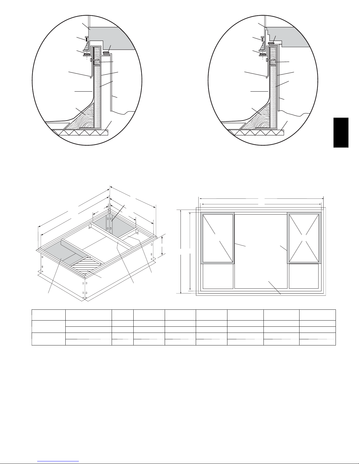
ROOF CURB
Install accessory roof curb in accordance with instructions shipped
with curb (See Fig. 4). Install insulation, cant strips, roofing, and
flashing. Ductwork must be attached to curb.
IMPORTANT: The gasketing of the unit to the roof curb is critical
for a water tight seal. Install gasketing material supplied with the
roof curb. Improperly applied gasketing also can result in air leaks
and poor unit performance.
Curb should be level to within 1/4 in. (See Fig. 6). This is necessary
for unit drain to function properly. Refer to accessory roof curb
installation instructions for additional information as required.
SLAB MOUNT
Place the unit on a solid, level concrete pad that is a minimum of 4
in. thick with 2 in. above grade. The slab should extend
approximately 2 in. beyond the casing on all 4 sides of the unit (See
Fig. 7). Do not secure the unit to the slab except when required by
local codes.
GROUND MOUNT
The unit may be installed either on a slab or placed directly on the
groundif localcodespermit.Placethe unit on level ground prepared
with gravel for condensate discharge.
Step 3—Provide Clearances
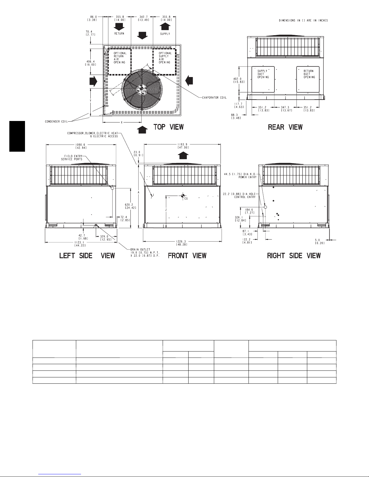
The required minimum service clearances are shown in Fig. 2 and
3. Adequate ventilation and outdoor air must be provided. The
outdoor fan draws air through the outdoor coil and discharges it
through the top fan grille. Be sure that the fan discharge does not
RECEIVING AND INSTALLATION
WARNING
INTRODUCTION
recirculate to the outdoor coil. Do not locate the unit in either a
corner or under an overhead obstruction. The minimum clearance
undera partial overhang (such as a normal house overhang) is 48 in.
above the unit top. The maximum horizontal extension of a partial
overhang must not exceed 48 in.
IMPORTANT: Do not restrictoutdoor airflow. An air restriction at
either the outdoor--air inlet or the fan discharge may be detrimental
to compressor life.
Do not place the unit where water, ice, or snow from an overhang
or roof will damage or flood the unit. Do not install the unit on
carpeting or other combustible materials. Slab--mounted units
should be at least 4 in. above the highest expected water and runoff
levels. Do not use unit if it has been under water.
Step 4—Field--Fabricate Ductwork
Secure all ducts to roof curb and building structure on vertical
discharge units. Do not connect ductwork to unit. For horizontal
applications, unit is provided with flanges on the horizontal
openings. All ductwork should be secured to the flanges. Insulate
and weatherproof all external ductwork, joints, and roof openings
with counter flashing and mastic in accordance with applicable
codes.
Ducts passing through an unconditioned space must be insulated
and covered with a vapor barrier. If a plenum return is used on a
vertical unit, the return should be ducted through the roof deck to
comply with applicable fire codes. A minimum clearance is not
requiredaround ductwork. Cabinetreturn--air staticshall not exceed
-- . 2 5 i n . w c .
Step 5—Rig and Place Unit
Rigging and handling of this equipment can be hazardous for many
reasons due to the installation location (roofs, elevated structures,
etc.).
Only trained, qualified crane operators and ground support staff
should handle and install this equipment.
When working with this equipment, observe precautions in the
literature, on tags, stickers, and labels attached to the equipment, and
any other safety precautions that might apply.
Training for operators of the lifting equipment should include, but
not be limited to, the following:
1. Application of the lifter to the load, and adjustment of the
lifts to adapt to various sizes or kinds of loads.
2. Instruction in any special operation or precaution.
3. Condition of the load as it relates to operation of the lifting
kit, such as balance, temperature, etc.
Follow all applicable safety codes. Wear safety shoes and work
gloves.
INSPECTION
Prior to initial use, and at monthly intervals, all rigging brackets and
straps should be visually inspected for any damage, evidence of
wear, structural deformation, or cracks. Particular attention should
be paid to excessive wear at hoist hooking points and load support
areas. Brackets or straps showing any kind of wear in these areas
must not be used and should be discarded.
!
ELECTRICAL SHOCK HAZARD
Failure to follow this warning could result in personal injury
or death.
Before installing or servicing system, always turn off main
power to system. There may be more than one disconnect
switch. Turn off accessory heater power switch if applicable.
Tag disconnect switch with a suitable warning label.
WARNING
2

*
704A
REQUIRED CLEARANCE TO COMBUSTIBLE MATL
(
R
efe
r t
o
M
aximu
m
O
perating
C
learance
TOP OF UNIT...................................................................................14.00 [355.6]
DUCT SIDE OF UNIT.........................................................................2.00 [50.8]
SIDE OPPOSITE DUCTS ................................................................14.00 [355.6]
BOTTOM OF UNIT.............................................................................0.50 [12.7]
NEC. REQUIRED CLEARANCES.
BETWEEN UNITS, POWER ENTRY SIDE ....................................42.00 [1066.8]
UNIT AND UNGROUNDED SURFACES, POWER ENTRY SIDE .36.00 [914.0]
UNIT AND BLOCK OR CONCRETE WALLS AND OTHER
GROUNDED SURFACES, POWER ENTRY SIDE.........................42.00 [1066.8]
UNIT
ELECTRICAL
CHARACTERISTICS
.
s
)
INCHES [mm]
INCHES [mm]
UNIT WEIGHT
lb kg X Y Z
REQUIRED CLEARANCE FOR OPERATION AND SERVICING
EVAP. COIL ACCESS SIDE............................................................36.00 [914.0]
POWER ENTRY SIDE....................................................................42.00 [1066.8]
(EXCEPT FOR NEC REQUIREMENTS)
UNIT TOP.......................................................................................48.00 [1219.2]
SIDE OPPOSITE DUCTS ..............................................................36.00 [914.0]
DUCT PANEL .................................................................................12.00 [304.8]
*MINIMUM DISTANCES: IF UNIT IS PLACED LESS THAN 304.8 [12.00] FROM
WALL SYSTEM, THEN SYSTEM PERFORMANCE MAYBE COMPROMISE.
UNIT HEIGHT
IN. [MM]
“A”
CENTER OF GRAVITY
IN. [MM]
704A024 208/230--1--60 343 156 39.02 [991] 20.0 [508] 19.3 [490] 17.6 [447]
704A030 208/230--1--60, 208/230 --3--60 366 166 41.02 [1042] 20.0 [508] 14.0 [356] 13.0 [330]
Fig. 2 -- 704A024--030 Unit Dimensions
INCHES [mm]
A05162
3
*
[
]
704A
REQUIRED CLEARANCE TO COMBUSTIBLE MATL
(
R
efe
r t
o
M
aximu
m
O
perating
C
learance
TOP OF UNIT...................................................................................14.00 [355.6]
DUCT SIDE OF UNIT.........................................................................2.00 [50.8]
SIDE OPPOSITE DUCTS ................................................................14.00 [355.6]
BOTTOM OF UNIT.............................................................................0.50 [12.7]
NEC. REQUIRED CLEARANCES.
BETWEEN UNITS, POWER ENTRY SIDE ....................................42.00 [1066.8]
UNIT AND UNGROUNDED SURFACES, POWER ENTRY SIDE .36.00 [914.0]
UNIT AND BLOCK OR CONCRETE WALLS AND OTHER
GROUNDED SURFACES, POWER ENTRY SIDE.........................42.00
UNIT
704A036 208/230--1--60, 208/230--3--60, 460 --3--60 433 196 42.98 [1092] 21.0 [533] 20.5 [520] 16.6 [422]
704A042 208/230--1--60, 208/230--3--60, 460 --3--60 460 209 46.98 [1193] 21.0 [533] 20.5 [520] 17.1 [434]
704A048 208/230--1--60, 208/230--3--60, 460 --3--60 480 218 46.98 [1193] 21.0 [533] 20.0 [508] 17.4 [442]
704A060 208/230--1--60, 208/230--3--60, 460 --3--60 492 223 46.98 [1193] 21.0 [533] 20.0 [508] 17.6 [447]
CHARACTERISTICS
.
s
)
ELECTRICAL
INCHES [mm]
INCHES [mm]
1066.8
REQUIRED CLEARANCE FOR OPERATION AND SERVICING
EVAP. COIL ACCESS SIDE............................................................36.00 [914.0]
POWER ENTRY SIDE....................................................................42.00 [1066.8]
(EXCEPT FOR NEC REQUIREMENTS)
UNIT TOP.......................................................................................48.00 [1219.2]
SIDE OPPOSITE DUCTS ..............................................................36.00 [914.0]
DUCT PANEL .................................................................................12.00 [304.8]
*MINIMUM DISTANCES: IF UNIT IS PLACED LESS THAN 304.8 [12.00] FROM
WALL SYSTEM, THEN SYSTEM PERFORMANCE MAYBE COMPROMISE.
UNIT WEIGHT
lb kg X Y Z
UNIT HEIGHT
IN. [MM]
“A”
CENTER OF GRAVITY
IN. [MM]
Fig. 3 -- 704A036--060 Unit Dimensions
INCHES [mm]
A05126
4
HVAC unit
Scre w
(NO TE A)
*Gask eting
outer flange
Flashing field
supplied
Roofing material
field supplied
Cant str ip
field supplied
base
Gask eting
inner flange*
Wood nailer*
Roof curb*
Insulation (field
supplied)
Ductwork
field supplied
HVAC unit
Scre w
(NOTE A)
*Gask eting
outer flange
Flashing field
supplied
Roofing material
field supplied
Cant str ip
field supplied
base
Gask eting
inner flange*
Ductwork
field supplied
Wood nailer*
Roof curb*
Insulation (field
supplied)
*Provided with roof curb
Roof Curb for Small Cabinet
Note A: When unit mounting scre w is used,
Return opening
UNIT SIZE
704A024-- 030
704A036-- 060
retainer bra cke t must also be used.
G
F
(B X C)
ODS CATALOG
NUMBER
CPRFCURB006A00 8 (203) 11 (279) 16--1/2 (419) 28--3/4 (730) 30 --3/8 (771) 44--5/16 (1126) 45--15/16 (1167)
CPRFCURB007A00 14 (356) 11 (279) 16--1/2 (419) 28--3/4 (730) 30 --3/8 (771) 44--5/16 (1126) 45--15/16 (1167)
CPRFCURB008A00 8 (203) 16 --3/16 (411) 17--3/8 (441) 40--1/4 (1022) 41--15/16 (1065) 44--7/16 (1129) 46--1/16 (1169)
CPRFCURB009A00 14 (356) 16--3/16 (411) 17--3/8 (441) 40--1/4 (1022) 41--15/16 (1065) 44--7/16 (1129) 46--1/16 (1169)
B Typ.
Insulated
deck pan
Roof
E
Supply opening
(B x C)
D
C Typ .
Short
Support
Long
Support
A
IN. (MM)BIN. (MM)
A
E
C
IN. (MM)
*Provided with roof curb
Roof Curb for Large Cabinet
Note A: When unit mounting scre w is used,
retainer bra cket must also be used.
G
F
R/A
D
Insulated
deck pan
D
IN. (MM)
Gask et around
duct
Gask et around
outer edge
E
IN. (MM)
F
IN. (MM)
Roof
S/A
IN. (MM)
NOTES:
1. Roof curb must be set up for unit being installed.
2. Seal strip must be applied, as required, to unit being installed.
3. Dimensions are in inches.
4. Dimension in ( ) are in millimeters.
5. Roof curb is made of 16 --gauge steel.
6. Attach ductwork to curb (flanges of duct rest on curb).
7. Insulated panels: 1-- in. thick fiberglass 1 lb. density.
8. When unit mounting screw is used (see Note A), a retainer bracket mu st be used as well. This bracket must also be used when required by code for hurricaneorseismic
conditions. This bracket is available through Micrometl.
Fig. 4 -- Roof Curb Dimensions
704A
A05308
G
5
y
A
1
2
DETAIL A
4
704A
CORNER WEIGHTS (SMALL CABINET) CORNER WEIGHTS (LARGE CABINET)
Unit 024 030 Unit 036 042 048 060
Total Weight 343 366 Total Weight 433 460 480 492
Corner Weight 1 69 74 Corner Weight 1 87 93 97 99
Corner Weight 2 53 57 Corner Weight 2 68 72 74 76
Corner Weight 3 83 88 Corner Weight 3 104 111 116 119
Corner Weight 4 138 147 Corner Weight 4 174 184 193 198
Rigging Weight 353 376 Rigging Weight 443 470 490 502
B
Fig. 6 -- Unit Leveling Tolerances
x
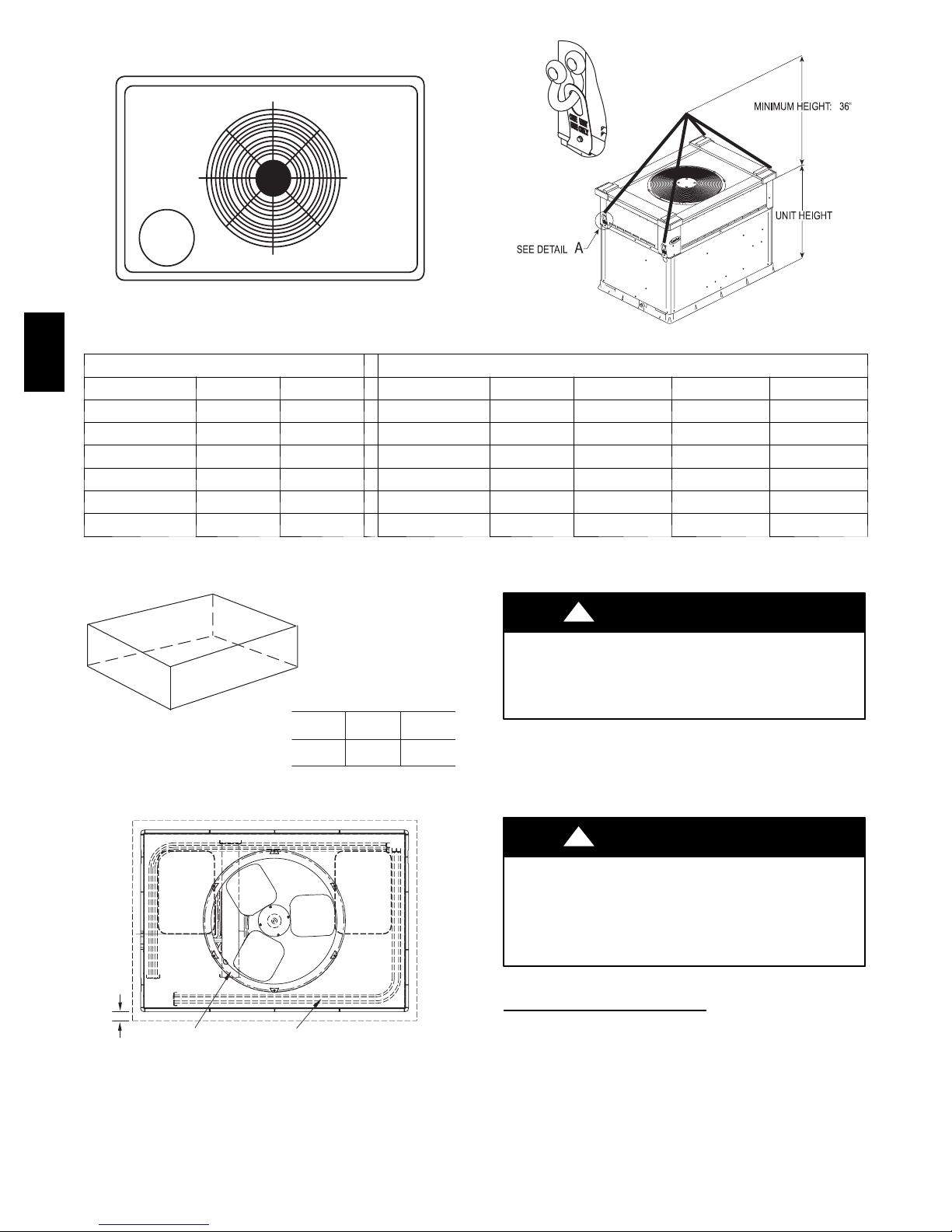
Fig. 5 -- 704A Unit Corner Weights (in Pounds) and Suggested Rigging
C
MAXIMUM ALLOWABLE
DIFFERENCE (in.)
A-B B-C A-C
1/4 1/4 1/4
3
C00071
C99065
!
UNIT FALLING HAZARD
Failure to follow this warning could result in personal injury
or death.
Never stand beneath rigged units or lift over people.
INSTALLATION
The lifting/rigging bracket is engineered and designed to be
installed only on Small Packaged Products. This bracket is to be
used to rig/lift a Small Packaged Product onto roofs or other
elevated structures.
WARNING
A05161
OPTIONAL
RETURN
AIR
OPENING
2"
EVAP. COIL COND. COIL
Fig. 7 -- Slab Mounting Detail
OPTIONAL
SUPPLY
AIR
OPENING
C99096
!
PROPERTY DAMAGE HAZARD
Failure to follow this warning could result in personal
injury/death or property damage.
Rigging brackets for one unit use only. When removing a
unit at the end of its useful life, use a new set of brackets.
USE OF RIGGING BRACKET
Field Installation of Rigging
1. If applicable, remove unit from shipping carton. Leave top
shipping skid on the unit for use as a spreaderbar to prevent
the rigging straps from damaging the unit. If the skid is not
available, use a spreader bar of sufficient length to protect the
unit from damage.
2. Remove 4 screws in unit corner posts.
6
WARNING
Bracket
 Loading...