

Bryant SINGLE PACKAGED HEAT PUMP UNITS 657A, 657A024, 657A030, 657A036, 657A042 Installation, Start-up, And Operating Instructions Manual
...
NOTE: Read the entire instruction manual before starting the
installation.
This symbol → indicates a change since the last issue.
TABLE OF CONTENTS
SAFETY CONSIDERATIONS.....................................................1
Introduction ....................................................................................2
RECEIVING AND INSTALLATION..........................................2
Check Equipment......................................................................2
IDENTIFY UNIT................................................................2
INSPECT SHIPMENT........................................................2
Provide Unit Support................................................................3
ROOF CURB & SLAB MOUNT.......................................3
Provide Clearances....................................................................4
Select and Install Ductwork .....................................................5
Rig and Place Unit....................................................................6
INSTALLATION ................................................................8
Connect Condensate Drain.......................................................9
Install Duct Connections ..........................................................9
CONFIGURING UNITS FOR DOWNFLOW (VERTI-
CAL) DISCHARGE-STANDARD UNITS (024–042)....11
CONFIGURING UNITS FOR DOWNFLOW (VERTI-
CAL) DISCHARGE-ECM UNITS (048–060).................13
Install Electrical Connection ..................................................14
HIGH-VOLTAGE & CONTROL-VOLTAGE CONNEC-
TIONS................................................................................14
SPECIAL PROCEDURES FOR 208-V OPERATION ...15
PRE-START-UP ..........................................................................15
START-UP...................................................................................17
CHECK FOR REFRIGERANT LEAKS..........................17
START UP AND MAKE ADJUSTMENTS....................18
CHECKING COOLING CONTROL OPERATION .......18
CHECKING HEATING CONTROL OPERATION........18
CHECKING AND ADJUSTING REFRIGERANT
CHARGE...........................................................................18
INDOOR AIRFLOW AND AIRFLOW ADJUST-
MENTS..............................................................................21
For 208/230v-PSC Blower Motor.....................................21
For 208/230v-ECM Blower Motor...................................21
COOLING SEQUENCE OF OPERATION.....................22
HEATING SEQUENCE OF OPERATION.....................23
MAINTENANCE.........................................................................23
AIR FILTER......................................................................24
UNIT TOP REMOVAL....................................................24
INDOOR BLOWER AND MOTOR................................24
OUTDOOR COIL, INDOOR COIL, AND CONDENSATE
DRAIN PAN......................................................................27
OUTDOOR FAN...............................................................28
ELECTRICAL CONTROLS AND WIRING ..................28
REFRIGERANT CIRCUIT...............................................29
INDOOR AIRFLOW ........................................................29
METERING DEVICE — ACUTROL DEVICE .............29
LIQUID LINE STRAINER ..............................................29
Troubleshooting............................................................................31
Start-UpChecklist........................................................................32
NOTE TO INSTALLER — Before the installation, READ THESE
INSTRUCTIONS CAREFULLY AND COMPLETELY. Also,
make sure the User’s Manual and Replacement Guide are left with
the unit after installation.
SAFETY CONSIDERATIONS
Installation and servicing of air-conditioning equipment can be
hazardous due to system pressure and electrical components. Only
trained and qualified personnel should install, repair, or service
air-conditioning equipment.
Untrained personnel can perform basic maintenance functions of
cleaning coils and filters. All other operations should be performed
by trained service personnel. When working on air-conditioning
equipment, observe precautions in the literature, tags, and labels
attached to the unit, and other safety precautions that may apply.
Follow all safety codes. Wear safety glasses and work gloves. Use
quenching cloth for unbrazing operations. Have fire extinguisher
available for all brazing operations. Consult a qualified installer or
service agency for information or assistance. The qualified installer or agency must use only factory-authorized kits or accessories when modifying this product.
WARNING: Before performing service or maintenance
operations on system, turn off power to unit. Turn off
accessory heater power switch, if applicable. Electrical
shock can cause personal injury.
Recognize safety information. This is the safety-alert symbol .
When you see this symbol in instructions or manuals, be alert to
the potential for personal injury.
Understand the signal words DANGER, WARNING, CAUTION,
and NOTE. These words are used with the safety-alert symbol.
DANGER identifies the most serious hazards which will result in
Fig. 1—Unit 657A with Optional Base Rails
C95002
Installation, Start-Up
and Operating Instructions
657A
SINGLE PACKAGED
HEAT PUMP UNITS
Cancels: II 657A.24.4 II 657A.24.5
7–03
—1—
severe personal injury or death. WARNING signifies a hazard
which could result in personal injury or death. CAUTION is used
to identify unsafe practices which would result in minor personal
injury or product and property damage. NOTE is used to highlight
suggestions which will result in enhanced installation, reliability,
or operation.
These instructions cover minimum requirements and conform to
existing national standards and safety codes. In some instances,
these instructions exceed certain local codes and ordinances,
especially those that may not have kept up with changing residential construction practices. We require these instructions as a
minimum for a safe installation.
INTRODUCTION
The 657A units (see Fig. 1) are fully self-contained, and designed
for outdoor installation. See Figs. 2–5 for unit dimensions. All
units are shipped in a horizontal-discharge configuration for
installation on a ground-level slab. All units can be converted to
down-flow discharge configurations for rooftop applications. (See
Fig. 6 for roof curb dimensions.)
RECEIVING AND INSTALLATION
I. CHECK EQUIPMENT
A. IDENTIFY UNIT
The unit model number and serial number are stamped on the unit
identification plate. Check this information against shipping papers.
B. INSPECT SHIPMENT
Inspect for shipping damage while unit is still on shipping pallet.
If unit appears to be damaged or is torn loose from its anchorage,
have it examined by transportation inspectors before removal.
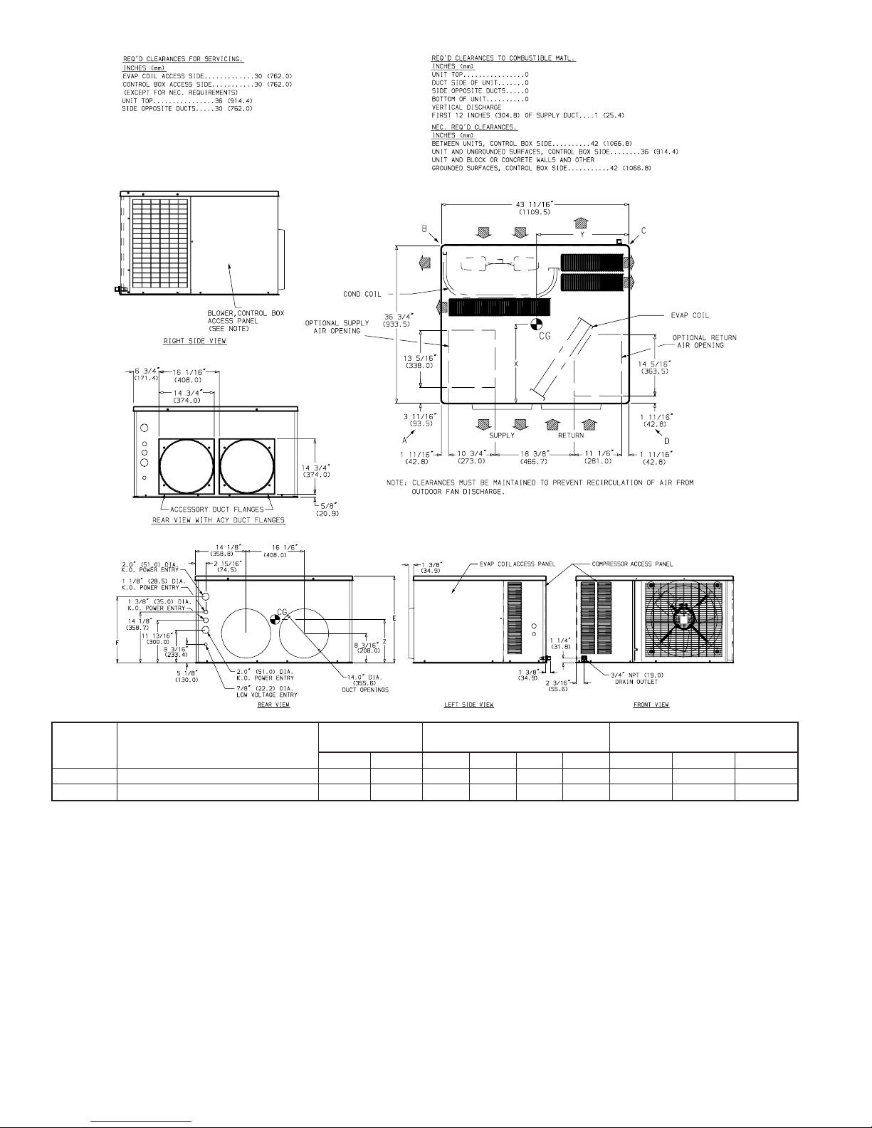
Fig. 2— 657A024-030 Unit Dimensions (without base rails)
UNIT ELECTRICAL CHARACTERISTICS
UNIT WEIGHT
CORNER WT
LB/KG
CENTER OF GRAVITY
IN/MM
lb. kg A B C D X Y Z
657A024 208/230-1-60 257 117 57/26 69/31 75/34 56/25 20.4/519 21.1/540 11.2/286
657A030 208/230-1-60 288 131 56/25 87/40 74/34 71/32 20.3/518 21.5/547 11.2/286
C95003
—2—
Forward claim papers directly to transportation company. Manufacturer is not responsible for any damage incurred in transit.
Check all items against shipping list. Immediately notify the
nearest distributor if any item is missing. To prevent loss or
damage, leave all parts in original packages until installation.
II. PROVIDE UNIT SUPPORT
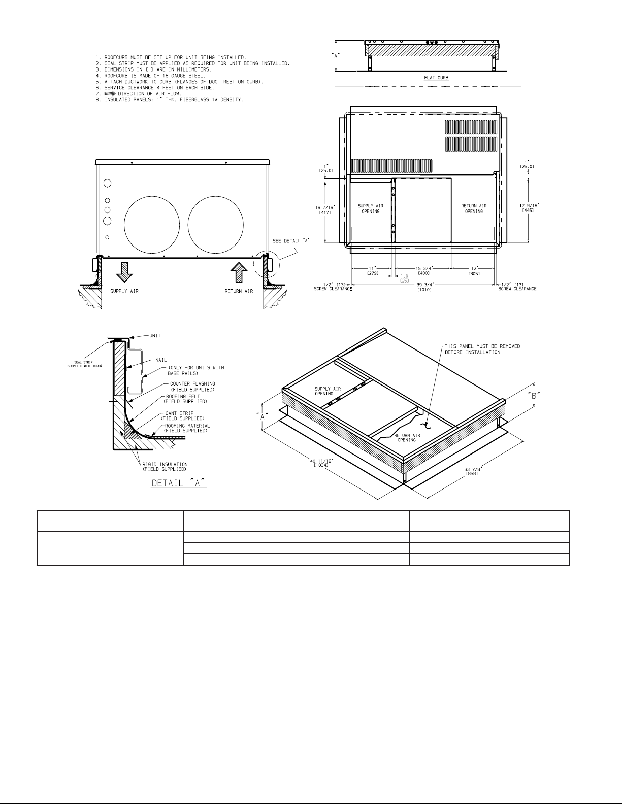
A. ROOF CURB & SLAB MOUNT
ROOF CURB - Install accessory roof curb in accordance with
instructions shipped with curb (See Fig. 6). Install insulation, cant
strips, roofing, and flashing. Ductwork must be attached to curb.
IMPORTANT: The gasketing of the unit to the roof curb is
critical for a watertight seal. Install gasketing material supplied
with the roof curb. Improperly applied gasketing also can result in
air leaks and poor unit performance.
Curb should be level to within 1/4 in (See Fig. 8). This is necessary
for unit drain to function properly. Refer to accessory roof curb
installation instructions for additional information as required.
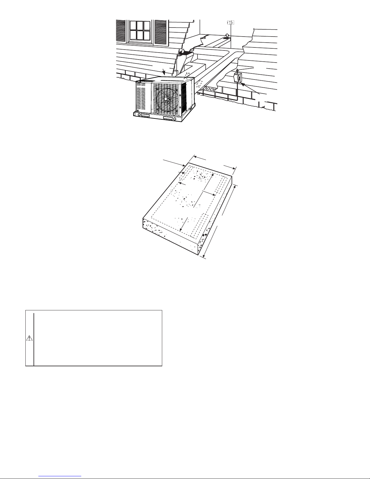
SLAB MOUNT - Place the unit on a solid, level concrete pad that
is a minimum of 4 in. thick with 2 in. above grade (See Fig. 10).
The slab should extend approximately 2 in. beyond the casing on
all 4 sides of the unit. Install a 6-in. gravel apron in front of
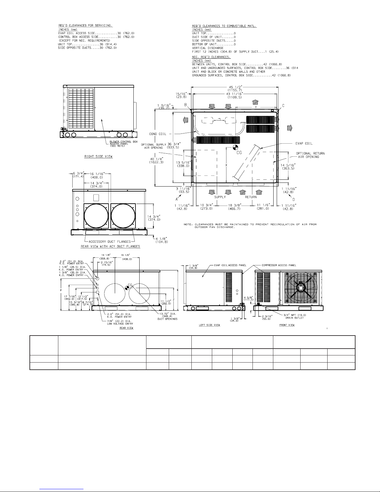
Fig. 3— 657A024-030 Unit Dimensions (with base rails)
UNIT ELECTRICAL CHARACTERISTICS
UNIT WEIGHT
CORNER WT
LB/KG
CENTER OF GRAVITY
IN/MM
lb. kg A B C D X Y Z
657A024 208/230-1-60 277 126 62/28 74/34 80/36 61/28 20.2/515 21.3/541 13.8/351
657A030 208/230-1-60 308 140 61/28 92/42 79/36 76/35 20.2/514 21.5/547 13.8/351
C95004
—3—

outdoor coil-air inlet to prevent obstruction of airflow by grass or
shrubs. Do not secure the unit to the slab except when required by
local codes.
III. PROVIDE CLEARANCES
The required minimum service clearances are shown in Fig. 2-5.
Adequate ventilation and outdoor air must be provided. The
outdoor fan pushes air through the outdoor coil and discharges it
through the louvers on the top cover, the decorative grille, and the
compressor access panel. Be sure that the fan discharge does not
recirculate to the outdoor coil. Do not locate the unit in either a
corner or under an overhead obstruction. The minimum clearance
under a partial overhang (such as a normal house overhang) is 48
in. above the unit top. The maximum horizontal extension of a
partial overhang must not exceed 48 in.
IMPORTANT: Do not restrict outdoor airflow. An air restriction
at either the outdoor-air inlet or the fan discharge may be
detrimental to compressor life.
Do not place the unit where water, ice, or snow from an overhang
or roof will damage or flood the unit. Do not install the unit on
carpeting or other combustible materials. Slab-mounted units
Fig. 4— 657A036-060 Unit Dimensions (without base rails)
UNIT ELECTRICAL CHARACTERISTICS
UNIT WEIGHT
CORNER WT
LB/KG
CENTER OF GRAVITY
IN/MM
lb. kg A B C D X Y Z
657A036 208/230-1-60 316 144 46/21 103/47 81/37 86/39 21.2/539 20.4/520 13.6/347
657A042 208/230-1-60 316 144 46/21 103/47 81/37 86/39 21.2/539 20.4/520 13.6/547
657A048 208/230-1-60 359 163 89/40 81/37 113/51 76/35 19.7/500 20.5/522 15.0/381
657A060 208/230-1-60, 373 170 92/42 85/39 116/53 80/36 19.6/499 20.6/523 15.0/381
C95005
—4—

should be at least 4 in. above the highest expected water and runoff
levels. Do not use unit if it has been under water.
IV. SELECT AND INSTALL DUCTWORK
The design and installation of the duct system must be in
accordance with the standards of the NFPA (National Fire Protection Association) for installation of nonresidence-type air conditioning and ventilating systems, NFPA90A or residence type,
NFPA90B; and/or local codes and residence-type, NFPA90B;
and/or local codes and ordinances. Select and size ductwork,
supply-air registers and return-air grilles according to ASHRAE
(American Society of Heating, Refrigeration, and Air Condition-
ing Engineers) recommendations. The unit has duct flanges on the
supply- and return-air openings on the side of the unit. See Fig. 2-5
for connection sizes and locations. When designing and installing
ductwork, consider the following:
CAUTION: When connecting ductwork to units, do not
drill deeper than 1/2–in. in shaded area shown or coil may
be damaged.
1. All units should have field-supplied filters or accessory
Fig. 5— 657A036-060 Unit Dimensions (with base rails)
UNIT ELECTRICAL CHARACTERISTICS
UNIT WEIGHT
CORNER WT
LB/KG
CENTER OF GRAVITY
IN/MM
lb. kg A B C D X Y Z
657A036 208/230-1-60 336 153 51/23 108/49 86/39 91/41 21.0/535 20.5/521 16.4/418
657A042 208/230-1-60 336 153 51/23 108/49 86/39 91/41 21.0/535 20.5/521 16.4/418
657A048 208/230-1-60 379 172 94/43 86/39 118/54 81/37 19.6/498.3 20.6/524 17.3/440
657A060 208/230-1-60, 393 179 97/44 90/41 121/55 85/39 19.5/497.3 20.6/524 17.3/440
C95006
—5—
filter rack installed in the return-air side of the unit.
Recommended sizes for filters are shown in Table 1.
2. Avoid abrupt duct size increases and reductions. Abrupt
change in duct size adversely affects air performance.
IMPORTANT: Use flexible connectors between ductwork and
unit to prevent transmission of vibration. Use suitable gaskets to
ensure weathertight and airtight seal. When electric heat is
installed, use fireproof canvas (or similar heat resistant material)
connector between ductwork and unit discharge connection. If
flexible duct is used, insert a sheet metal sleeve inside duct. Heat
resistant duct connector (or sheet metal sleeve) should extend
24-in. from electric heater element.
3. Size ductwork for cooling air quantity (cfm). The minimum
air quantity for proper electric heater operation is listed in
Table 2. Heater limit switches may trip at air quantities
below those recommended.
NOTE: A 90-degree elbow must be provided in the supply
ductwork to comply with UL (Underwriters’ Laboratories) codes
for use with electric heat.
4. Insulate and weatherproof all external ductwork. Insulate
and cover with a vapor barrier all ductwork passing through
conditioned spaces. Follow latest Sheet Metal and Air
Conditioning Contractors National Association
(SMACNA) and Air Conditioning Contractors Association
(ACCA) minimum installation standards for residential
heating and air conditioning systems.
5. Secure all ducts to building structure. Flash, weatherproof,
and vibration-isolate duct openings in wall or roof according to good construction practices.
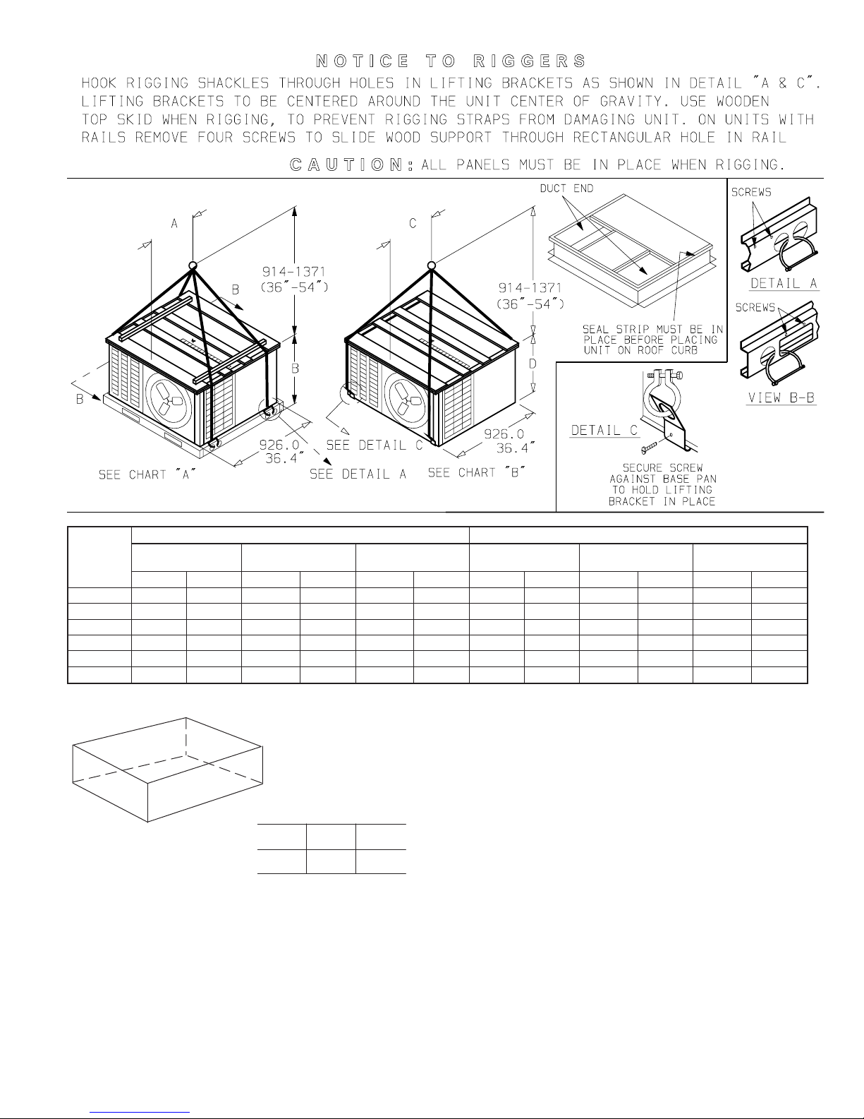
V. RIG AND PLACE UNIT
Use spreader bars or crate top when rigging the unit. The units
must be rigged for lifting as shown in Fig. 7. Use extreme caution
Fig. 6— Roof Curb Dimensions
ODS CATALOG NUMBER
A
IN. (MM)
Flat
Curb
CPRFCURB001A00 8 (203)
CPRFCURB002A00 11 (279)
CPRFCURB003A00 14 (356)
C95007
—6—
to prevent damage when moving the unit. Unit must remain in an
upright position during all rigging and moving operations. The unit
must be level for proper condensate drainage; the ground-level pad
or accessory roof curb must be level before setting the unit in
place. When a field-fabricated support is used, be sure that the
support is level and that it properly supports the unit.
UNITS WITHOUT BASE RAILS-Accessory rigging brackets are
recommended to be used for rigging. Install brackets as follows:
Fig.7—657A RiggingInstructions
UNIT
SIZE
CHART A CHART B
Max
Weight
AB
Max
Weight
CD
LB KG IN MM IN MM LB KG IN MM IN MM
024 296 134 16.1 410 32.2 817 309 140 16.0 406 28.9 733
030 327 148 16.2 411 32.2 817 340 154 16.0 407 28.9 733
036 355 161 15.4 390 38.2 969 368 167 15.2 385 34.9 885
042 355 161 15.4 390 38.2 969 368 167 15.2 385 34.9 885
048 398 180 16.9 428 38.2 969 411 186 16.8 426 34.1 867
060 412 187 16.9 429 38.2 969 425 193 16.8 427 34.1 867
C95006
Fig. 8—Unit Leveling Tolerances
C99065
A
B
C
MAXIMUM ALLOWABLE
DIFFERENCE (in.)
A-B B-C A-C
1/4 1/4 1/4
—7—
WARNING: Secure screws and paint protectors solidly
against unit base to hold lifting brackets in position.
Never use lifting brackets when the temperature is below
-10 F (-23 C). Never exceed 200 lbs per bracket of lifting
force. Never use lifting brackets for lifting other models
of air conditioning units. Lifting point should be directly
over the unit center of gravity. Failure to follow this
warning could result in personal injury or death.
1. Position brackets as close to the corners of unit as possible.
Be sure brackets are well outside of center of gravity (See
Fig. 2-5, and 7).
2. Position paint protectors and foam strips between screws
and painted surface of unit. Tighten screws until they make
contact with the paint protectors.
3. Secure device or hook of sufficient strength to hole in
bracket as shown in detail ’’C’’ of Fig. 7.
4. If wood top is available, use it for a spreader bar to prevent
straps from damaging unit. If wood top is not available, use
spreader bars of sufficient length.
UNITS WITH OPTIONAL BASE RAILS - Keep unit upright and
do not drop. Use spreader bars or top crate when rigging unit.
Rollers may be used to move unit across roof. Level unit for proper
condensate disposal. See Fig. 7 for additional information. Lifting
holes are provided in base rails as shown in Fig. 7, See Detail “A”
or “B-B”. Refer to rigging instructions on unit.
A. INSTALLATION
1. Position the lifting bracket assembly around the base of the
unit. Leave the top shipping skid on the unit to act as a
spreader bar. Be sure the strap does not twist.
2. Place each of the four (4) metal lifting brackets into the
rigging holds in the composite pan.
3. Tighten the ratchet strap unit tight. Lifting brackets should
be secure in the rigging holds.
4. Attach the clevis or hook of sufficient strength to hole in the
lifting bracket (See Fig. 7).
5. Attach safety straps directly to the field supplied rigging
straps or clevis clip. Do not attach the safety straps to the
lifting brackets.
6. Use the top of the unit as a spreader bar to prevent the
rigging straps from damaging the unit. If the wood top is not
available, use a spreader bar of sufficient length to not
damage the unit.
Fig. 9—Typical Unit Installation
C95013
INDOOR
THERMOSTAT
DISCONNECT
PER NEC
FROM
POWER
SOURCE
RETURN
AIR
TOP COVER
NOTES:
1. Extend
6-in.
gravel apron around pad.
2. Provide a3-ft service clearance
at front and rear sides of unit.
REAR SIDE OF UNIT
SIDE
OF UNIT
WITH DUCT
CONNECTIONS
1161 mm
(45 11/16”)
1110 mm
(43 11/16”)
933 mm
(36 3/4”)
SIDE OF UNIT WITH
ACCESS PANELS FOR
CONTROL BOX AND
INDOOR BLOWER HOUSING
UNIT OUTLINE
PAD
984 mm
(38 3/4”)
—8—
Fig.10—Typical Slab Layout
C95039
WARNING: Lifting point should be directly over the
center of gravity for the unit. Failure to follow this
warning could result in personal injury or death.
VI. CONNECT CONDENSATE DRAIN
NOTE: When installing condensate drain connection be sure to
comply with local codes and restrictions.
Unit disposes of condensate through a 3/4-in. NPT fitting which
exits through the compressor access panel. See Fig. 2–5 (Front
View) for location of condensate connection.
Condensate water can be drained directly onto the roof in rooftop
installations (where permitted) or onto a gravel apron in groundlevel installations. Install a field-supplied condensate trap at end of
condensate connection to ensure proper drainage. Make sure that
the outlet of the trap is at least 1-in. lower than the drain-pan
condensate connection to prevent the pan from overflowing. Prime
the trap with water. When using a gravel apron, make sure it slopes
away from the unit.
If the installation requires draining the condensate water away
from the unit, install a 2-in. trap using a 3/4-in. NPT connection
(See Fig. 18). Make sure that the outlet of the trap is at least 1-in.
lower than the unit drain-pan condensate connection to prevent the
pan from overflowing. Prime the trap with water. Connect a drain
tube using a minimum of 3/4-in. PVC, 3/4-in. CPVC, or 3/4-in.
copper pipe (all field supplied). Do not undersize the tube. Pitch
the drain tube downward at a slope of at least 1 in. for every 10 ft
of horizontal run. Be sure to check the drain tube for leaks. Prime
trap at the beginning of the cooling season start-up.
VII. INSTALL DUCT CONNECTIONS
The unit has duct flanges on the supply- and return-air openings on
the side and bottom of the unit. For downshot applications the
ductwork can be connected to the roof curb. See Fig. 2-5 for
connection sizes and locations.
IMPORTANT: Use flexible connectors between ductwork and
unit to prevent transmission of vibration. Use suitable gaskets to
ensure weathertight and airtight seal. When electric heat is
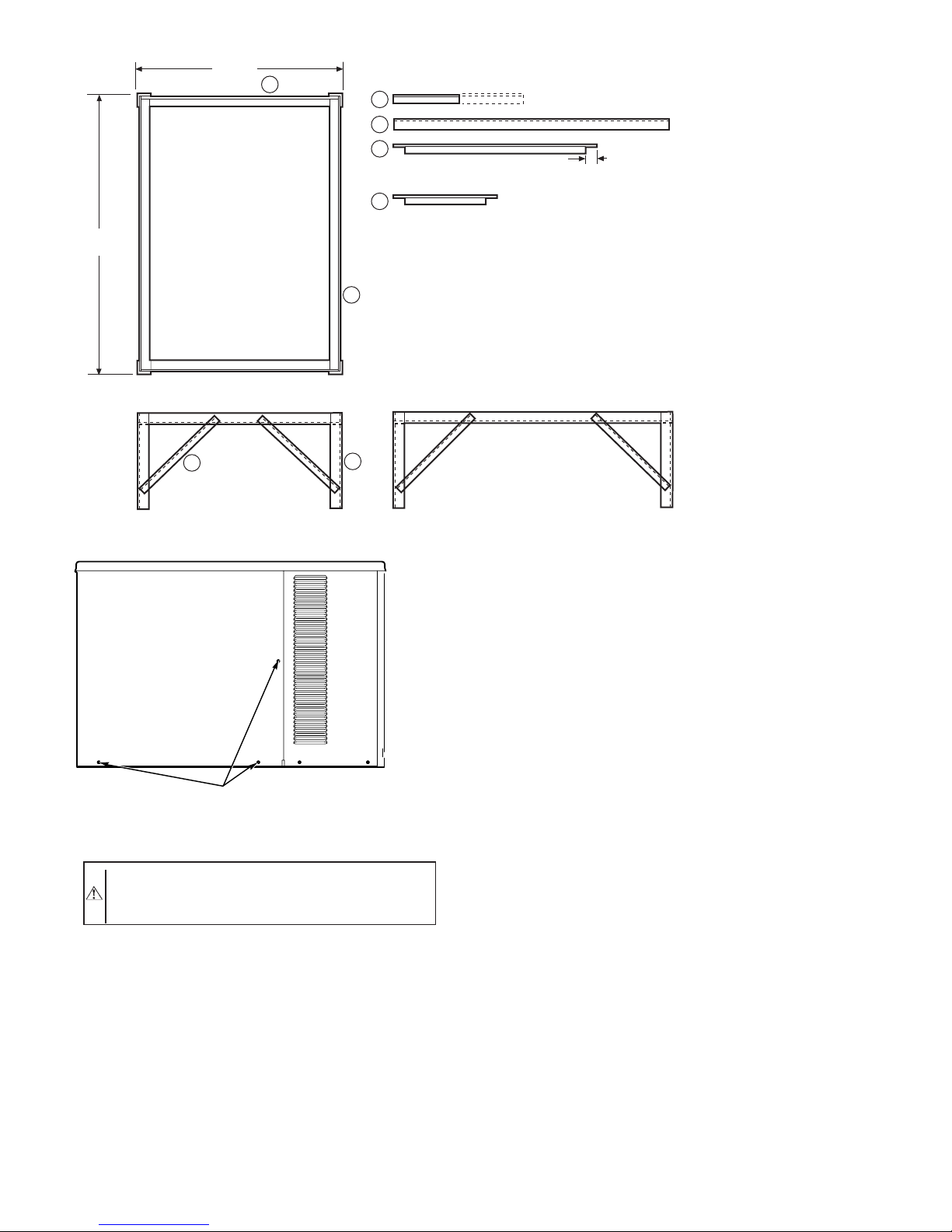
Fig. 11—Optional Heat Pump Mounting Frame
C95013
NOTES:
1. Material consistsof angle iron — 31.8 mm (1-1/4 in.) to 38 mm
(1-1/2 in.) commerical standard.
2. We ldframetogether.
3. Pa int with z inc-rich paint (rust-proof).
1
4
2
3
959 mm
(37 3/4 in.)
1
2
3
4
305 mm (12 in.) TO 610 mm (24 in.) (4) REQ.
1010 mm
(39 3/4 in.) (2) REQ.
909 mm (35 3/4 in.) (2) REQ.
38 mm (1 1/4 in.)
406 mm (16 in.) (8) REQ.
1060 mm
(41 3/4 in.)
Fig. 12—Indoor Coil Access Panel
C95014
ACCESS PANEL
(REMOVE SCREWS)
—9—
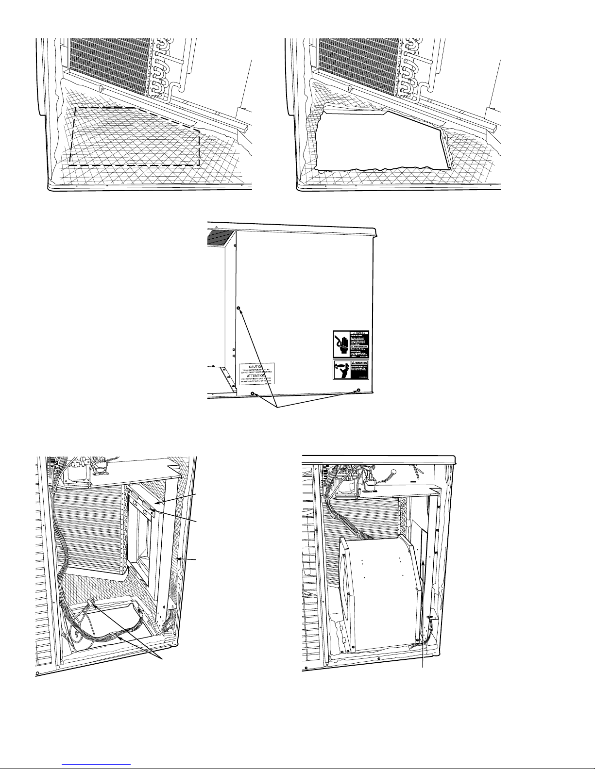
Fig. 13—Removing Insulation and Vertical Duct Cover
C95015
Fig. 14—Indoor Blower Access Panel
C950016
INDOOR BLOWER ACCESS PANEL
(REMOVE SCREWS)
Fig. 15—Converting Blower Assembly to Vertical Airflow
C950010
PLUG ASSEMBLIES
RACEWA Y
FILLER
BRACKET
BLOWER
SHELF
HORIZONTAL DUCT OPENING
—10—
 Loading...