

Bryant 650A Installation And Start-up Instructions Manual
installation and
start-up instructions
DELUXE 13 SEER
SPLIT-SYSTEM HEAT PUMP
WITH PURON® REFRIGERANT
NOTE: Read the entire instruction manual before starting the
installation.
This symbol → indicates a change since the last issue.
SAFETY CONSIDERATIONS
Improper installation, adjustment, alteration, service, maintenance,
or use can cause explosion, fire, electrical shock, or other
conditions which may cause death, personal injury, or property
damage. Consult a qualified installer, service agency, or your
distributor or branch for information or assistance. The qualified
installer or agency must use factory-authorized kits or accessories
when modifying this product. Refer to the individual instructions
packaged with the kits or accessories when installing.
Follow all safety codes. Wear safety glasses, protective clothing,
and work gloves. Use quenching cloth for brazing operations.
Have fire extinguisher available. Read these instructions thoroughly and follow all warnings or cautions included in literature
and attached to the unit. Consult local building codes and National
Electrical Code (NEC) for special requirements.
Recognize safety information. This is the safety-alert symbol
When you see this symbol on the unit and in instructions or
manuals, be alert to the potential for personal injury.
Understand the signal words DANGER, WARNING, and CAUTION. These words are used with the safety-alert symbol. DANGER identifies the most serious hazards which willresultinsevere
personal injury or death. WARNING signifies hazards which
could result in personal injury or death. CAUTION is used to
identify unsafe practices which would result in minor personal
injury or product and property damage. NOTE is used to highlight
suggestions which will result in enhanced installation, reliability,
or operation.
WARNING: Before installing, modifying, or servicing
system, main electrical disconnect switch must be in the
OFF position. There may be more than 1 disconnect
switch. Lock out and tag switch with a suitable warning
label. Electrical shock can cause personal injury or death.
CAUTION: Puron systems operate at higher pressures
than standard R-22 systems. Be certain that service
equipment is rated for Puron. Some R-22 service equipment may not be acceptable. Check with your distributor.
INSTALLATION RECOMMENDATIONS
NOTE: In some cases noise in the living area has been traced to
gas pulsations from improper installation of equipment.
1. Locate unit away from windows, patios, decks, etc. where
unit operation sound may disturb customer.
2. Ensure that vapor and liquid tube diameters are appropriate
to capacity of unit.
3. Run refrigerant tubes as directly as possible by avoiding
unnecessary turns and bends.
650A
Cancels: II 650A-24-3 II 650A-24-4
2-03
.
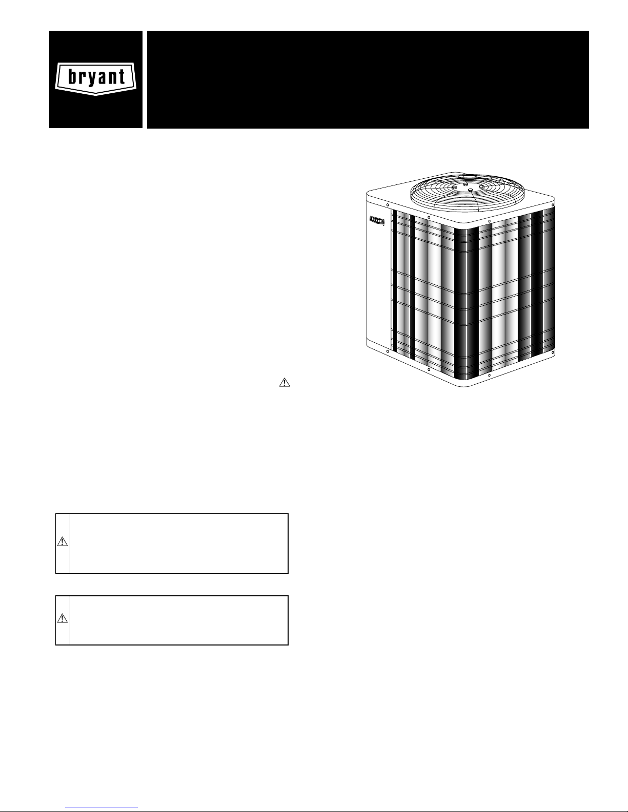
A98515
Fig. 1—Model 650A
4. Leave some slack between structure and unit to absorb
vibration.
5. When passing refrigerant tubes through the wall, seal
opening with RTV or other pliablesilicon-basedcaulk. (See
Fig. 2.)
6. Avoid direct tubing contact with water pipes, duct work,
floor joists, wall studs, floors, and walls.
7. Do not suspend refrigerant tubing from joists and studs with
a rigid wire or strap which comes in direct contact with
tubing. (See Fig. 2.)
8. Ensure that tubing insulation is pliable and completely
surrounds vapor tube.
9. When necessary, use hanger straps which are 1 in. wide and
conform to shape of tubing insulation. (See Fig. 2.)
10. Isolate hanger straps from insulation by using metal sleeves
bent to conform to shape of insulation.
When outdoor unit is connected to factory-approved indoor unit,
outdoor unit contains system refrigerant charge for operation with
indoor unit of same size when connected by 15 ft of field-supplied
or factory accessory tubing. For proper unit operation, check
refrigerant charge using charging information located on control
box cover and/or in the Check Charge section of this instruction.
IMPORTANT: Maximum liquid-line size is 3/8-in. OD for all
residential applications including long line.
IMPORTANT: Always install the factory-supplied Puron heat
pump (bi-flow) liquid-line filter drier. If replacing the filter drier,
refer to Product Data Sheet for appropriate part number. Obtain
replacement filter driers from your distributor or branch.
INSTALLATION
IMPORTANT: Specifications for this unit in residential new
construction market require the outdoor unit, indoor unit, refrigerant tubing sets, metering device, and filter drier listed in presale
—1—
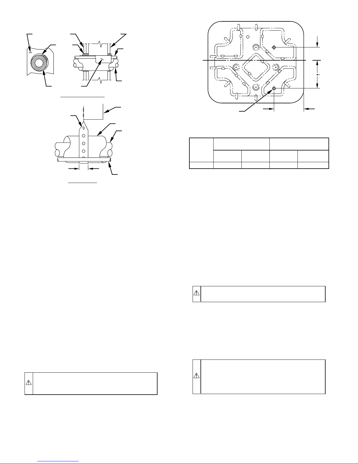
Avoid contact between tubing and structureNOTE:
OUTDOOR WALL INDOOR WALL
CAULK
INSULATION
THROUGH THE WALL
HANGER STRAP
(AROUND VAPOR
TUBE ONLY)
1″ MIN.
SUSPENSION
Fig. 2—Connecting Tubing Installation
LIQUID TUBE
VAPOR TUBE
JOIST
INSULATION
VAPOR TUBE
LIQUID TUBE
A94028
literature. There can be no deviation. Consult the Application
Guideline and Service Manual for Residential Split-System Air
Conditioners and Heat Pumps using Puron Refrigerant to obtain
required unit changes for specific applications and for R-22
retrofit.
I. CHECK EQUIPMENT AND JOB SITE
A. Unpack Unit
Move to final location. Remove carton taking care not to damage
unit.
B. Inspect Equipment
File claim with shipping company prior to installation if shipment
is damaged or incomplete. Locate unit rating plate on unit corner
panel. It contains information needed to properly install unit.
Check rating plate to be sure unit matches job specifications.
II. INSTALL ON A SOLID, LEVEL MOUNTING PAD
If conditions or local codes require the unit be attached to pad, tie
down bolts should be used and fastened through knockouts
provided in unit base pan. Refer to unit mounting pattern in Fig. 3
to determine base pan size and knockout hole location.
On rooftop applications, mount on level platform or frame. Place
unit above a load-bearing wall and isolate unit and tubing set from
structure. Arrange supporting members to adequately support unit
and minimize transmission of vibration to building. Consult local
codes governing rooftop applications.
CAUTION: Do not allow POE lubricant to come into
contact with roofing material. POE may deteriorate certain types of synthetic roofing.
A
C
L
B
3
⁄8 IN. DIA TIEDOWN
KNOCKOUTS
(2) PLACES
IN BASEPAN
DIMENSIONS (IN.)
MINIMUM MOUNTING
UNIT
SIZE
024–060 26 X 32 31 X 35 5-1/16 9-11/16
PAD DIMENSIONS
Support
Feet
Snow
Stand
Fig. 3—Mounting Unit to Pad
III. CLEARANCE REQUIREMENTS
When installing, allow sufficient space for airflow clearance,
wiring, refrigerant piping, and service. Allow 30-in. clearance to
service end of unit and 48 in. above unit. For proper airflow, a 6-in.
clearance on 1 side of unit and 12 in. on all remaining sides must
be maintained. Maintain a distance of 24 in. between units.
Position so water, snow, or ice from roof or eaves cannot fall
directly on unit.
On rooftop applications, locate unit at least 6 in. above roof
surface.
IV. OPERATING AMBIENT
The minimum outdoor operating ambient in cooling mode is 55°F,
and the maximum outdoor operating ambient in cooling mode is
125°F. The maximum outdoor operating ambient in heating mode
is 66°F.
V. ELEVATE UNIT
CAUTION: Accumulation of water and ice in base pan
may cause equipment damage.
Elevate unit per local climate and code requirements to provide
clearance above estimated snowfall level and ensure adequate
drainage of unit. Fig. 4 shows unit with accessory support feet
installed. Use accessory snow stand in areas where prolonged
freezing temperatures are encountered. Refer to Installation Instructions packaged with accessories.
VI. CHECK INDOOR EXPANSION DEVICE
CAUTION: For proper unit operation and reliability,
units must be installed with hard shutoff TXV specifically
designed to operate with Puron. Do not use an R-22 TXV.
Do not install with evaporator coils having capillary tube
metering devices or pistons.
8 3⁄16″
A97375
TIEDOWN KNOCKOUT
LOCATIONS
AB
Roof mounted units exposed to winds above 5 mph may require
wind baffles. Consult the Application Guideline and Service
Manual for Residential Split-System Air Conditioners and Heat
Pumps using Puron Refrigerant for wind baffle construction.
NOTE: Unit must be level to within ± 2° (± 3/8 in./ft) per
compressor manufacturer specifications.
For TXV kit part number and charging instructions, refer to TXV
label in outdoor unit.
A. Furnace Coils
If TXV installation is required, remove existing Check-Flo-Rater®
from indoor coil. Refer to Fig. 5 and 6 and install TXV kit
(specifically designed for Puron) as follows:
—2—
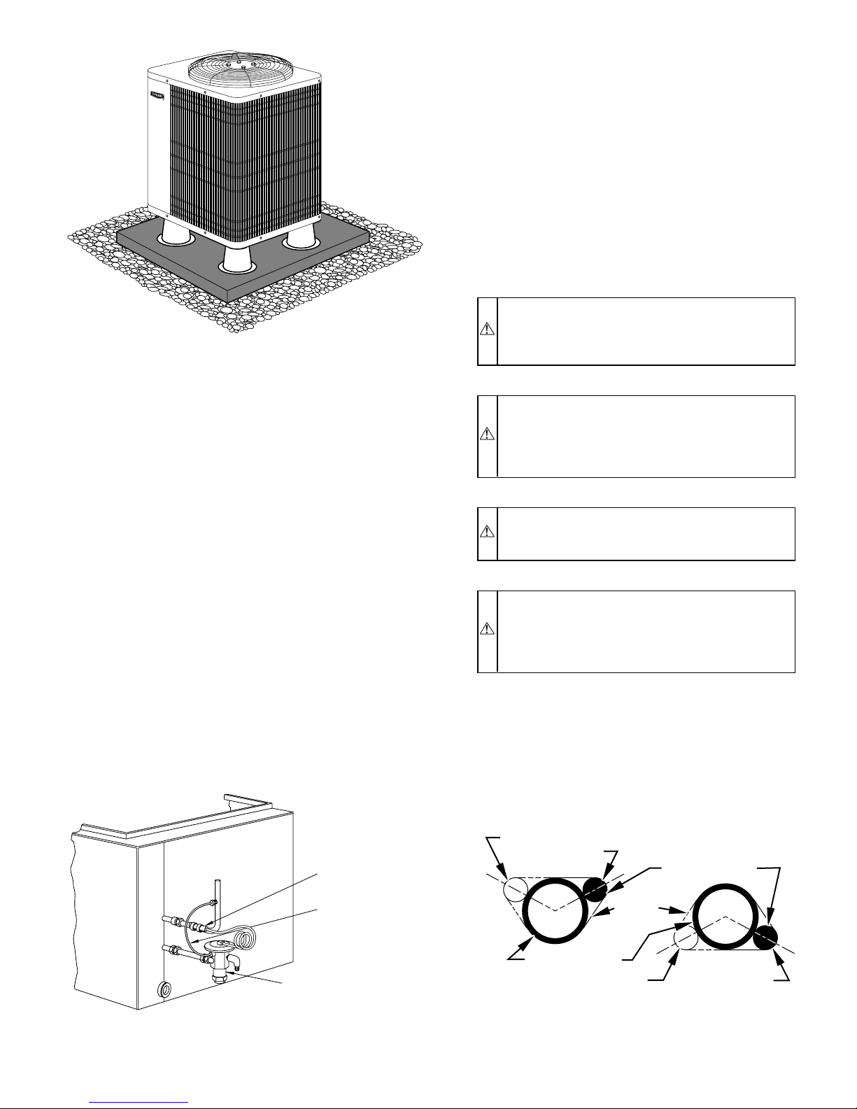
A98532
Fig. 4—Accessory Support Feet
1. Install suction tube adapter.
2. Install liquid flare-to-sweat adapter.
3. Connect external equalizer tube to fitting on suction tube
adapter.
4. Position sensing bulb on horizontal portion of suction tube
adapter. Secure using supplied hardware.
5. Insulate bulb after installation. (See Fig. 6.)
6. Leak check all connections.
B. Fan Coils
If indoor unit (fan coil) comes factory equipped with a bi-flow
hard shutoff TXV specifically designed for Puron, no TXV change
is required.
If TXV installation is required, refer to TXV kit Installation
Instructions for details on TXV installation.
VII. CHECK DEFROST THERMOSTAT
Check defrost thermostat to ensure it is properly located and
securely attached. There is a liquid header with a brass distributor
and feeder tube going into outdoor coil. At the end of 1 of the
feeder tubes, there is a 3/8-in. OD stub tube approximately 3 in.
long. (See Fig. 7.) The defrost thermostat should be located on stub
tube. Note that there is only 1 stub tube used with liquid header,
and on most units it is the bottom circuit.
VIII. IN LONG-LINE APPLICATIONS, INSTALL LIQUIDLINE SOLENOID VALVE (LSV)
For refrigerant piping arrangements with equivalent lengths
greater than 50 ft and/or when elevation difference between indoor
and outdoor unit is greater than ± 20 ft, follow all requirements of
the Long-Line Guideline section in the Application Guideline and
Service Manual for Residential Split-System Air Conditioners and
Heat Pumps Using Puron Refrigerant.
If required by Long-Line Application Guideline, install LSV kit
Part No. KHALS0401LLS specifically designed for Puron Heat
Pump. LSV should be installed within 2 ft of outdoor unit with
flow arrow pointing toward outdoor unit. Follow the Installation
Instructions included with accessory kit.
IMPORTANT: Flow arrow must point toward outdoor unit.
IX. MAKE PIPING CONNECTIONS
WARNING: Relieve pressure and recover all refrigerant
before system repair or final unit disposal to avoid
personal injury or death. Use all service ports and open all
flow-control devices, including solenoid valves.
CAUTION: Do not leave system open to atmosphere
any longer than minimum required for installation. POE
oil in compressor is extremely susceptible to moisture
absorption. Always keep ends of tubing sealed during
installation.
CAUTION: If ANY refrigerant tubing is buried, provide
a 6 in. vertical rise to the valve connections at the unit. Do
NOT bury refrigerant tubing lengths greater than 36 in.
CAUTION: To prevent damage to unit or service valves
observe the following:
• Use a brazing shield.
• Wrap service valves with wet cloth or use a heat sink
material.
Outdoor units may be connected to indoor section using accessory
tubing package or field-supplied refrigerant grade tubing of correct
size and condition. For tubing requirements beyond 50 ft, substantial capacity and performance losses can occur. Follow the
recommendations in the Application Guideline and Service
COIL
THERMOSTATIC
EXPANSION
VALVE
Fig. 5—Typical TXV Installation
SENSING
BULB
EQUALIZER
TUBE
A91277
—3—
10 O'CLOCK
2 O'CLOCK
SENSING BULB
STRAP
SUCTION TUBE
8 O'CLOCK
7
⁄
IN. OD & SMALLER
8
LARGER THAN
Fig. 6—Positioning of Sensing Bulb
4 O'CLOCK
7⁄
8
IN. OD
A81032
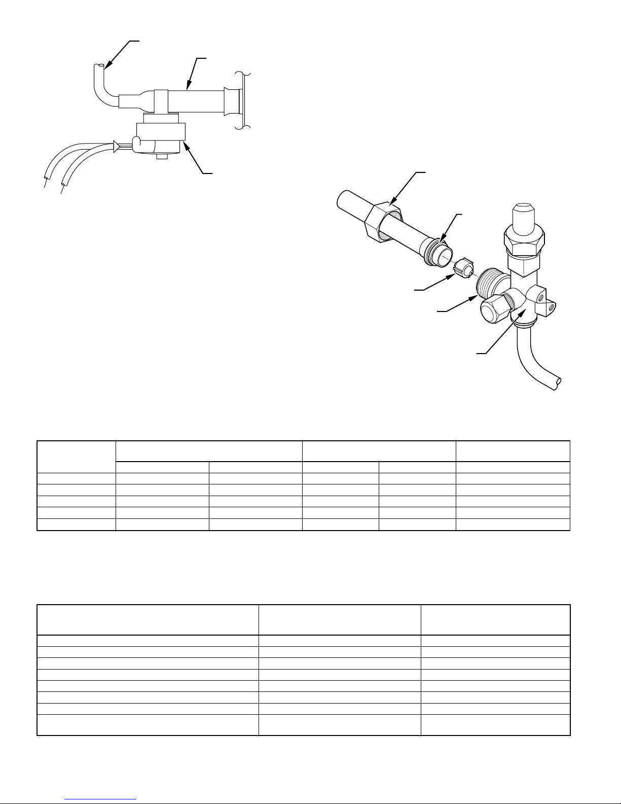
FEEDER TUBE
STUB TUBE
2. Check outdoor piston size with matching number listed on
unit rating plate.
3. Locate plastic bag taped to unit containing adapter tube.
4. Remove teflon washer from bag and install on open end of
liquid service valve. (See Fig. 8.)
5. Remove adapter tube from bag and connect threaded nut to
liquid service valve. Tighten nut finger tight and then with
wrench an additional 1/2 turn (15 ft-lb). DO NOT OVERTIGHTEN!
DEFROST
THERMOSTAT
A97517
Fig. 7—Defrost Thermostat Location
SWEAT/FLARE
ADAPTER
TEFLON
SEAL
Manual for Residential Split-System Air Conditioners and Heat
Pumps Using Puron Refrigerant to minimize losses. Refer to Table
1 for field tubing diameters. Refer to Table 2 for accessory
requirements.
Refrigerant tubes and indoor coil must be evacuated to 500
microns to minimize contamination and moisture in the system.
A. Outdoor Unit Connected to Factory-Approved
PISTON
PISTON BODY
Indoor Unit
These outdoor units are carefully evaluated and listed with specific
indoor coils for proper system performance.
IMPORTANT: Do not apply indoor coils which are not factory
LIQUID SERVICE VALVE
approved to these units.
B. Install Adapter Tube
1. Remove plastic retainer holding outdoor piston in liquid
service valve.
→
TABLE 1—REFRIGERANT CONNECTIONS AND RECOMMENDED LIQUID AND VAPOR TUBE DIAMETERS (IN.)
UNIT
SIZE
024 3/8 5/8 3/8 5/8 3/4
030 3/8 3/4 3/8 3/4 5/8, 7/8
036 3/8 3/4 3/8 3/4 5/8, 7/8
042, 048 3/8 7/8 3/8 7/8 3/4
060 3/8 7/8 3/8 1-1/8 7/8
NOTES:
1. Tube diameters are for lengths up to 50 ft. For tubing lengths greater than 50 ft horizontal or 20 ft vertical differential, consult the Application Guideline and Service Manual
for Residential Split-System Air Conditioners and Heat Pumps Using Puron Refrigerant.
2. Refrigerant tubes and indoor coils must be evacuated to 500 microns to minimize contamination and moisture in the system.
3. If required by local codes, Pressure Guard™ kit is available. See Product Data Sheet for part number.
CONNECTION DIAMETER TUBE DIAMETER
Liquid Vapor Liquid Vapor Vapor
Fig. 8—Liquid Service Valve with Sweat Adapter Tube
TUBE DIAMETER
(ALTERNATE)
A01214
ACCESSORY
Crankcase Heater Yes Yes
Evaporator Freeze Thermostat Yes No
Compressor Start Assist—Capacitor and Relay Yes Yes
Puron Low-Ambient Pressure Switch Yes No
Wind Baffle See Low-Ambient Instructions No
Support Feet Recommended No
Puron Hard Shutoff TXV Yes† Yes†
Puron Liquid-Line Solenoid Valve for Heating No
* For tubing line sets between 50 and 175 ft, refer to the Application Guideline and Service Manual for Residential Split-System Air Conditioners and Heat Pumps using Puron
Refrigerant.
† Required for all applications.
TABLE 2—ACCESSORY USAGE
REQUIRED FOR LOW-AMBIENT
APPLICATIONS
(BELOW 55°F)
—4—
REQUIRED FOR LONG-LINE
APPLICATIONS*
(OVER 50 FT)
See Long-Line
Application Guideline
 Loading...