

Bryant 619PAQ009BBMA, 619PAQ012BBMA, 619PEQ018BBMA, 619PEQ009BBMA, 619PEQ012BBMA Installation Instructions Manual
...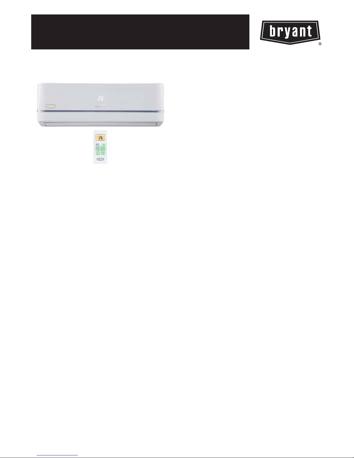
619P(A,E)Q*B
HIGH WALL DUCTLESS SPLIT SYSTEM
SIZES 09 TO 36
Installation Instructions
NOTE: Read the entire instruction manual before starting the
installation.
TABLE OF CONTENTS
PAGE
SAFETY CONSIDERATIONS 2.........................
PARTS LIS T 3.......................................
SYSTEM REQUIREMENTS 4...........................
DIMENSIONS -- INDOOR 5............................
CLEARANCES -- INDOOR 5...........................
INSTALLATION TIPS 6................................
INDOOR UNIT INSTALLATION 6.......................
ELECTRICAL DATA 7................................
CONNECTION DIAGRAMS 7..........................
INSTALL ALL POWER, INTERCONNECTING WIRING,
AND PIPING TO INDOOR UNIT 7......................
WIRELESS REMOTE CONTROL INSTALLATION 8.......
START--UP 9.........................................
TROUBLESHOOTING 10..............................
SAFETY CONSIDERATIONS
Installing, starting up, and servicing air--conditioning equipment
can be hazardous due to system pressures, electrical components,
and equipment location (roofs, elevated structures, etc.).
Only trained, qualified installers and service mechanics should
install, start--up, and service this equipment.
Untrained personnel can perform basic maintenance functions such
as cleaning coils. All other operations should be performed by
trained service personnel.
When working on the equipment, observe precautions in the
literature and on tags, stickers, and labels attached to the
equipment.
Follow all safety codes. Wear safety glasses and work gloves. Keep
quenching cloth and fire extinguisher nearby when brazing. Use
care in handling, rigging, and setting bulky equipment.
Read these instructions thoroughly and follow all warnings or
cautions included in literature and attached to the unit. Consult
local building codes and National Electrical Code (NEC) for
special requirements. Recognize safety information. This is the
!
!
safety--alert symbol
in instructions or manuals, be alert to the potential for personal
injury. Und erstand these signal words: DANGER, WARNING,
and CAUTION. These words are used with the safety--alert
symbol. DANGER identifies the most serious hazards which will
result in severe personal injury or death. WARNING signifies
hazards which could result in personal injury or death. CAUTION
is used to identify unsafe practices which may result in minor
personal injury or product and property damage. NOTE is used to
highlight suggestions which will result in enhanced installation,
reliability, or operation.
. When you see this symbol on the unit and
!
ELECTRICAL SHOCK HAZARD
Failure to follow this warning could result in personal
injury or death.
Before installing, modifying, or servicing system, main
electrical disconnect switch must be in the OFF
position. There may be more than 1 disconnect switch.
Lock out and tag switch with a suitable warning label.
!
EQUIPMENT DAMAGE HAZARD
Failure to follow this caution may result in equipment
damage or improper operation.
Do not bury more than 36 in. (914 mm) of refrigerant pipe
in the ground. If any section of pipe is buried, there must be
a 6 in. (152 mm) vertical rise to the valve connections on
the outdoor units. If more than the recommended length is
buried, refrigerant may migrate to the cooler buried section
during extended periods of system shutdown. This causes
refrigerant slugging and could possibly damage the
compressor at start--up.
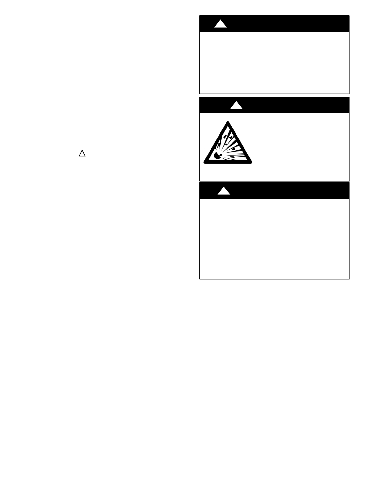
WARNING
!
WARNING
EXPLOSION HAZARD
Failure to follow this warning could
result in death, serious personal injury,
and/or property damage.
Never use air or gases containing
oxygen for leak testing or operating
refrigerant compressors. Pressurized
mixtures of air or gases containing
oxygen can lead to an explosion.
CAUTION
2

PARTS LIST
Part
No.
1 Indoor Unit 1
2 Mounting Plate 1
3 M o u n t i n g S c r e w A S T 3 . 9 x 2 5 --- C --- H 5
4 Anchor 5
5 Air Filter 1
6 Remote Control 1
7 Remote Control Holder 1
8 R e m o te C o n t r o l M o u n t i n g S cr e w B S T 2 . 0 x 1 0 --- C --- H 2
Name of Part Qty
3
4
1
2
5
6
A
U
T
O
C
O
O
D
L
R
Y
H
E
A
T
F
A
N
H
I
G
H
T
M
E
E
D
M
L
P
O
M
W
o
d
e
O
n
S
/
O
w
f
f
i
n
g
F
a
n
S
e
l
f
C
S
l
e
l
e
a
e
n
p
Fol
I
o
l
n
o
i
w
z
e
M
r
e
S
T
m
L
im
a
E
r
D
e
t
E
r
y
e
T
u
F
r
b
.
o
P
.
S
i
le
n
c
e
8
7
r Outlet
Ai
Interconnecting
Piping/wiring
Fig. 1 --- Parts List
Note:
--- If the outdoor unit is higher than the indoor unit, prevent rain from flowing into the indoor unit along the connection pipe by making a downward arc in the connection pipe before i t
enters the wall to the indoor uni t. This e nsures that rain drips from the connection pipe before it enters the wa ll.
--- Piping and the interconnecting wiring are field supplied.
--- The illustration above is only a sketch. Different models may be slightly different.
The following units are covered in these installation instructions.
Table 1—Indoor Units
Description kBTUh V --- P h --- H z Model No
9 1 1 5 --- 1 --- 6 0 619PAQ009BBMA
12 1 1 5 --- 1 --- 6 0 619PAQ012BBMA
9 208/230--- 1 --- 60 619PEQ009BBMA
High Wall
12 208/230---1 --- 60 619PEQ012BBMA
18 208/230---1 --- 60 619PEQ018BBMA
24 208/230---1 --- 60 619PEQ024BBMA
30 208/230---1 --- 60 619PEQ030BBMA
36 208/230---1 --- 60 619PEQ036BBMA
3
A150726
 Loading...