

Bryant 619ENF, 619ENQ, 619ENF018, 619ENF024, 619ENF030 Installation, Start-up And Service Instructions Manual
...Page 1
installation, start-up and
619ENF
service instructions
FAN COIL UNITS
CONTENTS
Page
SAFETY CONSIDERATIONS . . . . . . . . . . . . . . . . . . . . . . . . . 1
GENERAL . . . . . . . . . . . . . . . . . . . . . . . . . . . . . . . . . . . . . . . . 1
INSTALLATION . . . . . . . . . . . . . . . . . . . . . . . . . . . . . . . . . .1-13
I. Step 1 — Complete Pre-Installation Checks . . . . . . 1
II. Step 2 — Mount Unit . . . . . . . . . . . . . . . . . . . . . . . . . 5
III. Step 3 — Complete Refrigerant Piping
Connections . . . . . . . . . . . . . . . . . . . . . . . . . . . . . . 5
IV. Step 4 — Make Electrical Connections . . . . . . . . . . 8
START-UP . . . . . . . . . . . . . . . . . . . . . . . . . . . . . . . . . . . . . . . 13
SERVICE . . . . . . . . . . . . . . . . . . . . . . . . . . . . . . . . . . . . . . . . 14
TROUBLESHOOTING. . . . . . . . . . . . . . . . . . . . . . . . . . . .14,15
SAFETY CONSIDERATIONS
Installing and servicing air-conditioning equipment can be
hazardous due to system pressure and electrical components.
Only trained and qualified service personnel should install or
service air-conditioning equipment.
Untrained personnel can perform basic maintenance, such as
cleaning and replacing filters. All other operations should be
performed by trained service personnel. When working on air
conditioning equipment, observe safety precautions in literature, tags, and labels attached to unit.
Follow all safety codes. Wear safety glasses and work gloves.
Use quenching cloth for brazing operations. Have fire extinguisher available. Read these instructions thoroughly. Consult local building codes and the National Electrical Code
(NEC) for special installation requirements.
619ENQ
Sizes 018-036
Cancels: New II 619E-18-4
4/1/06
GENERAL
CAUTION: This system uses R-410A, which has
higher pressures than R-22 and other refrigerants. No
other refrigerant may be used in this system. All
equipment must be designed to handle R-410A refrigerant. If unsure about equipment, consult the equipment manufacturer.
These instructions cover the installation, start-up and service
of cooling only and heat pump duct-free systems.
INSTALLATION
I. STEP 1 — COMPLETE PRE-INSTALLATION CHECKS
A. Unpack Units (See Fig. 1)
Move the unit to final location. Remove unit from carton,
being careful not to damage service valves and grilles. See
Table 1A for installation materials included in shipment and
see Table 1B for field supplied materials needed to complete
the installation.
B. Inspect Shipment
File a claim with the shipping company if shipment is damaged or incomplete. Check the unit nameplate to ensure unit
matches the job requirements.
C. Consider System Requirements
Consult local building codes and NEC for special installation
requirements. Use only designated indoor units with outdoor
units. See Tables 2 and 3.
WAR NING : Before installing or servicing system,
always turn off main power to system. There may be
more than one disconnect switch. Turn off accessory
heater power if applicable. Electrical shock can cause
serious personal injury.
Fig. 1 — 619ENF,ENQ Units
Page 2
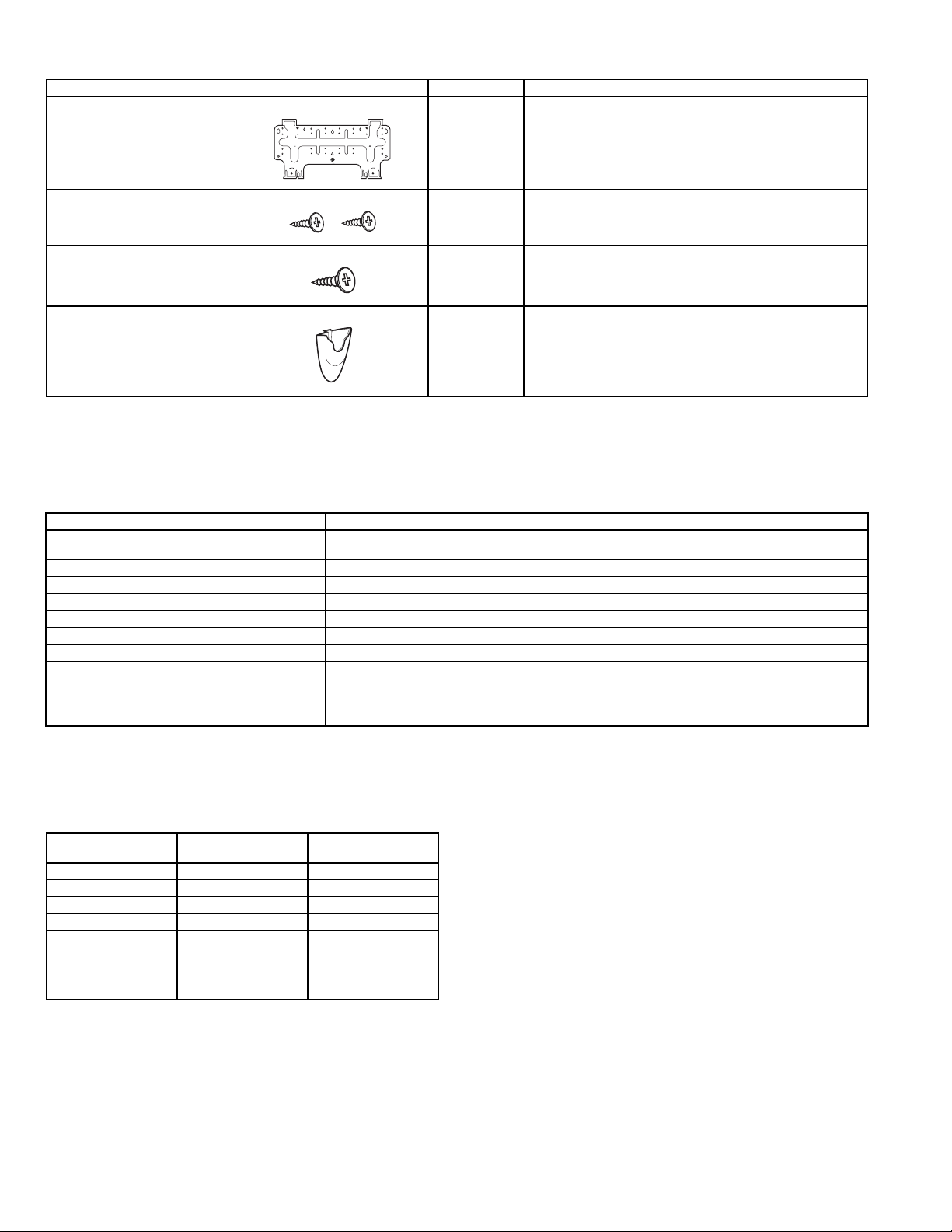
Table 1A — Installation Materials — Included In Shipment
DESCRIPTION QTY USAGE
Wall Hanging Bracket 1 For indoor unit installation.
Screws, 4xL10 2 For affixing unit and hanging bracket.
Screws, 5xL25 5/14*
Wireless Remote Control
Mounting Bracket
*619ENF01824, 619ENQ018,024: 5
619ENF,ENQ030,036: 14
Table 1B — Installation Materials — Field-Supplied
NAME SPECIFICATIONS
Connection Pipe (nominal capacity)
Wall Sleeve —
Wall Cap —
Finishing Tape PVC Film
Fastening Tape —
Pipe Insulation —
Drain Hose
Sealer Putty —
Power Supply Cable AWG 14 or higher
Electrical Connecting Cable Between
Indoor and Outdoor Unit
LEGEND
AWG — American Wire Gage
NEC — National Electrical Code
Liquid line:
Mixed Phase line:
5
/8 in. (619ENF01824 and 619ENQ018,024) 3/4 in. (619ENF,ENQ030,036)
Cable Type: AWG 14 synthetic rubber insulation with Neoprene coating, according to NEC codes.
3
/8 in. (619ENF,ENQ018-036)
5
/8 in. (619ENF01824 and 619ENQ018,024), 3/4 in. (619ENF,ENQ030,036)
For wall hanging bracket installation.
For wireless remote control mounting bracket installation.
1 For wireless remote control installation.
Table 2 — Matching Indoor Units to Outdoor Units See Fig. 2 for unit dimensions. Allow sufficient space for air-
OUTDOOR UNIT
538ENF018 Cooling Only 619ENF01824
538ENF024 Cooling Only 619ENF01824
538ENF030 Cooling Only 619ENF030
538ENF036 Cooling Only 619ENF036
538QNF018 Heat Pump 619ENQ018
538QNF024 Heat Pump 619ENQ024
538QNF030 Heat Pump 619ENQ030
538QNF036 Heat Pump 619ENQ036
COOLING ONLY OR
HEAT PUMP
INDOOR UNIT
flow clearance, wiring, refrigerant piping, and servicing
units. See Fig. 3.
Avoid mounting the unit in areas that are:
• exposed to direct sunlight
• too close to heat sources
• too close to humid conditions
• located in an area with oily ambient conditions.
—2—
Page 3
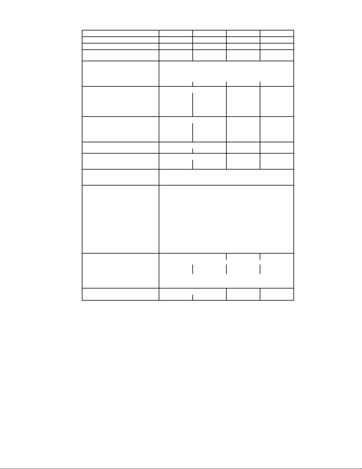
Table 3 — Indoor Unit Physical Data
SYSTEM SIZE 018 024 030 036
NOMINAL CAPACITY (Btuh) 18,000 24,000 30,000 36,000
OPERATING WEIGHT (lb) 31 31 51 51
MOISTURE REMOVAL RATE
(Pints/hr) (619ENF/ENQ)
REFRIGERANT
Type R-410A
Control Device (Cooling) Accurator Piston at Outdoor Unit
Control Device (Heating) Accurator Piston at Outdoor Unit
System Charge Required (lb)* 6.0 6.3 7.4 10.5
INDOOR FAN
Rpm/Cfm (High) 1335/645 1335/645 1030/730 1200/900
Rpm/Cfm (Med) 1120/525 1120/525 930/630 1050/750
Rpm/Cfm (Low) 1000/460 1000/460 830/530 900/600
Motor Watts 64 64 74 74
Blowers Quantity...Size 1...4.0 x 33.7 1...4.0 x 33.7 2...4.2 x 23.5 2...4.2 x 23.5
INDOOR COIL
Face Area (sq ft) 3.0 3.0 4.9 4.9
No. Rows 2222
FPI (619ENF/ENQ) 16/16 16/20 18/18 18/18
Circuits 5599
FILTERS
Quantity...Size (in.) 2...12.5 x 16.1 2...12.5 x 16.1 3...17.3 x 16.1 3...17.3 x 16.1
AIR SWEEP
Horizontal Manual Manual Automatic Automatic
Vertical Automatic Automatic Automatic Automatic
OPERATING LIMITS
Heating (Min/Max) —/81 F db
Cooling (Min/Max) 59 F wb, 70 F db/74 F wb, 90 F db
CONTROLS Integrated Microprocessor
Remote Controller Options Wireless, CRC
Diagnostics Ye s
Defrost Method Demand Defrost
Timer Mode Ye s
Warm Start Feature Ye s
Test Mode Ye s
Freeze Protection Ye s
Dehumidification Mode Ye s
Fan Mode Yes
Auto Changeover Ye s
Auto Restart Ye s
Control Voltage 24v
System Voltage 208/230
REFRIGERANT LINES
Connection Type Flare
Mixed Phase Line (in.) OD
Vapor Line (in.) OD
Max Length (ft) 200
Max Lift (Fan coil above) (ft) 60
Max Drop (Fan coil below) (ft) 60
CONDENSATE DRAIN
Size (in.)
LEGEND
CRC — Carrier Room Controller
db — dry bulb
FPI — Fins Per Inch
wb — wet bulb
*Factory charge is based on 25 ft of interconnecting line.
5.4/5.2 7.9/7.9 8.8/9.2 13.0/12.8
3
/
8
5
/
8
5
/8 OD, 7/16 ID
3
/
8
5
/
8
5
/8 OD, 7/16 ID3/4 OD, 5/9 ID3/4 OD, 5/9 ID
3
/
8
3
/
4
3
/
8
3
/
4
—3—
Page 4
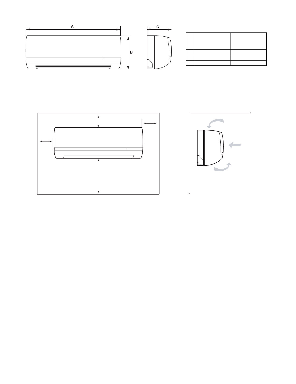
619ENF,ENQ
Fig. 2 — Unit Dimensions
619ENF01824
619ENQ018,024
DIMENSIONS
(in.)
619ENF,ENQ
030, 036
DIMENSIONS
(in.)
A 42.5 57.5
B 11.6 13.4
C 7.9 9.5
4 in.
min.
4 in.
min.
80 in.
min.
8 in.
min.
619ENF,ENQ UNITS
Fig. 3 — Unit Clearances
—4—
Page 5
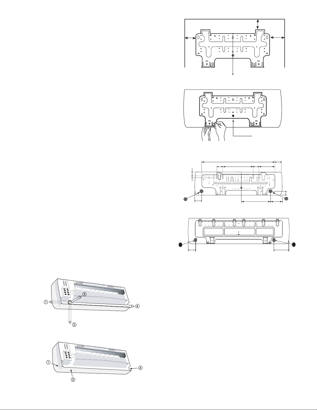
II. STEP 2 — MOUNT UNIT
Before mounting the 619ENF,ENQ unit on the wall with a
wall hanging bracket, consider how the unit will be
connected to the refrigerant piping. The indoor unit can be
connected in four ways. Refer to Fig. 4 for connection options.
When the piping is connected to points 1, 2 or 4, remove the
knockout either at the side or at the bottom of the unit.
The indoor units are mounted on the wall with a wall hanging bracket. Position the wall hanging bracket so that it is
flush with the wall. See Fig. 5 for service clearances. See
Fig. 6 for wall bracket dimensions.
Complete the following when installing the wall hanging
bracket:
1. Before installing the wall hanging bracket to the wall
remove it from the indoor unit by pushing at the indicated pressure points at the bottom of the unit.
2. Install the wall hanging bracket in a location that is
strong enough to withstand the weight of the unit.
3. Install the wall hanging bracket so that it is level.
Use a plumb line if necessary.
NOTE: Be sure that the wall hanging bracket is level. If the
wall hanging bracket is not level water will leak from the
indoor unit.
4. Fasten the wall hanging bracket to the wall with 4 or
more screw anchors through the holes near the outer
edge of the bracket.
5. Install the wall hanging bracket flush to the wall,
and ensure the bracket does not move.
6. If the unit is removed from the wall hanging bracket
after installing it on to the wall, remove it by pushing up
on the indicated marks at the bottom of the unit body.
III. STEP 3 — COMPLETE REFRIGERANT PIPING
CONNECTIONS
When running the piping for indoor units the piping can be connected as rear piping or side or bottom piping. Refer to Fig. 4.
A. Rear Piping
Route the piping behind the indoor unit so that the piping is
concealed by the unit. For rear piping installation drill a
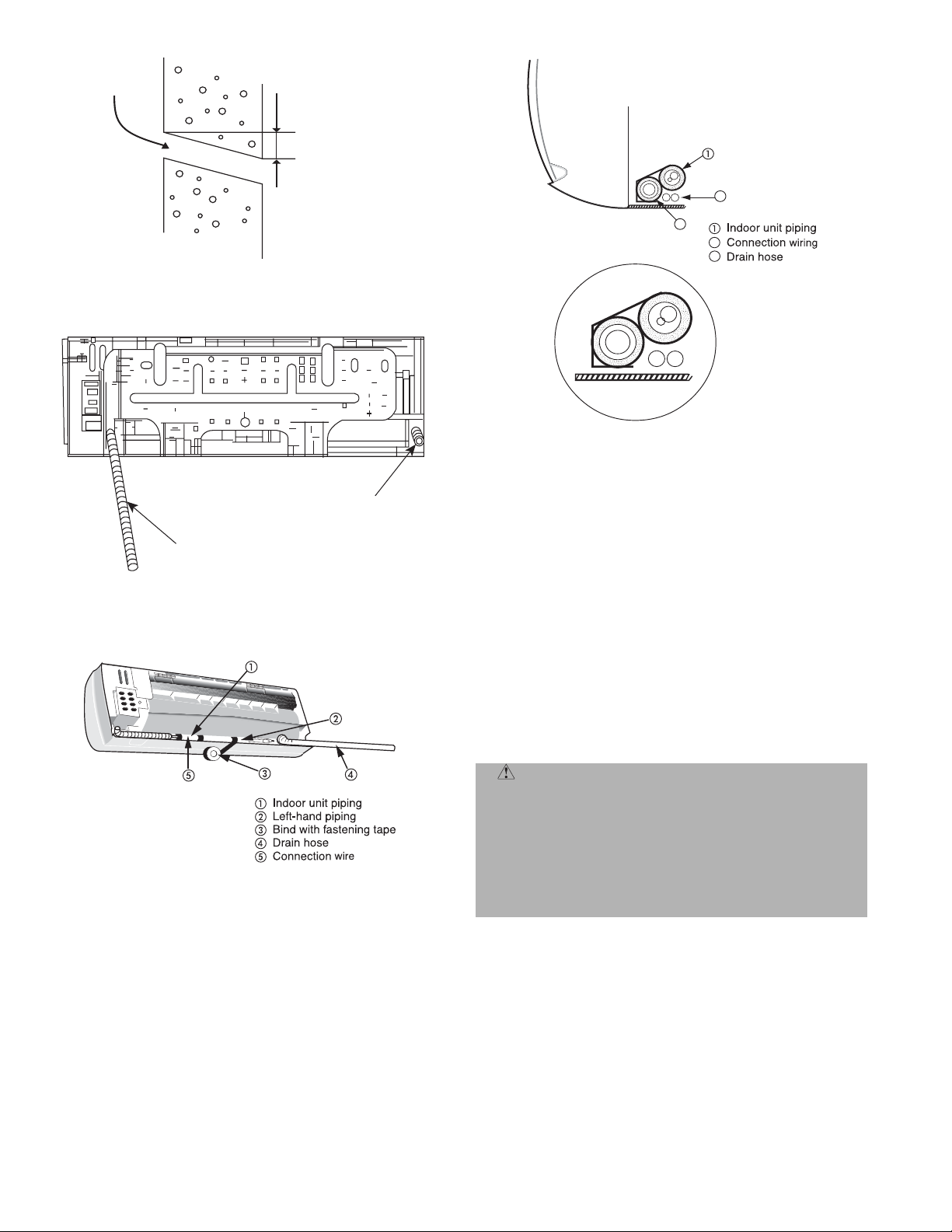
1
/2 in. diameter hole in the wall at point A or B in Fig. 6. Drill
2
the hole at a slope so that the outside end is lower (
1
/2 in.) than the inside end to ensure optimal drainage. Refer
1
/4 in. to
to Fig. 7. Pass the pipe through the hole.
Fig. 4 — Indoor Unit Piping Configurations
5 in. min.
12 in.
min.
Plumb line
Remove Screw
Fig. 5 — Installing the Wall Bracket
2.1"
1"
2"
A
A
2"
35.4"
2.8"
619ENF01824, 619ENQ018,024
619ENF, ENQ030,036
14.9"
2.8"
13.8
18 in.
min.
3.5"
7.7"
2.1"
B
5.1
"
"
B
5.1"
Fig. 6 — Wall Bracket Dimensions
B. Side or Bottom Piping
Remove the knockout in the unit and pass the piping
through the wall. The pipe should slope downward and away
from the unit to ensure optimal drainage.
C. Routing the Drain Hose and Refrigerant Piping
The drain hose and drain cap are assembled as shown in
Fig. 8 in the factory. To do right-side (1), right-bottom (2) or
right-back (3) piping in Fig. 4 draw the drain hose to rightside piping direction. (It is not always necessary to exchange
the location of drain hose and drain cap.)
1. Tie together the refrigerant piping, the drain hose,
and the electrical connection wire.
2. Route the refrigerant piping in the required direction, and bend carefully avoiding pipe deformation.
3. Bind the drain hose and the electrical connection
wire together with fastening tape.
4. The drain hose should be at the bottom. See Fig. 9
and 10.
5. For left-hand piping, fit the pipes and the wiring into
the recess at the back of the unit.
—5—
Page 6
Drill at Slope
Outdoor side
1/4 to 1/2 in. lower
Indoor side
Fig. 7 — Placement of Connection Piping
Drain Hose
Fig. 8 — Location of Drain Hose and Cap
Drain Cap
2
3
2
3
Fig. 10 — Location of Piping, Hose and Wiring
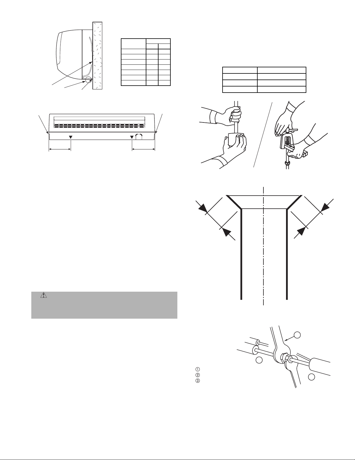
3. Fix the bottom part of the unit to the wall hanging
bracket by pushing it carefully until the two bracket
hooks fit into the marked places at the base of the
unit until it snaps into place. Refer to Fig. 11.
NOTE:
• Do not crush or kink the indoor piping. Avoid sharp bends
with a bend radius of less than 4 inches.
• Do not over bend the same part of the pipe frequently.
• Do not remove the flare nut from the indoor unit pipe
until the piping is connected.
E. Outdoor Units
Outdoor units may be connected to indoor units using fieldsupplied tubing of refrigerant grade and condition. See
Table 3 for correct line sizes. Do not use less than 10 ft of
interconnecting tubing.
Fig. 9 — Location of Piping
D. Installing the Indoor Unit Body to the Wall Hanging
Bracket
1. Pass the pipes through the wall sleeve and then hook
the indoor unit body on top of the wall hanging
bracket.
2. For left-hand piping, hang the unit on top of the wall
hanging bracket and incline the unit using a tool such
as a screwdriver set between the middle area of the
body and bottom right of the wall hanging bracket.
Connecting the pipe can be done more easily if the
unit is inclined.
CAUTION: DO NOT BURY MORE THAN 36 IN.
OF REFRIGERANT PIPE IN THE GROUND. If any
section of pipe is buried, there must be a 6-in. vertical
rise to the valve connections on the outdoor unit. If
more than the recommended length is buried, refrigerant may migrate to cooler, buried section during
extended periods of system shutdown. This causes
refrigerant slugging and could possibly damage the
compressor at start-up.
If either refrigerant tubing or indoor coil is exposed to the
atmosphere, the system must be evacuated following good
refrigeration practices.
Run refrigerant tubes as directly as possible, avoiding
unnecessary turns and bends. Suspend refrigerant tubes so
they do not damage insulation on vapor tube and do not
transmit vibration to structure. Also, when passing refrigerant tubes through a wall, seal the opening so that vibration
is not transmitted to structure. Leave some slack in refrigerant tubes between structure and outdoor unit to absorb
vibration.
—6—
Page 7
Wall
Hanging
Bracket
Hook
Hole
UNIT SIZE
619ENF01824 13.4 10.6
619ENF030 12.2 12.2
619ENF036 12.2 12.2
619ENQ018 13.4 10.6
619ENQ024 13.4 10.6
619ENQ030 12.2 12.2
619ENQ036 12.2 12.2
DIMENSION
AB
Open the mixed phase valve for 3 seconds, then quickly shut
it to check for possible leaks.
Replace caps and check for leaks using a leak detector specific for R-410A refrigerant.
After the leak test, fully open the three-way valves.
Table 4 — Tightening Torque
VALVE SIZE FLARE NUT (in.-lb)
3
/8 in. 372
5
/8 in. 487
3
/4 in. 885
Retainer
Clip
A
Retainer
Clip
B
Fig. 11 — Wall Hanging Details
F. Make Piping Sweat Connections
Remove plastic caps from liquid and suction service valves.
Use refrigerant grade tubing.
Position tube end downward and cut the tube to the
requested length. Remove the burrs with a reamer. See
Fig. 12.
NOTE: Oil in the compressor is extremely susceptible to
moisture absorption. Keep ends of tubing sealed during
installation.
Remove flare nuts from the unit connections and place them
on the tube end. Flare the tube with the flaring tool. The
flare end must not have any burrs or imperfections. The
length of the flared walls must be uniform. See Fig. 13.
Lubricate the tube end and thread of the flare fitting with
antifreeze oil. Tighten the fitting several turns, then tighten
it fully with two wrenches by applying the tightening torque
indicated in Table 4 and Fig. 14.
Fig. 12 — Removing Burrs
L
L
CAUTION: Insufficient tightening torque will
cause gas leaks. Overtightening the fittings will damage the tube flaring and cause gas leaks. Equipment
damage and personal injury may result.
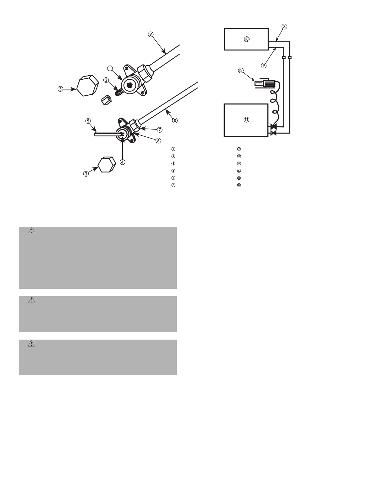
G. Air Purging And Leak Test
Only use a vacuum pump to purge air from the piping. Refer
to Fig. 15.
IMPORTANT: Do not use the system compressor as a vacuum
pump.
IMPORTANT: Do not use the unit refrigerant gas to purge
the connecting pipes.
Remove the caps from the valves. Create a vacuum with a
vacuum pump connected to the service connection of the suction shut-off valves completely shut until a 50 Pa vacuum
has been reached.
—7—
Fig. 13 — Flared Walls are Equal
3
Adjustable wrench or torque wrench
Outdoor end
Indoor end
Fig. 14 — Tightening Connections
1
2
Page 8
Three-way valve (mixed-phase)
Needle valve
Valve cap
Valve needle
Allen (hex. head) wrench
Two-way valve (liquid)
Flare nut
Liquid line (small diameter)
Mixed-phase line (large diameter)
Indoor unit
Outdoor unit
Vacuum pump
Fig. 15 — Air Purging
IV. STEP 4 — MAKE ELECTRICAL CONNECTIONS A. Power Wiring (Fig. 16-19)
Unit is factory wired for voltage shown on nameplate. Pro-
WAR NING : Unit cabinet must have an uninter-
rupted, unbroken electrical ground to minimize the
possibility of personal injury if an electrical fault
should occur. This ground may consist of electrical
wire connected to unit ground lug in control compartment, or conduit approved for electrical ground when
installed in accordance with NEC, and local electrical
codes. Failure to follow this warning could result in the
installer being liable for the personal injury of others.
vide adequate, fused disconnect switch within sight from
unit, readily accessible, but out of reach of children. Provision for locking the switch open (off) is advisable to prevent
power from being turned on while unit is being serviced. Disconnect switch, fuses, and field wiring must comply with the
NEC and local code requirements. Use copper wire only
between the disconnect switch and unit. Use minimum 60 C
wire for the field power connection.
Open the fan coil control box panel and connect the indoor
and outdoor units. Connect the wires through the terminals
CAUTION: Unit failure as a result of operation on
improper line voltage or excessive phase imbalance
as shown on the unit label diagram and in Fig. 16-19 and
Table 5. Unit must be grounded.
constitutes abuse and may cause damage to electrical
components. Such operation would invalidate any
applicable Bryant warranty.
WAR NING : Before performing service or mainte-
nance, be sure main power switch is turned OFF and
indoor blower and outdoor fan have stopped. Failure to
do so may result in electrical shock or injury from
rotating fan blades.
—8—
Page 9
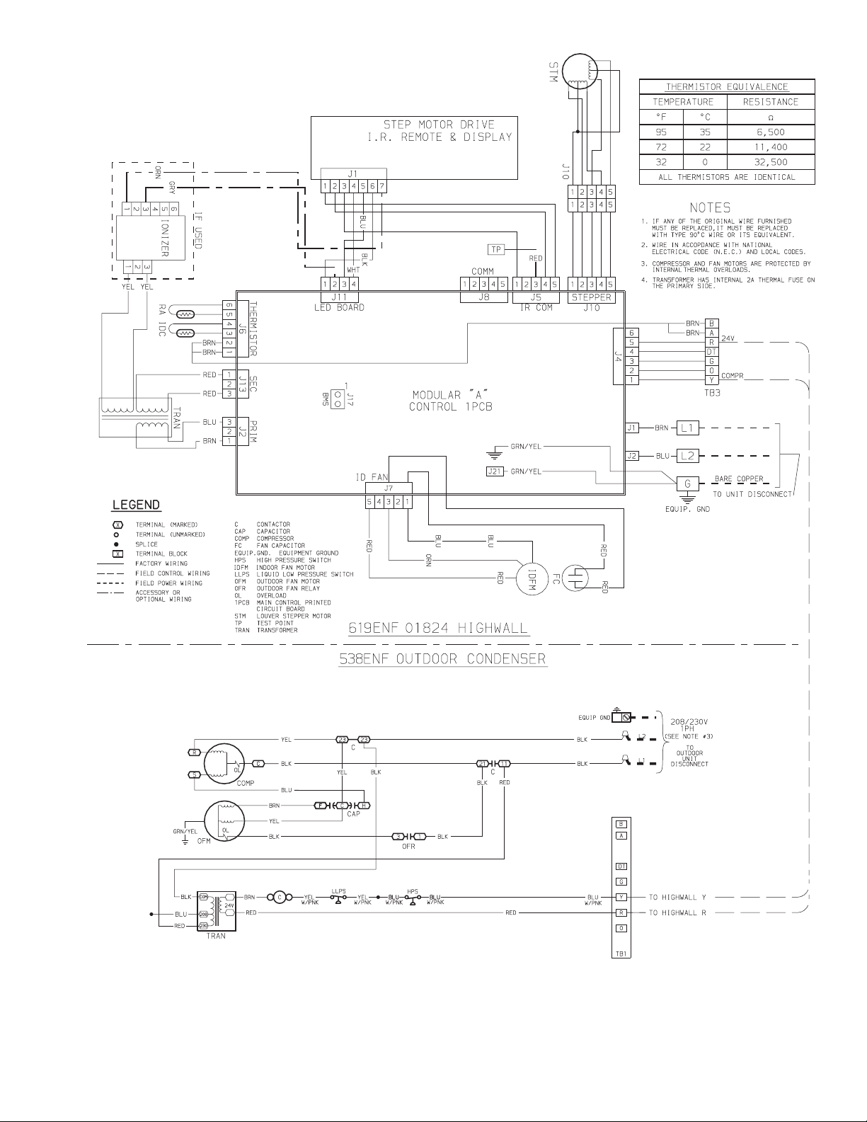
Fig. 16 — 619ENF01824 Matched with 538ENF Typical Wiring Schematic
—9—
Page 10
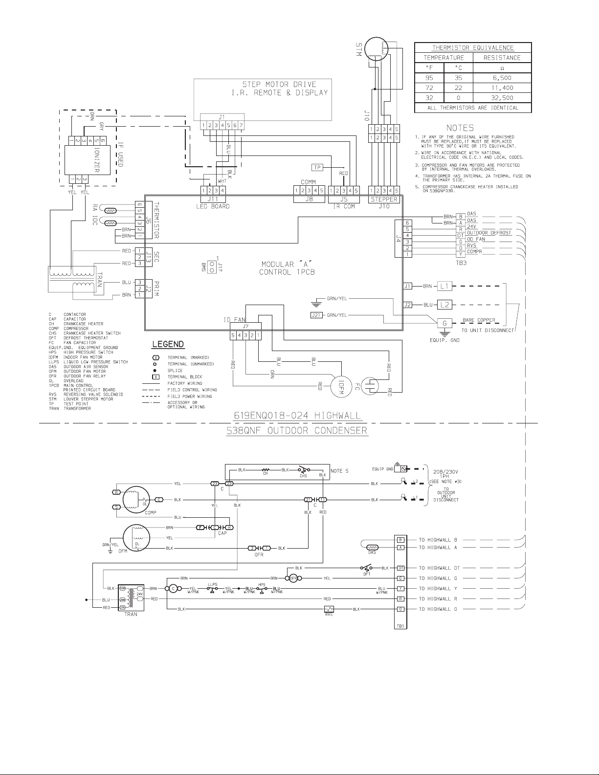
Fig. 17 — 619ENQ018,024 Matched with 538QNF Typical Wiring Schematic
—10—
Page 11
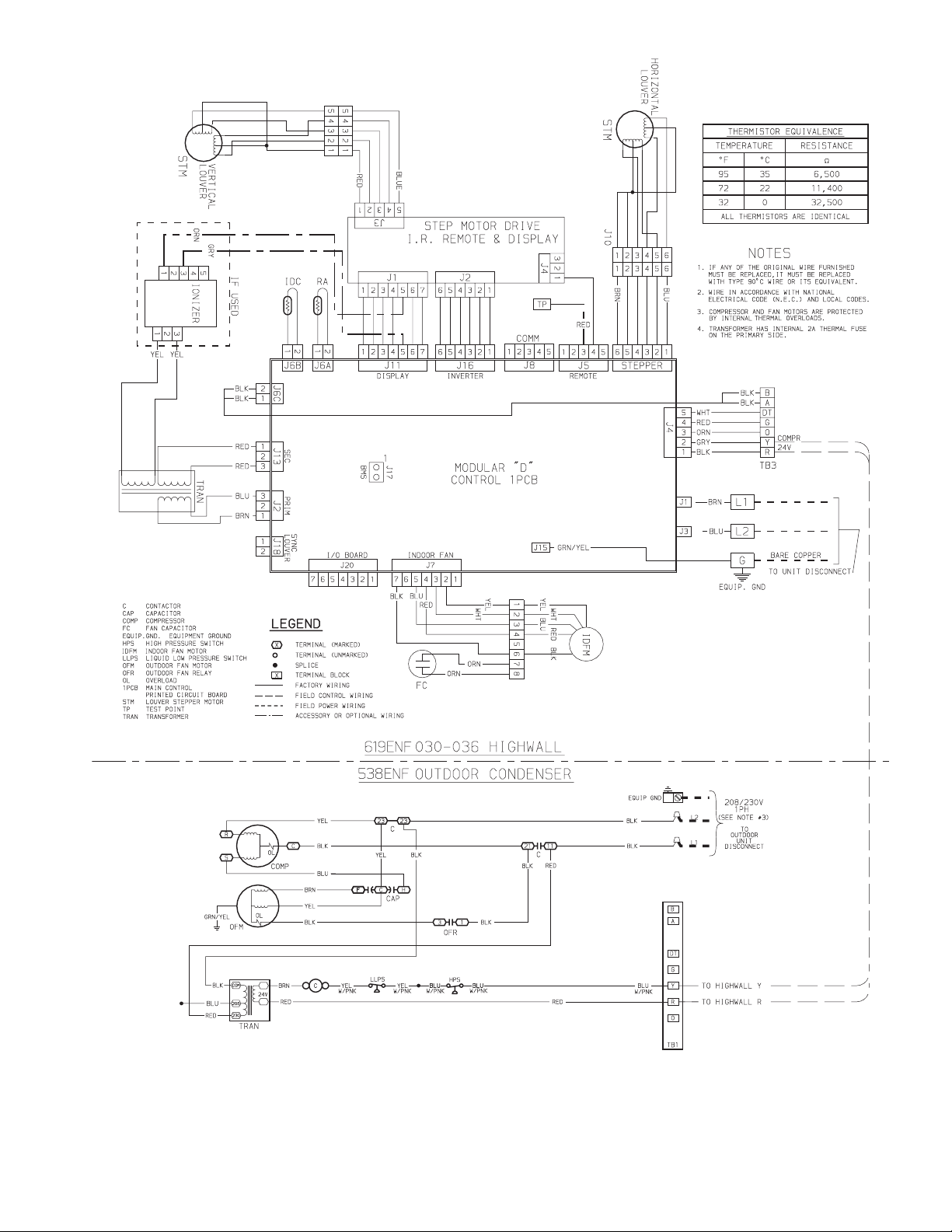
Fig. 18 — 619ENF030,036 Matched with 538ENF Typical Wiring Schematic
—11—
Page 12
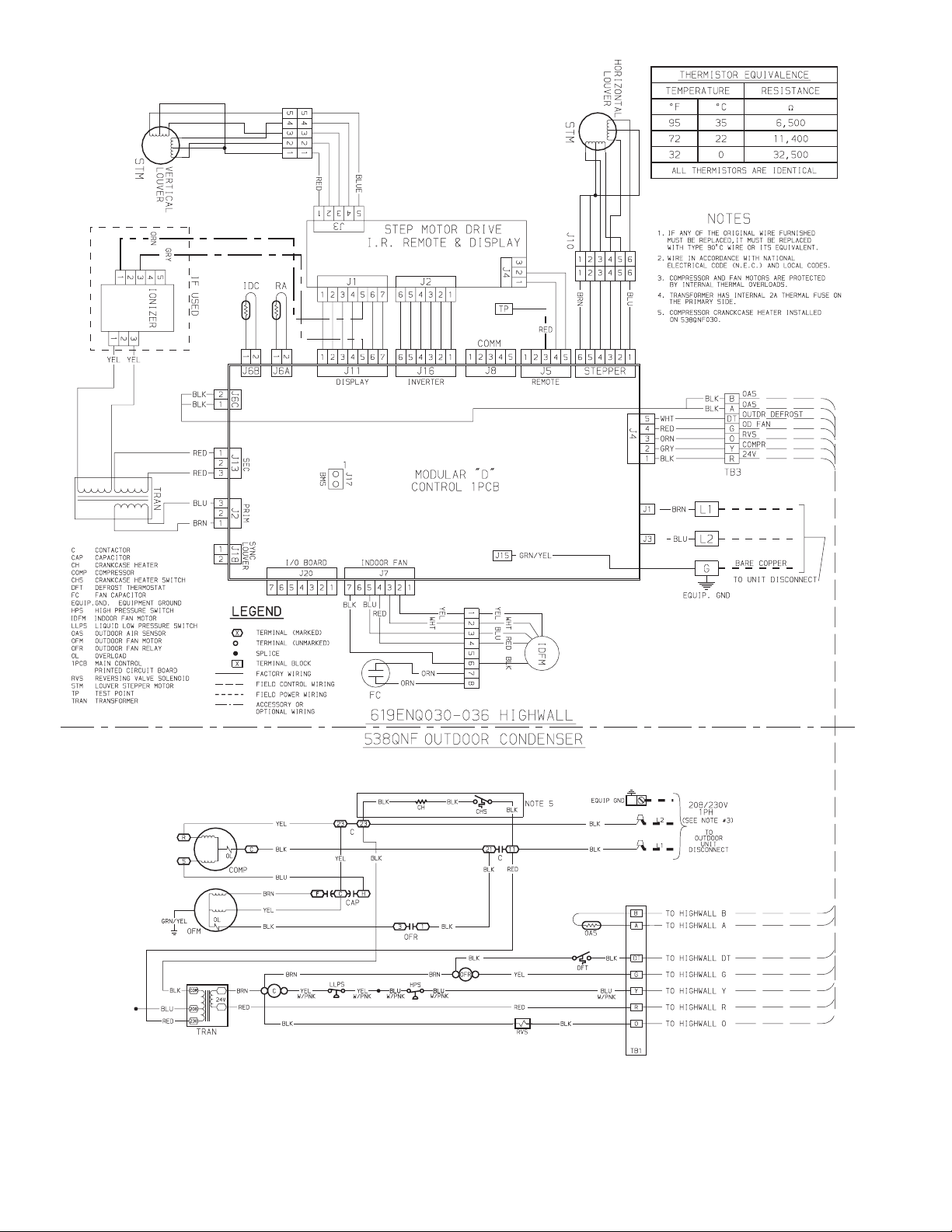
Fig. 19 — 619ENQ030,036 Matched with 538QNF Typical Wiring Schematic
—12—
Page 13
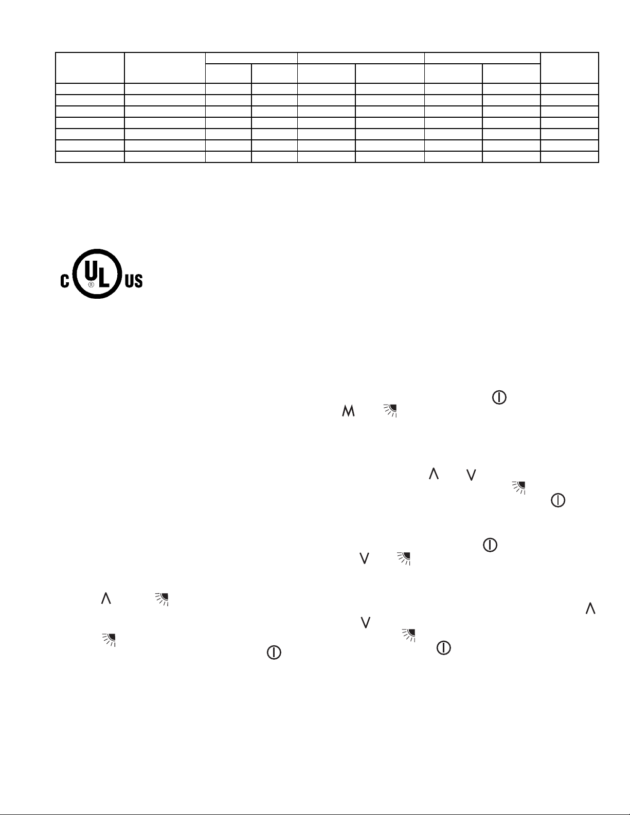
Table 5 — 619ENF,ENQ Fan Coil Electrical Data
UNIT SIZE V-PH-Hz
619ENF01824 208/230-1-60 187 253 0.38 64 0.48 15 14
619ENF030 208/230-1-60 187 253 0.38 74 0.48 15 14
619ENF036 208/230-1-60 187 253 0.44 74 0.55 15 14
619ENQ018 208/230-1-60 187 253 0.38 64 0.48 15 14
619ENQ024 208/230-1-60 187 253 0.38 64 0.48 15 14
619ENQ030 208/230-1-60 187 253 0.38 74 0.48 15 14
619ENQ036 208/230-1-60 187 253 0.44 74 0.55 15 14
LEGEND
FLA — Full Load Amps
MCA — Minimum Circuit Amps per NEC Section 430-24
MOCP — Maximum Overcurrent Protection
NEC — National Electrical Code
RLA — Rated Load Amps (Compressor)
*Permissible limits of the voltage range at which unit will operate
satisfactorily.
START-UP
I. PRELIMINARY CHECKS
1. Check that all internal wiring connections are tight
and that all barriers, covers, and panels are in place.
2. Field electrical power source must agree with unit
nameplate rating.
3. All service valves must be open.
4. Crankcase heater must be tight on compressor crankcase (if equipped).
II. LEAK TEST
Field piping and fan coil must be leak tested by pressure
method. Use R-410A at approximately 25 psig backed up
with an inert gas to a total pressure not to exceed 245 psig.
NOTE: Leak detectors should be designed to detect HFC
(hydrofluorocarbon) refrigerant.
III. EVACUATE AND DEHYDRATE
Field piping and fan coil must be evacuated and dehydrated
following good refrigeration practices.
IV. START UNIT WITH OPERATING TEST
Turn power on to the unit. Insert batteries in remote control.
Press the and the buttons on the remote control for
5 seconds. The remote control will be cleared and the time
segment will display the Src1=service test mode.
Press the button to transmit the service test signal to
the unit. After the test has completed press the button
to leave the test menu.
NOTE: When 30 seconds have elapsed and no buttons have
been pressed, the remote control will automatically exit the
test menu and resume its normal operation.
VOLTAGE RANGE* FAN POWER
Min Max FLA
Motor Power
(Watts)
NOTES:
1. In compliance with NEC requirements for multimotor and combination load equipment (refer to NEC Articles 430 and 440), the overcurrent protective device for the unit shall be fuse or equipped with a
breaker.
2. Motor RLA values are established in accordance with UL (Underwriters Laboratories) Standard 465.
MCA MOCP
V. CONFIGURING TWO INDOOR UNIT REMOTE CONTROLS
If two indoor units are being installed in the same room,
working independently, two remote controls need to be configured for proper operation.
A. Unit Configuration
Turn the unit off by pressing the . Press and hold the
and buttons of the remote control for more than
5 seconds. The display will be cleared and the time segments
will display the first configuration item (rAdr=remote
address) and the temperature segments will display the
default value of this configuration item (Ab=control of both
indoor units). Press and to change the default value
to the new value of (a) or (b). Press the button to transmit the new configuration to the unit. Press the button
to leave the configuration menu.
B. Remote Control Configuration
Turn the unit off by pressing the button. Press and hold
the and buttons for more than 5 seconds. The display will be cleared and the time segments will display the
first configuration item (CH=remote address) and the temperature segments will display the default value of this configuration item (Ab=control of both indoor units). Press
and to change the default value to the new value of (a) or
(b). Press the button to transmit the new configuration
to the unit. Press the button to leave the configuration
menu.
NOTE: When 30 seconds have elapsed and no buttons have
been pressed, the remote control will automatically exit the
test menu and resume its normal operation.
MIN WIRE
SIZE
—13—
Page 14
SERVICE
WAR NING : Before performing recommended
maintenance, be sure unit main power switch is turned
off. Failure to do so may result in electrical shock or
injury form rotating fan blade.
I. PUMPDOWN PROCEDURE
The system may be pumped down in order to make repairs
on the low side without losing complete refrigerant charge.
1. Attach pressure gage to suction service valve gage
port.
2. Frontseat the mixed phase line valve.
CAUTION: The unit coils hold only the factory-des-
ignated amount of refrigerant. Additional refrigerant
may cause units to relieve pressure through the compressor internal pressure relief valve (indicated by a
sudden rise of suction pressure) before suction pressure reaches 20 psig. If this occurs, shut off unit immediately then frontseat the suction valve and remove
and recover excess refrigerant following accepted practices. Equipment damage may result.
NOTE: Do not install a suction-line filter drier in the mixed
phase line.
III. REFRIGERANT CHARGING
WARNING: To prevent personal injury, wear
safety glasses and gloves when handling refrigerant.
Do not overcharge system — this can cause compressor
flooding.
NOTE: Do not vent or depressurize unit refrigerant to atmosphere. Remove and recover refrigerant following accepted
practices.
TROUBLESHOOTING
See Tables 6 and 7 for troubleshooting information.
I. FAULT CODE
Once a failure occurs with the indoor unit in operation, the
green LED on the indoor unit flashes at intervals of 0.5 seconds. The fault code is deduced from the number of times the
green LED flashes, blocking unit operation. Between one
flash cycle and the next one, a pause of 3 seconds elapses.
Table 6 — Green LED (Indoor Unit Fault)
3. Start unit and run until suction pressure reaches
5 psig.
4. Shut unit off and frontseat suction valve.
5. Depressurize low side of unit and recover refrigerant
following accepted practices.
II. FILTER DRIER
Whenever the filter drier is exposed to the atmosphere it
must be replaced. Only use factory specified liquid-line filter
driers with rated working pressure of at least 600 psig or
more.
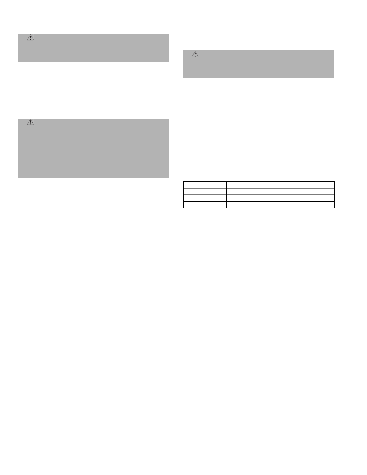
CODE DESCRIPTION
3 Room Air Sensor Fault
4 Indoor Unit Coil Sensor Fault
14 Outdoor Unit Air Sensor Fault
—14—
Page 15
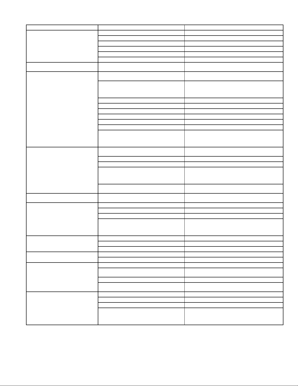
Table 7 — Troubleshooting
PROBLEM POSSIBLE CAUSE SOLUTION
Compressor and Fan of the Outdoor
Unit Will Not Start
Compressor Will Not Start, But
Outdoor Fan is Operating
Compressor Stops Due to
Overtemperature
Compressor Runs Continuously Unit selected is too small for application
Frequent Ice-Build-Up on Outdoor
Coil
Discharge Pressure Too High Outdoor coil dirty or obstructed Clean or remove obstructions.
Discharge Pressure Too Low Indoor temperature setting too high or too low Check temperature setting.
Suction Pressure Too High Indoor temperature setting too high or too low Check temperature setting.
Suction Pressure Too Low Indoor temperature setting too high or too low Check temperature setting.
Outdoor Fan Cycling Due to
Over-Temperature Protection
Unit not energized Check the main power connection.
Main switch is set to OFF Check and put it to ON position.
Main switch fuses are blown Replace fuses.
Compressor cycling protection is on Wait for 3 minutes.
Main power voltage is too low Check and set to the correct voltage.
Electrical connections are too loose or are wrong Check and tighten or correct connections.
Electrical connections of compressor are loose
or wrong
Compressor burnt out; seized or protection
device on
Wrong refrigerant charge in unit (excessive or
low) or air or other noncondensable gasses in
the circuit
Main voltage is too high or too low Check voltage setting and adjust if necessary.
Condenser coil obstructed Remove obstruction.
Outdoor fan off Check cause and resume operation or repair.
Wrong indoor unit thermistors Replace thermistors.
Refrigerant circuit clogged Check and remove obstructions.
Reversing valve faulty on heat pump models Replace reversing valve.
Expansion device clogged or covered with ice Drain refrigerant, evacuate and recharge.
requirements
Indoor temperature setting too low or too high Check temperature setting.
Outdoor unit fan faulty Replace outdoor fan.
Air or other noncondensable gasses in the
circuit
Obstructions at air intake or dirty indoor unit
filters
Outdoor fan is stopped Check cause and repair.
Condenser fan faulty Replace condenser fan.
Indoor temperature setting too low or too high Check temperature setting.
Air or other noncondensable gasses in the
circuit
Outdoor coil dirty or obstructed Clean or remove obstructions.
Indoor unit air filter dirty Clean filter.
Reversing valve faulty or internal leak Replace reversing valve.
Evaporator coil covered with ice Air circulation on the evaporator not sufficient; check
Expansion device or suction line clogged Check and repair.
Outdoor fan does not stop during defrost
periods
Electrical connection loose Check connections.
Fan motor burn out Replace.
Fan bearing seized Check and repair.
Expansion device clogged or covered with ice Drain refrigerant, evacuate and replace.
Check and tighten or repair compressor.
Check for the cause and replace compressor if
necessary.
Drain refrigerant, evacuate and recharge.
CAUTION: Do not vent refrigerant to the atmosphere;
use refrigerant recovery equipment.
CAUTION: Do not vent refrigerant to the atmosphere;
use refrigerant recovery equipment.
Contact a qualified service technician for a system
evaluation.
Drain refrigerant, evacuate and recharge.
CAUTION: Do not vent refrigerant to the atmosphere;
use refrigerant recovery equipment.
Remove obstruction and/or clean filter.
Drain refrigerant, evacuate and recharge.
CAUTION: Do not vent refrigerant to the atmosphere;
use refrigerant recovery equipment.
and repair.
Check electrical parts.
CAUTION: Do not vent refrigerant to the atmosphere;
use refrigerant recovery equipment.
—15—
Page 16

Copyright 2006 Bryant Heating & Cooling Systems Printed in U.S.A. CATALOG NO. 02-619E0001-SI
 Loading...