

Bryant 619ENF, 619ENQ, 619ENF018, 619ENF024, 619ENF030 Installation, Start-up And Service Instructions Manual
...
installation, start-up and
619ENF
service instructions
FAN COIL UNITS
CONTENTS
Page
SAFETY CONSIDERATIONS . . . . . . . . . . . . . . . . . . . . . . . . . 1
GENERAL . . . . . . . . . . . . . . . . . . . . . . . . . . . . . . . . . . . . . . . . 1
INSTALLATION . . . . . . . . . . . . . . . . . . . . . . . . . . . . . . . . . .1-13
I. Step 1 — Complete Pre-Installation Checks . . . . . . 1
II. Step 2 — Mount Unit . . . . . . . . . . . . . . . . . . . . . . . . . 5
III. Step 3 — Complete Refrigerant Piping
Connections . . . . . . . . . . . . . . . . . . . . . . . . . . . . . . 5
IV. Step 4 — Make Electrical Connections . . . . . . . . . . 8
START-UP . . . . . . . . . . . . . . . . . . . . . . . . . . . . . . . . . . . . . . . 13
SERVICE . . . . . . . . . . . . . . . . . . . . . . . . . . . . . . . . . . . . . . . . 14
TROUBLESHOOTING. . . . . . . . . . . . . . . . . . . . . . . . . . . .14,15
SAFETY CONSIDERATIONS
Installing and servicing air-conditioning equipment can be
hazardous due to system pressure and electrical components.
Only trained and qualified service personnel should install or
service air-conditioning equipment.
Untrained personnel can perform basic maintenance, such as
cleaning and replacing filters. All other operations should be
performed by trained service personnel. When working on air
conditioning equipment, observe safety precautions in literature, tags, and labels attached to unit.
Follow all safety codes. Wear safety glasses and work gloves.
Use quenching cloth for brazing operations. Have fire extinguisher available. Read these instructions thoroughly. Consult local building codes and the National Electrical Code
(NEC) for special installation requirements.
619ENQ
Sizes 018-036
Cancels: New II 619E-18-4
4/1/06
GENERAL
CAUTION: This system uses R-410A, which has
higher pressures than R-22 and other refrigerants. No
other refrigerant may be used in this system. All
equipment must be designed to handle R-410A refrigerant. If unsure about equipment, consult the equipment manufacturer.
These instructions cover the installation, start-up and service
of cooling only and heat pump duct-free systems.
INSTALLATION
I. STEP 1 — COMPLETE PRE-INSTALLATION CHECKS
A. Unpack Units (See Fig. 1)
Move the unit to final location. Remove unit from carton,
being careful not to damage service valves and grilles. See
Table 1A for installation materials included in shipment and
see Table 1B for field supplied materials needed to complete
the installation.
B. Inspect Shipment
File a claim with the shipping company if shipment is damaged or incomplete. Check the unit nameplate to ensure unit
matches the job requirements.
C. Consider System Requirements
Consult local building codes and NEC for special installation
requirements. Use only designated indoor units with outdoor
units. See Tables 2 and 3.
WAR NING : Before installing or servicing system,
always turn off main power to system. There may be
more than one disconnect switch. Turn off accessory
heater power if applicable. Electrical shock can cause
serious personal injury.
Fig. 1 — 619ENF,ENQ Units
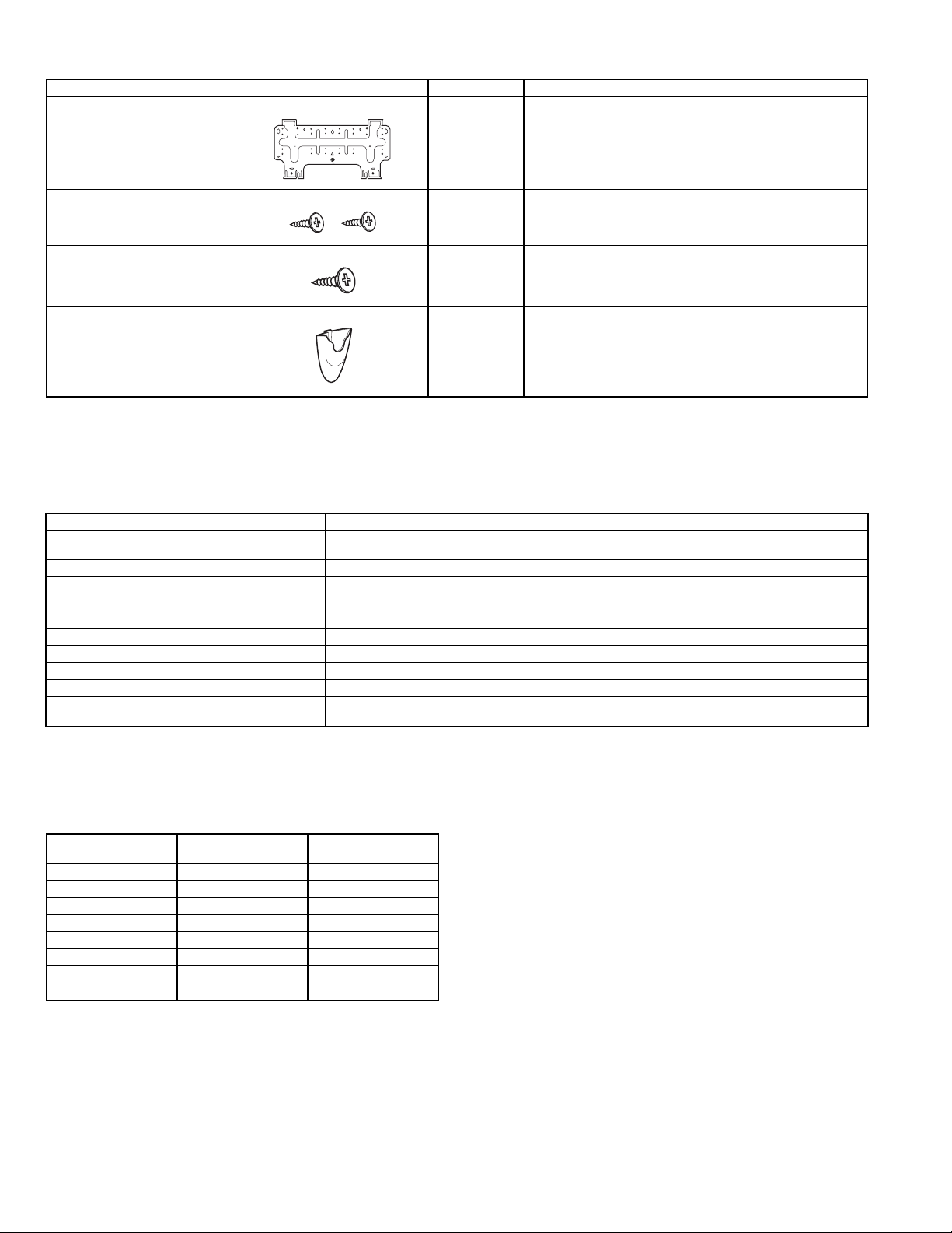
Table 1A — Installation Materials — Included In Shipment
DESCRIPTION QTY USAGE
Wall Hanging Bracket 1 For indoor unit installation.
Screws, 4xL10 2 For affixing unit and hanging bracket.
Screws, 5xL25 5/14*
Wireless Remote Control
Mounting Bracket
*619ENF01824, 619ENQ018,024: 5
619ENF,ENQ030,036: 14
Table 1B — Installation Materials — Field-Supplied
NAME SPECIFICATIONS
Connection Pipe (nominal capacity)
Wall Sleeve —
Wall Cap —
Finishing Tape PVC Film
Fastening Tape —
Pipe Insulation —
Drain Hose
Sealer Putty —
Power Supply Cable AWG 14 or higher
Electrical Connecting Cable Between
Indoor and Outdoor Unit
LEGEND
AWG — American Wire Gage
NEC — National Electrical Code
Liquid line:
Mixed Phase line:
5
/8 in. (619ENF01824 and 619ENQ018,024) 3/4 in. (619ENF,ENQ030,036)
Cable Type: AWG 14 synthetic rubber insulation with Neoprene coating, according to NEC codes.
3
/8 in. (619ENF,ENQ018-036)
5
/8 in. (619ENF01824 and 619ENQ018,024), 3/4 in. (619ENF,ENQ030,036)
For wall hanging bracket installation.
For wireless remote control mounting bracket installation.
1 For wireless remote control installation.
Table 2 — Matching Indoor Units to Outdoor Units See Fig. 2 for unit dimensions. Allow sufficient space for air-
OUTDOOR UNIT
538ENF018 Cooling Only 619ENF01824
538ENF024 Cooling Only 619ENF01824
538ENF030 Cooling Only 619ENF030
538ENF036 Cooling Only 619ENF036
538QNF018 Heat Pump 619ENQ018
538QNF024 Heat Pump 619ENQ024
538QNF030 Heat Pump 619ENQ030
538QNF036 Heat Pump 619ENQ036
COOLING ONLY OR
HEAT PUMP
INDOOR UNIT
flow clearance, wiring, refrigerant piping, and servicing
units. See Fig. 3.
Avoid mounting the unit in areas that are:
• exposed to direct sunlight
• too close to heat sources
• too close to humid conditions
• located in an area with oily ambient conditions.
—2—
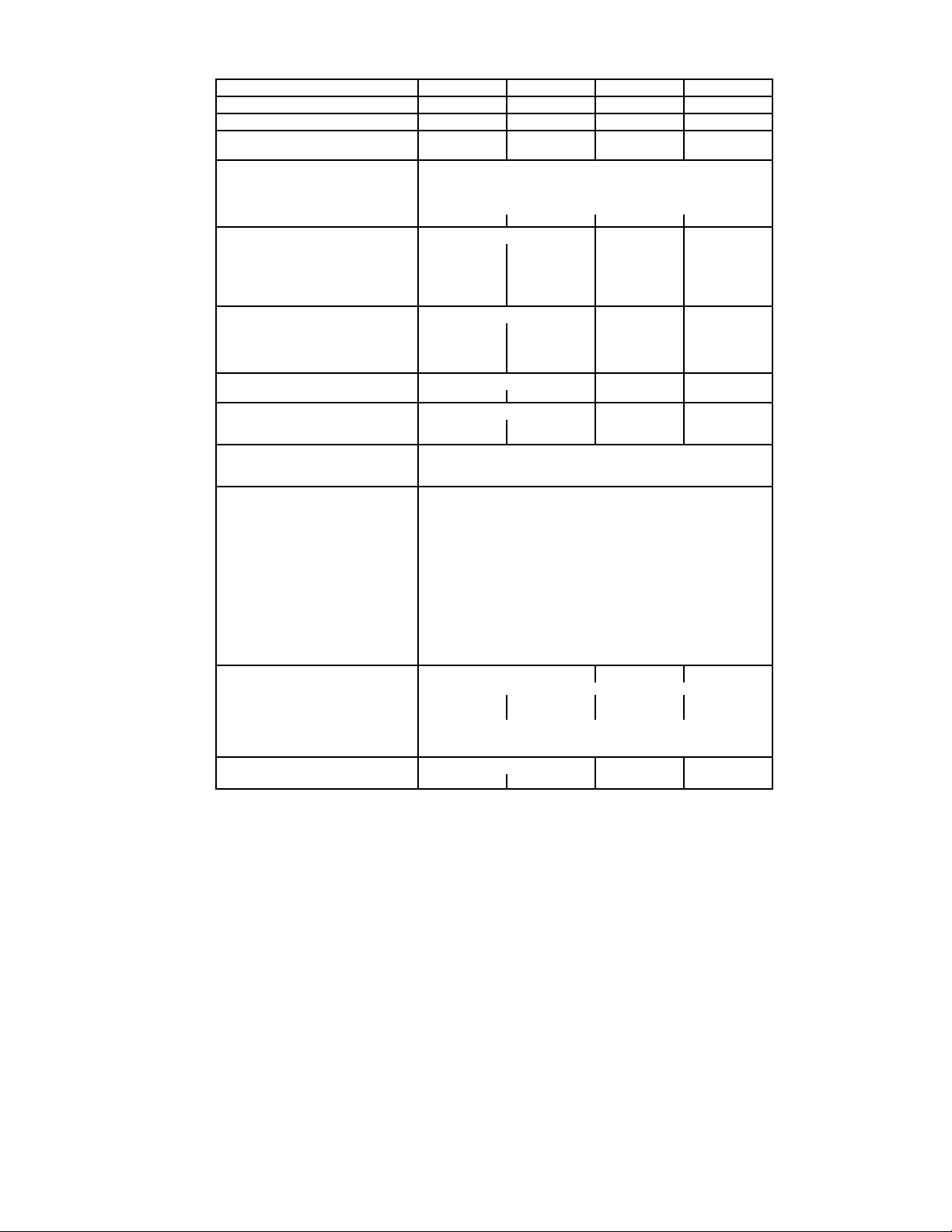
Table 3 — Indoor Unit Physical Data
SYSTEM SIZE 018 024 030 036
NOMINAL CAPACITY (Btuh) 18,000 24,000 30,000 36,000
OPERATING WEIGHT (lb) 31 31 51 51
MOISTURE REMOVAL RATE
(Pints/hr) (619ENF/ENQ)
REFRIGERANT
Type R-410A
Control Device (Cooling) Accurator Piston at Outdoor Unit
Control Device (Heating) Accurator Piston at Outdoor Unit
System Charge Required (lb)* 6.0 6.3 7.4 10.5
INDOOR FAN
Rpm/Cfm (High) 1335/645 1335/645 1030/730 1200/900
Rpm/Cfm (Med) 1120/525 1120/525 930/630 1050/750
Rpm/Cfm (Low) 1000/460 1000/460 830/530 900/600
Motor Watts 64 64 74 74
Blowers Quantity...Size 1...4.0 x 33.7 1...4.0 x 33.7 2...4.2 x 23.5 2...4.2 x 23.5
INDOOR COIL
Face Area (sq ft) 3.0 3.0 4.9 4.9
No. Rows 2222
FPI (619ENF/ENQ) 16/16 16/20 18/18 18/18
Circuits 5599
FILTERS
Quantity...Size (in.) 2...12.5 x 16.1 2...12.5 x 16.1 3...17.3 x 16.1 3...17.3 x 16.1
AIR SWEEP
Horizontal Manual Manual Automatic Automatic
Vertical Automatic Automatic Automatic Automatic
OPERATING LIMITS
Heating (Min/Max) —/81 F db
Cooling (Min/Max) 59 F wb, 70 F db/74 F wb, 90 F db
CONTROLS Integrated Microprocessor
Remote Controller Options Wireless, CRC
Diagnostics Ye s
Defrost Method Demand Defrost
Timer Mode Ye s
Warm Start Feature Ye s
Test Mode Ye s
Freeze Protection Ye s
Dehumidification Mode Ye s
Fan Mode Yes
Auto Changeover Ye s
Auto Restart Ye s
Control Voltage 24v
System Voltage 208/230
REFRIGERANT LINES
Connection Type Flare
Mixed Phase Line (in.) OD
Vapor Line (in.) OD
Max Length (ft) 200
Max Lift (Fan coil above) (ft) 60
Max Drop (Fan coil below) (ft) 60
CONDENSATE DRAIN
Size (in.)
LEGEND
CRC — Carrier Room Controller
db — dry bulb
FPI — Fins Per Inch
wb — wet bulb
*Factory charge is based on 25 ft of interconnecting line.
5.4/5.2 7.9/7.9 8.8/9.2 13.0/12.8
3
/
8
5
/
8
5
/8 OD, 7/16 ID
3
/
8
5
/
8
5
/8 OD, 7/16 ID3/4 OD, 5/9 ID3/4 OD, 5/9 ID
3
/
8
3
/
4
3
/
8
3
/
4
—3—
619ENF,ENQ
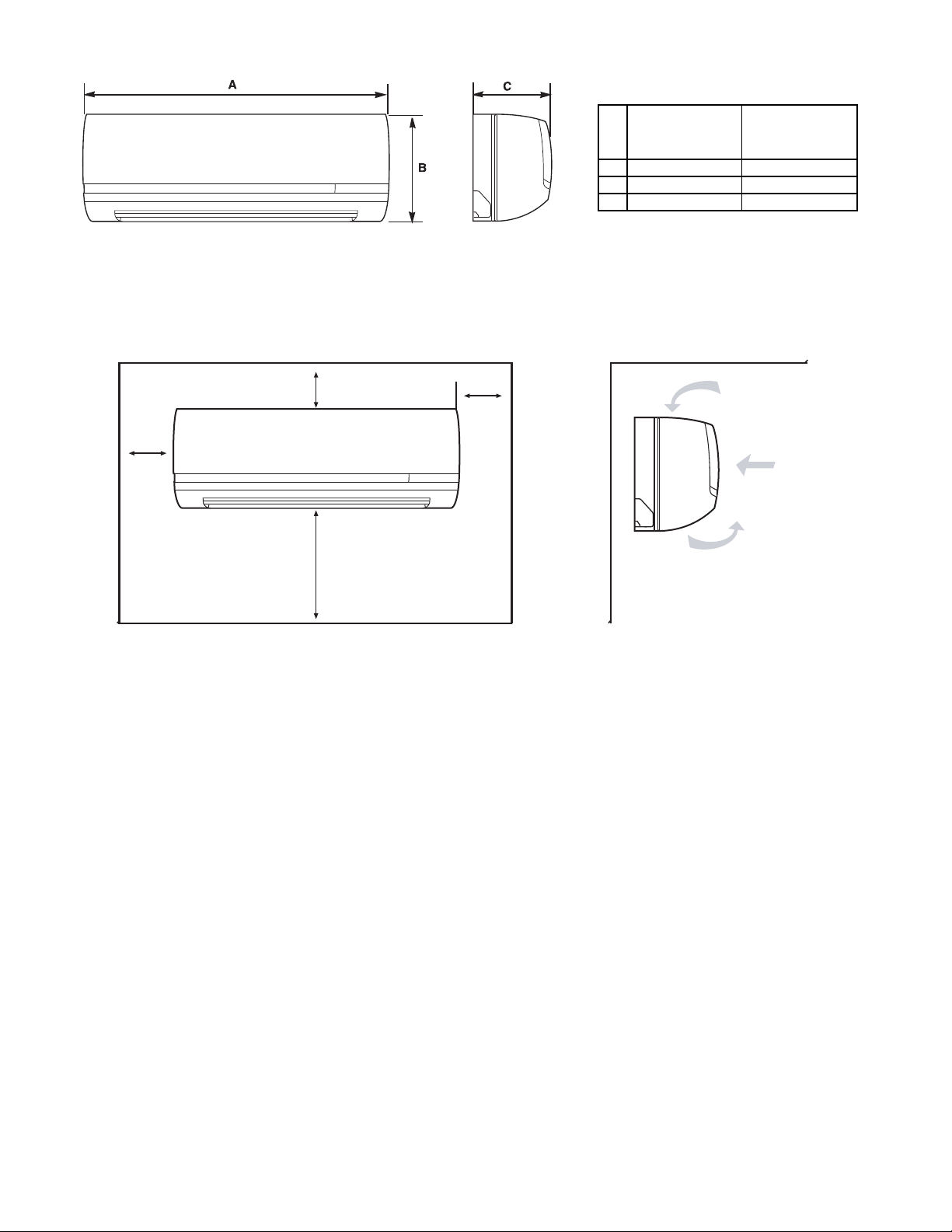
Fig. 2 — Unit Dimensions
619ENF01824
619ENQ018,024
DIMENSIONS
(in.)
619ENF,ENQ
030, 036
DIMENSIONS
(in.)
A 42.5 57.5
B 11.6 13.4
C 7.9 9.5
4 in.
min.
4 in.
min.
80 in.
min.
8 in.
min.
619ENF,ENQ UNITS
Fig. 3 — Unit Clearances
—4—
II. STEP 2 — MOUNT UNIT
Before mounting the 619ENF,ENQ unit on the wall with a
wall hanging bracket, consider how the unit will be
connected to the refrigerant piping. The indoor unit can be
connected in four ways. Refer to Fig. 4 for connection options.
When the piping is connected to points 1, 2 or 4, remove the
knockout either at the side or at the bottom of the unit.
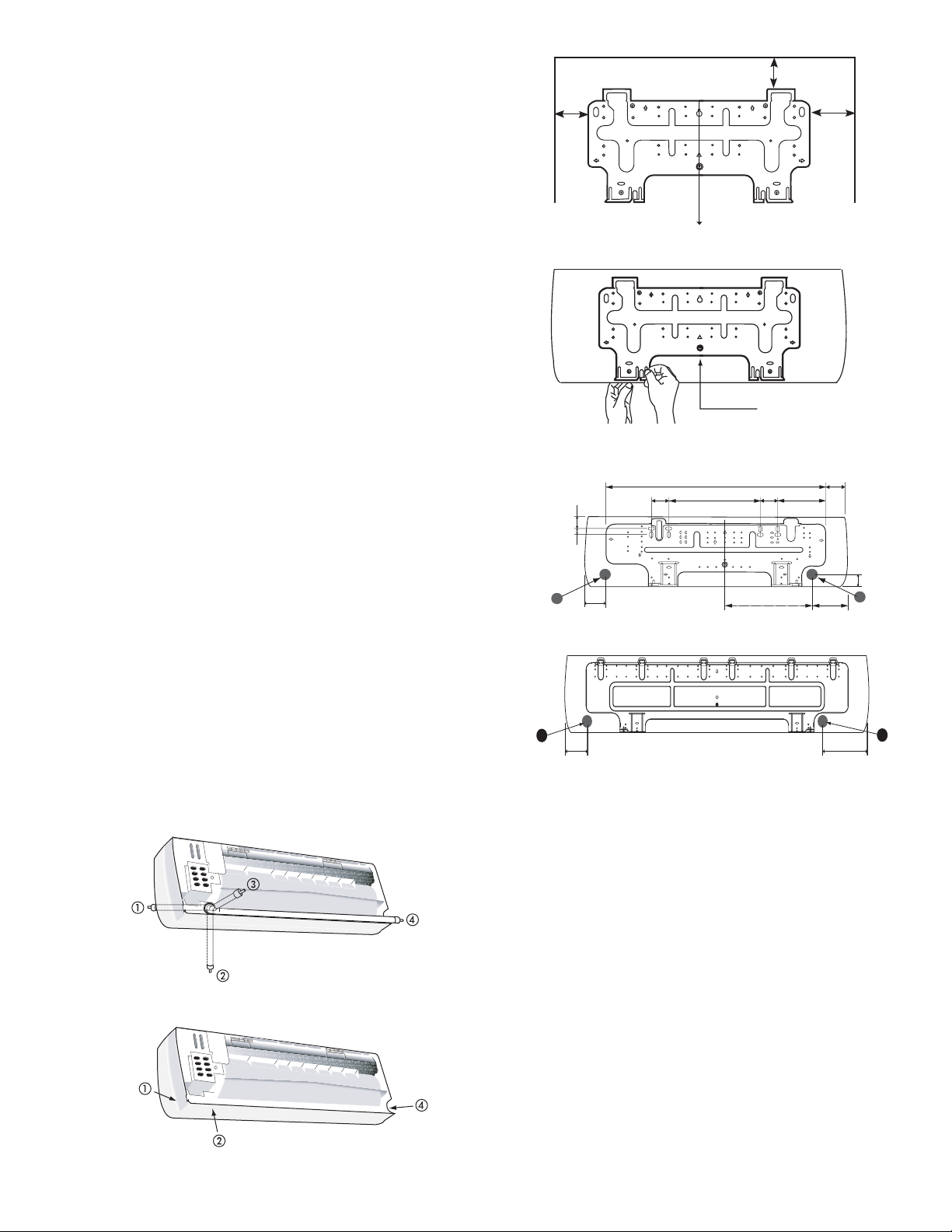
The indoor units are mounted on the wall with a wall hanging bracket. Position the wall hanging bracket so that it is
flush with the wall. See Fig. 5 for service clearances. See
Fig. 6 for wall bracket dimensions.
Complete the following when installing the wall hanging
bracket:
1. Before installing the wall hanging bracket to the wall
remove it from the indoor unit by pushing at the indicated pressure points at the bottom of the unit.
2. Install the wall hanging bracket in a location that is
strong enough to withstand the weight of the unit.
3. Install the wall hanging bracket so that it is level.
Use a plumb line if necessary.
NOTE: Be sure that the wall hanging bracket is level. If the
wall hanging bracket is not level water will leak from the
indoor unit.
4. Fasten the wall hanging bracket to the wall with 4 or
more screw anchors through the holes near the outer
edge of the bracket.
5. Install the wall hanging bracket flush to the wall,
and ensure the bracket does not move.
6. If the unit is removed from the wall hanging bracket
after installing it on to the wall, remove it by pushing up
on the indicated marks at the bottom of the unit body.
III. STEP 3 — COMPLETE REFRIGERANT PIPING
CONNECTIONS
When running the piping for indoor units the piping can be connected as rear piping or side or bottom piping. Refer to Fig. 4.
A. Rear Piping
Route the piping behind the indoor unit so that the piping is
concealed by the unit. For rear piping installation drill a
1
/2 in. diameter hole in the wall at point A or B in Fig. 6. Drill
2
the hole at a slope so that the outside end is lower (
1
/2 in.) than the inside end to ensure optimal drainage. Refer
1
/4 in. to
to Fig. 7. Pass the pipe through the hole.
Fig. 4 — Indoor Unit Piping Configurations
5 in. min.
12 in.
min.
Plumb line
Remove Screw
Fig. 5 — Installing the Wall Bracket
2.1"
1"
2"
A
A
2"
35.4"
2.8"
619ENF01824, 619ENQ018,024
619ENF, ENQ030,036
14.9"
2.8"
13.8
18 in.
min.
3.5"
7.7"
2.1"
B
5.1
"
"
B
5.1"
Fig. 6 — Wall Bracket Dimensions
B. Side or Bottom Piping
Remove the knockout in the unit and pass the piping
through the wall. The pipe should slope downward and away
from the unit to ensure optimal drainage.
C. Routing the Drain Hose and Refrigerant Piping
The drain hose and drain cap are assembled as shown in
Fig. 8 in the factory. To do right-side (1), right-bottom (2) or
right-back (3) piping in Fig. 4 draw the drain hose to rightside piping direction. (It is not always necessary to exchange
the location of drain hose and drain cap.)
1. Tie together the refrigerant piping, the drain hose,
and the electrical connection wire.
2. Route the refrigerant piping in the required direction, and bend carefully avoiding pipe deformation.
3. Bind the drain hose and the electrical connection
wire together with fastening tape.
4. The drain hose should be at the bottom. See Fig. 9
and 10.
5. For left-hand piping, fit the pipes and the wiring into
the recess at the back of the unit.
—5—
 Loading...