

Page 1
Installation, start-up and
619CNF
service instructions
CEILING-SUSPENDED
FAN COIL UNITS
CONTENTS
Page
SAFETY CONSIDERATIONS . . . . . . . . . . . . . . . . . . . . . . . . . 1
INSTALLATION . . . . . . . . . . . . . . . . . . . . . . . . . . . . . . . . . .1-17
I. Step 1 — Complete Pre-Installation
Checks . . . . . . . . . . . . . . . . . . . . . . . . . . . . . . . . . . . . 3
II. Step 2 — Select Location . . . . . . . . . . . . . . . . . . . . . 4
III. Step 3 — Mount Unit . . . . . . . . . . . . . . . . . . . . . . . . . 6
IV. Step 4 — Connect Refrigerant Piping . . . . . . . . . . . 7
V. Step 5 — Connect Condensate Drain Line . . . . . . . 8
VI. Step 6 — Make Electrical Connections . . . . . . . . . 10
VII. Step 7 — Install Thermostat . . . . . . . . . . . . . . . . . . 12
VIII. Step 8 — Make Connections Between
Indoor and Outdoor Units . . . . . . . . . . . . . . . . . . . . 15
START-UP . . . . . . . . . . . . . . . . . . . . . . . . . . . . . . . . . . . . .18,19
I. After Extended Shutdown. . . . . . . . . . . . . . . . . . . . 18
II. Seasonal Changeovers . . . . . . . . . . . . . . . . . . . . . . 18
III. Adjusting Airflow . . . . . . . . . . . . . . . . . . . . . . . . . . . 18
IV. Operating Mode Memory. . . . . . . . . . . . . . . . . . . . . 18
V. Automatic Operation (Auto.) Mode. . . . . . . . . . . . . 18
VI. Operating Sequence . . . . . . . . . . . . . . . . . . . . . . . . 18
CLEANING AND MAINTENANCE . . . . . . . . . . . . . . . . . . 19,20
I. Lubrication . . . . . . . . . . . . . . . . . . . . . . . . . . . . . . . . 19
II. Air Filters . . . . . . . . . . . . . . . . . . . . . . . . . . . . . . . . . 19
III. Clean Indoor Unit Bottom Panel. . . . . . . . . . . . . . . 20
IV. Clean Indoor Coil. . . . . . . . . . . . . . . . . . . . . . . . . . . 20
V. Clean Outdoor Coil (Outdoor Unit). . . . . . . . . . . . . 20
VI. Clean Condensate Drains . . . . . . . . . . . . . . . . . . . . 20
SERVICE . . . . . . . . . . . . . . . . . . . . . . . . . . . . . . . . . . . . . . . . 20
I. Before Calling for Service. . . . . . . . . . . . . . . . . . . . 20
FRESH AIR INSTALLATION OPTION . . . . . . . . . . . . . . . . . 20
I. Ventilation-Air Accessory . . . . . . . . . . . . . . . . . . . . 20
TROUBLESHOOTING. . . . . . . . . . . . . . . . . . . . . . . . . . . . 20,21
START-UP CHECKLIST . . . . . . . . . . . . . . . . . . . . . .CL1, CL-2
619CNQ
Sizes 024-060
Cancels: II 619C-24-3 II 619C-24-4
4/15/06
performed by trained service personnel. When working on
air-conditioning equipment, observe precautions in literature
and on tags and labels attached to unit.
Follow all safety codes. Wear safety glasses and work gloves.
Use quenching cloth for brazing operations. Have fire
extinguisher available. Read these instructions thoroughly.
Consult local building codes and National Electrical Code
(NEC) for special installation requirements.
WARNING: Before installing or servicing system,
always turn off main power to system. There may be
more than one disconnect switch. Turn off accessory
heater power if applicable. Electrical shock can cause
personal injury.
INSTALLATION
Installation instructions for fan coil units (Fig. 1) are contained in this manual. Refer to this manual for proper installation of the complete system. Note that the outdoor units are
shipped with installation and service instructions for basic
installation of the outdoor section. Be sure to make the connections in Cooling Only Systems and Heat Pump Systems
sections on page 15 of this literature so that the unit will
operate properly.
Refer to Table 1 for proper system matches.
SAFETY CONSIDERATIONS
Installing and servicing air-conditioning equipment can be
hazardous due to system pressure and electrical components.
Only trained and qualified service personnel should install or
service air-conditioning equipment.
Untrained personnel can perform basic maintenance, such as
cleaning and replacing filters. All other operations should be
a40-267
Fig. 1 — Ceiling-Suspended Fan Coil Unit
Page 2
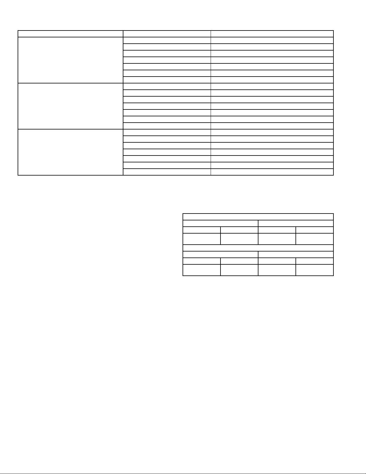
Table 1 — System Matches
SYSTEM TYPE INDOOR SECTION NUMBER OUTDOOR SECTION NUMBER
619CNF 538ANR,APR,AER
024* 018
024 024
Cooling Only
Heat Pumps
Heating/Cooling
*Units must be field reconfigured for 11/2 ton (18,000 Btuh) operation. See Before Installation section on page 3 for details.
NOTE: Numbers in ( ) indicate quantities when there is more than one fan coil unit in the system.
036 030
036 036
048 048
060 060
619CNQ 538BNR,BPR,BER
024* 018
024 024
036 030
036 036
048 048
060 060
619CNQ 538ANR,APR,AER
024* 018
024 024
036 030
036 036
048 048
060 060
Ensure unit operation within the application guidelines
shown in Table 2. When installing the outdoor unit, for cooling operation when the outdoor-air temperature is below
55 F, the following accessories are required:
• low ambient kit
• crankcase heater
• winter start kit
• isolation relay (538B heat pump units only)
This will provide cooling operation down to 40 F ambient
temperature. For operation down to –20 F ambient temperature, a field-installed wind baffle will also be required.
To complete installation of the system, the following items
must be field-supplied for connection of the indoor and
outdoor units:
• refrigerant piping
• condensate drain piping
• thermostat
•wiring
For some applications, a fresh air intake, power vent fan,
and/or condensate pump kit may be required. Refer to
Tables 3A and 3B for physical data.
Table 2 — Application Range
COOLING
Maximum Minimum
Indoor Outdoor Indoor Outdoor
95 F DB
71 F WB
Maximum Minimum
Indoor Outdoor Indoor Outdoor
80 F DB
71 F WB
LEGEND
DB — Dry Bulb
WB — Wet Bulb
*This value is for single-zone systems and may be equipped with an
accessory low-ambient control or winter start kit that will allow operation down to –20 F.
125 F DB 67 F DB
HEATING (Heat Pump Systems Only)
75 F DB
65 F WB
57 F WB
55 F DB –20 F DB
55 F DB*
40 F DB
—2—
Page 3
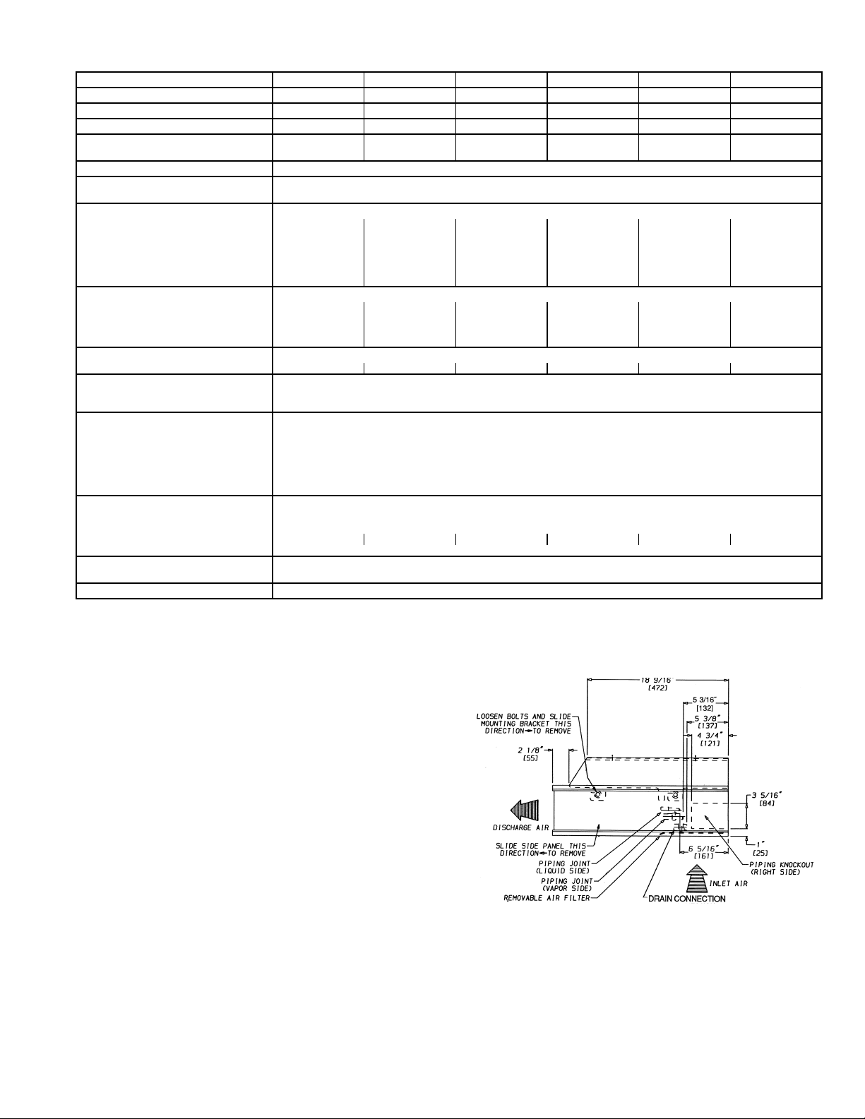
Table 3A — Physical Data, Under Ceiling Cooling Only Units
SYSTEM SIZE 018* 024 030 036 048 060
NOMINAL CAPACITY (tons) 1
1
/
2
23345
NOMINAL SIZE (Btuh) 18,000 24,000 30,000 36,000 48,000 60,000
OPERATING WEIGHT (lb) 108 108 117 117 149 179
MOISTURE REMOVAL WEIGHT
(Pints/Hr)
4.0 7.3 6.0 9.0 13.0 14.5
FINISH GM Motorhome White with Black Trim
REFRIGERANT R-410A
Control (Cooling) AccuRater Control
INDOOR FAN Direct Drive Centrifugal
Rpm...Cfm High 862...500 1050…600 1275...840 1275...840 1435...1200 1275...1600
Rpm...Cfm Medium 690...400 690...400 972...740 972...740 1388...1160 972...1220
Rpm...Cfm Low 552...320 552...320 830...640 830...640 1315...1100 830...1040
High Speed Watts 92 92 282 282 425 564
Motor Quantity 111122
Blowers — No. ...Size (in.) 2...6x8 2…6x8 2…6x8 2…6x8 3…6x8 4…6x8
INDOOR COIL Copper Tube, Aluminum Fin
Face Area (sq ft) 2.2 2.2 2.6 2.6 3.0 4.0
No. of Rows 444444
Fins/in. 14.9 14.9 14.9 14.9 14.9 14.9
Circuits 444488
FILTERS Cleanable
Quantity 445568
AIRSWEEP
Horizontal User select ON/OFF
Vertical Manual
CONTROLS
Control Voltage 24 V
Auto Restart Ye s
Fan Speed High/Medium/Low
Condensate Pump Safety Yes (Accessory)
Indoor Coil Freeze Protection Standard shutoff at 28 F
Filter Change Indication 250 Hours of Indoor Fan Operation
REFRIGERANT LINES
Connection Type Flare
Liquid Line OD (in.)
Vapor Line OD (in.)
Max Line Length For maximum line lengths see condensing unit instructions.
CONDENSATE DRAIN
CONNECTION
5
/
8
5
/
8
3
CONDENSATE DRAIN SIZE (in.)
*Field reconfigured to 18,000 Btuh (11/2 tons). See Before Installation
section on this page for details.
†The valve connection size is 7/8 inch. The recommended line size is
11/8 inch.
3
/
/
4
8
Pipe Thread (MPT)
3
/
4
3
/
4
7
/
8
7
/8†
I. STEP 1 — COMPLETE PRE-INSTALLATION CHECKS
A. Unpack Unit
Store fan coil unit in the original packaging until it is moved
to the final site for installation. When removing unit from
carton, lift unit by its 4 corners; DO NOT lift unit by its
plastic parts.
B. Inspect Shipment
Upon receipt of shipment, check fan coil unit for damage.
Forward claim papers directly to the transportation company. Manufacturer is not responsible for damage incurred
in transit.
Check all items; if any item is missing, notify your dealer. To
prevent loss or damage, leave all parts in original packages
until installation.
C. Before Installation
Perform the following steps before installing indoor fan coil
unit. Place the indoor unit upside down on the floor, then:
1. Remove side panels by sliding forward, then away
from sides of unit (Fig. 2). Reinstall prior to unit
start-up.
2. Remove air filters from inlet grilles; then remove and
retain screws securing inlet grilles to indoor unit.
Reinstall prior to unit start-up.
a40-928
NOTE: Dimensions shown in brackets [ ] are in mm.
Fig. 2 — Removal of Mounting Brackets
from Indoor Unit
—3—
Page 4
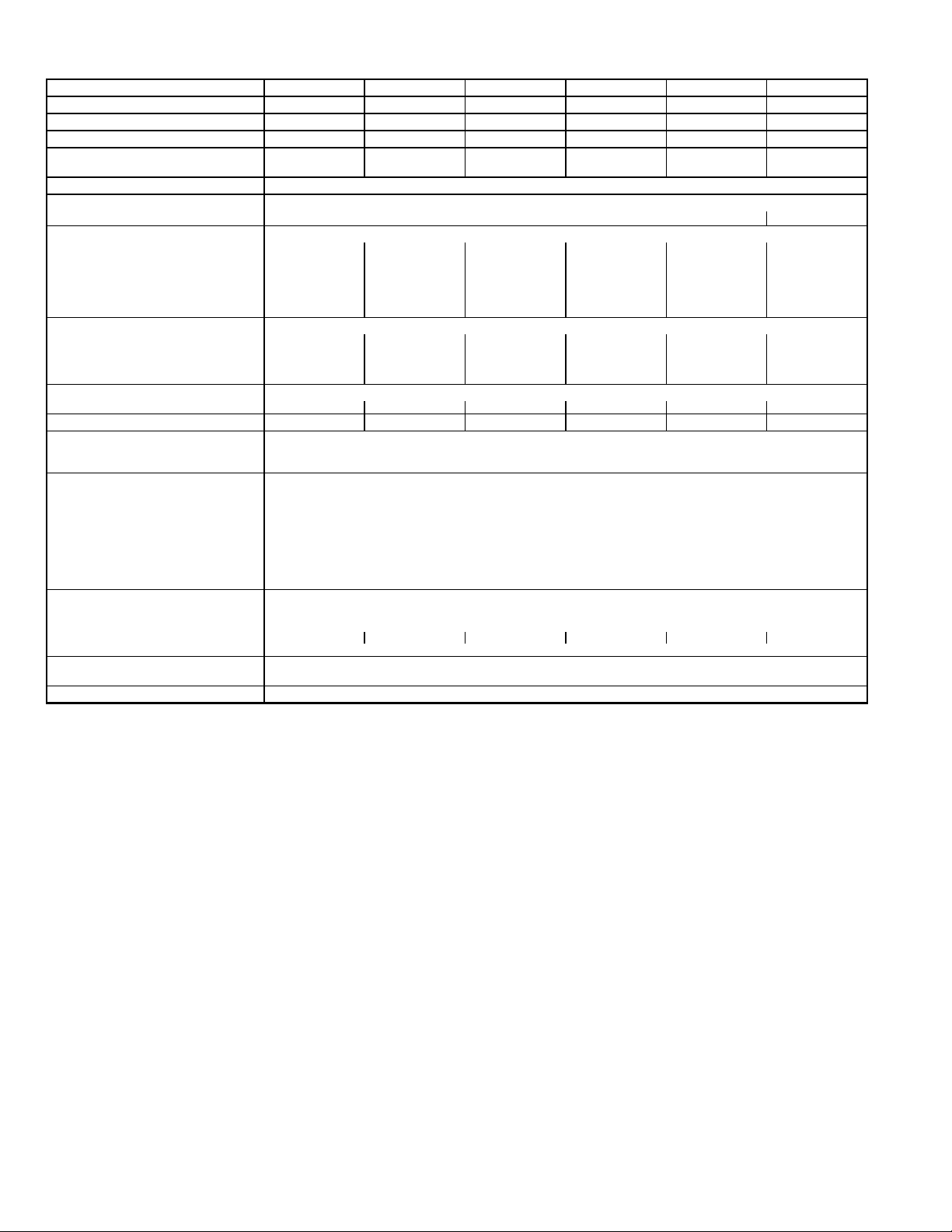
Table 3B — Physical Data, Under Ceiling Heat Pump Units
UNIT SIZE 018* 024 030 036 048 060
NOMINAL CAPACITY (tons) 1
1
/
2
23345
NOMINAL SIZE (Btuh) 18,000 24,000 30,000 36,000 48,000 60,000
OPERATING WEIGHT (lb) 110 110 119 119 151 181
MOISTURE REMOVAL WEIGHT
(Pints/Hr)
4.0 7.3 6.0 9.0 13.0 14.5
FINISH GM Motorhome White with Black Trim
REFRIGERANT R-410A
Control (Cooling) AccuRater Control
TXV
INDOOR FAN Direct Drive Centrifugal
Rpm...Cfm High 900…480 1050…550 1275...840 1275...840 1435...1130 1275...1600
Rpm...Cfm Medium 862...400 900…480 972...740 972...740 1388... 975 972...1220
Rpm...Cfm Low 770...320 862...400 830...640 830...640 1315... 820 830...1040
High Speed Watts 92 92 282 282 425 564
Motor Quantity 111122
Blowers — No. ...Size (in.) 2...6x8 2...6x8 2...6x8 2...6x8 3...6x8 4...6x8
INDOOR COIL Copper Tube, Aluminum Fin
Face Area (sq ft) 2.2 2.2 2.6 2.6 3.0 4.0
No. of Rows 444444
Fins/in. 14.9 14.9 14.9 14.9 14.9 14.9
Circuits 444488
FILTERS Cleanable
Quantity 445568
HEATERS (kW) 2.0 2.0 3.0 3.0 4.0 5.0
AIRSWEEP
Horizontal User select ON/OFF
Vertical Manual
CONTROLS
Control Voltage 24 V
Defrost Method Timed
Dehumidification Ye s
Auto Restart Ye s
Fan Speed High/Medium/Low
Condensate Pump Safety Yes (Accessory)
Filter Change Indication 250 Hours of Indoor Fan Operation
Freeze Protection Indoor coil less than 28 F, resets at 50 F.
REFRIGERANT LINES
Connection Type Flare
Liquid Line OD (in.)
Vapor Line OD (in.)
Max Line Length For maximum line lengths see condensing unit instructions.
5
/
8
5
/
8
3
CONDENSATE DRAIN
CONNECTION
CONDENSATE DRAIN SIZE (in.)
*Field reconfigured to 18,000 Btuh (11/2 tons). See Before Installation
section on page 3 for details.
†The valve connection size is 7/8 inch. The recommended line size is
1
1
/8 inch.
3
/
/
4
8
Pipe Thread (MPT)
3
/
4
3
/
4
7
/
8
7
/8†
3. Remove inlet grilles from indoor unit by sliding forward. Reinstall prior to unit start-up.
IMPORTANT: If necessary, reconfigure the 24,000 Btuh fan coil
unit to 18,000 Btuh. Unplug the fan motor at the control box
harness and plug into the 619CN018 marked connector.
II. STEP 2 — SELECT LOCATION
Consult local building codes and NEC for special installation
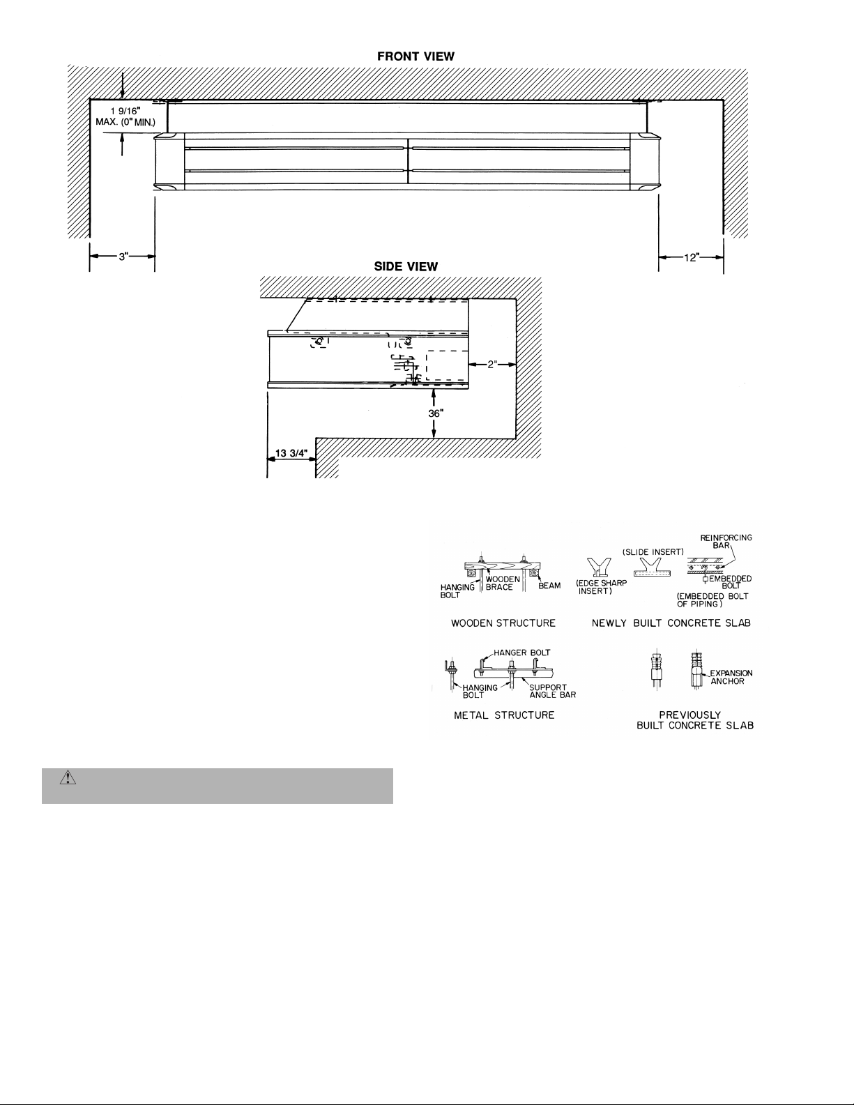
requirements. See Fig. 3 and 4 for unit dimensions and
required clearances.
There are several ways the unit may be installed to different
types of ceiling construction. These instructions do not cover
all installation methods. As a typical installation, these
instructions focus primarily on mounting the unit to metal in
new construction. Plan the installation carefully before you
begin. Listed below are some guidelines that should be followed when determining location for the unit.
1. Place unit adjacent to an outside wall if fresh air is
required, ensuring that location allows for complete
air distribution.
2. Locate the thermostat in an area that is not subjected
to drafts or direct sunlight through windows. Locate
the thermostat on an internal wall whenever possible.
3. Allow sufficient clearance for airflow, wiring, refrigerant piping, and servicing unit (Fig. 3 and 4).
4. Make sure the unit is easily accessible to electrical
power.
—4—
Page 5
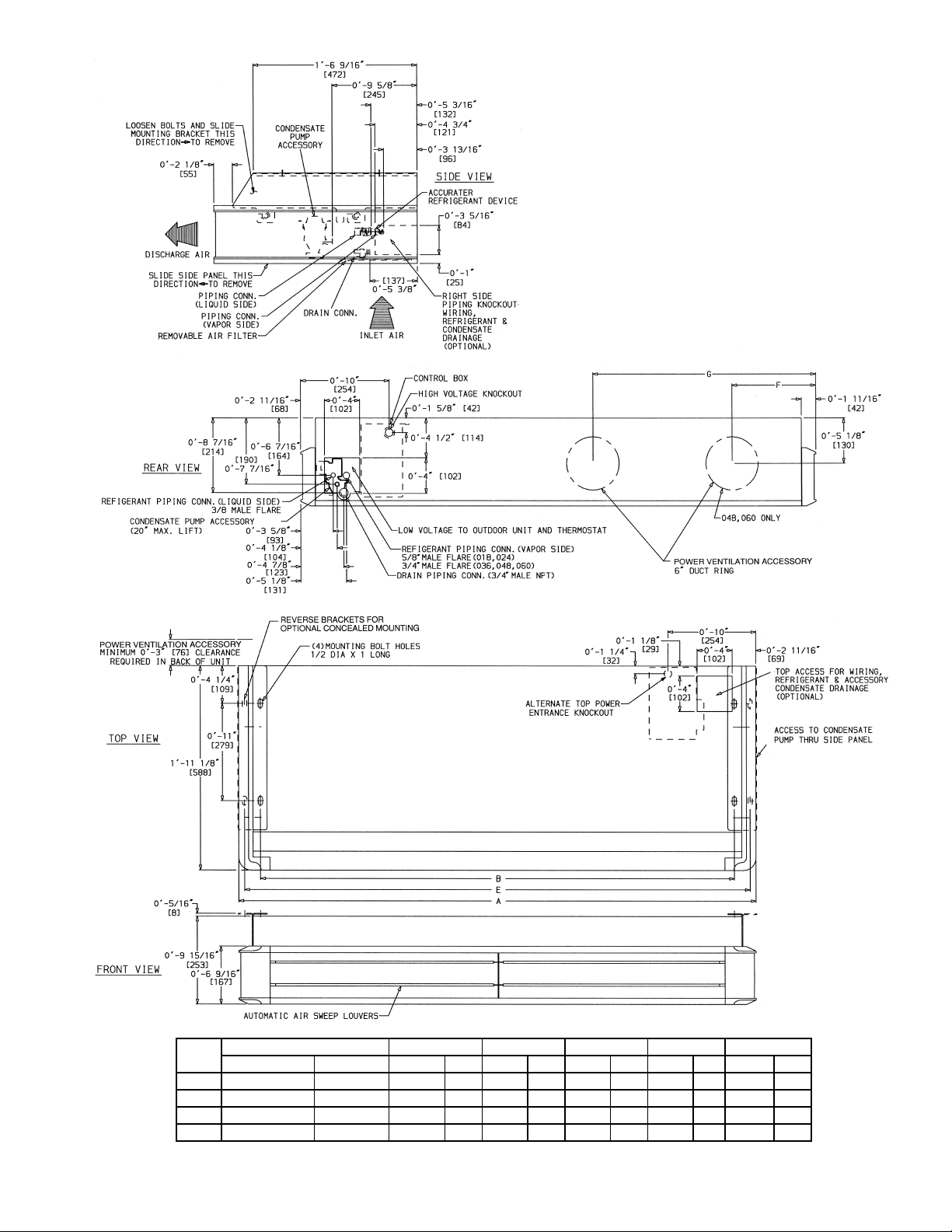
NOTES:
1. Dimensions in [ ] are in millimeters.
2. Direction of airflow.
3. Standard unit clearances are as follows:
•0″ on top and rear
•3″ on left side
•12″ on right side
•36″ on bottom
(When facing unit discharge.)
b40-437
UNIT
SIZE
024 108 110 4- 2
036 117 119 4-10
048 149 151 5-11
060 179 181 7- 8 2336 7- 3 2211 7- 6
WEIGHT (lb) A B E F G
Cooling Only Heat Pump ft-in. mm ft-in. mm ft-in. mm ft-in. mm ft-in. mm
15
/161294 3-10 1169 4- 15/81260 — — 1- 95/8549
13
/161493 4- 57/81368 4- 91/21459 — — 2- 11/2648
9
/161817 5- 65/81692 5-101/41783 1- 97/8555 3- 31/16992
5
/82302 1-115/8601 4-119/161512
Fig. 3 — Base Unit Dimensions
—5—
Page 6
a40-929
Fig. 4 — Fan Coil Unit Clearances
5. Run refrigerant piping as directly as possible and
avoid any unnecessary turns or bends.
6. Condensate piping can be directed through the inside
wall to an approved drain or straight outside.
NOTE: The piping hole for condensate line must slope at a
1
minimum pitch of
/4 in. per foot to ensure proper drainage.
If proper pitch cannot be achieved, install accessory condensate pump at this time.
III. STEP 3 — MOUNT UNIT
Refer to Fig. 4 for clearances and dimensions. Use mounting
template included inside box to locate mounting bolt holes,
piping holes, electrical connections, and accessory outdoorair intake, if used.
Select proper type of hardware from the guidelines below.
See Fig. 5.
CAUTION: Solid structure in ceiling must be used
due to the weight of the unit.
A. Wooden Structure
Install hanging bolts on a square wooden piece placed over
beams.
B. Newly Built Concrete Slab
Install hanging bolts with inserts, embedded bolts, etc.
C. Metal Structure
Install hanging bolts utilizing an existing angle or by installing a new support angle.
D. Previously Built Concrete Slab
Install hanging bolts with expansion anchor.
E. To Mount Unit:
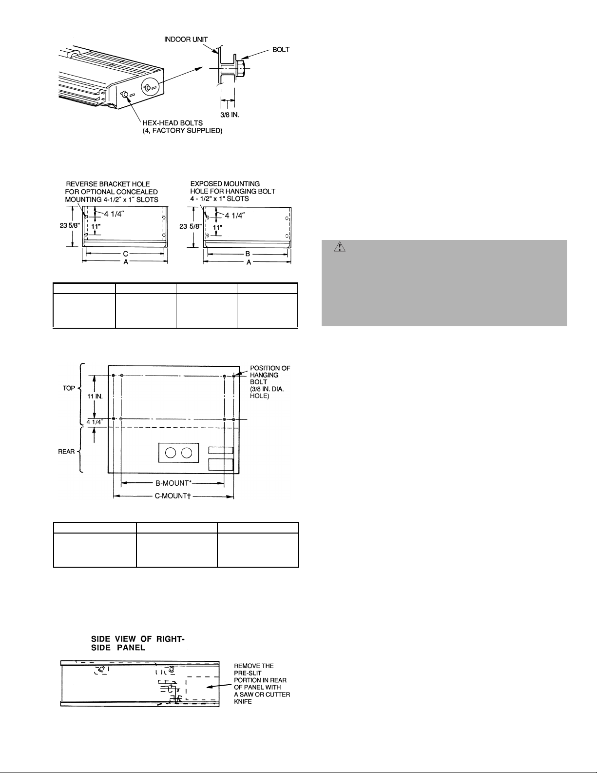
1. Remove mounting bracket and reinstall the 2 hexhead bolts (factory-supplied) into each side of indoor
a40-524
Fig. 5 — Fan Coil Unit Mounting Methods
(Hardware is Field-Supplied)
unit as shown in Fig. 6. Allow approximately
space between bolt head and unit.
2. Determine installation position, paying particular
attention to piping lengths, wiring connections, clearances, etc. See Fig. 3 for connection locations, Fig. 4
for clearances, and Fig. 7 and 8 for bolt locations.
3. Open knockout if right-side piping connections are
required (Fig. 9), by removing the pre-slit portion in
the rear of the right side panel with a saw or cutter
knife.
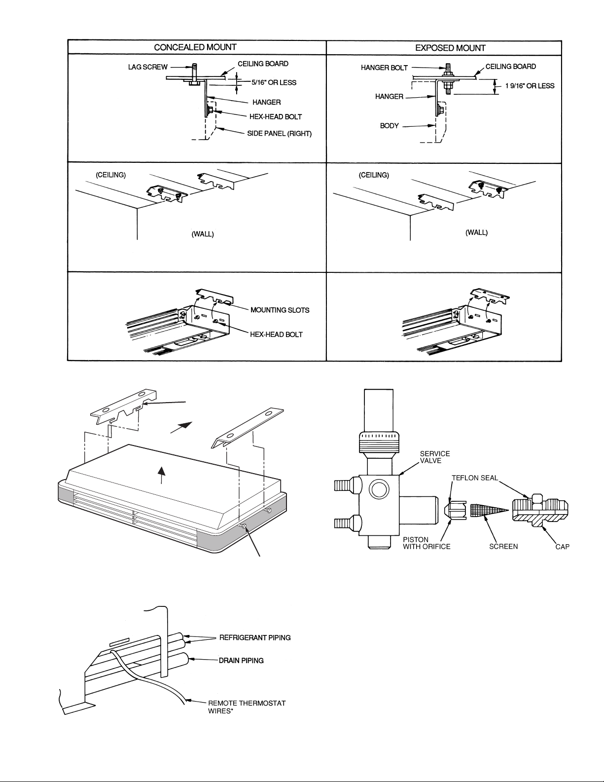
4. Mount hanging brackets on ceiling (Fig. 10) for either
concealed or exposed bolt hanging position.
5. Lift the unit into place, and fit the hex-head bolts on
sides of indoor unit into mounting slots of mounting
brackets (Fig. 11). Ensure unit is mounted with a
slight tilt to the right rear side for proper drainage.
6. Tighten indoor unit hex-head bolts securely.
3
/8-in.
—6—
Page 7
a40-620
Fig. 6 — Installing Hex-Head Mounting Bolts
in Fan Coil Unit
a40-930
DIMENSIONS (in.)
UNIT SIZE A B C
024 50
036 5813/
048 719/
060 92 87 905/
15
/
16
16
16
46 495/
537/
8
665/
8
Fig. 7 — Fan Coil Unit Hanging Dimensions
a40-1464
DIMENSIONS (in.)
UNIT SIZE B C
024 46 49
036 537/
048 665/
060 87 905/
*Exposed mounting holes.
†Reverse bracket holes (concealed mounting).
8
8
Fig. 8 — Mounting Included with
Fan Coil Unit
Fig. 9 — Removing Rear Knockout in Side Panel
if Right-Side Piping Connection is Used
571/
701/
5
/
8
571/
2
701/
4
8
a40-932
F. To Install Thermostat:
3
If there is at least
/8 in. of space between the back of indoor
unit and wall:
1. Route thermostat wires (field-supplied) through slot
in right side or rear panel of indoor unit (Fig. 3).
2. Route wires over refrigerant and drain piping as
shown in Fig. 12.
IMPORTANT: Do not route wires under the piping, or wires
could impede air filter removal.
IV. STEP 4 — CONNECT REFRIGERANT PIPING
Fan coil units may be connected to outdoor units using fieldsupplied refrigerant grade piping. Refer to Tables 3A and 3B
for the correct size piping. The length of refrigerant pipe
depends on the unit placement and building structure; run
pipes as directly as possible. For piping requirements over
50 ft of total run, or more than 25 ft of lift, consult the
Residential Long Line Application Guide.
CAUTION: DO NOT BURY MORE THAN 36 IN.
OF REFRIGERANT PIPE IN THE GROUND. If any
section of pipe is buried, there must be a 6-in. vertical
rise to the valve connections on the outdoor unit. If
more than the recommended length is buried, refriger-
8
2
4
8
ant may migrate to the cooler, buried section during
extended periods of unit shutdown, causing refrigerant
slugging and possible compressor damage at start-up.
To connect piping:
1. Install insulation. It is extremely important that all
refrigerant lines and the metering device be
insulated on heat pumps and multi-splits. On cooling
only units, the liquid line may be left uninsulated.
Use any acceptable heat resistant closed-cell foam
3
insulation (minimum
/8-in. wall thickness). When
insulating piping, cap ends and slide insulation over
the piping. Insulation can also be cut and placed over
piping.
2. Run liquid and gas refrigerant piping.
a. Run pipes as directly as possible, and avoid any
unnecessary turns and bends.
b. Suspend refrigerant pipes so that the insulation
is not damaged and vibrations are not transmitted to the structure.
c. Leave slack in the refrigerant pipe between the
structure and the unit to absorb vibrations.
d. A piston is shipped in the factory-installed
metering device body (Fig. 13) with the indoor
unit. Use Tables 4A-4C to verify that you have
the required piston size for the system being
installed.
IMPORTANT: The metering device is factory-installed and
only needs to be replaced for long line applications or if the
system combination requires it. See Tables 4A-4C. See
Fig. 13.
e. For special applications such as long lines or
raised elevations, consult the Residential Long
Line Application Guide for specific system
requirements. The arrow on the metering device
body must face away from the indoor coil.
f. Refer to the outdoor unit Installation, Start-Up and
Service Instructions for additional information.
g. Install a factory-supplied filter drier near the
outdoor unit. On heat pump systems, a bi-flow
filter drier must be used.
—7—
Page 8
3. Insulate and caulk wall openings to reduce air infiltration and refrigerant pipe vibrations on structure.
4. Evacuate piping, if necessary. If either refrigerant
piping or the indoor coil is exposed to atmospheric
conditions, it must be evacuated to 1000 microns to
eliminate contamination and moisture in the system.
V. STEP 5 — CONNECT CONDENSATE DRAIN LINE
Observe all local sanitary codes when installing condensate
drains. Refer to Fig. 3 and 14 for drain pipe connection from
indoor unit.
1. Use hard polyvinyl chloride (PVC) pipe material with
3
nominal ID of
insulation
/4 in. to connect at drain line. Use pipe
1
/4-in. thick, such as Armaflex insulation,
on exposed piping inside the conditioned space.
2. To ensure regular flow of condensate water, the drain
pipe should be pitched toward an open drain or sump
1
at a downward slope of at least
/4-in. per ft.
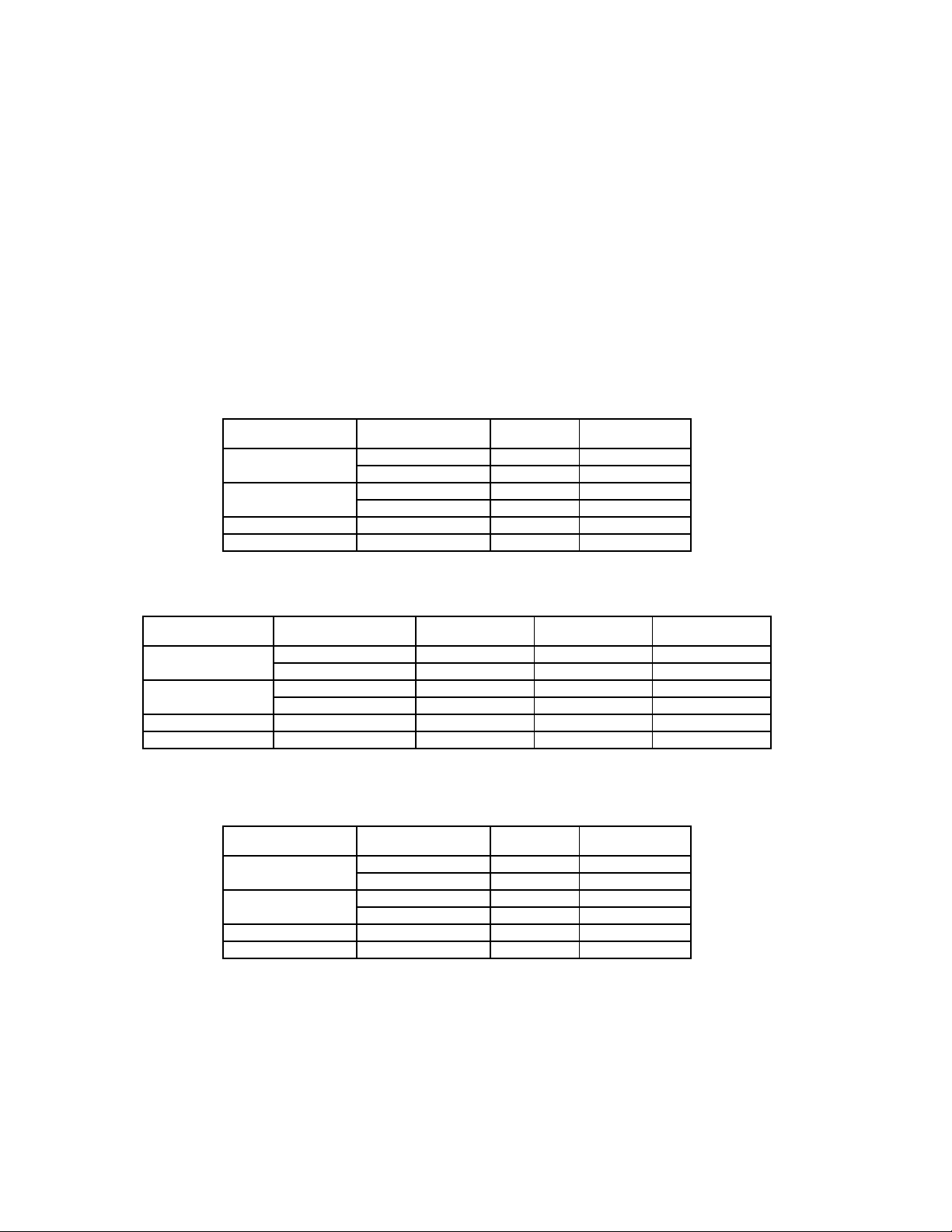
Table 4A — Piston and Charge Combinations — Cooling Only Systems
3. Attach plate with screws under piping hole.
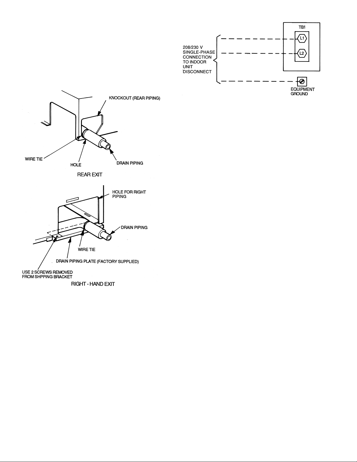
4. Attach drain pipe with nylon wire tie passing through
hole (Fig. 15).
NOTE: Do not fasten nylon wire ties tight enough to
deform the insulation, as this affects its performance.
5. Insulate condensate drain line(s) that are located in
or above an occupied area with a condensate-proof
material such as polyurethane or neoprene.
6. Install an external trap at the end of the condensate
line.
NOTE: Should the installation require one, a
condensate pump may be ordered as a field-installed
accessory.
COOLING
INDOOR UNIT SIZE
024
036
048 048 80 12.2
060 060 90 12.5
OUTDOOR UNIT
538A
018 57 7.0
024 57 7.75
030 65 10.1
036 70 8.9
PISTON
SIZE
CHARGE (lb)
Table 4B — Piston and Charge Combinations — Heat Pump Systems
HEAT PUMP
INDOOR UNIT SIZE
024
036
048 048 82 73 12.2
060 060 —* 80 12.8
*Size 060 indoor heat pump systems use a TXV (thermostatic expansion valve), part no. EA36YD250.
OUTDOOR UNIT
538B
018 49 40 7.5
024 55 43 7.8
030 65 55 12
036 70 63 13
PISTON SIZE
INDOOR
PISTON SIZE
OUTDOOR
CHARGE (lb)
Table 4C — Piston and Charge Combinations — Heat and Cool Systems
HEAT PUMP
INDOOR UNIT SIZE
024
036
048 048 80 12.2
060 060 —* 12.5
*Size 060 indoor heat pump systems use a TXV (thermostatic expansion valve), part no. EA36YD250.
OUTDOOR UNIT
538A
018 57 7.0
024 57 7.75
030 65 10.1
036 70 8.9
PISTON
SIZE
CHARGE (lb)
—8—
Page 9
a40-625
a40-933
Fig. 10 — Mounting Hanging Brackets
MOUNTING
SLOT
Fig. 11 — Hanging Fan Coil Unit
HEX-HEAD
BOLT
a40-531
NOTE: Teflon Seal must face toward the outdoor heat pump unit.
Fig. 13 — AccuRater Metering Device at Service Valve
(Bypass Type Components),
Heat Pump Systems Only
*Factory-supplied.
Fig. 12 — Routing Wires Over Piping
a40-940
—9—
Page 10
VI. STEP 6 — MAKE ELECTRICAL CONNECTIONS
Be sure field wiring complies with local building codes and
NEC, and unit voltage is within limits shown in Table 5.
Contact local power company for correction of improper line
voltage.
WAR NING : To avoid personal injury or damage to
unit, do not make electrical connections until all power
sources are shut down, locked out, and tagged off.
Failure to do so could result in personal injury or unit
damage.
440-14 of NEC. Some codes allow indoor unit to share disconnect with outdoor unit if disconnect can be locked; check
local code before installing in this manner.
1. Route ground and power wires.
WARNING: According to NEC and most local
codes, the unit must have an uninterrupted, unbroken
ground to minimize personal injury if an electric fault
should occur. The ground may consist of electrical wire
or metal conduit when installed in accordance with
existing electrical codes. Failure to follow this warning
could result in an electric shock, fire, or death.
CAUTION: Operation of unit on improper line voltage constitutes abuse and could affect warranty. Refer
to Table 5 for permissible operating limits. Do not
install unit in system where voltage may fluctuate
above or below permissible limits.
NOTE: Use copper wire only between disconnect switch(es)
and unit.
NOTE: Install branch circuit disconnect of adequate size to
handle unit starting current per NEC. Locate disconnect
within sight of, and readily accessible from, unit, per Section
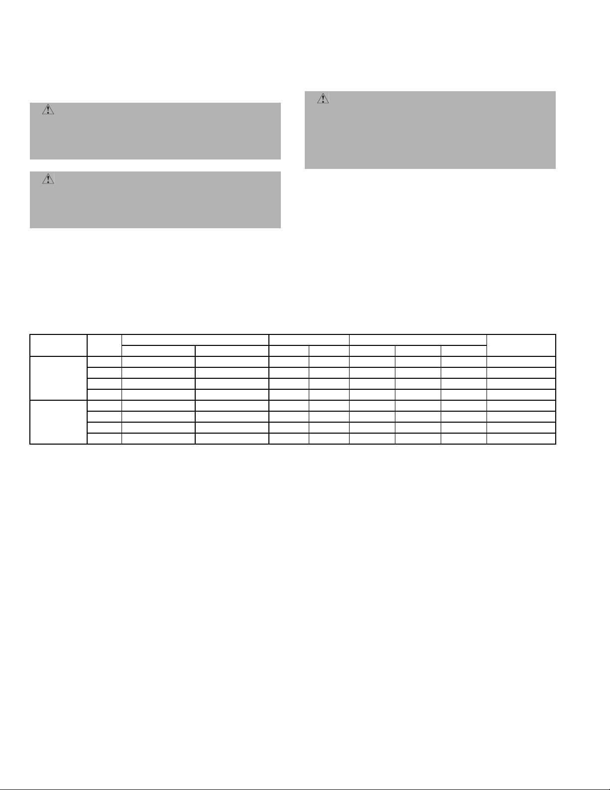
Table 5 — Electrical Data*
SYSTEM
TYPE
COOLING
ONLY
HEAT PUMP
AWG — American Wire Gage
FLA — Full Load Amps
MCA — Minimum Circuit Amps per NEC Section 430-24
MOCP — Maximum Overcurrent Protection
NEC — National Electrical Code
UNIT
SIZE
024† 0.5 — — — 0.53 15 0.50 14
036 1.3 — — — 1.60 15 1.30 14
048 1.1 0.5 — — 2.00 15 1.60 14
060 1.3 1.3 — — 3.30 15 2.60 14
024† 0.5 — 2.00 8.66 9.29 15 9.16 14
036 1.3 — 3.00 13.00 17.70 20 14.30 14
048 1.0 0.5 4.00 17.40 23.80 25 19.00 12
060 1.3 1.3 5.00 21.70 28.70 30 24.30 10
Motor 1 FLA Motor 2 FLA kW FLA MCA MOCP FLA
LEGEND *All units are 208/230-1-60. Minimum operating voltage is 187, maxi-
FAN HEATER POWER
2. Route line power leads (see Fig. 16) from indoor
disconnect to the fan coil unit. Place wire through
hole on the control box (Fig. 17). Connect wire to high
voltage terminal board (TB1) and ground screw.
When routing the wire in the unit, use care to keep
the wire away from refrigerant and condensate
piping and any sharp edges. The 208/230-v units are
factory wired for 230-v to 24-v transformer operation.
For 208-v to 24-v operation, interchange blue (208-v)
and red (230-v) wires. Cap any unused wires with
wire nuts.
MIN WIRE SIZE
(AWG)
mum is 253. Units will operate satisfactorily within this voltage range.
†Electrical data is the same for both the 24,000 Btuh 024 unit and the
024 unit that has been field-reconfigured for 18,000 Btuh. Refer to
Before Installation section on page 3 for reconfiguration details.
—10—
Page 11
a40-1635
LEGEND
φ — Phase
NEC — National Electrical Code
*Standard.
†Accessory item.
**Field supplied.
††Insulate for heat pump application.
Piping
Line Voltage
24 V
Thermistor
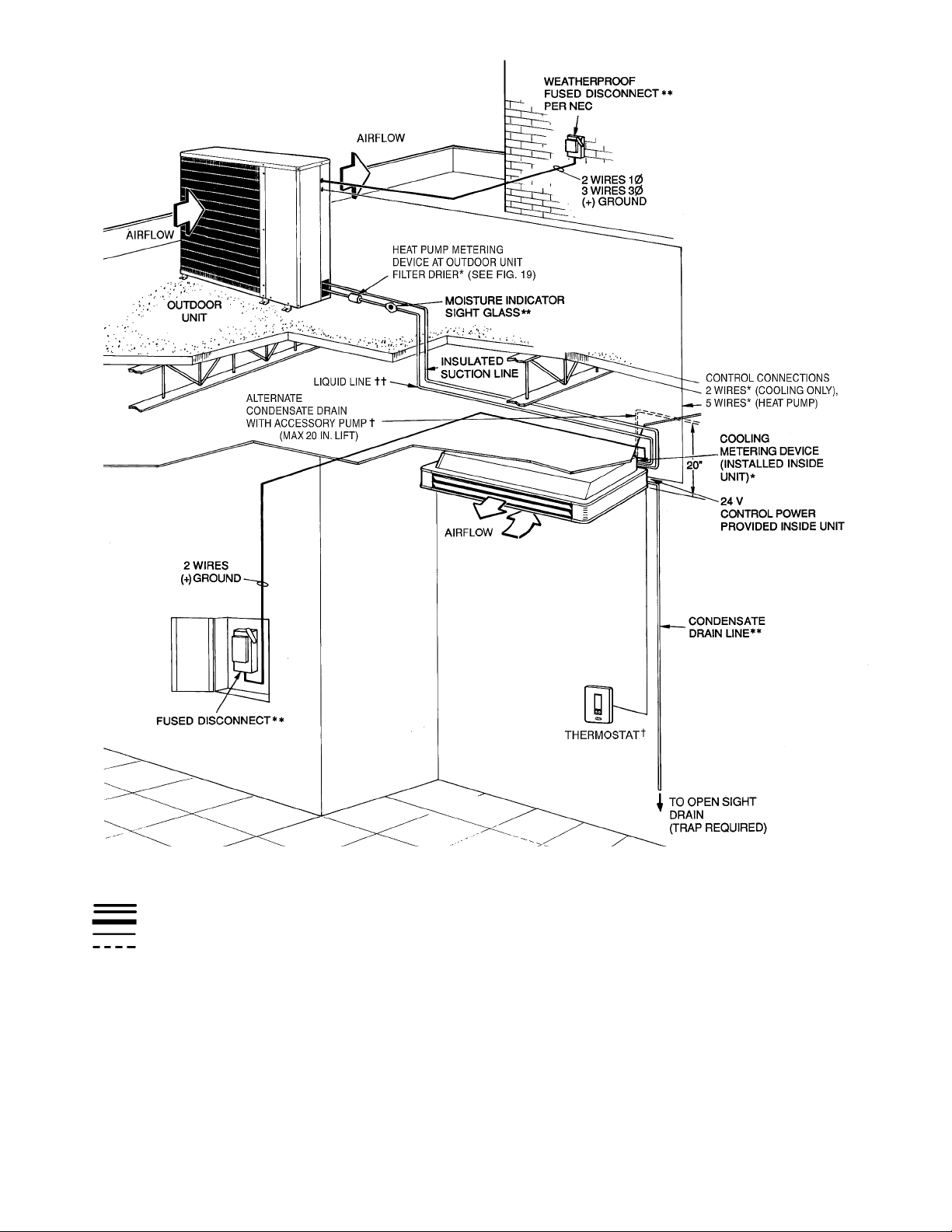
Fig. 14 — Component Location (Typical Ceiling-Suspended System)
NOTES:
1. All piping must follow standard refrigerant piping techniques.
2. All wiring must comply with the applicable local and national codes.
3. Liquid line need not be insulated (cooling only units).
4. Wiring and piping shown are general points-of-connection guides
only and are not intended for a specific installation.
5. Insulate condensate line if run above a conditioned space.
7. Metering device is provided.
—11—
Page 12
VII. STEP 7 — INSTALL THERMOSTAT
These systems use a 3-speed thermostat. The thermostat
monitors the system operation and controls the operating
mode. To change settings or refer to the thermostat Operating Instructions.
Mount thermostat to a wall in the occupied space using 2
field-supplied screws. Locate the thermostat in an area that
is not subjected to drafts or direct sunlight through windows.
Locate thermostat on an interior wall whenever possible.
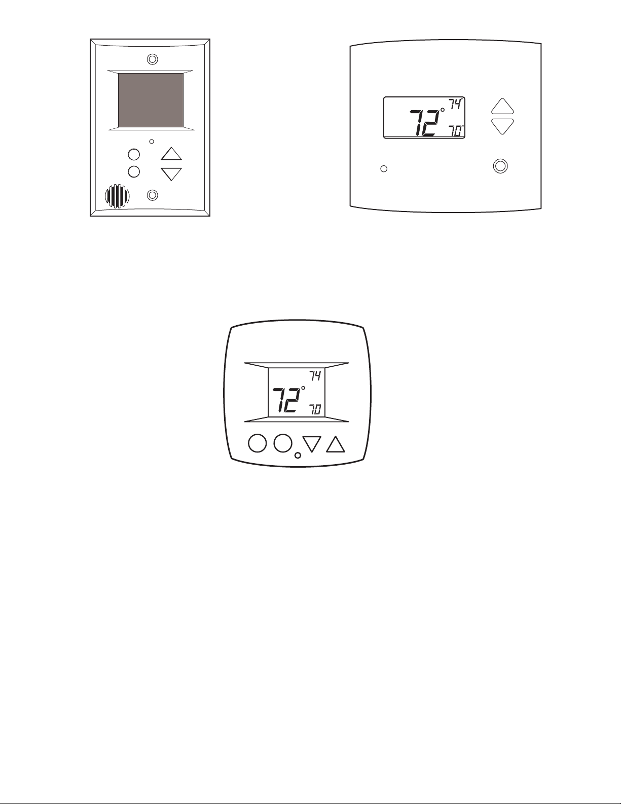
Figure 18 shows available thermostats.
a40-935
LEGEND
TB — Terminal Block
Fig. 16 — Line Power Connections
a40-630
Fig. 15 — Routing Drain Piping
—12—
Page 13
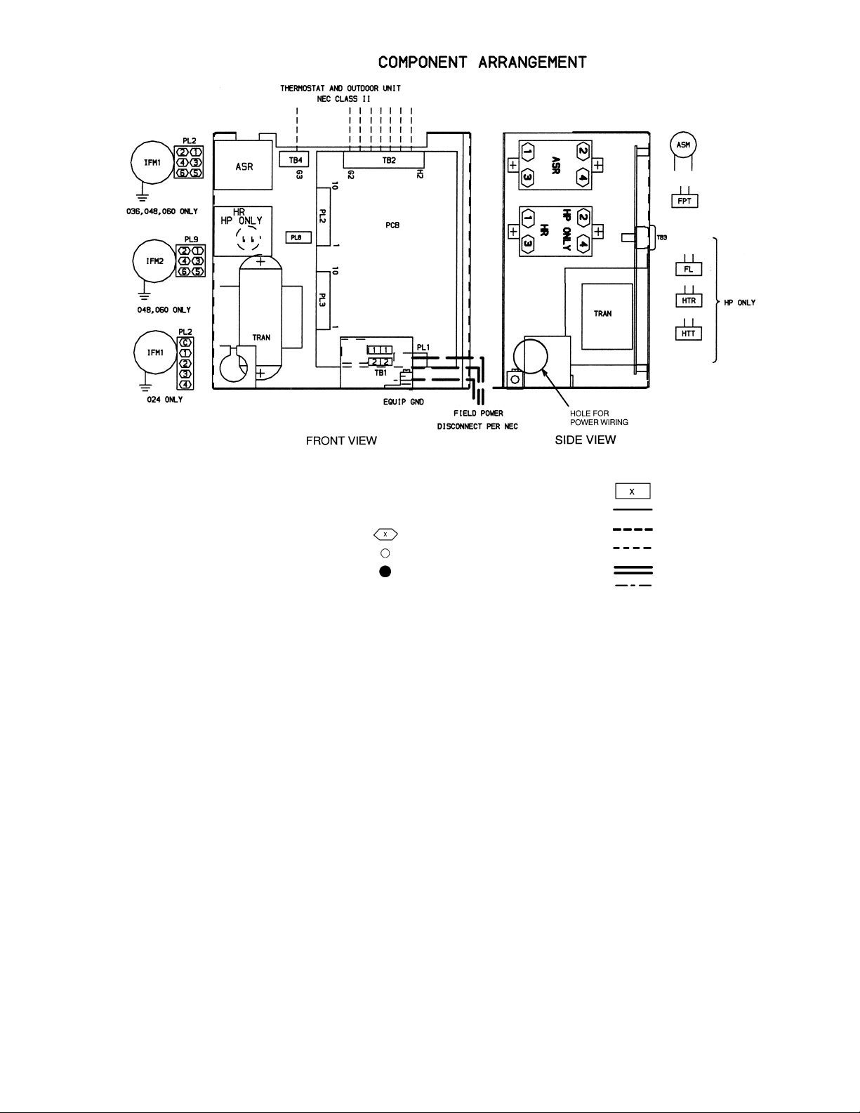
a40-941
LEGEND
ASM — Air Sweep Motor
ASR — Air Sweep Relay
EQUIP GND — Equipment Ground
FL — Fuse Link
FPT — Freeze Protection Thermostat
HP — Heat Pump
HR — Heater Relay
HTR — Heater
HTT — Heater Temp. Thermostat
IFM — Indoor-Fan Motor
NOTES:
1. If any of the original wire furnished must be replaced, it must be replaced with type 90 C wire or its equivalent.
2. Wire in accordance with NEC and local codes.
3. Transformer is thermally protected and will reset automatically.
4. Indoor-fan motor(s) are inherently thermally protected.
NEC — National Electrical Code
PL — Plug
TB — Terminal Board
TRAN — Transformer
Terminal (Marked)
Terminal (Unmarked)
Splice
Fig. 17 — Control Circuit Connections Arrangement
Terminal Block
Factory Wiring
Field Power Wiring
Field Control Wiring
Printed Circuit Board
Accessory or Optional Wiring
—13—
Page 14
AUTO
COOL
HEAT
a40-1384
FLAT THERMOSTAT (FLATSTAT)
COOLING ONLY
HEAT & COOL
(53DFS250-FS-BRY)
a40-1385
a40-1386
COOL
AUTO
HEAT
5-1-1 PROGRAMMABLE THERMOSTAT
COOLING ONLY
HEAT & COOL
(53DFST2-NP-BRY)
Fig. 18 — Thermostats
SLIMLINE THERMOSTAT
HEAT PUMP
COOLING ONLY
HEAT & COOL
(53DFS250-SL-BRY)
—14—
Page 15
VIII. STEP 8 — MAKE CONNECTIONS BETWEEN INDOOR
AND OUTDOOR UNITS
The thermostat is wired between the indoor and outdoor
units to make the system complete.
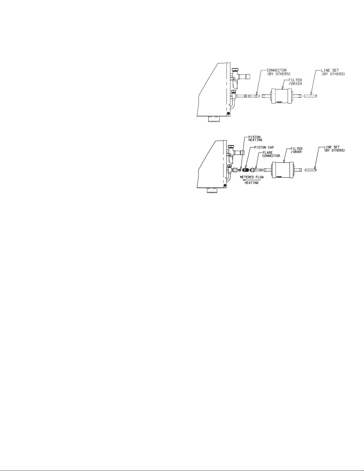
A. Check AccuRater Metering Device
The correct AccuRater (bypass type) refrigerant control is
required for system capacity optimization. An AccuRater
device (see Fig. 19) is supplied with the outdoor unit. Refer to
Tables 4A-4C to determine the correct AccuRater piston size
and charge combination required for the condenser/evaporator
system being installed.
Piston style as shown in Fig. 19 is shipped with the unit. Do
not interchange components between the AccuRater device
types.
B. Cooling Only Systems
The following connections must be made to the outdoor unit
for it to operate as a system with the indoor unit:
Route 2 wires of field-supplied 18-gage AWG (American Wire
Gage) thermostat cable between the low-voltage terminal
block of the fan coil unit and the blue and brown low-voltage
wires in the outdoor unit low voltage terminal block. Connect
the wires Y1 to Y and C to C. See Fig. 20.
C. Heat Pump Systems
The following connections must be made to the outdoor unit
for it to operate as a system with the indoor unit:
Route 5 wires of field-supplied 18-gage AWG thermostat
cable between the low-voltage terminal block of the fan coil
and the outdoor unit low-voltage terminal block. Connect Y1
to Y, R to R, O to O, W2 to W2, and C to C with the wires. See
Fig. 21.
The heat pump unit uses a timed defrost method. The timed
defrost can be field set for 30, 50, or 90 minutes. The timed
defrost is factory set for 90 minutes.
a38-6777
538A018-060
a38-6758
538B018-060
Fig. 19 — AccuRater (Bypass Type)
Metering Device Components
—15—
Page 16
538A
619CNF,CNQ
619CNF,CNQ
538A
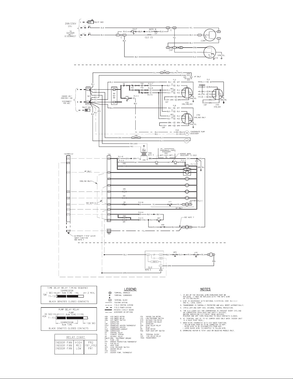
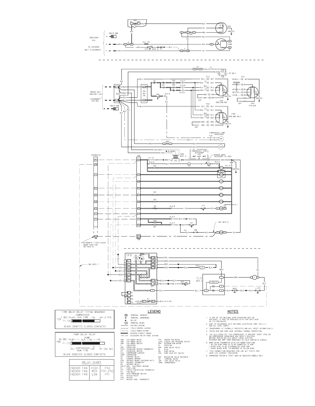
Fig. 20 — Cooling System Wiring Diagram
—16—
a40-1636
Page 17
538B
619CNQ
619CNQ
538B
Fig. 21 — Heat Pump Wiring Diagram
a40-1637
—17—
Page 18
START-UP
WAR NING : Never operate unit without a filter or
with grille removed; damage to the unit or personal
injury may result.
Make the following checks and complete the Start-Up Checklist on page CL-1 before system start-up. Also refer to
the condensing unit Installation, Start-Up and Service
Instructions for system start-up instructions and refrigerant
charging methods.
1. Check condensate drainage system:
a. Remove grille and frame from the unit.
b. On the opposite side of the drain connection,
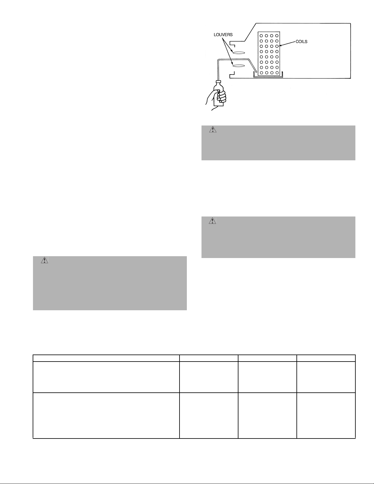
insert a water bottle up into the fan coil unit and
fill drain pan. Refer to Fig. 22. Water must flow
steadily; if not, check the pipe slope or inspect for
any pipe restrictions.
2. Make sure that all wiring connections are correct and
that they are tight.
3. Check that all barriers, covers, and panels are in
place. Ensure that the filters and return-air grilles
have been installed and that the discharge louvers
are positioned correctly.
I. AFTER EXTENDED SHUTDOWN
If the system has been turned off for more than 12 hours and
a crankcase heater is being used, turn on the indoor and
outdoor unit disconnect switches to supply power to the
system for 12 hours BEFORE starting the system.
II. SEASONAL CHANGEOVERS
When changing heat pump system from cooling to heating or
heating to cooling, or before starting cooling only system
after it has been out of use for the winter season, perform the
following steps BEFORE starting the system:
1. Inspect and clean the outdoor unit, particularly the
coil.
2. Clean or replace the air filters in the indoor unit.
3. Clean the indoor unit drain pan and drain pipe, and
remove any obstructions.
4. If the outdoor unit is equipped with a crankcase
heater, turn on indoor and outdoor unit disconnect
switches to supply power to the system 12 hours
before starting the system.
III. ADJUSTING AIRFLOW
A. Automatic Air Sweep
All units are equipped with an air sweep feature which
directs the airflow louvers up and down to provide optimum
room air circulation. The air sweep function can be controlled by the toggle switch located on the lower right corner
of the unit. If using a thermostat with an air sweep switch,
see Fig. 20 and 21 for wiring modifications.
IV. OPERATING MODE MEMORY
After the system is turned off or after a power failure, the
system remains in the last operating mode selected. When
the system is turned back on, or when power is automatically restored, operation continues in the same operating
mode as when the system shut down.
V. AUTOMATIC OPERATION (AUTO.) MODE
If auto. mode is selected, the system automatically switches
over the operating mode from heating to cooling, or from
cooling to heating (heat pump system only) depending on the
selected temperature. Auto. mode also controls fan speed if
not manually overridden.
NOTE: Between the cooling cycle and the heating cycle there
is a neutral zone of approximately 2° F above and 2° F below
the selected temperature when only the fan is operating.
VI. OPERATING SEQUENCE
Ceiling-suspended fan coil units have a relay board which
controls system operation in response to a room thermostat.
The user may manually select any one of 3 fan speeds for
unit operation. Ceiling-suspended systems may be equipped
with an accessory power ventilation kit and/or condensate
pump.
A. Fan Operation
Fan coils are capable of 3-speed operation. See thermostat
instructions for fan speed selection. When the fan(s) is operating in medium or high speed and the unit is equipped with
the power ventilation kit, the ventilation fan will operate to
provide fresh air.
B. Cooling Mode Operation
When the room thermostat senses a demand for cooling, the
fan coil relay board is energized. The indoor fan(s) will start
in the selected speed (if it is not already operating). The
reversing valve (heat pump only) will energize for cooling
operation.
The internal condensate pump (if so equipped) runs whenever the reversing valve is energized (heat pump only) and/
or the unit is in cooling. As long as the condensate float
switch and freeze protection thermostat are closed, the cooling relays in the fan coil unit will close. This energizes the
compressor and outdoor fan in the outdoor unit. The compressor will continue to operate until the room thermostat is
satisfied. When the cooling demand is satisfied, the compressor and outdoor fan will stop. If the system is in the AUTO.
position, the indoor fan will stop with the compressor. If the
unit has the accessory ventilation kit, the ventilation fan will
operate whenever the indoor fan is set for medium or high
speed.
C. Heat Pump Operation
When the room thermostat senses a demand for heating the
indoor fan will start in the selected speed (if not already
operating), and the reversing valve will not be energized.
The internal condensate pump (if supplied) and freeze
protection thermostat are not operated during heating
operation. The control relay (CR2) closes, and the compressor and outdoor fan are energized through the defrost board
(DFB), which is located in the outdoor unit. The microprocessor logic in the DFB is energized when the compressor starts,
and the defrost timer runs. Once every 90 minutes (factory
default setting) of compressor run time, the DFB logic checks
the defrost thermostat (DFT). If the DFT is open, the unit
continues in heating operation. If the DFT is closed, the DFB
switches the unit to defrost mode. The timing on the DFB
may be set at either 30, 50, or 90 minutes.
D. Defrost (Heat Pump Only)
The DFB energizes the RVS (reversing valve solenoid), and
the reversing valve switches to the cooling position. The K1
relay on the DFB opens and the outdoor fan stops. The W2
contact on the DFB is also energized, which in turn
energizes the defrost relay on the fan coil relay board, turns
off the electric heater and stops the indoor fan.
—18—
Page 19
The DFB logic checks the 10-minute defrost timer and the
DFT. If the DFT opens in less than 10 minutes, the DFB
switches the unit back to normal heating operation. If the
DFT remains closed, the DFB switches the unit back to
heating operation after 10 minutes. When the DFB changes
back to heating mode, the RVR (reversing valve relay) is
deenergized and the reversing valve switches back to
heating operation. Both the outdoor and indoor fans come
back on, and if necessary, the electric heater also turns on.
E. System Safeties
The system is equipped with the following safety devices to
protect system components:
Indoor coil freeze protection thermostat — If a coil temperature of 28 F or lower is sensed, the compressor and outdoor
fan will be shut down until the coil temperature exceeds
28 F. The indoor fan will continue to run.
Condensate float switch (units equipped with accessory
condensate pump, cooling cycle only) — If the level of
condensate in the drain pan rises too high, the condensate
float switch will turn the system off.
F. Special Operation, Heating
Outdoor cooling units may be matched with heat pump
ceiling-suspended fan coil units to provide supplemental
electric heat. All other operation is the same as a coolingonly system, except these units have heating capability as
follows:
When the room thermostat initiates a call for heating, the
electric heater is turned on. The indoor unit fan will start at
the same time, if it was not already running.
When the heating requirement is satisfied, the room thermostat will open, and the heater will turn off.
CLEANING AND MAINTENANCE
CAUTION: To avoid the possibility of electric
shock, before performing any cleaning and maintenance operations, always turn off power to the system
by pressing the mode button on the remote thermostat
until the display shows “OFF,” and turning off the outdoor disconnect switch located near the outdoor unit. If
the indoor unit is on a separate switch, be sure to turn
this disconnect off as well.
a40-635
Fig. 22 — Inserting Water into Drain Pan
CAUTION: Do not wash filter in water over 120 F
(to avoid shrinkage). Do not expose filter to fire (to
avoid fire damage). Do not expose filter to direct
sunlight. Clean filter more frequently when air is
extremely dirty.
For proper system operation, perform the cleaning and maintenance operations in Table 6.
I. LUBRICATION
The indoor-fan, automatic air sweep, and the outdoor-fan
motors are factory lubricated and require no oiling.
II. AIR FILTERS (FIG. 23)
CAUTION: Operating the system with dirty air fil-
ters may damage the indoor unit and, in addition, can
cause reduced cooling performance, intermittent system
operation, frost build-up on the indoor coil, and blown
fuses. Inspect and clean or replace the air filters
monthly.
A. Remove Air Filters
Remove filters by pulling them straight out.
B. Clean Or Replace Filters
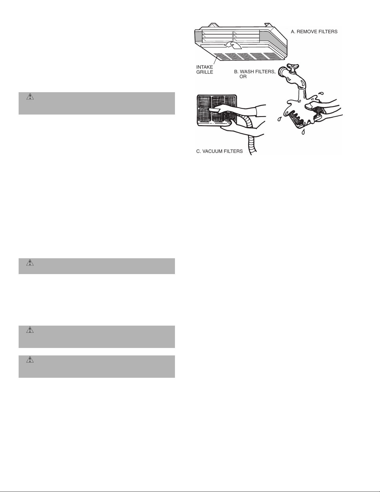
Filters can be vacuumed or washed in warm water. Shake filter to remove any excess water, and replace by sliding filter
behind grille until filter snaps in place. Refer to Fig. 23.
If the filter has begun to break down or is torn, replace it.
Replacement filters are available through your dealer.
Table 6 — Cleaning and Maintenance Schedule
TASK MONTHLY QUARTERLY YEARLY
INDOOR UNIT
Clean Air Filters X
Clean Drain Pipe X
Clean Condensate Drain Pan X
Clean Indoor Coil X
Clean Indoor Unit Front Panel X
OUTDOOR UNIT
Clean the Fins From Outside X
Open the Unit and Clean Fins Inside X
Remove Dust From Electrical Parts X
Check Electrical Connections are Tight X
Clean Outdoor Fan X
Clean Outdoor Coil X
Check that Outdoor Fan Assembly is Tight X
Clean Drain Pan X
NOTE: Maintenance procedures for the outdoor units are in the individual unit installation instructions.
—19—
Page 20
III. CLEAN INDOOR UNIT BOTTOM PANEL
If the bottom panel of the unit becomes dirty or smudged,
wipe the outside of the panel with a soft dry cloth. Use a mild
liquid detergent and wipe off carefully with a dry cloth.
IV. CLEAN INDOOR COIL
To clean the coil, remove indoor unit bottom panel and vacuum the coil fins, using care not to bend or damage fins.
V. CLEAN OUTDOOR COIL (OUTDOOR UNIT)
WAR NING : Some metal parts and sharp fins of
outdoor unit coil can cause personal injury during
cleaning. Clean coil carefully.
To clean the outdoor coil:
1. Remove any dirt or obstruction from discharge
opening.
2. Use a garden hose to spray water on the coil. Debris
that collects between coil fins inhibits heat transfer
— direct the water spray between coil fins to flush
out debris.
VI. CLEAN CONDENSATE DRAINS
Clean all drains and drain pans at the start of each cooling
season. Check the flow by pouring water into the drain.
A. Clean Or Replace Drain Pan
1. Place a plastic sheet on the floor to catch any water
that may spill from drain pan.
2. Remove the intake grille and distribution assembly
(attached).
3. Remove the condensate water in the drain pan by
letting water drain into a 3-gallon bucket.
CAUTION: Do not use a screwdriver to pry drain
pan out of assembly — it could damage the pan.
4. Remove the 4 screws holding the drain pan.
5. Carefully hold the drain pan to remove it from the
assembly.
SERVICE
WAR NING : When servicing unit, turn off all elec-
tric power to unit to avoid shock hazard or injury from
rotating parts.
CAUTION: Do not vent refrigerant to atmosphere
when servicing unit. Recover refrigerant during system repair or unit removal.
I. BEFORE CALLING FOR SERVICE
Save the cost of a service call by doing the following:
1. Be sure main power to system is turned on.
a40-636
Fig. 23 — Cleaning Filters
2. Press Mode button until OFF is displayed. Wait
5 minutes.
3. Press Mode button until either COOL or HEAT is
displayed (as desired).
4. Adjust thermostat set point to desired room temperature. If system starts within a few minutes, service
may not be necessary. If system does not operate
properly, check Table 7 for typical solutions.
A. If System Fails To Operate
Be sure:
• unit ON/OFF switch is in ON position
• fuse or circuit breaker is not tripped
FRESH AIR INSTALLATION OPTION
The units have an installation option, which allows for field
installation of fresh air ventilation. Plan the installation
carefully. Before beginning, measure carefully and follow
acceptable building practices, NEC, and local codes.
I. VENTILATION-AIR ACCESSORY
Refer to ventilation air accessory installation instructions.
TROUBLESHOOTING
If the under-ceiling fan coil unit fails to start or operate properly, sometimes the problem is minor and can be handled
without a service call. Refer to Table 7 for some common
problems, causes, and typical solutions. See Fig. 20 and 21
for additional system troubleshooting details. If the problem
cannot be corrected, contact a local dealer for further
assistance.
—20—
Page 21
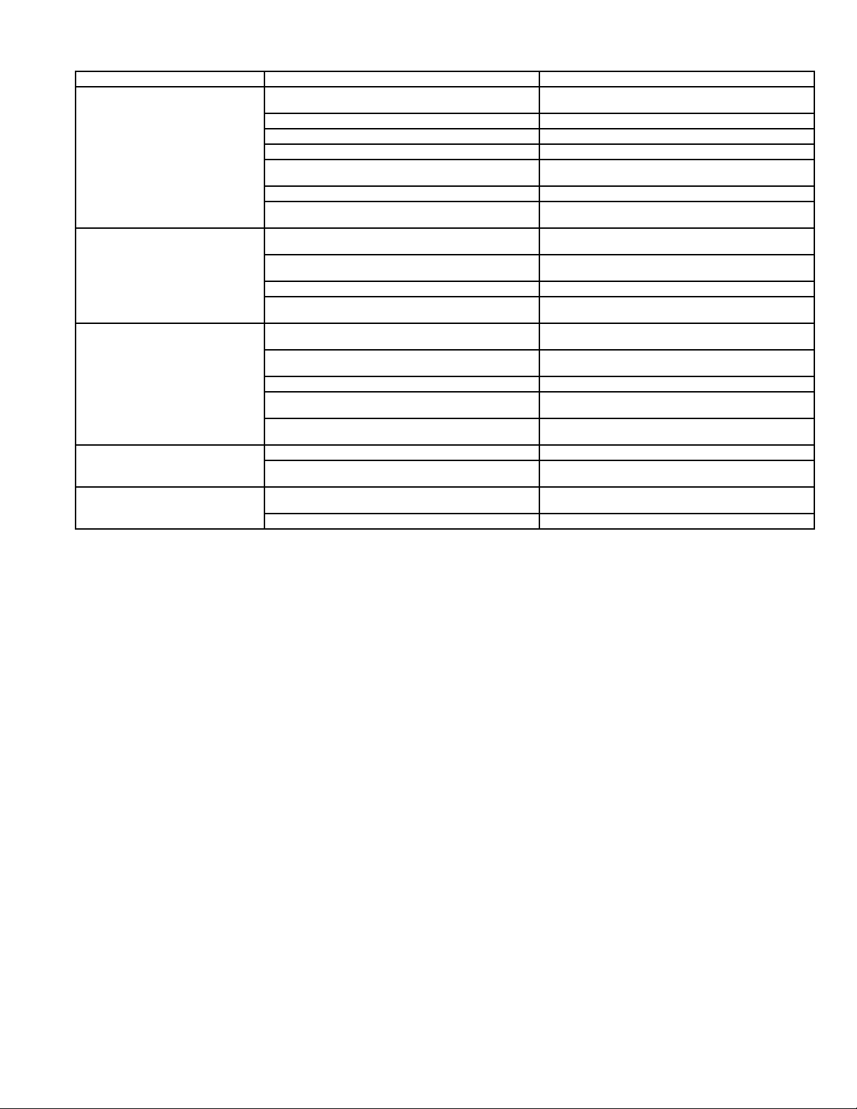
Table 7 — Troubleshooting
PROBLEM CAUSE TYPICAL SOLUTION
System Does Not Start. Blown fuse or circuit breaker tripped at building power
System Does Not Cool Properly. Air filter(s) in indoor unit is dirty or needs to be
System Does not Heat Properly. Air filter(s) in indoor unit is dirty or needs to be
Ice or frost has Formed
on Indoor Coil.†
Insufficient Airflow. Air filter(s) in indoor unit is dirty or needs to be
*If fuse blows or circuit breaker trips again after first start attempt, DO NOT attempt to start system again.
Contact your local dealer for assistance.
†When outdoor temperature is approximately 55 F or below, indoor coil frosting may occur when system is
operated in cooling or maximum dehumidification mode. Units are not intended to operate below 55 F without appropriate accessories.
entry.
Indoor and/or outdoor unit disconnect switch is off. Turn on disconnect switch(es).
Thermostat is set to night mode. Cancel mode using Day/Night button on thermostat.
Power failure. Restore power.
Unit is in off mode. Press Mode button on thermostat until thermostat dis-
Three-minute time delay is running. Wait for 3 minutes.
Temperature is above or below the selected
temperature.
replaced.
Temperature is set too high or too low. Reset temperature to desired comfort setting using
Outdoor unit outdoor coil restricted. Remove obstruction.
Fan speed is set too low. Adjust fan speed to high or auto. using the Fan
replaced.
Temperature is set too high or too low. Reset temperature to desired comfort setting using
Outdoor unit outdoor coil restricted. Remove obstruction.
Fan speed is set too low. Adjust fan speed to high or auto. using the Fan
Outdoor unit outdoor coil is frosted up. Check manual defrost timer setting and adjust as nec-
Low outdoor-air temperature. Run system in fan-only mode until frost is gone.
Air filter(s) in indoor unit is dirty or needs to be
replaced.
replaced.
Fan coil unit coil is blocked. Clean air discharge louvers.
Replace fuse or reset circuit breaker.*
plays the desired unit mode.
Select new temperature using the thermostat.
Clean or replace air filter(s).
the thermostat.
button on the thermostat.
Clean or replace air filter(s).
the thermostat.
button on the thermostat.
essary.
Clean or replace air filter(s).
Clean or replace air filter(s).
—21—
Page 22
SERVICE TRAINING
Packaged Service Training programs are an excellent way to increase your knowledge of the equipment discussed in this manual, including:
• Unit Familiarization • Maintenance
• Installation Overview • Operating Sequence
A large selection of product, theory, and skills programs are available, using popular video-based formats and materials. All include video and/or slides, plus companion book.
Classroom Service Training which includes “hands-on” experience with the products in our labs can
mean increased confidence that really pays dividends in faster troubleshooting and fewer callbacks.
Course descriptions and schedules are in our catalog.
CALL FOR FREE CATALOG 1-800-644-5544
[ ] Packaged Service Training [ ] Classroom Service Training
Copyright 2006 Bryant Heating & Cooling Systems Printed in U.S.A. CATALOG NO. 02-619C0001-II
Page 23

I. PRELIMINARY INFORMATION
START-UP CHECKLIST
OUTDOOR UNIT: MODEL NO. ___________________
INDOOR UNIT: MODEL NO. _____________________
ACCESSORIES: __________________________________________________________________________________
PISTONS: INDOOR SIZE: ____________
OUTDOOR SIZE: ____________
REFRIGERANT PIPING: EQUIVALENT LINE LENGTH: ____________
LIFT: FAN COIL ABOVE OUTDOOR UNIT? ____________
FAN COIL BELOW OUTDOOR UNIT? ____________
II. PRE-START-UP
INDOOR UNIT (REFER TO OUTDOOR UNIT INSTALLATION INSTRUCTIONS FOR OUTDOOR UNIT
PRE-START-UP FUNCTIONS)
IS THERE ANY SHIPPING DAMAGE? ____________
IF YES, WHERE? ____________________________________
WILL THIS DAMAGE PREVENT UNIT START-UP? ____________
IS POWER SUPPLY CORRECT? ____________
HAS GROUND WIRE BEEN CONNECTED? ____________
HAS THE CORRECT SIZE FUSE OR HACR BREAKER BEEN PROVIDED? ____________
ARE POWER WIRES TO THE UNIT SIZED AND INSTALLED PROPERLY? ____________
IS THE DISCONNECT SWITCH INSTALLED WITHIN SIGHT OF THE UNIT? ____________
IS THE LOW-VOLTAGE CABLE (INDOOR TO OUTDOOR UNIT) RUN AND CONNECTED PROPERLY? ____________
HAS CONDENSATE DRAIN BEEN RUN, SLOPED AND TRAPPED PROPERLY? ____________
IS FILTER(S) IN PLACE? ____________
IS UNIT MOUNTED LEVEL? ____________
IS HEATING PISTON INSTALLED (FIG. 13), THE CORRECT SIZE, AND IN THE CORRECT DIRECTION? ____________
III. PIPING
IS A LIQUID LINE SOLENOID INSTALLED IF REQUIRED BY LONG-LINE APPLICATIONS? ____________
IS FILTER DRIER INSTALLED AT THE OUTDOOR UNIT? ____________
HAVE LEAK CHECKS BEEN MADE AT THE COMPRESSOR, OUTDOOR UNIT, FLARE CONNECTIONS, FILTER DRIERS, AND FUSIBLE PLUGS WITH A LEAK DETECTOR?* ____________
*FIELD PIPING AND ALL TUBING CONNECTIONS MUST BE LEAK TESTED BY THE PRESSURE METHOD
DESCRIBED IN GENERAL TRAINING FOR AIR CONDITIONING MANUAL (GTAC2), MODULE 5. USE R-22 AT
APPROXIMATELY 25 PSIG BACKED UP WITH AN INERT GAS TO REACH A TOTAL SYSTEM PRESSURE NOT TO
EXCEED 245 PSIG.
HAS PIPING SYSTEM BEEN EVACUATED TO 1000 MICRONS (IF REQUIRED)? ____________
HAS SYSTEM CHARGE BEEN WEIGHED IN (IF REQUIRED)? ____________
HAVE SERVICE VALVES BEEN FULLY BACKSEATED? ____________
CHECK VOLTAGE: IS VOLTAGE WITHIN RANGE SHOWN FOR UNIT (WITH UNIT OPERATING)?
OUTDOOR ____________ INDOOR ____________
SERIAL NO. ___________________________________
SERIAL NO. ___________________________________
CL-1
Page 24
START-UP CHECKLIST (cont)
IV. START-UP
IF UNIT HAS A CRANKCASE HEATER, HAS IT BEEN ON FOR 24 HOURS? ____________
MEASURE AND RECORD THE:
AIR ENTERING OUTDOOR UNIT: ____________ F
AIR ENTERING INDOOR UNIT: ____________ F
DISCHARGE LINE TEMPERATURE: ____________ F
VAPOR LINE TEMPERATURE: ____________ F
MEASURE AND RECORD THE:
VAPOR LINE PRESSURE: ____________ PSIG
DISCHARGE PRESSURE: ____________ PSIG
START-UP
CHECKLIST
I. PRELIMINARY INFORMATION
THE UNIT SIZED AND IN-
STALLED PROPERLY? IS THE
DISCONNECT SWITCH IN-
STALLED IN SIGHT FROM THE
UNIT?
OUTDOOR UNIT: MODEL NO.SERIAL NO.
INDOOR UNIT: MODEL NO.SERIAL NO.
IS THE LOW-VOLTAGE CABLE (INDOOR TO OUTDOOR UNIT) RUN AND CONNECTED PROPERLY?
ACCESSORIES:
__________________________________________________
________________________________
PISTONS (38HDC and
38QRC SYSTEMS
ONLY): INDOOR SIZE:
OUTDOOR SIZE (38QRC
SYSTEMS ONLY):
REFRIGERANT PIPING: EQUIVALENT LINE LENGTH:
(IF OVER 50 FT)*
LIFT: FAN COIL ABOVE OUTDOOR UNIT (IF OVER 25
FT)*?
FAN COIL BELOW OUTDOOR UNIT (IF OVER
25 FT)*?
*APPLIES ONLY TO 38HDC AND 38QRC UNITS USING
LONG-LINES APPLICATIONS. MAXIMUM EQUIVALENT
LINE LENGTH FOR 38HDS SYSTEMS IS 50 FT. MAXIMUM LIFT ON 38HDS APPLICATIONS IS 30 FT FROM
LOWEST SYSTEM POINT TO HIGHEST SYSTEM
POINT.
CUT ALONG DOTTED LINE
PRE-START-UP
INDOOR UNIT (REFER TO OUTDOOR UNIT INSTALLATION INSTRUCTIONS FOR OUTDOOR UNIT PRESTART-UP FUNCTIONS)
IS THERE ANY SHIPPING DAMAGE?
IF YES, WHERE?
WILL THIS DAMAGE PREVENT UNIT START-UP?
IS POWER SUPPLY CORRECT? (115-V
FOR 40QAB024-048, 115 V UNITS; OR 208/230 V FOR
40QAB024-048, 208/230 V UNITS AND ALL 40QAB060
AND 40QAE024-060 UNITS. ALL SYSTEMS REQUIRE
SINGLE-PHASE POWER)
HAS GROUND WIRE BEEN CONNECTED?
HAS THE CORRECT SIZE FUSE
OR HACR BREAKER BEEN PRO-
VIDED? ARE POWER WIRES TO
Copyright 2006 Bryant Heating & Cooling Systems Printed in U.S.A. CL-2 6-06A CATALOG NO. 02-619C0001-II
CUT ALONG DOTTED LINE
 Loading...