

Page 1

installdt^n, start-up and
service instructions
UNDER CEILING FAN COIL UNITS
619C
Sizes 024-048
2 to 4 Tons
CONTENTS
Page
SAFETY CONSIDERATIONS
INSTALLATION
I. Complete Pre-Installation Checks ..............................2
II. Select Location
III. Mount Unit
IV. Connect Refrigerant Piping
V. Connect Condensate Drain Line
VI. Make Electrical Connections
VII. Install Control................................................................8
VIII. Connections to Outdoor Unit.......................................9
START-UP..............................................................................9-12
I. After Extended Shutdown
II. Seasonal Changeovers
III. Adjusting Airflow
IV. Operating Mode Memory............................................11
V. Automatic Operation (Auto.) Mode
VI. Operating Fault Diagnosis.........................................11
VII. Operation of Microprocessor Control
CLEANING AND MAINTENANCE.......................................12,13
SERVICE..................................................................................14
TROUBLESHOOTING
NOTE: Detailed controls, service, and troubleshooting
......................................................................
.....................................................................
....................................................
.............................................................
.........................................
................................
.......................................
...........................................
................................................
........................................................
.......................
.....................
........................................................
14-17
1
1-9
3
3
3
5
8
9
9
11
11
11
information is in a separate manual, available from your
distributor.
Cancels: New
II 619C-24-1
7/1/92
INSTALLATION
The 619C under ceiling fan coil unit is installed with the 700C
outdoor condensing unit, or the 705C heat pump (Fig. 1). Re
fer to Table 1 to make sure the correct indoor unit is in
stalled with the correct outdoor unit.
Fig. 1 — 619C Under Ceiling Fan Coil Unit
Table 1 — System Combinations for Indoor
and Outdoor Units
SAFETY CONSIDERATIONS
Installing and servicing air conditioning equipment can be
hazardous due to system pressure and electrical compo
nents. Only trained and qualified service personnel should
install or service air conditioning equipment.
Untrained personnel can perform basic maintenance, such as
cleaning and replacing filters. All other operations should be
performed by trained service personnel. When working on air
conditioning equipment, observe precautions in literature, tags,
and labels attached to unit.
Follow all safety codes. Wear safety glasses and work gloves.
Use quenching cloth for brazing operations. Have fire extin
guisher available. Read these instructions thoroughly. Con
sult local building codes and National Electrical Code (NEC)
for special installation requirements.
SPLIT
SYSTEM UNIT UNIT
Under Ceiling Cooling Only System
535BNC024 619CNX0240E0 700CNX024
535BNC036
535BNC048 619CNX0480E0
Under Ceiling Heat Pump System
635ANC024
635ANC036
635ANC048 619CNX0480W0 705CNX048000
INDOOR OUTDOOR
619CNX0360E0
619CNX0240W0
619CNX0360W0
700CNX036
700CNX048
705CNX024000
705CNX036000
Installation instructions for 619C fan coils are contained in
this manual. Refer to this manual for proper installation of
the complete system. Note that the 700C and 705C outdoor
units are shipped with installation and service instructions
for basic installation of the outdoor section.
Be sure the unit will be operated within the application guide
lines shown in Table 2. When installing the 700C or 705C
unit, it is important to note that for cooling operation when,,
the outside air temperature is below 55 F, it is necessary to
equip the outdoor unit with the low-ambient control
accessory.
Page 2

■À
To install this system you will need:
1 — 619C fan coil
1 — 700C or 705C outdoor unit
1 — Remote controller kit (included with 619C fan coil) —
note that kit normally includes 15-ft long wire cable;
however, cable length up to 200 ft can be ordered.
1 — Low Ambient Kit (if required for your application)
1 — Check-Flo-Rater™ Metering Device Kit (included with
619C fan coil)
1 — Fresh-Air Intake Kit (if required for your application)
1 — Condensate Pump Kit (if required for your application)
NOTE: Refrigerant pipe, drain pipe, wire, etc., are also re
quired to install system.
Be sure you have the required parts before beginning instal
lation. The 619C unit utilizes a microprocessor control sys
tem to deliver optimal levels of comfort and efficiency. Be sure
to follow these instructions carefully to obtain proper func
tioning of the unit.
Table 2 - Application Range
COOLING
Maximum
Indoor
95 F DB
71 F WB
Maximum
Indoor
80 F DB
71 F WB
LEGEND
DB — Dry Bulb
WB - Wet Bulb
'Unit may be equipped with a iow-ambient control that will allow
operation down to ~20 F
I. COMPLETE PRE-INSTALLATION CHECKS
A. Unpack Unit
Outdoor Indoor
125 F DB
HEATING
Outdoor Indoor
75 F DB
65 F WB
57 F WB
Minimum
Outdoor
67 F DB
Minimum
55 F DB -20 F DB
55 F DB*
Outdoor
Store unit in the original packaging until it is moved to the
final site for installation. When removing unit from carton,
lift unit by its 4 corners; DO NOT lift unit by its plastic parts.
B. Inspecf^hipmeiit
Upon receipt of shipment check unit for damage. Forward claim
papers directly to the transportation company. Manufac
turer is not responsible for damage incurred in transit.
Check all items; if any item is missing notify your distribu
tor. To prevent loss or damage, leave all parts in original pack
ages until installation.
C. Before Installation
Perform the following steps before installing indoor unit
(Fig. 2). Place the unit upside down on the floor, then:
1. Remove side panels by sliding forward, then away from
sides of unit.
2. Remove air filters from inlet grilles; then remove and
retain screws securing inlet grilles to indoor unit.
3. Remove inlet grilles from indoor unit by sliding
forward.
LOOSEN eOLTS AND SLIDE-
MOUNTING BRACKET THIS
DIRECTION—TO REMOVE
2 T/8
tSSJ
DISCHARGE AIR
SLIDE SIDE PANEL THIS
OIRECTION—TO REMOVE
PIPING JOINT
(LIQUID SIDE)
PIPING JOINT
(VAPOR SIDE)
REMOVABLE AIR FILTER
NOTE: Dimensions shown in brackets [ ] are in mm
Fig. 2 — Removal of Mounting Brackets
from Indoor Unit
'-DRAIN CONNECTION
[INLET AIR
PIPING KNOCKOUT
(RIGHT SIDE)
UNIT 619C
OPERATING WT (lb)
REFRIGERANT
FAN
Rpm
High
Med
Low
Nominal Cfm (High Speed)
COIL
Rows
Face Area (sq ft)
FIns/in.
Number of Circuits
CONNECTIONS
Suction (in.) Flare
Liquid (in.) Flare
Condensate Drain (in.)
LINE SIZES
Suction (in.)
Liquid (in.)
Condensate Drain
Table 3 — Physical Data
NX0240E0 NX0360E0 NX0480E0 NX0240W0
108 117 140
R-22, Check-Flo-Rater Control
1035 1310 1345
990 1160 1307
940 1010 1270
635 935 1300
4 4 4
2.189 2.625 3 069
149 149 14.9
4
%
%
%
%
% % % 3/e
3/4
4
3/4
3/a
3/4
3/4
3/4 3/4
-2-
8 4
3/4 3/a
3/a 3/a
3/4
%
110 119 142
1035
990
940
635
4
2 189 2.625
14.9 14.9
3/4 3/4
Va 3/4
3/4
NX0360W0 NX0480W0
1310 1345
1160 1307
1010
935
4 4
4
3/4
Ve 3/a
3/a 3/a
3/4
1270
1300
3.069
14.9
8
3/4
3/4
%
3/4
Page 3
II. SELECT LOCATION
Consult local building codes and NEC for special installation
requirements.
There are several ways the unit may be installed to different
types of ceiling construction. These instructions do not cover
all installation methods. As a typical installation, these in
structions focus primarily on mounting the unit to metal in
new construction. Plan your installation carefully before you
begin. Listed below are some guidelines that should be fol
lowed when determining location for the unit.
1. Place unit adjacent to an outside wall if fresh air is re
quired, ensuring that location allows for complete air
distribution.
2. Determine a convenient and accessible location to mount
the wired remote controller. Note that because the con
troller is not used to sense room conditions, it is not nec
essary to consider this factor when determining the
controller location.
The controller cable can be routed through walls and does
not need to be surface mounted. For additional informa
tion on remote controller, see separate controller kit in
stallation instructions.
3. Allow sufficient space for airflow clearance, wiring,
refrigerant piping, and servicing unit (Fig. 3).
4. Make sure the unit is easily accessible to electrical power.
5. Run refrigerant piping as directly as possible, avoiding
any unnecessary turns or bends.
6. Condensate piping can be directed through the inside
wall to an approved drain, or directed straight outside.
NOTE: The piping hole for condensate line must slope at a
minimum pitch of 1 in. per 10 ft to ensure proper drainage. If
proper pitch cannot be achieved, install accessory conden
sate pump at this time.
NOTE; The accessory condensate pump should be installed
before hanging the unit.
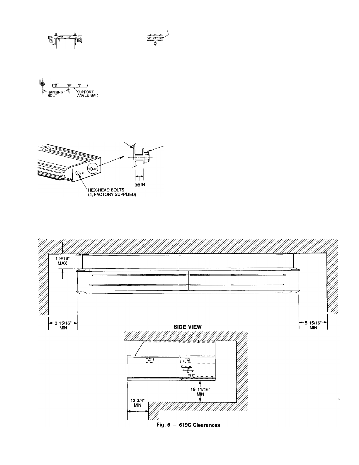
2. Determine installation position, paying particular at
tention to piping lengths and wiring connections, clear
ances, etc. See Fig. 3 for connection locations. Fig. 6 for
clearances, and Fig. 7 and 8 for bolt locations.
3. Open knockout if right-side piping connections are re
quired (Fig. 9).
4. Cut the slit portion in rear of the side panel with a saw
or cutter knife. (Fig. 9).
If indoor unit accessory louver guard is to be installed, in
stall at this time and refer to installation instructions pack
aged with this accessory.
5. Mount hanging brackets on ceiling (Fig. 10) for either
concealed or exposed bolt hanging position.
6. Lift the unit into place, and fit the hex-head bolts on
sides of indoor unit into slit grooves of mounting brack
ets (Fig. 11). Ensure unit is mounted level to assure proper
drainage.
7. Tighten bolts securely.
IV. CONNECT REFRIGERANT PIPING
Fan coil units may be connected to condensing units using
field-supplied refrigerant grade piping. Refer to Table 3 for
the correct size piping. The length of refrigerant pipe de
pends on the unit placement and building structure; keep in
mind to run pipes as directly as possible. For piping require
ments over 50 ft of total run, or more than 25 ft of lift, con
sult the long line application guidelines available from your
distributor.
III. MOUNT UNIT
Refer to Fig. 6 for clearances and dimensions. Use mounting
template included inside box to locate mounting bolt holes,
piping holes, electrical connections, and accessory outdoorair intake, if used.
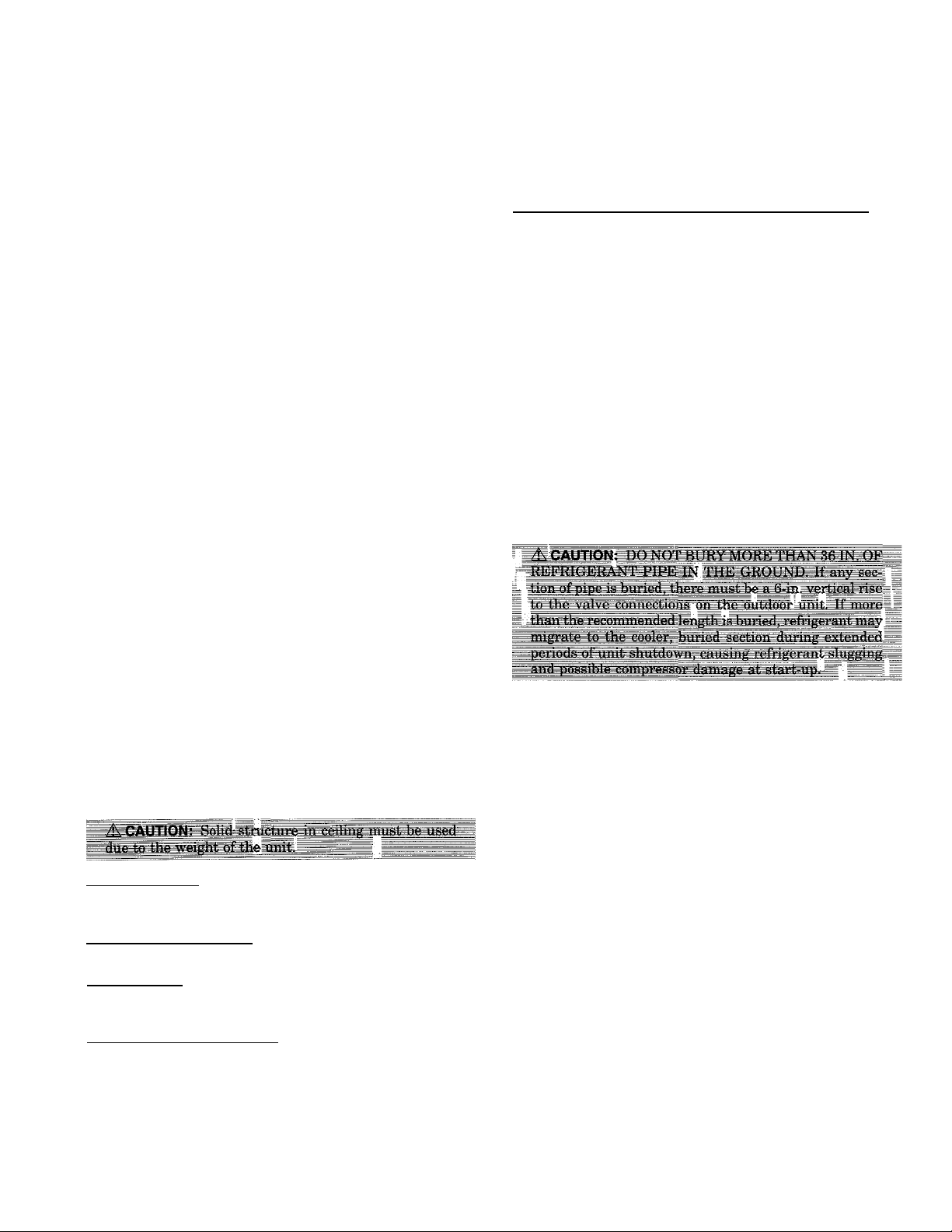
Select proper type of hardware from the guidelines below. See
Fig. 4.
Wooden Structure
Install hanging bolts on a square wooden piece placed over
beams.
Newly Built Concrete Slab
Install hanging bolts with inserts, embedded bolts, etc.
Metal Structure
Install hanging bolts utilizing an existing angle or by install
ing a new support angle.
Previously Built Concrete Slab
Install hanging bolts with expansion anchor.
A. To Mount Unit:
1. Remove mounting bracket and reinstall the 2 hex-head
bolts (factory supplied) into each side of indoor unit as
shown in Fig. 5. Allow approximately 3/8-in. space be
tween bolt head and unit.
Use the following instructions to connect piping.
1. Install insulation. Insulate all refrigerant lines on heat
pumps to prevent condensation. It is extremely impor
tant that all refrigerant lines and the Check-FloRater"' metering device be insulated on heat pumps. On
cooling only units, the liquid line may be left uninsu
lated. Use any acceptable heat resistant closed-cell foam
insulation (minimum 3/8-in. wall thickness). When in
sulating piping, cap ends and slide insulation over the
piping. Insulation can also be cut and placed over
piping.
2. Run liquid and gas refrigerant piping.
a. Run pipes as directly as possible, avoiding any un
necessary turns and bends.
b. Suspend refrigerant pipes so that the insulation is
not damaged and vibrations are not transmitted to
the structure.
c. Leave slack in the refrigerant pipe between the struc
ture and the unit to absorb vibrations.
d. Install flare connection on tubing to liquid line at fan
coil (Fig. 12). The correct piston size is shipped in ths
Check-Flo-Rater body with 619C units. If you have
any questions, use Table 4 to determine required pis
ton size for the system being installed. The arrow on
the metering device body must face away from the
indoor coil.
-3-
Page 4

f8J
9 15/16
f253J I
6 9/16
[167J
-2 II/J6
f69J
UNIT 619C
024
036
048
UNIT 619C
024
036
048
NOTESI
I. OÍMENS/ONS IN [ J ARE MÍLL/METERS.
DIRECT/ON OF AIR FLOW.
DIMENSIONS (in.)
571/2
70/4
E
B
53% evs
665/s
F G
—
—
201/4 371/2
A
5015/16 46
58'3/, 6
713/16
495/8
C
6V8 7%
7%
7%
6%
201/16
2315/16
FRONT VIEW
LOOSEN BOLTS AND SLIDE
MOUNTING BRACKET TH/S
D1RECT10N-»TO REMOVE
SIDE PANEL
D
DISCHARGE AIR
SLIDE SIDE PANEL THIS
DIRECT lON^o-TO REMOVE
PIPING JOINT
(LIQUID SIDE)
PIPING JOINT
REMOVABLE AIR FILTER
Fig. 3 — 619C Dimensional Drawing
-4-
(VAPOR SIDE)
DRAIN CONNECTION
INLET AIR
SIDE VIEW
PIPING KNOCKOUT
(RIGHT SIDE)
Page 5
(SLIDE INSERT)
HANGING I BRACE
BOLT
I WOODEN
WOODEN STRUCTURE
^HANGER BOLT
IL à
METAL STRUCTURE PREVIOUSLY
Fig. 5 - instaliing Hex-Head Mounting Boits
REAM (EDGE SHARP
“ INSERT)
NEWLY BUILT CONCRETE SLAB
Fig. 4 - 619C Unit-Mounting Methods
(Hardware is Fieid Suppiied)
INDOOR UNIT
in 619C Unit
(EMBEDDED BOLT
OF PIPING)
BUILT CONCRETE SLAB
REINFORCING
BAR«
"‘embedded
BOLT
^EXPANSION
ANCHOR
BOLT
e. On heat pump installations check for factory-installed
piston in service valve. If not already installed, in
stall piston in the metering device located in the ser
vice valve on the outdoor unit (Fig. 13). Make sure
Teflon seal on the piston faces toward the outdoor unit.
Use Table 4 to determine required piston size for the
system being installed.
f Refer to 700C and 705C installation, start-up and ser
vice instructions for additional information.
g. Install a liquid line filter drier near the outdoor unit.
On heat pump systems, a bi-flow filter drier must be
used.
3. Insulate and caulk wall openings to reduce air infiltra
tion and refrigerant pipe vibrations on structure.
4. Evacuate piping, if necessary. If either refrigerant pip
ing or the indoor coil is exposed to atmospheric condi
tions for longer than 5 minutes, it must be evacuated to
1000 microns to eliminate contamination and moisture
in the system.
V. CONNECT CONDENSATE DRAIN LINE
Observe all local sanitary codes when installing condensate
drains. Refer to Fig. 3 and 14 for drain hose connection from
indoor unit.
1. Use hard polyvinyl chloride (PVC) pipe material with
nominal ID of 3/4 in. to connect at drain line. Use pipe
insulation 1/4-in. thick, such as Armaflex insulation, on
exposed piping inside the conditioned space.
FRONT VIEW
-5-
Page 6

CONCEALED MOUNTING
HOLE FOR HANGING BOLT
4 -1/2" X 1" SLOTS
EXPOSED MOUNTING
HOLE FOR HANGING BOLT
4 -1/2” X 1" SLOTS
SIDE VIEW OF RIGHTSIDE PANEL
ri-|='C io
T
3 5/8"
IV" !
21
_____1______
i
1-
--------------
UNIT 619C
024
036
048
Fig. 7 — 619C Unit Hanging Dimensions
TOP
11 IN
REAR
NOTE: Dimensions are found in Fig. 7.
Fig. 8 — Mounting Template Included with 619C Unit
B
A
IQ
________
>1
DIMENSIONS (in.)
A
50'5/i6 46
58'3/i6 53%
718/16 66%
B CONCEALED MOUNT -
------
D EXPOSED MOUNT -
23 5/8”
oo
T
IT
r -................................1
1
1
---------------D-----------------
h
---------------A----------------
B C
D
6'/8
6'/8
7% 70V4
49Vb
57V2
POSITION OF
HANGING
BOLT
(3/8 IN DIA.
HOLE)
. FOLD
TEMPLATE
ON DOTTED
LINE
:«i' 1 u-fi
1
-
Fio. 9 — Removina Rear Knockout
If Right-Side Piping Connection is Used
1
rtrr 1
iliC - -------------
CUTTHESUT
PORTION IN REAR
OF PANEL WITH
A SAW OR CUTTER
KNIFE
2. To ensure regular flow of condensate water, the drain
pipe should be pitched toward an open drain or sump at
a downward slope of at least 1/4-in. per foot.
3. Secure drain pipe with nylon wire tie passing through
the knockout, as shown in Fig. 15.
4. Attach plate with screws under piping hole.
5. Attach drain pipe with nylon wire tie passing through
hole (Fig. 15).
NOTE: Do not fasten nylon wire ties tight enough to deform
the insulation, as this affects its performance.
6. Insulate condensate drain line(s). Insulate the conden
sate drain lines that are located in or above an occupied
area with a condensate proof material such as polyure
thane or neoprene.
7. Install an external trap at the end of the condensate line.
NOTE: Should your particular installation require one, a con
densate pump may be ordered as an accessory option.
Fig. 10 — Mounting Ceiling Brackets
Page 7

NOTE: Arrow on Check-Flo-Rater body points in free flow direction away
from the indoor coil
Fig. 12
Check-Flo-Rater™Metering Device in Liquid
Line (Bypass-Type Components)
UNDER CEILING INDOOR UNIT
Fig. 13 - Check-Flo-Rater Metering Device at Service
Valve (Bypass-Type Components)
Air Delivery Louvers
Air Filters
Remote Controller
Not Used
Drain Pipe
Interconnecting Tubing and Wire
Outdoor Condensing Unit
Outdoor Unit Disconnect Switch
Indoor Unit Disconnect Switch
Fig. 14 - Component Location (Typical Under Ceiling System)
OUTDOOR UNIT
-7-
Page 8

RIGHT-HAND EXIT
Fig. 15 — Routing Drain Piping
VI. MAKE ELECTRICAL CONNECTIONS
Be sure field wiring complies with local building codes and
NEC, and unit voltage is within limits shown in Table 5.
Contact local power company for correction of improper line
voltage.
NOTE: Use copper wire only between disconnect switch and
unit.
NOTE; Install branch circuit disconnect of adequate size to
handle unit starting current per NEC. Locate disconnect within
sight from and readily accessible from unit, per Section 440-14
of NEC. Some codes allow indoor unit to share disconnect with
outdoor unit if disconnect can be locked; check local code be
fore installing in this manner.
1. Route ground and power wires.
2. Route line power leads (see Fig. 16) from indoor discon
nect to the fan coil unit. Place wire through hole on the
control box (Fig. 17). Connect wire to high voltage ter
minal board (TB-1) and ground screw. When routing the
wire in the unit, use care to keep the wire away from
refrigerant and condensate piping and any sharp edges.
Units are factory wired for 230 V to 24-V transformer
operation. For 208 V to 24-V operation, interchange blue
(208 V) and red (230 V) wires. Cap unused wires with
wire nuts.
VII. INSTALL CONTROL
The 619C unit is equipped with a microprocessor control which
operates the system. This control is located in the control box
of the fan coil, with thermistors located in the fan coil inlet
and discharge, on the indoor coil, on the outdoor coil, and in
the outdoor-air inlet (heat pump systems only). The ther
mistors monitor system operation and control the operating
mode. To change settings or modes of operation, a wired re
mote controller is supplied.
The factory-preset DIP switches on the 619C control board
set the operation of the unit cooling only or for heat pump
operation. Be sure the switches are set correctly. See wiring
diagram on page 16 or 17, and also the control, service, and
troubleshooting guide (available from your distributor) for more
information.
A. Wired Remote Controller
The wired controller is directly connected to the unit by the
plug connection provided. Standard cable length is 15 ft, but
the cable can be any length up to 200 ft.
Determine where the best location is to mount the controller.
Since the controller is not used to sense the temperature of
the room, locate the controller in a convenient place that is
easily accessible to the user.
The cable can be surface mounted or may be run over ceil
ings and through walls. Follow local codes when installing
low voltage wires.
To install remote controller, see separate remote controller
installation instructions.
OUTDOOR UNIT
700CNX024
700CNX036
700CNX048
705CNX024
705CNX036
705CNX048
LEGEND
B - Chatleff
Table 4 — Required Piston Size for Check-Flo-Rater™ Metering Device
INDOOR UNIT
619CNX0240E0 55
619CNX0360E0
619CNX0480E0
619CNX0240WO 619CNX0360W0
619CNX0480W0
INDOOR PISTON
INDOOR PISTON TYPE
B
65
84
-
-
B
B
B
B
B
'Charge amount is determined with 25 ft. of iine
-8-
OUTDOOR
PISTON
- A
-
-
~ A -
-
-
OUTDOOR PISTON
TYPE
A
A
A -
A
REQUIRED SYSTEM
CHARGE * (lb)
68
6.8
too
-
Page 9

Table 5 — Electrical Data
OPERATIONAL
INDOOR UNIT
619CNX0240E0
619CNX0360E0 20 1.3 160 -
619CNX0480E0 3.7 1.0 396 —
619CNX0240W0 07 0.5 2092
619CNX0360W0 20 1.3
619CNX0480W0
FLA — Full Load Amps
HACR — Heating, Air Conditioning, Refrigeration
LRA — Locked Rotor Amps
MCA — Minimum Circuit Amps per NEC Section 430-24
NEC — National Electrical Code
208/230 VOLT
1-PHASE
CONNECTION
TO INDOOR
DISCONNECT
<
V-PH
208/230-1-60
LEGEND
VOLTAGE*
Max
187
Min
253
FAN
LRA FLA
07 0.5 92
37
WATTS
3160 3
1.0
‘Permissible limits of the voltage range at which unit will operate
satisfactorily.
4396 4
The following checks should be made before system start-up.
Refer to 700C or 705C installation, start-up and service in
structions for system start-up instructions and refrigerant
charging methods.
EQUIPMENT
GROUND
Fig. 16 — Line Power Connections
VIII. CONNECTIONS TO OUTDOOR UNIT
A. Cooling Only Systems
The following connections must be made to the 700C unit for
it to operate as a system with the indoor unit:
1. A thermistor connection cord with a lead length of 35 ft
is shipped with the 619C unit. Run the connection cord
from the condensing unit to the low-voltage terminal strip
on the control board of the fan coil unit. The stripped
end of the connection cord goes to the fan coil end. Use
1. Check condensate drainage system.
a. Remove grille and frame from the unit.
b. On the opposite side of the drain connection, insert a
water bottle up into the fan coil unit and fill drain
pan. Refer to Fig. 18. Water must flow regularly; if
not, check the pipe slope or inspect for any pipe
restrictions.
2. Make sure that all wiring connections are correct and
that they are tight.
3. Check that all barriers, covers, and panels are in place.
Ensure that the filters and return-air grilles have been
installed and that the discharge louvers are positioned
correctly.
care to route the wires so that they will not be dam
aged, and do not run them near power wires. Connect
the orange wires to terminals D1 and D2 on the control
board.
2. Route 2 wires of 18-gage thermostat cable between the
low-voltage terminal block of the fan coil and the 700C
I. AFTER EXTENDED SHUTDOWN
If the system has been turned off for more than 12 hours,
turn on the indoor and outdoor unit disconnect switches to
supply power to the system for 12 hours BEFORE starting
the system.
unit. Connect the wires Y to blue wire going to highpressure switch, and R to R on the low-voltage
transformer.
B. Heat Pump Systems
The following connections must be made to the 705C unit for
it to operate as a system with the indoor unit:
1. A thermistor cord with a lead length of 35 ft is shipped
with the 619C unit. Run this cable from the heat pump
to the low-voltage terminal strip on the control board on
the fan coil unit. Use care to route the wires so that they
will not be damaged, and do not run them near power
wires. Connect the orange wires to terminals D1 and D2
on the terminal strip, and the blue wires to terminals
A1 and A2 on the terminal strip.
2. Route 4 wires of 18-gage thermostat cable between the
II. SEASONAL CHANGEOVERS
When changing heat pump system from cooling to heating or
heating to cooling, or before starting cooling only system af
ter it has been out of use for the winter season, the following
steps must be performed.
BEFORE starting the system:
1. Inspect and clean the outdoor unit, particularly the coil.
2. Clean or replace the air filters in the indoor unit.
3. Clean the indoor unit drain pan and drain pipe, and re
move any obstructions.
4. Turn on indoor and outdoor unit disconnect switches to
supply power to the system 12 hours before starting the
system.
low-voltage terminal block of the fan coil and the 705C
unit low-voltage terminal block. Connect Y to Y, O to O,
G to G, and C to C with the wires.
ELECTRIC
HEATER
kW AT 240 V
-
2
START-UP
20
MAX FUSE OR
HACR TYPE
CKT BKR AMPS
MCA
1 0
1.8
11.5
17.9 35
22.9
15
15
15
20
40
-9-
Page 10

FRONT VIEW
<3>®<Z>(D(B)<3>
I IFM
®®<3>
®®CD
gMHiM5
¿b
QD<S><B>
Itili
i?iat
"T
'B
SIDE VIEW
ll
-POWER
LEADS
CONNECTION
ASM — Air Sweep Motor
ASR — Air Sweep Reiay
CB — Circuit Breaker
DAT — Discharge Air Temperature Thermistor
EQUIP GND — Equipment Ground
IDC — Indoor Coil Temperature Thermistor
IFM — Indoor Fan Motor
NEC — National Electrical Code
PCB — Printed Circuit Board
PL - Plug
RA — Return Air Temperature Thermistor
TB — Terminal Board
TRAN — Transformer
NOTES:
1 If any of the original wire furnished must be replaced, it must be replaced with type 90 C wire or its equivalent.
2 Wire in accordance with NEC and local codes
Fig. 17 — Control Circuit Connections
<Z>
Circuit Board Run
Terminal (Marked)
Terminal Block
Factory Wiring
Field Control Wiring
Field Power Wiring
Accessory or Optional Wiring
-10-
Page 11

III. ADJUSTING AIRFLOW
A. Automatic Air Sweep
All units are equipped with an automatic air sweep feature
which automatically directs the airflow louvers up and down
to provide optimum room air circulation. If the auto sweep
feature is not desired, temporarily start the auto sweep us
ing the remote controller. When the louvers are in the de
sired position, turn the auto sweep off to hold them in that
position.
IV. OPERATING MODE MEMORY
After the system is turned off or after a power failure, the
system remains in the last operating mode selected. When
the system is turned back on, or when power is automati
cally restored, operation continues in the same operating mode
as when it shut down.
V. AUTOMATIC OPERATION (AUTO.) MODE
If Auto, mode is selected, the system automatically switches
over the Operating mode from heating to cooling, or from cool
ing to heating (heat pump system only) depending on the se
lected temperature.
NOTE: Betvieen the cooling cycle and the heating cycle there
is a neutral zone of approximately 2° F above and 2° F below
the selected temperature when only the fan is operating. This
neutral zone lasts for a minimum of 10 minutes.
VI. OPERATING FAULT DIAGNOSIS
The system includes an automatic diagnosis feature which is
activated under difficult or unacceptable operating condi
tions. If such conditions occur, the system stops automati
cally, the operating fault signal appears on the liquid crystal
display (LCD) of the remote controller, and an analysis of the
system operating conditions is initiated. The system will then
be restarted automatically, as soon as normal conditions have
been restored, or it will remain off. If the system does not
start again, the temperature indicator on the LCD display
alternates between the selected temperature value and an er
ror code. See separate controls, service, and troubleshooting
guide to troubleshoot the problem.
VII. OPERATION OF MICROPROCESSOR CONTROL
This system is controlled by a microprocessor control de
signed to give optimum levels of comfort and operating effi
ciency. The control is located in the 619C unit. To operate
the unit, a remote controller is required. This control may be
wired directly to the unit and mounted on the wall up to
200 ft away from the unit.
See separate owner’s manual for remote controller operation
instructions. More detailed operating sequence and timing are
located in the controls, service, and troubleshooting guide. Both
manuals are available from your distributor.
There are 7 operating modes (including the OFF mode) for
cooling only systems and 11 operating modes (including the
OFF mode) for heat pump systems. The following operation
should be expected in each mode.
• OFF Mode — When the unit is in the OFF mode, all func
tions (compressor, outdoor fan, indoor fan, electric heat, and
air sweep) are off, except the reversing valve, which will
stay energized if the unit was last operated in the COOL
ING mode.
• AIR CIRCULATION Mode (Fan Operation Only) - When
AIR CIRCULATION mode is selected, the indoor fan will
operate continuously in the selected speed (high, medium,
low, or auto). If the AUTO, mode is selected, the indoor fan
will operate at high speed. The compressor, outdoor fan,
and electric heat are off The reversing valve will remain
in the last operating mode. The air sweep motor will oper
ate if selected.
• COOLING Mode — When the COOLING mode is selected,
the indoor fan will operate continuously at the selected speed
if the speed is high, medium, or low. If the indoor fan is in
auto., the fan will change operating speeds depending on
the room temperature. The electric heat will be off and re
versing valve will be on. The compressor cannot run for 3
minutes from the time the system starts up or for 3 min
utes from the time it last operated. When the temperature
of the room is 2° F above the selected temperature, the com
pressor and outdoor fan will operate until the room tem
perature is equal to the selected temperature. If the room
temperature is 4° F or more above the selected tempera
ture, the indoor fan will run at high speed. When the room
temperature is between
2° F and 4° F above the selected
temperature, the indoor fan will operate at medium speed.
When the room temperature is 2° F below the selected tem
perature, the indoor fan will operate at low speed.
When the room temperature is equal to the selected tem
perature, the compressor and outdoor fan shut off. The in
door fan, if in auto, operation, operates for one minute af
ter the compressor shuts off. The fan remains off for 3
minutes, then operates for one minute at low speed. The
indoor fan repeats this process until cooling is again
required.
• MAXIMUM DEHUMIDIFICATION Mode - When the DE
HUMIDIFICATION mode is selected, the indoor fan will
operate continuously at the selected speed if the speed is
high, medium, or low. If the indoor fan is in auto, opera
tion, the fan will change operating speeds depending on the
room temperature. The electric heat will be off and revers
ing valve will be on. The compressor cannot run for 3 min
utes from the time the system starts up or for 3 minutes
from the time it last operated.
Initial Operation — When the mode is first selected, or if
the indoor fan has been off for more than one minute, the
fan will operate at low speed for 30 seconds. Then, if the
room temperature is above the selected temperature, the
unit will operate for 16 minutes, and the compressor and
outdoor fan will operate. The indoor fan will operate as in
the cooling mode. After 16 minutes of operation, the unit
switches to normal operation.
If the room temperature is below the selected tempera
ture, the unit will operate for 8 minutes, and the compres
sor and outdoor fan will operate for 3 minutes. The indoor
fan will operate in low speed, and one minute after the com
pressor stops the indoor fan stops. After remaining off for
3 minutes, the indoor fan starts in low speed for one minute,
then switches to normal operation.
-11-
Page 12

Normal Operation — When the temperature of the room is
6° P above the selected temperature, the compressor and
outdoor fan will operate for 8 minutes. The indoor fan will
operate in low speed. If the room temperature is above the
selected temperature, but not by more than 6° F, the com
pressor and outdoor fan operate for 4 minutes. The indoor
fan will run at low speed and will stop 30 seconds after the
compressor stops. After 3 minutes, the indoor fan runs at
low speed for 30 seconds. The normal dehumidification op
eration is repeated for the new room temperature.
When the room temperature is within 4° F below the se
lected temperature, the system operates for 8 minutes. The
compressor and outdoor fan operate for 3V2 minutes. The
indoor fan will operate at low speed and will stop 30 sec
onds after the compressor stops. After 3 minutes, the in
door fan starts in low speed for one minute. The normal
dehumidification operation is repeated for the new room
temperature.
If the room temperature is 4° F below the selected temper
ature, the compressor, outdoor fan, and indoor fan remain
off. After 3 minutes, the indoor fan operates at low speed
for one minute. This is repeated until 8 minutes have elapsed.
The normal dehumidification operation is repeated for the
new room temperature.
HEAT PUMP Heating Mode (Heat Pump Systems Only)
— When the HEAT PUMP mode is selected, the indoor fan
will operate continuously at the selected speed if the speed
is high, medium, or low. If the indoor fan is in auto oper
ation, the fan will change operating speeds depending on
the room temperature. The electric heat is off and the re
versing valve will be on. The compressor cannot run for 3
minutes from the time the system starts up or for 3 min
utes from the time it last operated. When the temperature
of the room is 8° F below the selected temperature, the unit
will operate in HEAT PUMP mode until the temperature
is 2° F above the selected temperature. If the temperature
of the room is between 2° F and 8° F below the selected
temperature, the unit operates in HEAT PUMP mode un
til the selected temperature is reached.
In the HEAT PUMP mode, the compressor and outdoor fan
will operate until the room temperature has reached the
temperature indicated above. The indoor fan will remain
off until the discharge temperature of the fan coil is 86 F.
The fan will then operate in low speed until the discharge
temperature is 98 F. Then the fan will operate at high speed
if the room temperature is 4° F or more below the selected
temperature. The indoor fan will run at medium speed when
the room temperature is between 2° F and
4° F below the
selected temperature. The indoor fan will operate at low
speed if the room temperature is within 2° F of the se
lected temperature. When the heating demand is satisfied,
the compressor and outdoor fan will stop and the indoor
fan will operate until the discharge air temperature is
77 F. The fan will turn off for 3 minutes, then turn on for
one minute — this will be repeated until heating is again
required.
' MAXIMUM HEATING Mode (Heat Pump Systems Only)
— This mode of operation is the same as the HEAT PUMP
heating mode, except that electric heat is used to assist the
heat pump.
• ELECTRIC HEATING Mode (Heat Pump Systems Only)
— The indoor fan operation is the same as the HEAT PUMP
mode, except that electric resistance heating only is used.
• AUTOMATIC OPERATION Mode - AUTOMATIC OPER
ATION mode runs the system in cooling or heating at 2° F
above the selectéd temperature for cooling and 2° F below
the selected temperature for heating. In the temperature
range between heating and cooling, only the fan will oper
ate. A minimum of 10 minutes is required between a change
from heating to cooling or from cooling to heating.
• DEMAND DEFROST Mode (Heat Pump Systems only) —
This unit uses a demand defrost system to remove frost
from the outdoor coil during heating operation. The indoor
fan and outdoor fan are shut off during defrost. For com
plete description of defrost operation, see the controls, ser
vice and troubleshooting guide sections of the duct-free
systems manual, available from your distributor.
• SLEEP Mode — The SLEEP mode timer will turn the unit
off when the timer reaches zero minutes. During the first
IV2 hours from the time the SLEEP mode timer starts, the
room temperature is set back from the selected tempera
ture a total of 4 F in cooling and 6 F in heating.
• AWAKE Mode — The awake timer will turn the unit on
when the timer reaches zero minutes. The unit will start
in the same mode and at the same selected temperature as
when the system shut off.
NOTE: The system can be programmed for the sleep mode
or the awake mode, but it cannot be programmed for both of
these modes simultaneously.
CLEANING AND MAINTENANCE
For proper system operation we recommend that the clean
ing and maintenance operations in Table 6 be performed.
I. LUBRICATION
The indoor-fan motor, automatic air sweep motor, and the
outdoor fan motor are factory lubricated and require no
oiling.
-12-
Page 13

II. TO REMOVE AND CLEAN OR REPLACE AIR FILTERS
(FIG. 21)
A. To Remove Air Filters
Remove filters by pulling them straight out.
B. To Clean or Replace Filters
Filters can be vacuumed, or washed in warm water. See
Fig. 19. Shake filter to remove any excess water, and replace
by sliding filter behind grille until filter snaps in place.
NOTE: After cleaning, be sure to press the Filter Reset but
ton on the mode selection panel of the remote controller.
If the filter has begun to break down or is torn, it needs to be
replaced. Replacement filters are available through your
distributor.
A. REMOVE FILTERS
III. TO CLEAN INDOOR UNIT BOTTOM PANEL
If the bottom panel of the unit becomes dirty or smudged,
wipe the outside of the panel with a soft dry cloth. Use a mild
liquid detergent and wipe off carefully with a dry cloth.
IV. TO CLEAN INDOOR COIL
To clean the coil, remove indoor unit bottom panel and con
densate pan, and then vacuum the coil fins, using care not to
bend or damage fins.
V. TO CLEAN OUTDOOR COIL
To clean the outdoor coil:
1. Remove any dirt or obstruction from discharge opening.
2. Use a garden hose to spray water on the coil. Debris that
collects between coil fins inhibits heat transfer — direct
the water spray between coil fins to flush out debris.
VI. TO CLEAN CONDENSATE DRAIN PIPE AND PAN
Clean drain pipe quarterly and drain pan at the start of each
cooling season. Check the flow by pouring water into the drain
pipe.
A. To Clean or Replace Drain Pan
1. Place a plastic sheet on the floor to catch any water that
may spill from drain pan.
INTAKE
GRILLE B WASH FILTERS,
OR
2. Remove the air intake and distribution assembly.
3. Remove the condensate water in the drain pan by let
ting water drain into a 3-gallon bucket.
4. Remove the 4 screws holding the drain pan.
5. Carefully hold the drain pan to remove it from the
assembly.
C. VACUUM FILTERS
Fig. 19 — Cleaning Filters
Table 6 — Cleaning and Maintenance Schedule
TASK MONTHLY
INDOOR UNIT
Clean Air Filters
Clean Drain Pipe X
Clean Condensate Drain Pan
Clean Indoor Unit Front Panel
OUTDOOR UNIT
Clean the Fins From Outside
Open the Unit and Clean Fins Inside
Remove Dust From Eiectricai Parts
Check Eiectricai Connections are Tight
Ciean Outdoor Fan X
Check that Outdoor Fan Assembiy is Tight
Clean Condensate Drain Pan
NOTE: Maintenance procedures for the outdoor unit are in the 700C and 705C instaiiation instructions
X
QUARTERLY YEARLY
X
X
X
X
X
X
X
X
-13-
Page 14

1
SERVICE
NOTE: Refer to the control, service and troubleshooting guide
sections of the duct-free systems manual for a complete de
scription of the control system and for detailed service and
troubleshooting procedures. This manual is available from your
distributor.
TROUBLESHOOTING
I. DIAGNOSTIC CODES
This unit is equipped with a microprocessor control which con
tinuously monitors the operation of the unit. If an opera
tional fault is detected, a fault code appears on the LCD dis
play of the remote controller. A red LED indicator light, located
on the control board in the control box of the indoor unit, will
emit a flash code which can be used to troubleshoot a system
problem. The control will continue to monitor the unit and, if
thè conditions which cause the fault are cleared, the unit will
return to normal operation. If the fault code is present for 5
cycles of the unit, the unit will be locked out and the alarm
code will be displayed alternately with the temperature on
the remote controller LCD display.
If the LED indicator light continuously flashes on for one sec
ond, then off for one second, the control is functioning prop
erly and no fault is present. A fast flashing LED indicates
that a fault has been detected. Table 7 lists the number of
quick flashes and the associated fault. If the system does not
operate, the remote controller does not display a fault code,
and the LED indicator does not flash, either the power to the
control board is off, or the control board has failed.
Table 7 — System Fault Codes
FAULT
CODE*
E2
E3
E4
E5
E6
E7
E8
E11
E12
‘The fault code is alternately displayed with the temperature on the re
mote controller LCD display
tHeat pump systems only
II. TEST MODES
NO. OF
FLASHES
2
3
4
5
6
7
8
11
12
SYSTEM FAULT
Outdoor Coll Thermistor
Outdoor Air Thermistort
Room Air Thermistor
Indoor Coil Thermistor
Discharge Air Thermistor
Compressor Malfunction
Reversing Valve Malfunctlonf
Electric Heat Malfunction
Outdoor Coil Temperature
The remote controller allows troubleshooting of the system
by running a series of test modes. These tests may be man
ually initiated with the remote controller to test the system
operation:
• Fan Only Test
• Cooling Mode Test
• Dehumidification Test
• Heat Pump Heating Test
• Emergency Heat Test
See separate controls, service, and troubleshooting guide for
additional details on operating test modes.
III. SYSTEM TESTS
System tests listed below are performed continuously by the
microprocessor. If a fault is indicated, then the system al
lows only limited operation until the problem is resolved. If
the problem resolves itself, then the code is cleared and op
eration resumes.
A. Indoor Coil High-Temperature Protection (Heat Pump Sys
tems Only)
If indoor coil temperature is greater than or equal to 145 F
but less than 165 F for one minute or more, the system shuts
down.
B. Outdoor Coil High-Temperature Protection (Cooling or
Dehumidification Mode Only)
If outdoor coil temperature is greater than or equal to 145 F
but less than 165 F for one minute or more, the system shuts
down.
C. Indoor Coil Freeze Protection (Cooling or Dehumidifica
tion Mode Only)
If indoor coil temperature is less than or equal to 28 F but
more than —13 F for 4 minutes and the compressor has run
for 24 continuous minutes, the system shuts down.
D. Thermistor Tests
Each thermistor is tested for high limit out of range (shorted
condition) and low limit out of range (open condition). If the
thermistor is out of range, the fault status indicator comes
on and the LED flashes the appropriate fault code.
E. Compressor Failure
If the System is in COOLING or DEHUMIDIFICATION Mode
— After 2 minutes of operation, if the temperature of the in
door coil is not 2° F less than at the time the call for cool
ing started, then a compressor failure is indicated on the re
mote controller LCD display.
If the System is in HEAT PUMP HEATING Mode - After 2
minutes of operation, if the temperature indicated by the out
door thermistor is not 2° F less than at the time the call for
heating started, then a compressor failure is indicated.
F. Reversing Valve Failure
If the System is in COOLING or DEHUMIDIFICATION Mode
— After 4 minutes of operation, if the temperature at the in
door coil is 2° F more than at the time the call for heating
started, then a reversing valve failure is indicated.
If the System is in HEAT PUMP HEATING Mode — After 4
minutes of operation, if the temperature indicated by tbe in
door coil is not 2° F less than at the time the call for heat
ing started, then a reversing valve failure is indicated.
G. Electric Heater Failure
If, 4 minutes after the heater is energized, the discharge-air
temperature is not 2° F above the return-air temperature, an
electric heater failure is indicated.
H. Filter Dirty Indicator
Indicator (on remote controller LCD display) turns on after
250 hours of indoor fan operation.
-14-
Page 15

NOTES FOR FIG. 20 AND 21
1. Compressor and fan motor are thermally protected.
2. Wire in accordance with National Electrical Code (NEC)
and local codes. If any of the original wire must be re
placed, it must be replaced with type 90 C wire or its
equivalent.
LEGEND FOR FIG. 20 AND 21
ASM
ASR
C
CAP
CB
CH
COMP
DATTH
DTS
EQUIP
GND
FL
HPS
HR
HTR
HTT
_
Air Sweep Motor
—
Air Sweep Reiay
_
Compressor Contactor LPS
—
Capacitor
—
Circuit Breaker
—
Crankcase Heater
—
Compressor
—
Discharge Air Thermistor
—
Discharge Temperature Sensor
—
Equipment Ground
—
Fuse Link
—
High-Pressure Switch
—
Heater Relay
—
Heater
Heater Temperature Thermostat
IDC TH
IFM
OATTH
OCTTH
OFM
OFR
PCB
PL
RA TH
RVS Reversing Valve Solenoid
SC
SR
TB
TDR
TRAN —
3. Use minimum of 60 C wiring for field power wiring.
4. Thermostat is internal to unit. Unit must be controlled
with wired or infrared wireless remote controller.
5. Use copper conductors only.
_
Indoor-Coil Thermistor
—
Indoor-Fan Motor
—
Low-Pressure Switch
—
Outdoor Air Thermistor
—
Outdoor Coil Thermistor
—
Outdoor Fan Motor
Outdoor Fan Relay
—
Printed Circuit Board
—
Plug
—
Return Air Thermistor
—
Start Capacitor
Start Relay
—
Terminal Block
--
Time-Delay Relay
Transformer
<Z>
o
•
1 >■ 1
Circuit Board Run
Terminal Marked
Terminal Unmarked
Splice
Terminal Block
Factory Wiring
Field Control Wiring
Field Power Wiring
Accessory or Optional Wiring
-15-
Page 16

Oi
-OPN-
-ft£D-
-UHT-
-BLK-
WIREO
REMOTE
I
Fig. 20 — Typical System Wiring Schematic; Heat Pump Systems
Page 17

I
J
K-0^0-BLK*-BH>^^
- - - - - - -- - - -- - -- - - -•- - - - - - - -
-O-
O j .
LPS
-C0O
Fig. 21 - Typical System Wiring Schematic; Cooling Only Systems
J
 Loading...