

Page 1
IMPORTANT — READ BEFORE INSTALLING
1. Read and become familiar with these installation
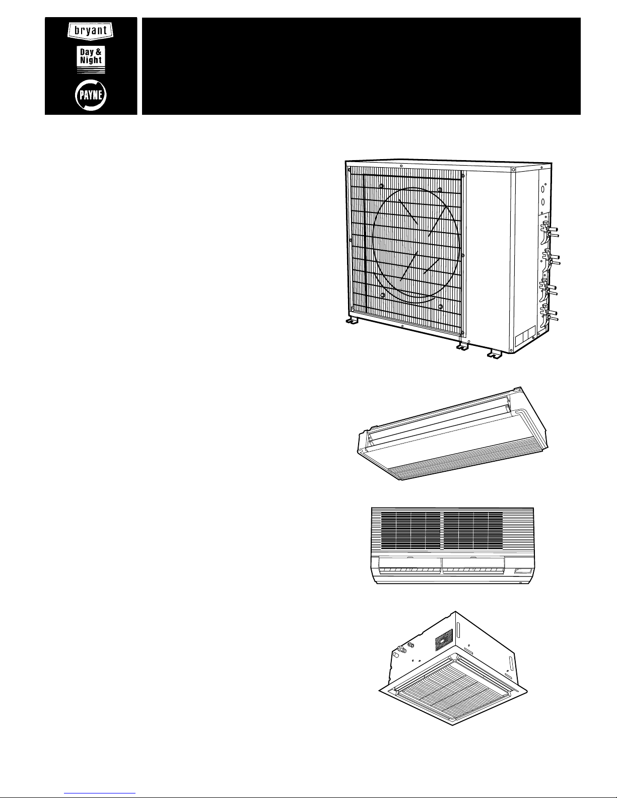
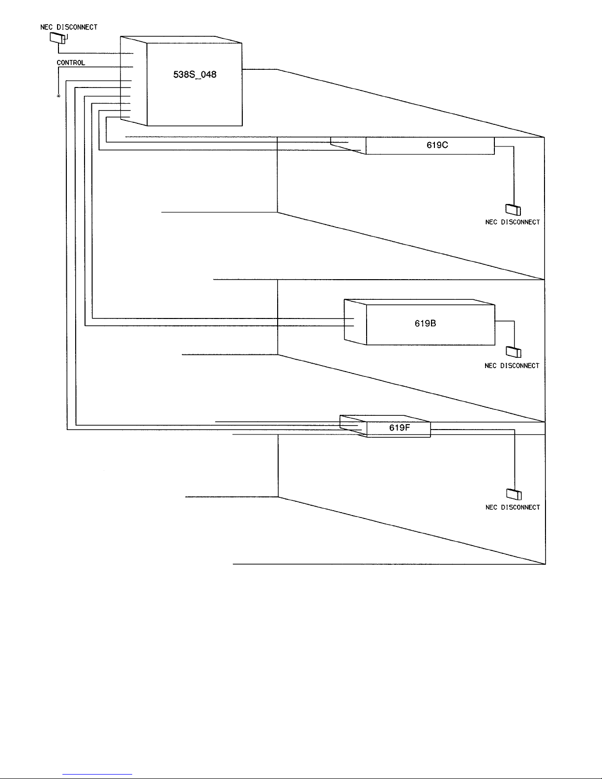
instructions before installingthisunit (see Fig. 1 for typical multi-split system components).
2. Be sure the installation conforms to all applicable local
and national codes.
3. These instructions contain important information for the
proper maintenance and repair of this equipment. Retain these instructions for future use.
CONTENTS
Page
SAFETY CONSIDERATIONS ........................2
GENERAL .......................................2
I. System Description .........................2
II. Planning the System ........................2
INSTALLATION .................................2-13
I. Complete Pre-Installation Checks .............2
II. Install Outdoor Unit .........................4
III. Install Fan Coil Units ........................4
IV. Complete Refrigerant Piping ..................7
V. Make Electrical Connections .................8
START-UP ....................................13,14
I. Leak Test .................................13
II. Evacuate and Dehydrate ....................13
III. Charge System ............................13
IV. Preliminary Checks ........................13
V. Operating Sequence .......................13
SERVICE .....................................15-17
I. Outdoor Fan ..............................15
II. Scroll Compressors ........................15
III. High-Pressure Relief Valve ..................15
IV. Internal Current and Temperature Sensitive
Overload .................................15
V. High-Pressure Switch ......................15
VI. Low-Pressure Switch .......................15
VII. Service Valves ............................15
VIII. Refrigerant Charging .......................16
IX. Compressor Lockout Switch (CLO) ...........16
X. Outdoor-Coil Temperature Thermistor
(OCH TH) .................................17
XI. Low-Ambient Control Thermistor (LAT) .......17
XII. Pressure Transducer .......................17
MAINTENANCE .................................17
I. Lubrication ...............................17
II. Cleaning Coils ............................17
TROUBLESHOOTING ...........................17,18
I. Checking Cooling Control Operation ..........17
START-UP CHECKLIST ...................CL-1 to CL-4
538S (048 Shown)
619C
619B
619F
Fig. 1 — Multi-Split System Components
installation, start-up and
service instructions
MULTI-SPLIT, DUCT-FREE
OUTDOOR COOLING UNITS
538S
Sizes 024,048
2 and 4 Tons
Cancels: New II 538S-24-1
2/15/96
Page 2

SAFETY CONSIDERATIONS
Installing and servicing air-conditioning equipment can be hazardous due to system pressure and electrical components. Only
trained and qualified service personnel should install or service air-conditioning equipment.
Recognize safety information. This is the safety-alertsymbol
( ). When you see this symbol on the unit and in instructions or manuals, be alert to the potential for personal
injury.
Understand the signal words — DANGER, WARNING, and
CAUTION. These words are used with the safety-alert symbol. Danger identifies the most serious hazards which will
result in severe personal injury or death. Warning indicates
a situation that could result in personal injury. Caution is
used to identify unsafe practices which would result in minor
personal injury or product and property damage.
Untrained personnel can perform basic maintenance, such as
cleaning and replacing filters.All other operations should be
performed by trained service personnel. When working on airconditioning equipment, observe safety precautions in literature, and tags and labels attached to unit.
Follow all safety codes. Wear safety glasses and work gloves.
Use quenching cloth for brazing operations. Have fire extinguisher available. Read these instructions thoroughly. Consult local building codes and National Electrical Code (NEC)
Standard ANSI/NFPA 70 (American National Standards
Institute/National Fire Protection Association) for special installation requirements.
WARNING:
Before installing or servicing system, always turn off main power to system. There may be more
than one disconnect switch, since each fan coil unit will
normally have its own disconnect. Turn off accessory
heater power if applicable. Electrical shock can cause
personal injury.
GENERAL
IMPORTANT: Before installing a multi-split system, care-
fully read the following information:
• The TXV (thermostatic expansion valve) is located in the
outdoor unit, NOT the indoor fan coil units.
• The 538S outdoor unit has a factory-installed low-ambient
control which permits unit operation down to 0°F outdoor
ambient temperatures.
• BOTH refrigerant linesbetween the indoor and outdoor units
MUST BE insulated, because the TXV is in the outdoor
unit.
• If the installation includes a 619C ceiling-suspended fan
coil unit, REMOVE the AccuRatert device.
• DO NOT install a filter drier in the line set to the fan coil
units. A filter drier has already been factory-installed on
the outdoor unit.
• DO NOT run thermistor wires and control wires in the same
jacket.
• The 538S unit has been pre-charged at the factory with
sufficient refrigerant forthe entire system (assuming 25ft
of tubing and the use of one of the system combinations
listed in Planning the System section on this page).
I. SYSTEM DESCRIPTION
The 538S multi-split air conditioning system requires 3 major components (see Fig. 1):
• A 538S outdoor condensing unit
• Either 2, 3, or 4 duct-free split fan coil units for distribution of air to a maximum of 4 independent zones (see Planning the System section on this page)
• A wired or wireless infrared remote controller to control
each fan coil unit independently (one remote controller is
necessary for each fan coil unit)
NOTE: The remote controller is not available for 619F inceiling cassette fan coil units.
IMPORTANT: The 538S outdoor units may only be usedwith
the indoor fan coil unit sizes listed in Planning the System
section below. DO NOT try to substitute oradd more fan
coils to these systems.
II. PLANNING THE SYSTEM
This is a complex system with up to 4 separate tubing systems and 8 different control cable sets. Plan the installation
carefully as instructed below.Read these installation instructions (outdoor condensing unit) and the installation instructions included with each fan coil unit carefully and completely
PRIOR to system installation.
1. Maximum line length is 50 ft equivalent (any single line
run), and maximum elevation differential is 30 ft (from
highest to lowest system component).
2. Verify that components received form a legitimate multisplit system as follows:
a. Systems using one 538S_024 outdoor condensing unit
may use any combination (for a system total of 2 fan
coil units) of nominal 1
1
⁄2ton fan coil units.
b. Systems using one 538S_048 outdoor condensing unit
may use any of the following combinations:
• any combination (for a total of 2 fan coil units) of
nominal 2 ton fan coil units (1 fan coil unit per
circuit).
• any one nominal 2-ton fan coil unit on one circuit,
and any combination of 2 nominal 1
1
⁄2ton fan coil
units (for a system total of 3 fan coil units) on the
other circuit.
• any combination (for a system total of 4 fan coil
units) of nominal 1
1
⁄2ton fan coil units (2 fan coil
units per circuit).
3. Identify and record each fan coil section as it will be connected to the 538S outdoor unit on the Multi-Split
Installation Planning Worksheetincluded as part of the
Start-Up Checklist on page CL-1.
4. Check all system components to ensure that all required materials are on hand before starting installation of this system.
5. Re-read Installation section Step III — Install Fan Coil
Units, on page 4 before installing indoor fan coil units.
INSTALLATION
I. COMPLETE PRE-INSTALLATION CHECKS
A. Unpack Outdoor Unit (see Fig. 1)
Move 538S unit to final location. Remove carton from unit,
being careful not to damage service valves and grilles.
B. Inspect Shipment
File claim with shipping company if shipment is damaged or
incomplete. Check unit nameplate to be sure unit matches
job requirements.
C. Consider System Requirements
Consult local building codes and NEC for specialinstallation
requirements.
Allow sufficient space for airflow, wiring, refrigerant piping,
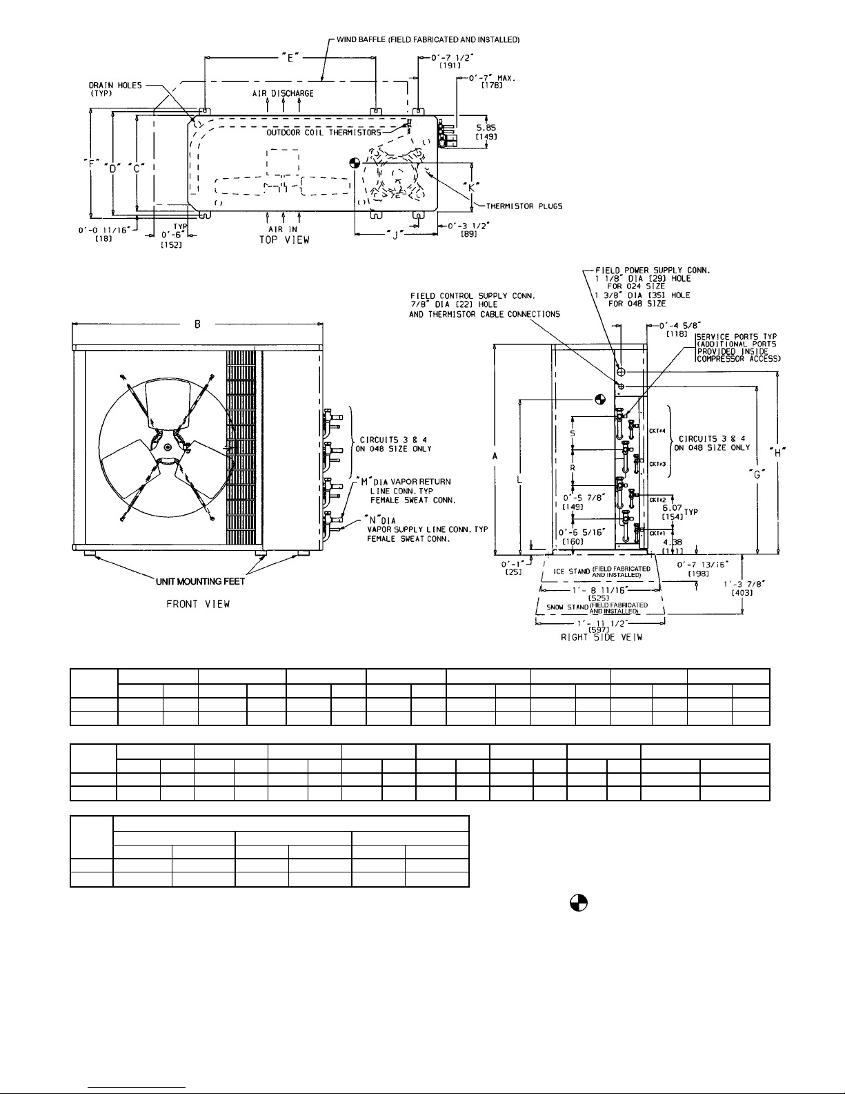
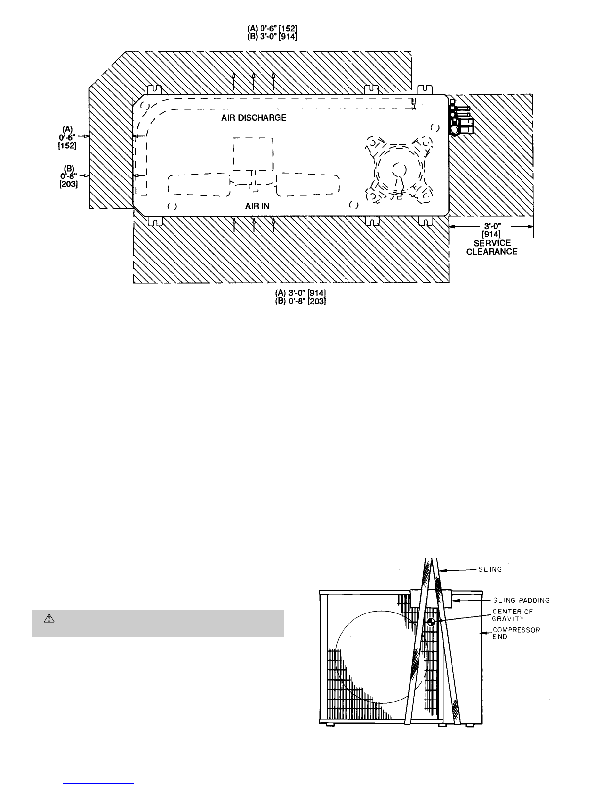
and servicing unit. See Fig. 2 and 3.
Locate unit so that condenser coil airflow is unrestricted on
both sides. Refer to Fig. 2 and 3.
—2—
Page 3
UNIT
538S
_
ABCDEFGH
Ft-in. mm Ft-in. mm Ft-in. mm Ft-in. mm Ft-in. mm Ft-in. mm Ft-in. mm Ft-in. mm
024 2-1
1
⁄8638 3-015⁄
16
938 1-29⁄16370 1-4 406 1-117⁄16595 1-53⁄16437 1-51⁄2445 1-81⁄8511
048 3-1
3
⁄16945 3-89⁄
16
1132 1-51⁄16433 1-67⁄16468 2-61⁄
2
775 1-75⁄8499 2-55⁄8753 2-83⁄16818
UNIT
538S
_
J K L M N R S OPERATING WEIGHT
Ft-in. mm Ft-in. mm Ft-in. mm Ft-in. mm Ft-in. mm Ft-in. mm Ft-in. mm Lb Kg
024 1-2
7
⁄16367 0-63⁄4171 1-0 305 0-05⁄816 0-03⁄810 — — — — 159 72.0
048 1-2
3
⁄4375 0-71⁄2191 1-6 457 0-05⁄816 0-03⁄810 0-65⁄16160 0-57⁄8149 292 132.3
UNIT
538S
_
MINIMUM MOUNTING PAD DIMENSIONS
SUPPORT FEET SNOW STAND ICE STAND
Ft-in. mm Ft-in. mm Ft-in. mm
024 1-11 x 3-6 584 x 1067 2-2 x 3-6 660 x 1067 2-2 x 3-6 660 x 1067
048 2- 0 x 4-2 610 x 1270 2-4 x 4-4 711 x 1270 2-2 x 4-2 660 x 1270
NOTES:
1. Required clearances: with coil facing wall; allow 6 in. minimum clearance on coil side and coil end, and 3 ft minimum clearance on compressor end and fan side. With fan facing wall; allow 8 in. minimum
clearance on fan side and coil end, and 3 ft minimum clearance on
compressor end and coil side. With multi-unit application: arrange
units so discharge of one does not enter inlet of another.
2. Dimensions in [ ] are in millimeters.
3. Center of gravity .
4. Thermistors are used with 619B and 619C fan coils only.
Fig. 2 — Base Unit Dimensional Drawing
—3—
Page 4
Unit may be mounted on a level pad directly on base legs or
mounted on raised pads at support points. See Fig. 2 and 4
for center of gravity.
II. INSTALL OUTDOOR UNIT
A. Mounting on Ground
Mount unit on a solid, level concrete pad. Position unit so
water or ice from roof does not fall directly onto unit. If conditions or local codes require unit be fastened to pad, 6 fieldsupplied tiedown bolts should be used and fastened through
slots provided in unit mounting feet. See Fig. 2.
B. Mounting on Roof
Mount unit on a level platform or frame at least 6 in.
(154 mm) above roof surface. Isolate unit and tubing from
structure.
C. Surrounding Fences and Walls
Select and install surrounding fences and walls to allow for
free entry of ambient air. Avoid pits and solid walls as unit
surroundings, because recirculation of warm discharge air can
occur.
D. Rigging
CAUTION:
Be sure unit panels are securely in place
prior to rigging.
Keep unit upright. Lift unit using sling. Use cardboard or padding under sling, and use spreader bars to prevent sling damage to unit. See Fig. 4. See Fig. 2 and 4 for center of gravity
reference. Install unit so that coil does not face into prevailing winds. If this is not possible and constant winds above
25 mph are expected, field fabricate and install wind baffles.
In areas where outdoor ambient will be less than 40 F during
cooling, wind baffles are also required. Contact your local representative for drawings and assembly details.
III. INSTALL FAN COIL UNITS
Refer to Installation, Start-Up and Service Instructions provided with the fan coil units.
NOTE: If this system is mixing 2 or more types of fan coil
units, be sure to follow instructions provided with each type
of fan coil unit closely.
Mount fan coil units in locations which will be easily accessible when routing refrigerant tubing (see Fig. 5 and 6) and
electrical wiring between the fan coil unitsand outdoor unit.
Fan coil unit locations must also provide adequate drainage
capabilities. If desired, condensate pumps may be used with
any type of fan coil unit.
IMPORTANT: DO NOT install filter driers or AccuRatert re-
frigerant metering device body or pistons into this system.
TXVs are located in the outdoor condensing unit to control
refrigerant flow.
Fig. 4 — Lifting Unit With Sling
NOTE: Dimensions in [ ] are in mm.
(A) Minimum operating clearance required when this side faces a wall.
(B) Minimum operating clearance required when this side faces away from a wall.
Fig. 3 — Operating and Service Clearance
—4—
Page 5
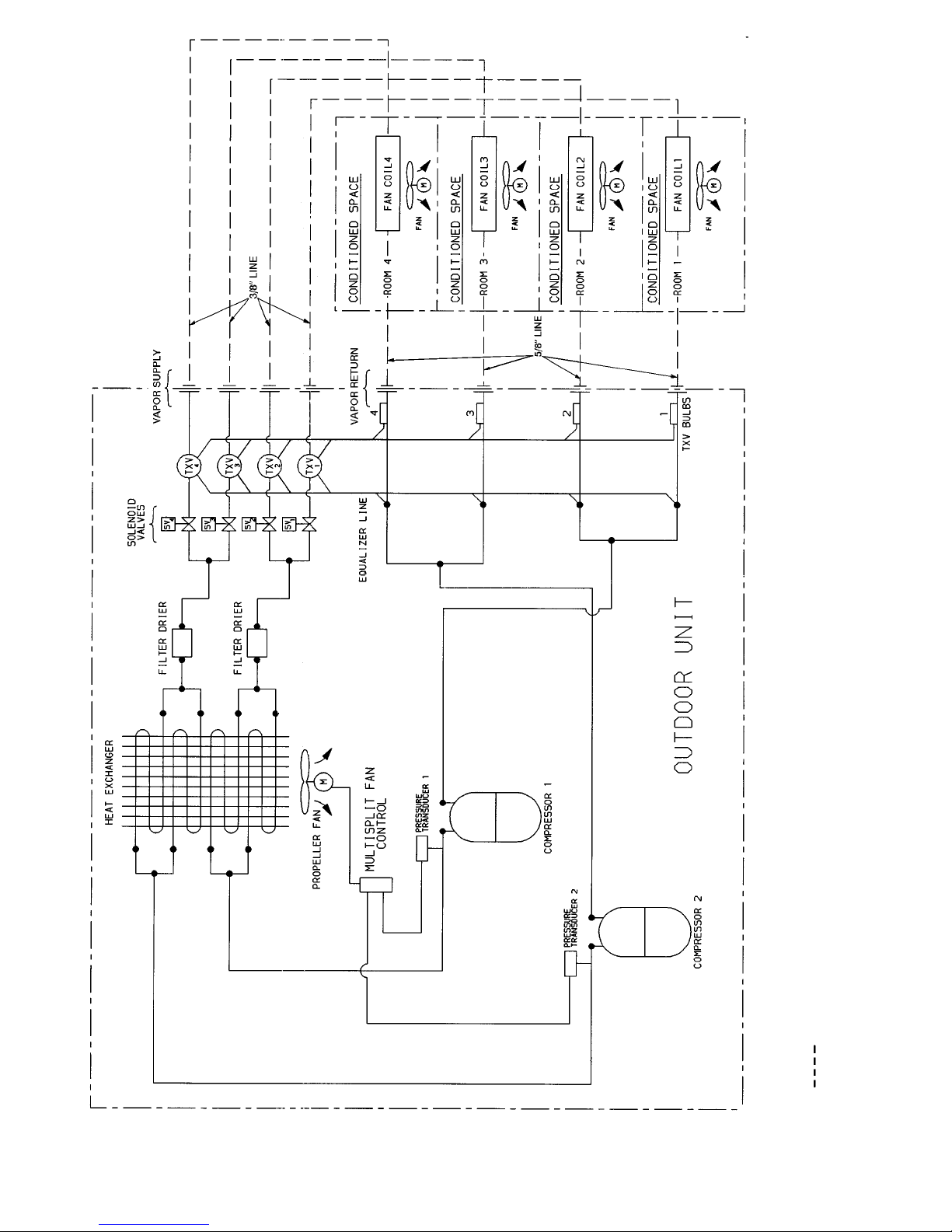
LEGEND
M—Motor
TXV — Thermostatic Expansion Valve
Field-Supplied Tubing
NOTE: Insulate ALL lines between outdoor condensing unit and indoor fan coil units.
Fig. 5 — Refrigerant Tubing Schematic (538S
_
048 Shown)
—5—
Page 6
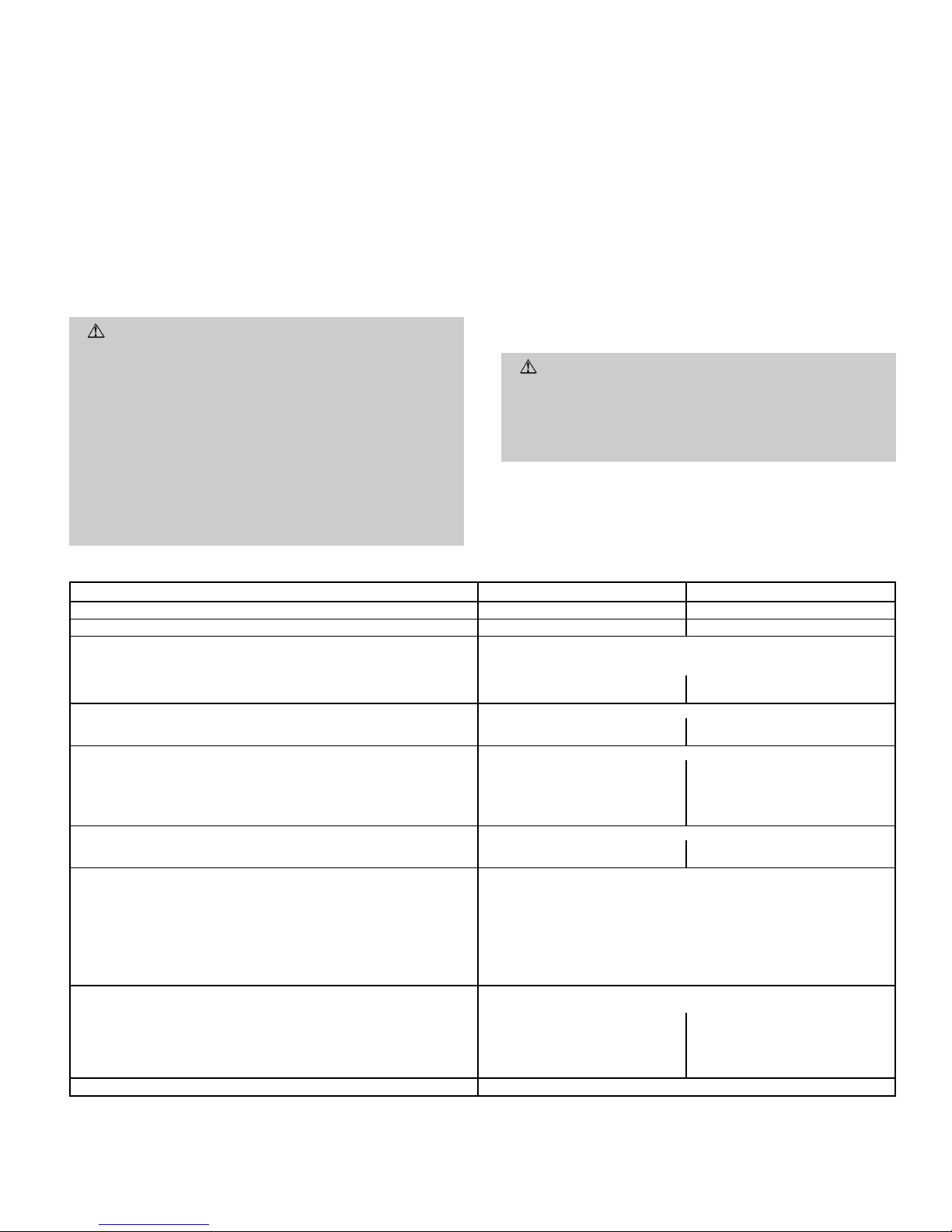
LEGEND
NEC — National Electrical Code
NOTE: Maximum system lift is 30 ft between lowest system compo-
nent and highest system component (see Fig. 7).
*See Connect Control Circuit Wiring section on page 9 for control
connection details.
Fig.6—Typical Piped System*
—6—
Page 7
IV. COMPLETE REFRIGERANT PIPING
NOTE: Complete all refrigerant tubing connections at the fan
coil units first. Then route the tubing sets back to the outdoor unit. Mark each tubing set carefully to identify its respective fan coil unit.
Outdoor units may be connected to indoor units using fieldsupplied tubing of refrigerant grade and condition. See
Table 1 for correct line sizes. Do not use less than 10 ft
of interconnecting tubing.
NOTE: It is not necessary to make any changes to line sizes
or any refrigerant system modifications when using recommended refrigerant line lengths.
When installing tubing, both the vapor return line and the
vapor supply (smaller) line must be insulated between outdoor unit and indoor unit to avoid condensation on the lines.
Use closed-cell foam insulation and tape all seams and joints.
CAUTION:
DO NOT BURY MORE THAN 36 IN. OF
REFRIGERANT TUBING IN THE GROUND. If any section of tubing is buried, there must be a 6-in. vertical
rise to the valve connections on the outdoor unit. If more
than the recommended length is buried, refrigerant may
migrate to cooler, buried section during extended periods of system shutdown. This causes refrigerant slugging and could possibly damage compressor at startup.
DO NOT USE MORE THAN 50 FT of EQUIVALENT
interconnecting tubing or more than 30 ft of VERTICAL lift (see Fig. 7) between the lowest system component and the highest system component.
If either refrigerant tubing or indoor coil is opened to atmospheric conditions for longer than 5 minutes, it must be evacuated to 1000 microns to eliminate contamination and moisture in the system.
Run refrigerant tubes as directly as possible, avoiding unnecessary turns and bends. Suspend refrigerant tubes so they
do not damage insulation on vapor return or supply tubes
and do not transmit vibration to structure. Also, when passing refrigerant tubes through wall, seal opening so that vibration is not transmitted to structure. Leave some slack in
refrigerant tubes between structure and outdoor unit to absorb vibration. See Fig. 5 for indoor to outdoor unit tubing
connections, and refer to separate indoor fan coil unit installation instructions for additional information.
NOTE: If only 2 fan coil units are used on 538S_048 sys-
tems, be sure that one is used with each compressor refrigerant circuit. If 2 or 3 fan coil units are used, cap any unused
refrigerant lines at the service valves.
WARNING:
DO NOT INSTALLAFIELD-SUPPLIED
FILTER DRIER in this system. Filter drier is factory
installed inside the outdoor unit. Installing a filter drier
in the liquid line between the indoor and outdoor units
will cause a high-pressure drop, and will result in abnormal system operation.
Table 1 — Specifications
UNIT 538S
_
024 048
NOMINAL CAPACITY (Tons) 24
OPERATING WEIGHT (lb) 159 292
REFRIGERANT TYPE R-22
Control (Cooling) TXV in Condensing Unit
Factory Charge (lb)*
Circuit A 5.0 5.5
Circuit B — 5.5
COMPRESSOR TYPE Copeland Scroll
Quantity...Model 1...ZR23K1 2...ZR49K3
Oil (Recharge) (oz) 25 53
OUTDOOR FAN Propeller, Direct Drive
Rpm 850 850
Diameter (in.)...No. of Blades 18...3 24...3
Pitch (Degrees) 27 24
Motor Hp
1
⁄
8
1
⁄
4
Nominal Air Cfm 1720 3900
OUTDOOR COIL Copper Tube, Aluminum Fin
Face Area (sq ft)...No. of Rows 6.1...2 12.3...2
Fins/in. 15 15
CONTROLS
High-Pressure (psig)
Cut-in 320±20
Cutout 426 ± 7
Low-Pressure (psig)
Cut-in 22 ± 5
Cutout 7± 3
Fusible Plug 210 F
Control Voltage 24
REFRIGERANT LINES
Connection Type Sweat
Vapor Supply Line Quantity...OD (in.) 2...
3
⁄
8
2†...3⁄
8
Vapor Return Line Quantity...OD (in.) 2...5⁄
8
2†...7⁄
8
Maximum Length (ft) 50 50
Maximum Lift (Fan Coil Above Outdoor) (ft) 30** 30**
Maximum Lift (Fan Coil Below Outdoor) (ft) 30** 30**
EXTERNAL FINISH Alpine Mist (Beige)
LEGEND
TXV — Thermostatic Expansion Valve
*Charge is based on 25 ft of interconnecting line.
†Per circuit.
**Maximum system lift is 30 ft between lowest system component and
highest system component.
—7—
Page 8
A. Make Piping Sweat Connections
Check tubing set identification against Multi-Split Installation Planning Worksheet on page CL-1 to ensure correct selection of service valve set on outdoor unit.
Remove plastic caps from vapor supply and vapor return service valves. Use refrigerant grade tubing. Service valves are
closed from the factory and are ready for brazing. Passnitrogen or other inert gas through piping while brazing to prevent formation of copper oxide.
After wrapping the service valve with a wetcloth, the tubing
set can be brazed to the service valve using either silver bearing or non-silver bearing brazing material. Consult local code
requirements. Refrigerant tubing and indoor coil are now ready
for leak testing.
NOTE: Unit is shipped from the factory with a full system
charge of R-22 (exact amount is indicated on unit nameplate).
CAUTION:
To avoid damage while brazing, service
valves should be wrapped with a heat-sinking material
such as a wet cloth.
CAUTION:
When brazing tubing sets to the service
valves, a brazing shield MUST be used to prevent damage to the painted unit surface.
B. Provide Safety Relief
A fusible plug is located in unit vapor return line; do not cap
this plug. If local code requires additional safety devices, install as directed.
C. Leak Test, Evacuate, and Dehydrate System
Refer to Leak Test and Evacuate and Dehydrate sections on
page 13 for details.
V. MAKE ELECTRICAL CONNECTIONS
WARNING:
Unit cabinet must have anuninterrupted,
unbroken electrical ground to minimize the possibility
of personal injury if an electrical fault should occur.This
ground may consist of electrical wire connected to unit
ground lug in control compartment, or conduit approved for electrical ground when installed in accordance with NEC, ANSI/NFPA 70, and local electrical
codes. Failure to follow this warning could result in the
installer being liable for personal injury of others.
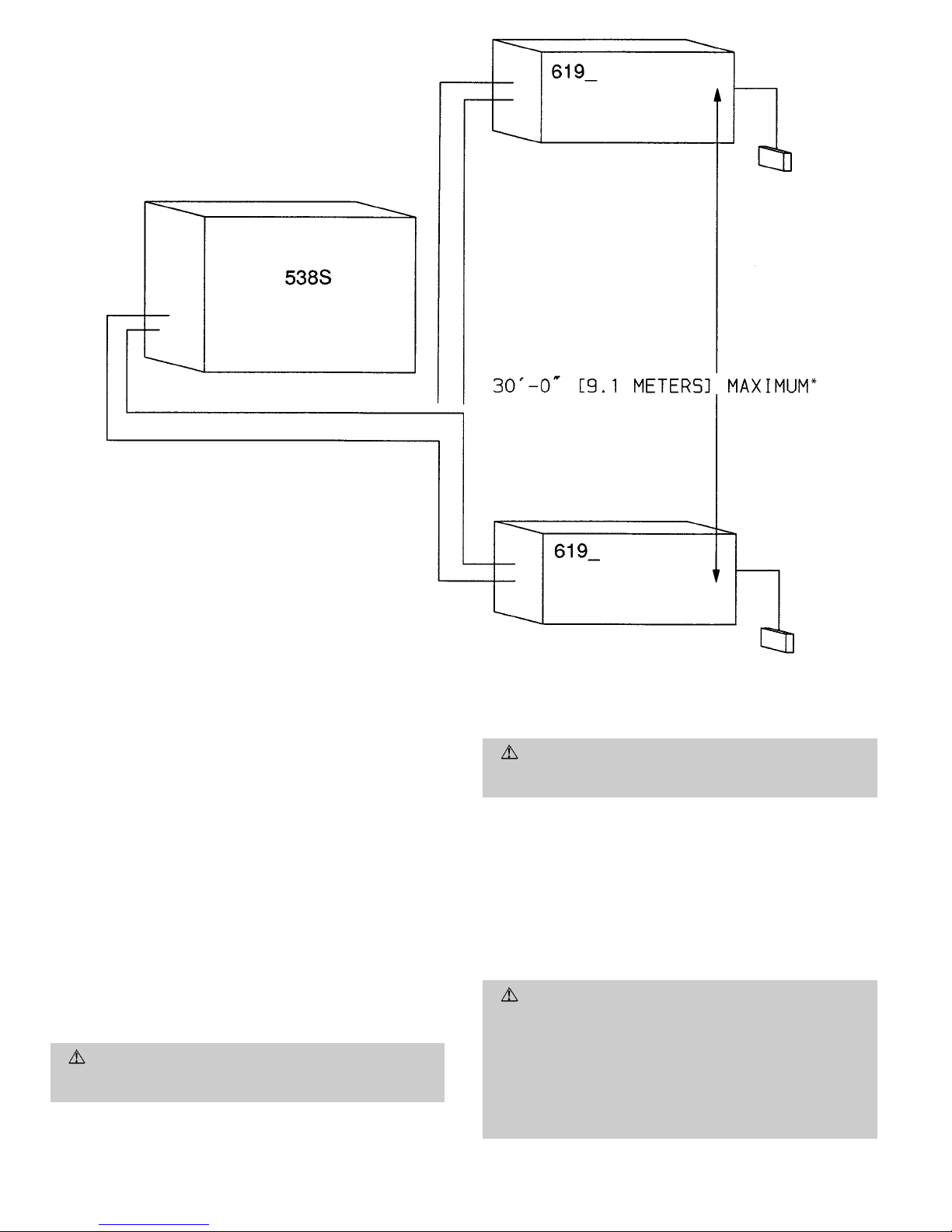
*The maximum system elevation is 30 ft from lowest point in the
system to highest point in the system.
Fig. 7 — Maximum Elevation Differential
—8—
Page 9
CAUTION: Unit failure as a result of operation on
improper line voltage or excessive phase imbalance constitutes abuse and may cause damage to electrical components. Do not install units in system where voltage
may fluctuate above or below permissible limits. Such
operation would invalidate any applicable warranty.
A. Outdoor Condensing Unit
Be sure field wiring complies with local and national fire, safety,
and electrical codes, and that voltage to the system is within
limits shown in Table 2. Contact local power company for correction of improper line voltage.
See Table 2 for recommended fuse sizes. When making electrical connections, provide clearance at unit for refrigerant
piping connections.
B. Install Branch Circuit Disconnect Per NEC
Install a disconnect of adequate size to handle unit starting
current. Locate disconnect within sight from and readily accessible from unit per Section 440-14 of NEC.
C. Route Line Power Leads
Extend leads from disconnect through power wiring hole provided and into unit splice area. Remove outdoor unit control
box cover to gain access to unit wiring.
NOTE: Power leads from disconnect into outdoor unit must
be COPPER WIRE ONLY.
D. Connect Ground Lead and Power Wiring
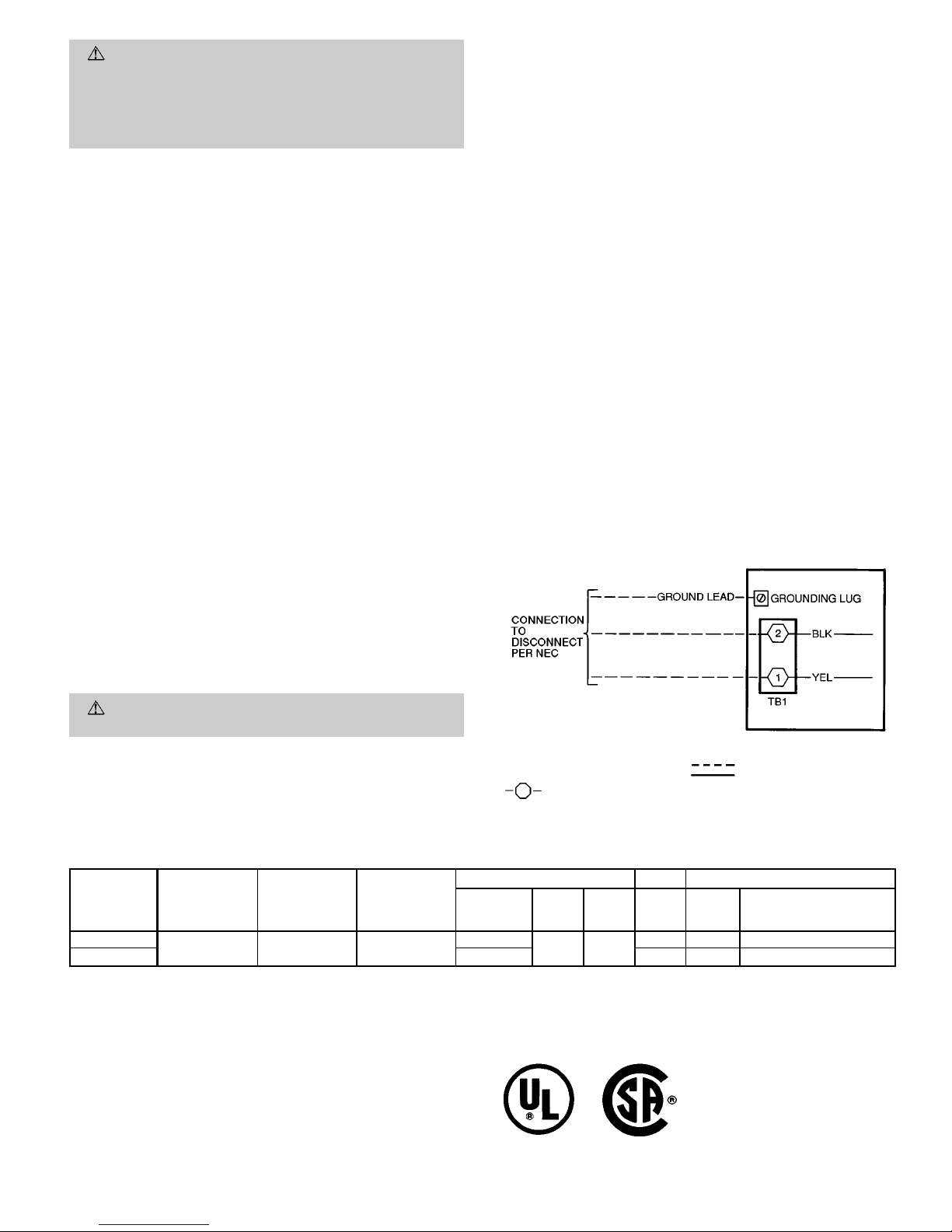
Connect ground lead to equipment ground connection in outdoor unit control box. Then connect power wiring to TB1
(terminal block no. 1). See Fig. 8. Splice the line power leads
to yellow and black leads provided.
E. Indoor Unit
Refer to installation instructions included with the fan coil
units for fan coil unit installation and power supply details.
F. Connect Control Circuit Wiring
WARNING:
To avoid personal injury, be sure system
main power switch is turned off before proceeding.
1. Refer to Multi-Split Installation Planning Worksheetcompleted prior to the start of this installation and verify
the markings on each set of control wiring cable sets.
2. Route 24-v control wiring through wiring hole on the outdoor unit. See Fig. 9 for typical connections for each type
of fan coil. See. Fig. 10 and 11 for 538S component arrangement and unit wiring details. See Fig. 12 for 538S
to fan coil unit control wiring connection details.
3. Connect wiring to screw connections labeled FC1, FC2,
FC3, and FC4 on terminal board for each corresponding
fan coil unit. See Fig. 9-12.
4. Route the other end of the control wiring back to the
fan coil unit and connect to the fan coil terminal board
according to the wiring schematic for the fan coil unit.
See fan coil unit installation instructions for wiring
schematic.
G. Connect Thermistor Wiring
1. Refer to fan coil unit installation instructions for location of thermistor harness assemblies (not used on 619F
units). The installation instructions are shipped with each
fan coil unit. Connect the outdoor unit thermistor harness plugs at the matching fan coil unit terminal blocks.
2. Label each thermistor harness per the previously completed Multi-Split Installation Planning Worksheet.
3. Route the thermistor harness assemblies from the outdoor unit to the indoor fan coil units.
IMPORTANT: DO NOT RUN THE THERMISTOR
CABLES IN THE SAME CONDUIT AS THE CONTROL CIRCUIT OR POWER WIRING.
4. Route harnesses into 538S unit junction box.
5. Connect each thermistor plug to its matching plug in
the outdoor condensing unit.
Table 2 — Electrical Data
UNIT SIZE
538S
_
V-PH-Hz
OPERATING
VOLTAGE
MINIMUM*
OPERATING
VOLTAGE
MAXIMUM*
COMPRESSOR FAN POWER SUPPLY
Quantity
RLA
(Ea)
LRA
(Ea)
FLA MCA
Max Fuse
or HACR-Type
Circuit Breaker Amps
024
208/230-1-60 187 254
1
12.9 62.5
0.70 16.8 25
048 2 1.45 30.5 40
LEGEND
FLA — Full Load Amps
HACR — Heating, Air Conditioning, Refrigeration
LRA — Locked Rotor Amps
MCA — Minimum CircuitAmps
NEC — National Electrical Code
RLA — Rated Load Amps (Compressor)
*Permissible limits of the voltage range at which unit will operate
satisfactorily.
NOTES:
1. The 538S units contain a 24-v transformer; additional transformers
are not required.
2. All motors and compressors contain internal overload protection.
3. In compliance with NEC requirements for multimotor and combination load equipment (refer to NEC Articles 430 and 440), the overcurrent protective device for the unit shall be fuse or HACR breaker.
4. Motor RLAvalues are established in accordance with UL (Underwriters’ Laboratories) Standard 1995.
LEGEND
NEC — National Electrical Code
Field Wiring
TB — Terminal Board
Factory Wiring
TB Connections
Fig. 8 — Line Power Connections
—9—
Page 10
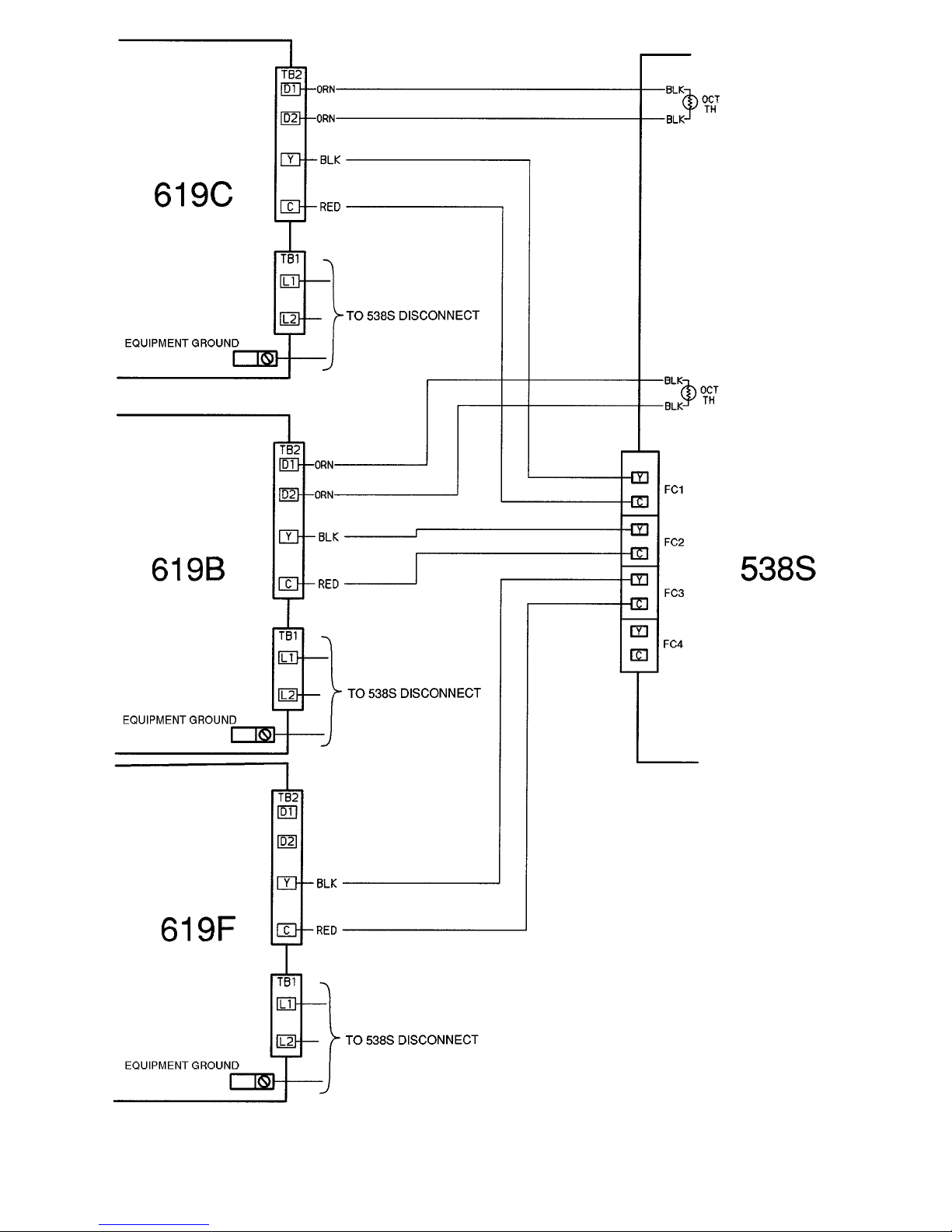
LEGEND
FC — Fan Coil Unit
OCT TH — Outdoor Coil Temperature Thermistor
TB — Terminal Block
Fig. 9 — Control Line Connections (Typical Connections for Each Type of Fan Coil Illustrated)
—10—
Page 11
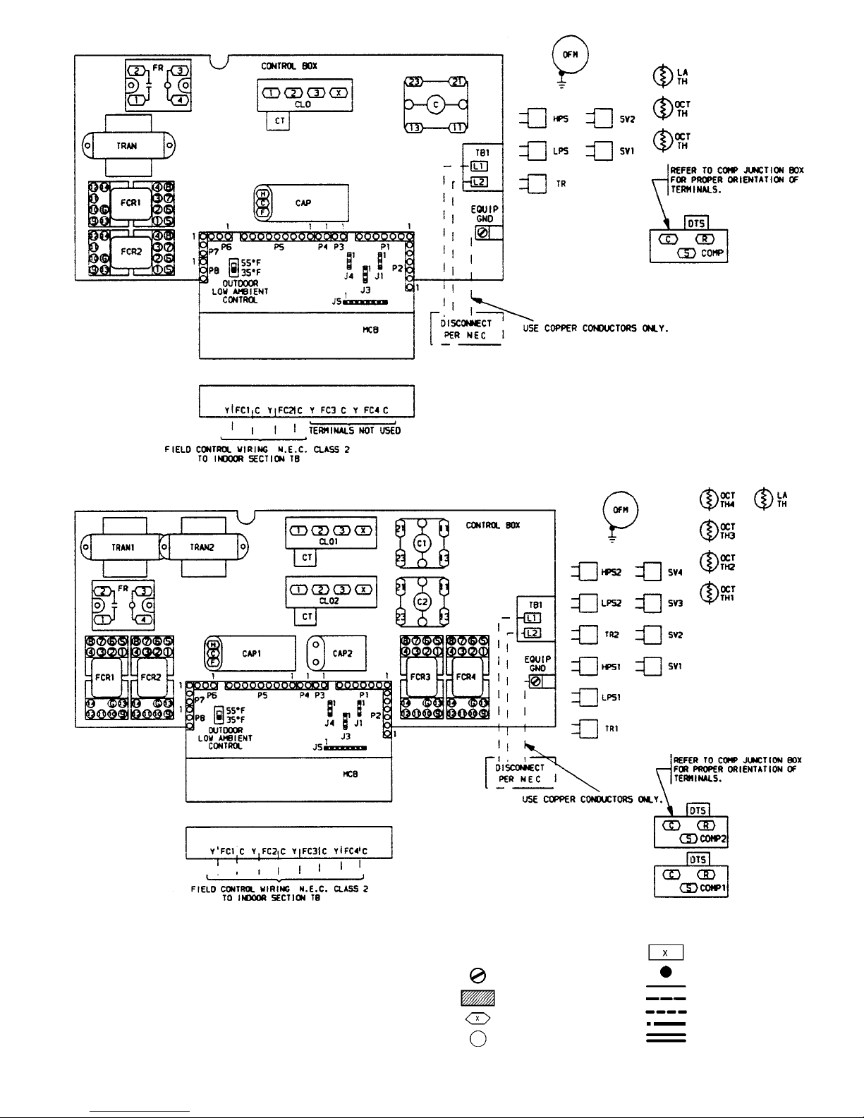
Fig. 10 — Component Arrangement, 538S_024
Fig. 11 — Component Arrangement, 538S_048
LEGEND FOR FIG. 10 AND 11
C—Contactor, Compressor
CAP — Capacitor
CLO — Compressor Lock Out
COMP — Compressor Motor
CT — Current Transformer
DTS — Discharge Temperature
Switch
EQUIP — Equipment
FC — Fan Coil Unit
FCR — Fan Coil Relay
FR — Fan Relay
GND — Ground
HPS — High-Pressure Switch
J—Connector
LPS — Low-Pressure Switch
LA — Low Ambient
MCB — Multi-Split Control Board
NEC — National Electrical Code
OCT — Outdoor Coil Temperature
OFM — Outdoor-Fan Motor
P—Connector
SV — Solenoid Valve
TB — Terminal Block
TH — Themistor
TR — Transducer
TRAN — Transformer
Terminal (PCB, Field)
Terminal (PCB, Factory)
Terminal (Marked)
Terminal (Unmarked)
Terminal Block
Splice
Factory Wiring
Field Control Wiring
Field Power Wiring
Option or Accessory Wire
PCB Run
—11—
Page 12
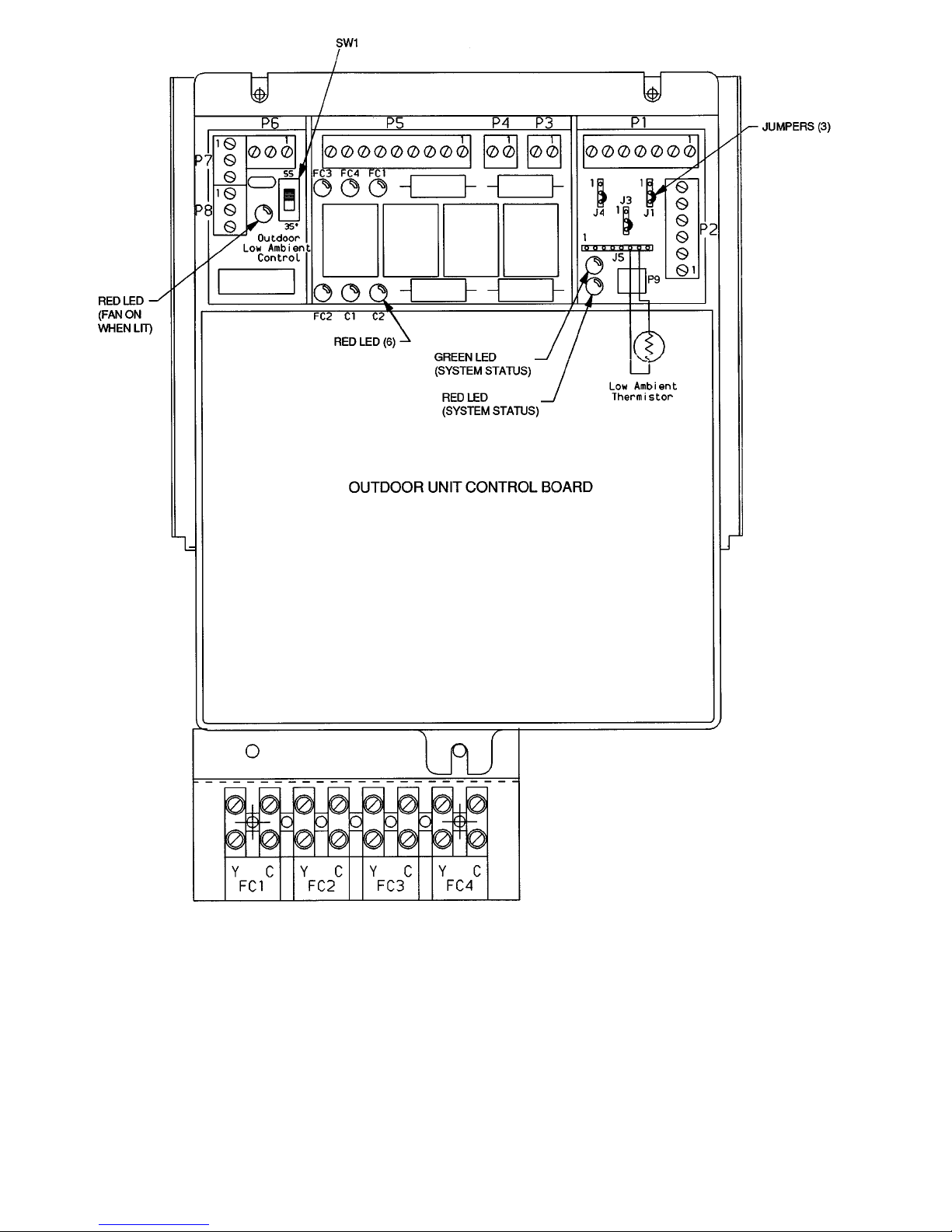
LEGEND
C—Compressor
FC — Fan Coil
J, P — Connectors
LED — Light-Emitting Diode
SW — Switch
Fig. 12 — Outdoor Unit Microprocessor Control Board
—12—
Page 13
H. Reconfigure for One Fan Coil Unit per Compressor
Circuit if Necessary
The control also provides the option of using either 1 or 2fan
coil units per compressor (depending on the position of the
jumpers on J3 and J4 on the control board). See Fig. 12. The
control is preset to 2 fan coil units per compressor at the factory. If only one fan coil per compressor is to be used, position
a jumper between pins 1 and 2 on J3 and J4 (one jumper for
each set of pins). Jumper J3 is associated with the compressor on the 538S_024 units and compressor number 1 on
538S_048 units (bottom compressor). Jumper J4 is associated with compressor number 2 on the 538S_048 units.
START-UP
I. LEAK TEST
Field piping and all tubing connections must be leak tested
by the pressure method. Use R-22 at approximately 25 psig
backed up with an inert gas to reach a total system pressure
not to exceed 245 psig.
II. EVACUATE AND DEHYDRATE
Field piping and fan coil must be evacuated and dehydrated
to 1,000 microns using accepted practices.
WARNING:
Service valves must be fully backseated
to close service port. There is no Schrader valve at the
service port, and failure to backseat the valve could result in loss of system charge or personal injury.
III. CHARGE SYSTEM
Release charge into system by opening (backseating) vapor
supply and vapor return line service valves. Open ONL Ythose
service valve sets which have fan coil unit sections connected
to them. DO NOT open valves where no field tubing has been
connected.
IV. PRELIMINARY CHECKS
Complete Start-Up Checklist on page CL-1 and the following
checks prior to starting up unit.
1. Check condensate drainage system. T odo this, add a small
amount of water into each fan coil unit condensate pan,
and ensure that each pan drains freely. Inspect drain
pans and lines, and clean as required.
2. Make sure that all wiring connections are correct and
tight.
3. Check all barriers, covers, and panels to ensure they are
in place.
4. Identify which fan coil unit valve sets have been
connected.
IMPORTANT: DO NOT open valves which do not have
fan coil units connected to them.
5. Unit is shipped with the valve stems frontseated and
caps factory installed. Remove caps from all valves to
which fan coil units have been connected. Replace caps
and tighten until finger tight.
6. Fully backseat (open) the vapor supply and vapor return tube service valves.
7. Turnon main disconnect switch(es) to indoor fan coil units
and outdoor condensing unit.
8. Using the remote controller for each indoor fan coil unit,
turn on each fan coil unit and operateeach unit in each
mode (i.e., electric heat [if provided], and fan cooling)
for 15 minutes to test for proper operation.
9. Test for proper refrigerant charge in each circuit using
the subcooling method.
V. OPERATING SEQUENCE
NOTE: AUTO. fan mode is used as the unit operation ex-
ample for ALL fan coil units in this section. Contact your local Carrier dealer for operationinformation in other fan modes.
A. Fan Coil Units
Each fan coil unit has a self-contained control system that
determines the set point for fan coil operation, fan mode operation, and heating mode operation (if provided). The 619B
and 619C fan coil units are equipped with either a wired or
wireless remote controller set (remote controller is not available for 619F fan coil units). Set points and fan modes may
be determined separately for each fan coil unit.
Each fan coil unit may call for cooling operation independently. On a call for cooling operation by a single fan coil unit,
a 24-v signal is sent to the 538S outdoor unit and energizes a
control relay. The indoor blower starts according to the normal fan coil unit sequence of operation. The control relay (in
the outdoor unit) initiates operation of a cooling cycle for the
respective indoor unit refrigerant circuit; including opening
a liquid line solenoid valve in the outdoor unit.
As the set point at each fan coil is satisfied, its individual
24-v signal to the 538S unit stops, and the respective solenoid valve for each fan coil unit closes. The indoor fan cycles
off. The 619B and 619C fan coil units then begin room sampling operation after a 3-minute off period (during sampling,
the fan motor runs at low speed for 1 minute to sample the
demand in the space; then cycles off until the next sampling
period if no demand is found).
B. 538S Outdoor Condensing Unit
The outdoor unit is equipped with a control that will monitor
the indoor fan coil unit cooling request. The control will turn
on solenoid valves for the appropriate indoor fan coil unit system. The control will also combine the cooling requests to control up to 2 compressors.
The control provides a 2-minute compressor time-delay device which disables the compressor for 2 minutes. The time
delay device timers will be initialized when the unit is powered up (for the first 2 minutes).
The 538S unit control includes an integral head pressure control function. This function will maintain a minimum head
pressure by cycling the outdoor fan motor in response to inputs from the thermistor (for outdoor ambient temperature)
and the transducers (for system discharge pressures in each
compressor circuit).
The head pressure for the compressor(s)will be monitored to
control the outdoor fan output. The control reads an outdoor
temperature thermistor to determine if thehead pressure should
be used to control the outdoor fan output.
Operation
The 538S unit receives a 24-v control signal from each fan
coil unit as each fan coil unit initiates a demand for cooling.
The 24-v signal energizes a control relay in the 538S unit (one
relay per fan coil unit). The refrigerant flow to each fan coil
unit is controlled through a solenoid valve (one valve per fan
coil unit). The solenoid valve(s) will not open until compressor operation is initiated by the controller.
The microprocessor control inthe 538S unit includes a 2-minute,
anti-short cycle, time-delay function. This function provides
a minimum time-off delay between compressor run stages
(2 minutes each from the end of the last on period to the beginning of the next on period). If more than 2 minutes have
passed since the end of the last on period, the compressor
will be ready to restart with initiation of demand from any
fan coil unit on its circuit.
—13—
Page 14
Increased Demand for Cooling
NOTE: There are 2 separate compressor circuits in the
538S_048 units (circuit A and circuit B). Each circuit operates independently, and will operate as follows (as will the
single-circuit 024 units) upon receiving the first 24-v cooling
demand signal from a fan coil unit:
1. After the 2-minute time-delay function is satisfied, the
appropriate compressor starts.
2. The solenoid valve connected to the fan coil sending the
demand signal is energized (at the 538S units).
3. The outdoor fan starts, and its operation is controlled
by the microprocessor as described in 538S Microprocessor Control of Outdoor Fan section below.
When a second fan coil unit signals a demand for cooling, its
associated solenoid valve is energized immediately, allowing
refrigerant to flow to both fan coil units simultaneously.
Decreased Demand for Cooling
When a fan coil unit’s demand for cooling ends, the 24-v sig-
nal to the 538S unit stops, and the appropriate solenoid valve
closes. If the other fan coil unit on this circuit still has a demand, the appropriate compressor will continue to run as long
as necessary for the second fan coil unit.
When the second fan coil unit’s demand for cooling ends, its
solenoid valve closes, and the appropriate compressor stops.
The compressor will not start for at least 2 minutes after the
end of this cycle due to the time-delay function.
On size 024 units, when the compressor stops, the outdoor
fan also stops. On size 048 units, outdoor fan operation may
continue under control of the 538S microprocessor if the other
refrigerant circuit is still operating. The outdoor fan will only
stop when both compressors are off. Refer to 538S Microprocessor Control of Outdoor Fan section below for more
details.
C. 538S Microprocessor Control of Outdoor Fan
The microprocessor control has a built-in head pressure control system that will cycle the outdoor-fan motor to maintain
a selected discharge pressure. The microprocessor senses outdoor ambient temperature using a thermistor and refrigerant pressure using a pressure transducer mounted on the
compressor circuit discharge line. The 538S_024 units have
one transducer, and the 048 units have two.
The factory set points for the head pressure control operation are 55 F for outdoor ambient temperature and 250 psig
for discharge pressure.
When the outdoor ambient temperature is above theoutdoor
ambient set point and both fan coils on a compressor circuit
are calling for cooling operation, the outdoor fan will run at
full speed whenever compressor operation is permitted. When
only one fan coil on a circuit is calling for cooling, fan cycling
is permitted at all ambients. Fan motor will becycled on and
off to maintain set point discharge pressure.
When the outdoor ambient temperature is below the specified set point, the fan motor will be cycled on and off to maintain a compressor discharge pressure at the specified pressure set point. On 538S_048 units with 2 compressors running,
the compressor with the lower head pressure will control the
fan operation. If only one compressor is running, that compressor will control the fan operation.
If the discharge pressure on either circuit exceeds 370 psig,
the outdoor-fan motor will run continuously, and the fan cycling function will be bypassed until the discharge pressure
decreases to 365 psig.
Units can be field configured to select head pressure control
at 35 F outdoor ambient and/or 200 psig discharge pressure.
D. Status Indicator Lights
The 538S control board is equipped with LED indicators to
aid in evaluating the status of the control system, including
(see Table 3):
• time delay function status
• fan coil unit demand status
• head pressure control status
• current unit malfunctions
E. Unit Malfunction
Each compressor circuit isequipped with a high-pressure switch
(HPS), a loss-of-pressure switch (LPS), and a discharge temperature switch (DTS). These safety devices are located in a
Cycle-LOC™ device circuit that prevents compressor operation if any of these safety devices is activated. The lockout
can be reset by turning the main power to the 538S unit off,
then on again.
Compressor overcurrent protection is achieved by an internal linebreak overload, which will automatically reset when
the motor temperature cools to a satisfactory level. Manual
reset of Cycle-LOC circuit may also be required (turn main
unit disconnect to OFF, then to ON position).
Pressure transducers and the outdoor ambient thermistor are
monitored by the 538S controller. If a pressure transducer is
found to be out of range, the LEDs will flash a code for this
fault, but the control will continue to cycle the outdoor fan
according to input from the other transducer.If only one transducer is active and is determined to be out of range, the head
pressure control will be bypassed and the fan will run continuously. If the thermistor is found to be out of range, the
control will allow fan cycling per transducer input, and the
LEDs will flash a code for this failure. See Table 3.
Table 3 — System Status Red and Green LEDs and Fault Codes
GREEN LED RED LED
UNIT STATUS
Number of
Flashes On
Number of
Flashes Off
Number of
Flashes On
Number of
Flashes Off
1 1 — Always Off System Ready
1111 LowHead Pressure, Circuit 1
1122 High Head Pressure, Circuit 1
1133 LowHead Pressure, Circuit 2
2211 High Head Pressure, Circuit 2
2222LowOutdoor Ambient Temperature, Outdoor Thermistor
2233High Outdoor Ambient Temperature, Outdoor Thermistor
3311 Hardware Error
3322 TimeGuardT Device Active, Circuit 1
3333 TimeGuard Device Active, Circuit 2
LED — Light-Emitting Diode
—14—
Page 15
SERVICE
WARNING:
Before performing recommended maintenance, be sure unit main power switch is turned off,
and be sure all disconnects for indoor fan coil units are
open. These systems typically have one disconnect per
fan coil unit. Failure to turn off unit main power and
open all disconnects may result in electrical shock or
injury from rotating fan blade.
I. OUTDOOR FAN
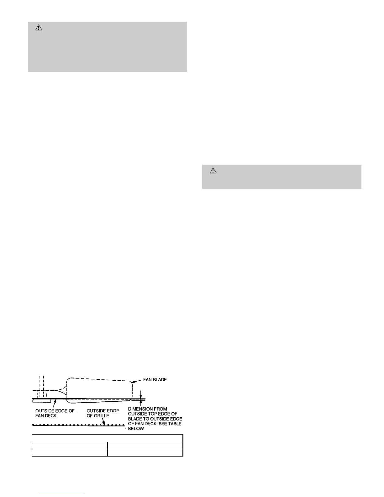
A reinforced wire mount holds the outdoor fan assembly in
position. See Fig. 13 for proper mounting positions.
II. SCROLL COMPRESSORS
The 538S condensing units use scroll compressors. The
538S_024 unit has one compressor, and the 538S_048 unit
has 2 compressors which are stacked vertically (using a sheet
metal stand to support the top compressor). In the event of a
compressor failure, remove and replace the compressor(s) as
follows:
1. Attach refrigerant hose to vapor return line service valve
of the circuit related to the defective compressor.
2. Recover refrigerant using accepted techniques.
3. Remove discharge and suction piping from compressor
by unsweating. Pass either nitrogen or another inert gas
through the compressor.
4. Remove compressor mounting bolts. Use a swivel socket
to remove the bolt in the rear.
5. Carefully pull compressor stand and piping away from
the compressor to remove the compressor.
6. Reverse Steps 1-5 to install the new compressor.
A. Time-Delay Device Override
The time delay device can be overridden for easier unit servicing by temporarily shorting the time delay device override
connector (P9) located in the control box. See Fig. 12. The
short MUST be removed before the time delay device timer
can be cleared.
B. System Status LEDs and Fault Codes
In normal operating mode, the green LED located on the outdoor unit microprocessor board will flash on and off at a rate
of once per second. Whenever a fan coil unit, compressor, or
outdoor fan is energized, a red LED designated for each fan
coil unit will be illuminated. If there is an error condition, a
code will be displayed using the green and red system status
LEDs. The green LED will blink its code first, followed by
the red LED. The LEDs will flash at a rate of once every
2 seconds, with a 2-second pause between the last red LED
flash and the first green LED flash of the next code. See
Table 3.
III. HIGH-PRESSURE RELIEF VALVE
Valve is located in compressor. Relief valve opens at a pressure differentialof approximately 4506 50 psig between suction (low side) and discharge (high side) to allow pressure
equalization.
IV. INTERNAL CURRENT AND TEMPERATURE SENSITIVE
OVERLOAD
Control resets automatically when internal compressor motor temperature drops to a safe level (overloads may require
up to 45 minutes to reset). When aninternal overload is suspected of being open, check by using an ohmmeter or continuity tester.
V. HIGH-PRESSURE SWITCH
This switch, located on discharge line, protects against high
discharge pressures caused by such events as overcharge,
condenser-fan motor failure, system restriction, etc. It opens
on pressure rise at about 426 psig. If system pressures go
above this setting duringabnormal conditions, the switch opens.
WARNING:
DO NOT attempt to simulate these system abnormalities — high pressures pose a serious safety
hazard.
High-pressure switch is checked with an ohmmeter. If system pressure is below approximately 320 psig, switch shows
continuity. The high-pressure switch will reset automatically
after CLO (compressor lockout switch) has been reset and timedelay device has completed its timing cycle.
NOTE: If pressure switch needs to be replaced, there is a
Schrader valve located under the switch so that system will
not need to be evacuated.
VI. LOW-PRESSURE SWITCH
This switch, mounted on the vapor return line, has fixed, nonadjustable settings. To check pressure switch, attach pressure gage to vapor return line service valve gage port. Slowly
close liquid shutoff valve and allow compressor to pump down.
Do not allow compressor to pump down below 2 psig. Compressor should shut down when suction pressure drops to about
7 psig, and should restart when pressure builds up to about
22 psig after CLO has been reset and time-delay device has
completed its timing cycle.
NOTE: If pressure switch needs to be replaced, there is a
Schrader valve located under the switch so that system will
not need to be evacuated.
VII. SERVICE VALVES
The service valves in the outdoor unit are frontseated at the
factory. This means the refrigerant charge is isolated from
the line-set connection ports. Toprevent damage to the valve,
use a wet cloth or other accepted heat sink material on the
valve before brazing.
The service valves must be backseated (turned counterclockwise until seated) before the service port caps are removed and the hoses of gage manifold connected. In this position, refrigerant has access from and through outdoor and
indoor unit. The service valve cannot be field repaired; only a
complete valve or valve stem seal and service port caps are
available for replacement.
NOTE: Do not open service valves which are not connected
to a tubing set. Be sure any inactive circuits are capped off.
UNIT SIZE — in. (mm)
538S_024 538S_048
.709 (18) .16 (4)
Fig. 13 — Condenser-Fan Mounting Positions
—15—
Page 16
VIII. REFRIGERANT CHARGING
WARNING:
To prevent personal injury, wear safety
glasses and gloves when handling refrigerant. Do
not overcharge system — this can cause compressor
flooding.
WARNING:
Service valves must be fully backseated
to close service port. There is no Schrader valve at the
service port, and failure to backseat the valve could result in loss of system charge or personal injury.
NOTE: Do not vent or depressurize unit refrigerant to atmosphere. Remove and recover refrigerant following accepted
practices.
The 538S units are factory charged with a full operatingcharge.
Check the system for proper charge level using the subcooling method.
If a refrigerant system must be opened for major service work,
first recover refrigerant in system using accepted practices.
Evacuate and dehydrate the system whenready to recharge;
then weigh in the proper refrigerant quantity (as marked on
the unit data plate for each circuit.)
A. Subcooling Charging Method
1. Operate the unit a minimum of 15 minutes before checking the charge.
2. Measure discharge pressure by attaching an accurate
gage to the discharge service port. DO NOT use the external service valves for this pressure reading.
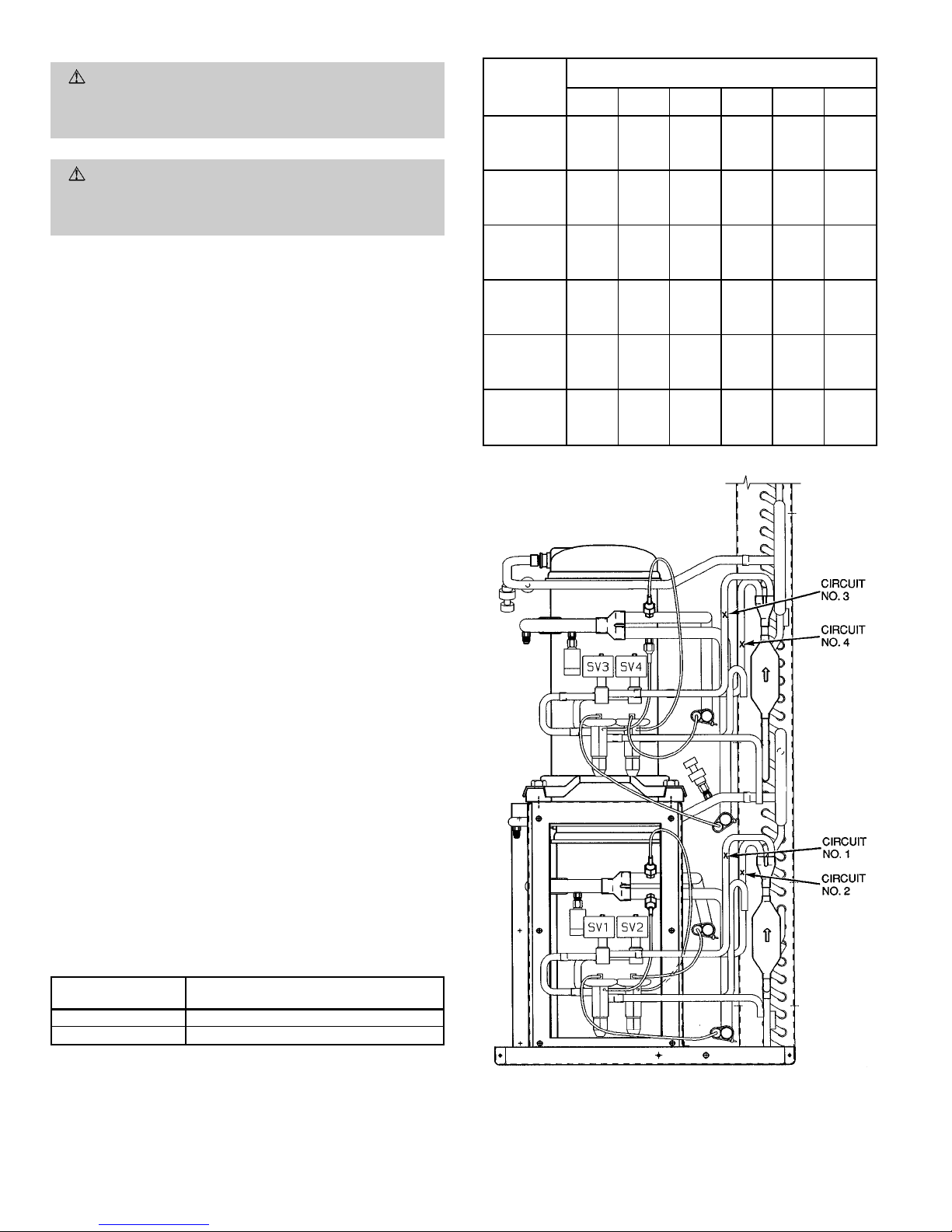
3. Measure the vapor supply line temperature by attaching an accurate thermistor-type or electronic thermometer to the vapor supply line near the outdoor coil. See
Fig. 14.
4. Refer to Table 4 to find the required subcooling temperature for the unit. Find the point at which the required
subcooling temperature intersects the measured internal discharge service port pressure in Table 5.
5. To obtain the requiredsubcooling temperature at a specific discharge pressure, add refrigerant if vapor supply
line temperature is higher than indicated, or remove refrigerant if temperature is lower than indicated. Allow
a tolerance of ± 3%.
IX. COMPRESSOR LOCKOUT SWITCH (CLO)
Units are provided with compressor lockout protective device. If the compressor shuts down due to any safety device,
a current loop monitoring the compressor current senses no
current flow. The unit will lock out until the control power is
interrupted to reset the lockout. Determine reason for safety
trip. To restart, turn the 538S main disconnect to OFF, then
to ON position.
Table 4 — Required Unit Subcooling
UNIT 538S
_
SUBCOOLING AT TXV INLET (F)
WITH ALL FANS OPERATING
024 19
048 16
TXV — Thermostatic Expansion Valve
Table 5 — Required Liquid Line Temperatures
PRESSURE
(Psig) AT
SERVICE
FITTING
REQUIRED SUBCOOLING TEMPERATURE (F)
0 5 10 15 20 25
134 76 71 66 61 56 51
141 79 74 69 64 59 54
148 82 77 72 67 62 57
156 85 80 75 70 65 60
163 88 83 78 73 68 63
171 91 86 81 76 71 66
179 94 89 84 79 74 69
187 97 92 87 82 77 72
196 100 95 90 85 80 75
205 103 98 93 88 83 78
214 106 101 96 91 86 81
223 109 104 99 94 89 84
233 112 107 102 97 92 87
243 115 110 105 100 95 90
253 118 113 108 103 98 93
264 121 116 111 106 101 96
274 124 119 114 109 104 99
285 127 122 117 112 107 102
297 130 125 120 115 110 105
309 133 128 123 118 113 108
321 136 131 126 121 116 111
331 139 134 129 124 119 114
346 142 137 132 127 122 117
359 145 140 135 130 125 120
LEGEND
SV — Service Valve
X—Measurement Location
Fig. 14 — Vapor Supplly Line Measurement
Locations (538S_048 Unit Shown)
—16—
Page 17
X. OUTDOOR-COIL TEMPERATURETHERMISTOR (OCT TH)
Thermistor is for use only with duct-free split systems employing a microprocessor control (619B and 619C fan coil units
only) as part of the system diagnostics. Refer to separate installation instructions for the 619B and 619C indoor units.
The thermistor is mounted in a well attached to the condenser coil. See Table 6 for thermistor characteristics.
NOTE: The 619F in-ceiling fan coil units use 24-v electromechanical controls for system diagnostics. Refer to 619F installation instructions for more details.
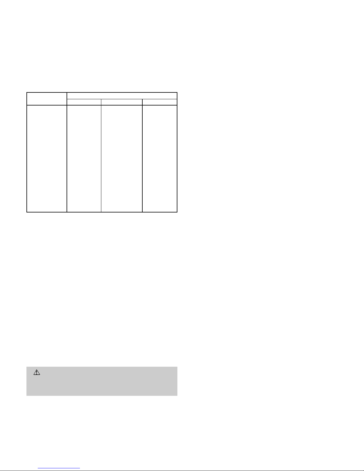
Table 6 — Thermistor Characteristics
TEMP (F)
RESISTANCE (OHM)
MIN NOMINAL MAX
20 36,230 37,100 37,980
30 28,330 28,930 29,540
32 26,870 27,430 27,990
40 22,320 22,740 23,160
50 17,710 17,990 18,280
60 14,230 14,420 14,620
70 11,490 11,630 11,760
77 9,900 10,000 10,100
80 9,340 9,440 9,540
90 7,610 7,700 7,800
100 6,230 6,320 6,410
110 5,130 5,220 5,310
120 4,250 4,340 4,420
130 3,550 3,620 3,690
140 2,960 3,030 3,100
150 2,500 2,560 2,620
160 2,120 2,170 2,230
170 1,810 1,850 1,900
180 1,540 1,580 1,630
190 1,320 1,360 1,400
200 1,140 1,170 1,210
210 980 1,020 1,050
212 954 986 1,019
220 853 882 912
230 742 769 796
NOTES:
1. A high quality digital volt-ohmmeter is required to check thermistor resistance.
2. Measure temperature at thermistor location with an accurate thermocoupletype temperature measuring instrument.
3. If a more accurate check is required, thermistor must be removed and checked
at a known temperature (freezing point or boiling point of water).
XI. LOW-AMBIENT CONTROL THERMISTOR (LAT)
The low-ambient control thermistor is located on the outdoor
fan support bracket. See Operating Sequence section on
page 13 and Fig. 12 for more information about the controls.
XII. PRESSURE TRANSDUCER
The pressure transducer activatesthe low-ambient control when
discharge pressure drops to either 250 psig or 200 psig based
on the setting of control jumper J1. See Operating Sequence
section on page 13 for more information about the controls.
If transducer has to be removed for any reason, first disconnect the snap lock plug. The transducer can now be unscrewed and removed without loss of refrigerant since there
is a Schrader-type core valve in the transducer port. When
reinserting the transducer, reverse this procedure. Be careful not to overtighten the transducer.
MAINTENANCE
WARNING:
Before performing recommended maintenance, be sure unit main power switch is turned off.
Failure to do so may result in electric shock or injury
from rotating fan blade.
I. LUBRICATION
A. Fan-Motor Bearings
Oiling holes are provided at each end of condenser-fan motor.
Remove fan motor and lubricate motor with 32 drops (16 drops
per hole) of SAE-10 (Society of Automotive Engineers) nondetergent oil at the following intervals:
• Annually when environment is very dirty, ambient temperature is higher than 105 F, and average unit operating
time exceeds 15 hours a day, or
• Every 3 years when environment is reasonably clean, ambient temperature is less than 105 F, and unit operating
time averages 8 to 15 hours a day, or
• Every 5 years when environment is clean, ambient temperature is less than 105 F, and unit operating time averages less than 8 hours a day.
B. Compressor
Compressor contains factory oil charge; replace oil when lost.
See Table 1 for oil recharge.
NOTE: Use only Cryol 150A oil in these units.
II. CLEANING COILS
Coil should be washed out with water or blown out with compressed air. Note that the blow-thru design causes dirt and
debris to build up on the inside of the coils.
Clean coil annually or as required by location and outdoor
air conditions. Inspect coil monthly and clean as required. Fins
are not continuous through coil sections. Dirt and
debris may pass through first section, become trapped between the rows of fins, and restrict condenser airflow. Use a
flashlight to determine if dirt or debris has collected between
coil sections. Clean coil as follows:
1. Turn off unit power.
2. Using a garden hose or other suitable equipment, flush
coil from the outside to remove dirt. Be sure to flush all
dirt and debris from drain holes in base of unit. Fan motors are waterproof.
TROUBLESHOOTING
I. CHECKING COOLING CONTROL OPERATION
Check the system for proper control operation as follows (refer to Troubleshooting Chart on page 18 for more details):
1. Check status LED at the 538S control board. A green
LED will flash on and off at one-second intervals when
the unit is ready to run. If a time delay function is active (3 green LED flashes followed by 2 or 3 red LED
flashes), wait 2 minutes for time delay to clear.
2. At a fan coil unit remote controller, (619B or 619C units)
select AUTO fan mode, COOL system mode, and adjust
set point down until thermometer segment is fully displayed. Notice the snowflake display on the handset (system mode is COOL) and the compressor run display
(demand signal is being sent to the outdoor unit). Note
that the indoor fan starts at low speed.
For 619F units, position selector switch at subbase in
each fan speed setting in sequence.
3. At the outdoor unit, check that the LED signal lamp for
the indoor fan coil unit is illuminated, that the compressor and the outdoor-fan motor start and run, that the
solenoid valve for the indoor fan coil is energized, and
that refrigerant is flowing to the correct indoor unit.
4. Observe that cooling operation shuts down when control setting at the fan coil unit is satisfied (compressor
stops, outdoor fan stops, solenoid valve closes, andLED
for fan coil demand is off).
5. Observe operation of indoor fan during the off period.
The fan will be off for 3minutes, then turnon for 1minute
at low speed (for occupied space air temperature
sampling).
—17—
Page 18
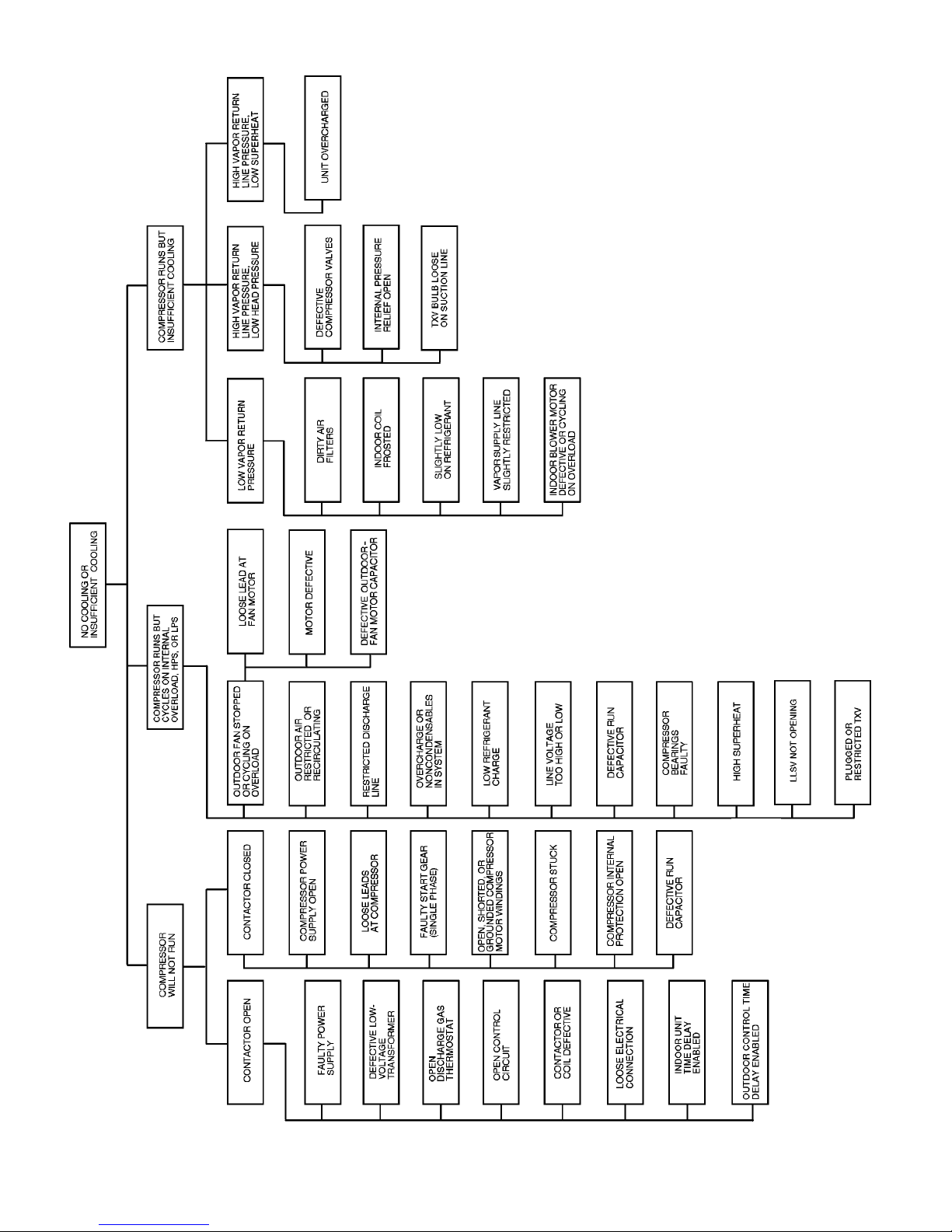
LEGEND
HPS — High-Pressure Switch
LLSV — Liquid (Vapor Supply) Line Solenoid Valve
LPS — Low-Pressure Switch
TXV — Thermostatic Expansion Valve
TROUBLESHOOTING CHART
—18—
Page 19

Page 20

Copyright 1996 Carrier Corporation CATALOG NO. BDP-3353-801
 Loading...