

Bryant 619B, 619F, 538S, 619C Installation, Start-up And Service Instructions Manual
IMPORTANT — READ BEFORE INSTALLING
1. Read and become familiar with these installation
instructions before installingthisunit (see Fig. 1 for typical multi-split system components).
2. Be sure the installation conforms to all applicable local
and national codes.
3. These instructions contain important information for the
proper maintenance and repair of this equipment. Retain these instructions for future use.
CONTENTS
Page
SAFETY CONSIDERATIONS ........................2
GENERAL .......................................2
I. System Description .........................2
II. Planning the System ........................2
INSTALLATION .................................2-13
I. Complete Pre-Installation Checks .............2
II. Install Outdoor Unit .........................4
III. Install Fan Coil Units ........................4
IV. Complete Refrigerant Piping ..................7
V. Make Electrical Connections .................8
START-UP ....................................13,14
I. Leak Test .................................13
II. Evacuate and Dehydrate ....................13
III. Charge System ............................13
IV. Preliminary Checks ........................13
V. Operating Sequence .......................13
SERVICE .....................................15-17
I. Outdoor Fan ..............................15
II. Scroll Compressors ........................15
III. High-Pressure Relief Valve ..................15
IV. Internal Current and Temperature Sensitive
Overload .................................15
V. High-Pressure Switch ......................15
VI. Low-Pressure Switch .......................15
VII. Service Valves ............................15
VIII. Refrigerant Charging .......................16
IX. Compressor Lockout Switch (CLO) ...........16
X. Outdoor-Coil Temperature Thermistor
(OCH TH) .................................17
XI. Low-Ambient Control Thermistor (LAT) .......17
XII. Pressure Transducer .......................17
MAINTENANCE .................................17
I. Lubrication ...............................17
II. Cleaning Coils ............................17
TROUBLESHOOTING ...........................17,18
I. Checking Cooling Control Operation ..........17
START-UP CHECKLIST ...................CL-1 to CL-4
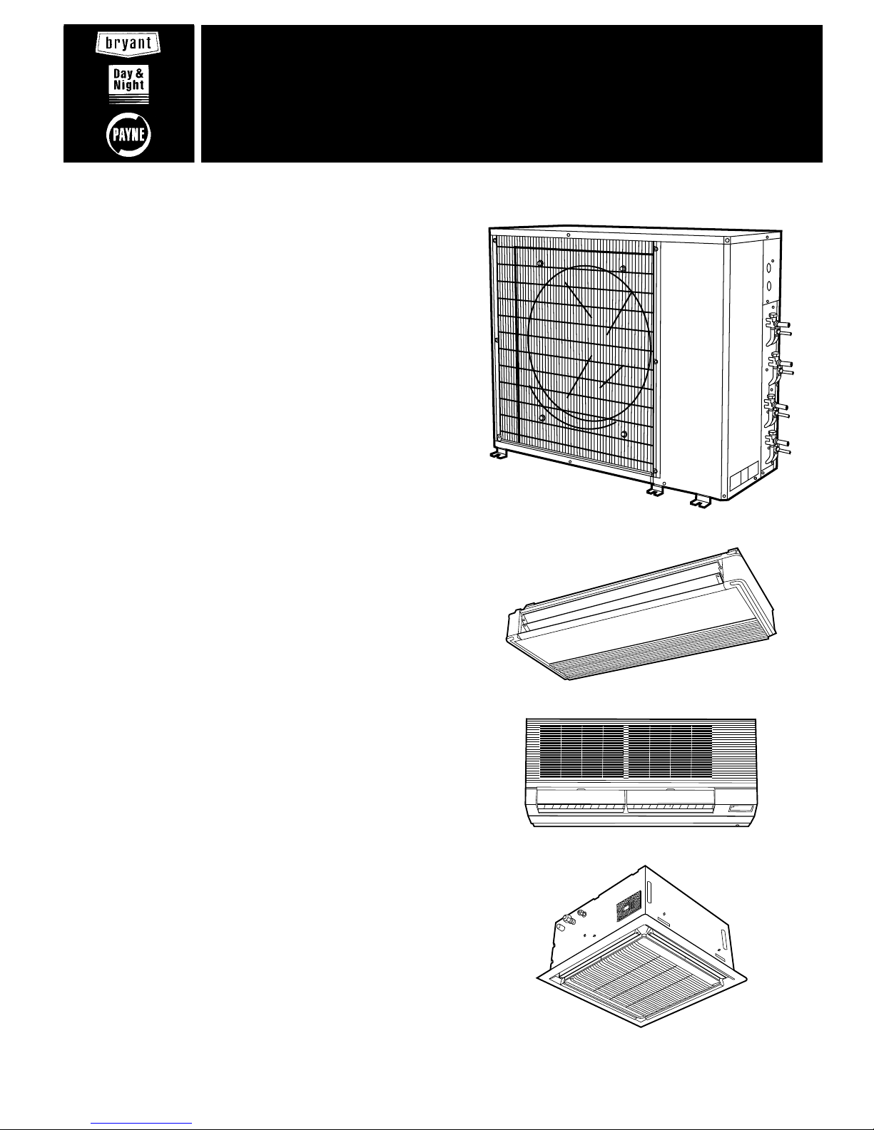
538S (048 Shown)
619C
619B
619F
Fig. 1 — Multi-Split System Components
installation, start-up and
service instructions
MULTI-SPLIT, DUCT-FREE
OUTDOOR COOLING UNITS
538S
Sizes 024,048
2 and 4 Tons
Cancels: New II 538S-24-1
2/15/96

SAFETY CONSIDERATIONS
Installing and servicing air-conditioning equipment can be hazardous due to system pressure and electrical components. Only
trained and qualified service personnel should install or service air-conditioning equipment.
Recognize safety information. This is the safety-alertsymbol
( ). When you see this symbol on the unit and in instructions or manuals, be alert to the potential for personal
injury.
Understand the signal words — DANGER, WARNING, and
CAUTION. These words are used with the safety-alert symbol. Danger identifies the most serious hazards which will
result in severe personal injury or death. Warning indicates
a situation that could result in personal injury. Caution is
used to identify unsafe practices which would result in minor
personal injury or product and property damage.
Untrained personnel can perform basic maintenance, such as
cleaning and replacing filters.All other operations should be
performed by trained service personnel. When working on airconditioning equipment, observe safety precautions in literature, and tags and labels attached to unit.
Follow all safety codes. Wear safety glasses and work gloves.
Use quenching cloth for brazing operations. Have fire extinguisher available. Read these instructions thoroughly. Consult local building codes and National Electrical Code (NEC)
Standard ANSI/NFPA 70 (American National Standards
Institute/National Fire Protection Association) for special installation requirements.
WARNING:
Before installing or servicing system, always turn off main power to system. There may be more
than one disconnect switch, since each fan coil unit will
normally have its own disconnect. Turn off accessory
heater power if applicable. Electrical shock can cause
personal injury.
GENERAL
IMPORTANT: Before installing a multi-split system, care-
fully read the following information:
• The TXV (thermostatic expansion valve) is located in the
outdoor unit, NOT the indoor fan coil units.
• The 538S outdoor unit has a factory-installed low-ambient
control which permits unit operation down to 0°F outdoor
ambient temperatures.
• BOTH refrigerant linesbetween the indoor and outdoor units
MUST BE insulated, because the TXV is in the outdoor
unit.
• If the installation includes a 619C ceiling-suspended fan
coil unit, REMOVE the AccuRatert device.
• DO NOT install a filter drier in the line set to the fan coil
units. A filter drier has already been factory-installed on
the outdoor unit.
• DO NOT run thermistor wires and control wires in the same
jacket.
• The 538S unit has been pre-charged at the factory with
sufficient refrigerant forthe entire system (assuming 25ft
of tubing and the use of one of the system combinations
listed in Planning the System section on this page).
I. SYSTEM DESCRIPTION
The 538S multi-split air conditioning system requires 3 major components (see Fig. 1):
• A 538S outdoor condensing unit
• Either 2, 3, or 4 duct-free split fan coil units for distribution of air to a maximum of 4 independent zones (see Planning the System section on this page)
• A wired or wireless infrared remote controller to control
each fan coil unit independently (one remote controller is
necessary for each fan coil unit)
NOTE: The remote controller is not available for 619F inceiling cassette fan coil units.
IMPORTANT: The 538S outdoor units may only be usedwith
the indoor fan coil unit sizes listed in Planning the System
section below. DO NOT try to substitute oradd more fan
coils to these systems.
II. PLANNING THE SYSTEM
This is a complex system with up to 4 separate tubing systems and 8 different control cable sets. Plan the installation
carefully as instructed below.Read these installation instructions (outdoor condensing unit) and the installation instructions included with each fan coil unit carefully and completely
PRIOR to system installation.
1. Maximum line length is 50 ft equivalent (any single line
run), and maximum elevation differential is 30 ft (from
highest to lowest system component).
2. Verify that components received form a legitimate multisplit system as follows:
a. Systems using one 538S_024 outdoor condensing unit
may use any combination (for a system total of 2 fan
coil units) of nominal 1
1
⁄2ton fan coil units.
b. Systems using one 538S_048 outdoor condensing unit
may use any of the following combinations:
• any combination (for a total of 2 fan coil units) of
nominal 2 ton fan coil units (1 fan coil unit per
circuit).
• any one nominal 2-ton fan coil unit on one circuit,
and any combination of 2 nominal 1
1
⁄2ton fan coil
units (for a system total of 3 fan coil units) on the
other circuit.
• any combination (for a system total of 4 fan coil
units) of nominal 1
1
⁄2ton fan coil units (2 fan coil
units per circuit).
3. Identify and record each fan coil section as it will be connected to the 538S outdoor unit on the Multi-Split
Installation Planning Worksheetincluded as part of the
Start-Up Checklist on page CL-1.
4. Check all system components to ensure that all required materials are on hand before starting installation of this system.
5. Re-read Installation section Step III — Install Fan Coil
Units, on page 4 before installing indoor fan coil units.
INSTALLATION
I. COMPLETE PRE-INSTALLATION CHECKS
A. Unpack Outdoor Unit (see Fig. 1)
Move 538S unit to final location. Remove carton from unit,
being careful not to damage service valves and grilles.
B. Inspect Shipment
File claim with shipping company if shipment is damaged or
incomplete. Check unit nameplate to be sure unit matches
job requirements.
C. Consider System Requirements
Consult local building codes and NEC for specialinstallation
requirements.
Allow sufficient space for airflow, wiring, refrigerant piping,
and servicing unit. See Fig. 2 and 3.
Locate unit so that condenser coil airflow is unrestricted on
both sides. Refer to Fig. 2 and 3.
—2—
UNIT
538S
_
ABCDEFGH
Ft-in. mm Ft-in. mm Ft-in. mm Ft-in. mm Ft-in. mm Ft-in. mm Ft-in. mm Ft-in. mm
024 2-1
1
⁄8638 3-015⁄
16
938 1-29⁄16370 1-4 406 1-117⁄16595 1-53⁄16437 1-51⁄2445 1-81⁄8511
048 3-1
3
⁄16945 3-89⁄
16
1132 1-51⁄16433 1-67⁄16468 2-61⁄
2
775 1-75⁄8499 2-55⁄8753 2-83⁄16818
UNIT
538S
_
J K L M N R S OPERATING WEIGHT
Ft-in. mm Ft-in. mm Ft-in. mm Ft-in. mm Ft-in. mm Ft-in. mm Ft-in. mm Lb Kg
024 1-2
7
⁄16367 0-63⁄4171 1-0 305 0-05⁄816 0-03⁄810 — — — — 159 72.0
048 1-2
3
⁄4375 0-71⁄2191 1-6 457 0-05⁄816 0-03⁄810 0-65⁄16160 0-57⁄8149 292 132.3
UNIT
538S
_
MINIMUM MOUNTING PAD DIMENSIONS
SUPPORT FEET SNOW STAND ICE STAND
Ft-in. mm Ft-in. mm Ft-in. mm
024 1-11 x 3-6 584 x 1067 2-2 x 3-6 660 x 1067 2-2 x 3-6 660 x 1067
048 2- 0 x 4-2 610 x 1270 2-4 x 4-4 711 x 1270 2-2 x 4-2 660 x 1270
NOTES:
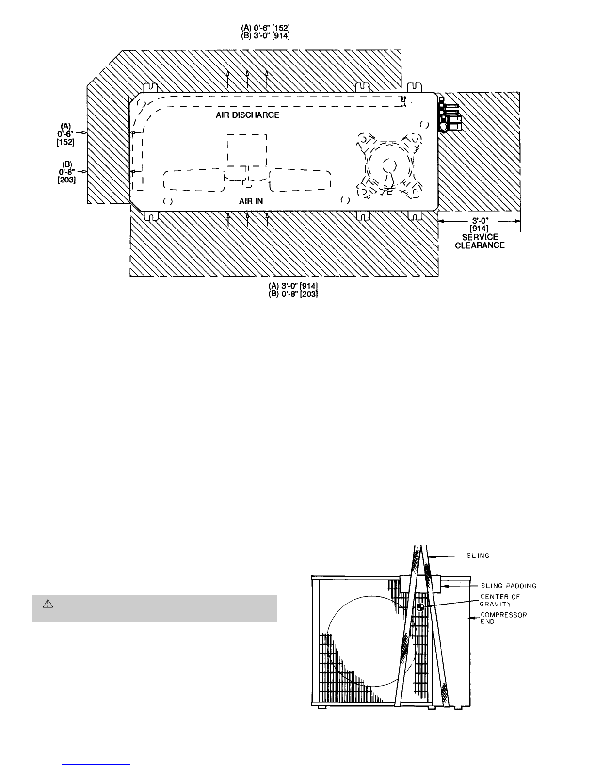
1. Required clearances: with coil facing wall; allow 6 in. minimum clearance on coil side and coil end, and 3 ft minimum clearance on compressor end and fan side. With fan facing wall; allow 8 in. minimum
clearance on fan side and coil end, and 3 ft minimum clearance on
compressor end and coil side. With multi-unit application: arrange
units so discharge of one does not enter inlet of another.
2. Dimensions in [ ] are in millimeters.
3. Center of gravity .
4. Thermistors are used with 619B and 619C fan coils only.
Fig. 2 — Base Unit Dimensional Drawing
—3—
Unit may be mounted on a level pad directly on base legs or
mounted on raised pads at support points. See Fig. 2 and 4
for center of gravity.
II. INSTALL OUTDOOR UNIT
A. Mounting on Ground
Mount unit on a solid, level concrete pad. Position unit so
water or ice from roof does not fall directly onto unit. If conditions or local codes require unit be fastened to pad, 6 fieldsupplied tiedown bolts should be used and fastened through
slots provided in unit mounting feet. See Fig. 2.
B. Mounting on Roof
Mount unit on a level platform or frame at least 6 in.
(154 mm) above roof surface. Isolate unit and tubing from
structure.
C. Surrounding Fences and Walls
Select and install surrounding fences and walls to allow for
free entry of ambient air. Avoid pits and solid walls as unit
surroundings, because recirculation of warm discharge air can
occur.
D. Rigging
CAUTION:
Be sure unit panels are securely in place
prior to rigging.
Keep unit upright. Lift unit using sling. Use cardboard or padding under sling, and use spreader bars to prevent sling damage to unit. See Fig. 4. See Fig. 2 and 4 for center of gravity
reference. Install unit so that coil does not face into prevailing winds. If this is not possible and constant winds above
25 mph are expected, field fabricate and install wind baffles.
In areas where outdoor ambient will be less than 40 F during
cooling, wind baffles are also required. Contact your local representative for drawings and assembly details.
III. INSTALL FAN COIL UNITS
Refer to Installation, Start-Up and Service Instructions provided with the fan coil units.
NOTE: If this system is mixing 2 or more types of fan coil
units, be sure to follow instructions provided with each type
of fan coil unit closely.
Mount fan coil units in locations which will be easily accessible when routing refrigerant tubing (see Fig. 5 and 6) and
electrical wiring between the fan coil unitsand outdoor unit.
Fan coil unit locations must also provide adequate drainage
capabilities. If desired, condensate pumps may be used with
any type of fan coil unit.
IMPORTANT: DO NOT install filter driers or AccuRatert re-
frigerant metering device body or pistons into this system.
TXVs are located in the outdoor condensing unit to control
refrigerant flow.
Fig. 4 — Lifting Unit With Sling
NOTE: Dimensions in [ ] are in mm.
(A) Minimum operating clearance required when this side faces a wall.
(B) Minimum operating clearance required when this side faces away from a wall.
Fig. 3 — Operating and Service Clearance
—4—
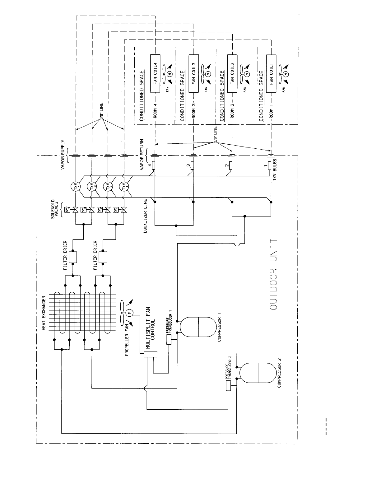
LEGEND
M—Motor
TXV — Thermostatic Expansion Valve
Field-Supplied Tubing
NOTE: Insulate ALL lines between outdoor condensing unit and indoor fan coil units.
Fig. 5 — Refrigerant Tubing Schematic (538S
_
048 Shown)
—5—
LEGEND
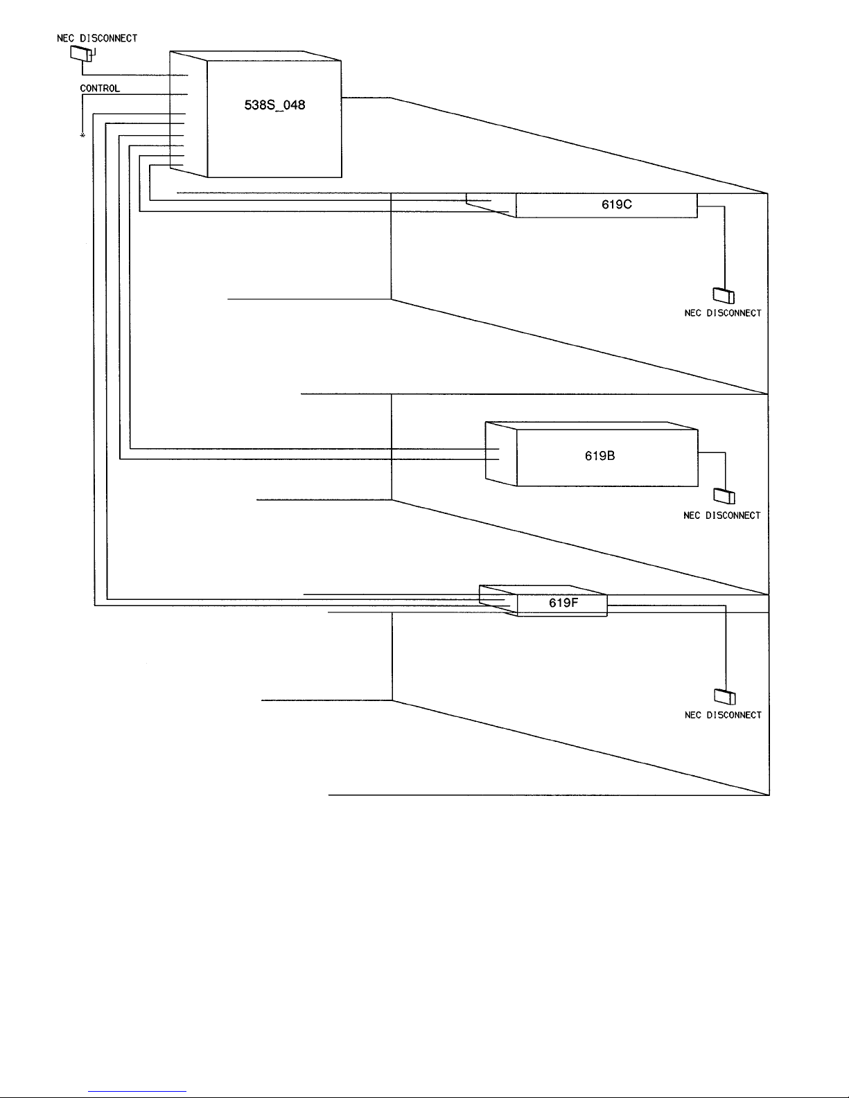
NEC — National Electrical Code
NOTE: Maximum system lift is 30 ft between lowest system compo-
nent and highest system component (see Fig. 7).
*See Connect Control Circuit Wiring section on page 9 for control
connection details.
Fig.6—Typical Piped System*
—6—
 Loading...