

Bryant 607C024, 607C030, 607C036, 607C042, 607C048 Installation Instructions Manual
...
607C
PREFERREDt 14 SEER
SINGLE--PACKAGED HEAT PUMP SYSTEM WITH PURONr
(R--410A) REFRIGERANT SINGLE AND THREE PHASE
NOMINAL 2--5 TONS (SIZES 024--060)
Installation Instructions
NOTE: Read the entire instruction manual before starting the
installation.
NOTE: Installer: Make sure the Owner’s Manual and Service
Instructions are left with the unit after installation.
TABLE OF CONTENTS
PAGE
SAFETY CONSIDERATIONS 1.........................
INTRODUCTION 2...................................
RECEIVING AND INSTALLATION 2--9..................
Check Equipment 2..................................
Identify Unit 2....................................
Inspect Shipment 2.................................
Provide Unit Support 2...............................
Roof Curb 2......................................
Slab Mount 2.....................................
Ground Mount 2..................................
Provide Clearances 2.................................
Rig and Place Unit 2.................................
Inspection 2......................................
Use of Rigging Bracket 3............................
Select and Install Ductwork 6...........................
Converting Horizontal Discharge Units to Downflow
(Vertical) Discharge Units 8..........................
Provide for Condensate Disposal 8......................
Install Electrical Connections 8.........................
High--Voltage Connections 8.........................
Special Procedures for 208--V Operation 9...............
Control Voltage Connections 9........................
Standard Connections 9.............................
Transformer Protection 9............................
Accessory Electric Heaters Installation 9................
607C Sequence of Operation 9........................
PRE--START--UP 15...................................
START--UP 15--17.....................................
Checking Cooling & Heating Control Operation 15........
Check for Refrigerant Leaks 15.........................
Start--Up Adjustments 15.............................
Checking & Adjusting Refrigerant Charge 16............
Indoor Airflow & Airflow Adjustments 16..............
Continuous Fan Operation 16........................
Defrost Control 17...................................
Quiet Shift 17.....................................
Defrost 17.......................................
MAINTENANCE 18--23................................
Air Filter 18........................................
Indoor Blower and Motor 18...........................
Outdoor Coil, Indoor Coil, & Condensate Drain Pan 20......
Outdoor Fan 21.....................................
Electrical Controls and Wiring 21.......................
Refrigerant Circuit 21.................................
Indoor Airflow 21...................................
Metering Devices-- TXV & Piston 21....................
Pressure Switches 22.................................
Loss of Charge Switch 22.............................
High Pressure Switch 22..............................
Copeland Scroll compressor (Puron Refrigerant) 22.........
TROUBLESHOOTING 23..............................
START-- UP CHECKLIST 23............................
Installation and servicing of this equipment can be hazardous due
to mechanical and electrical components. Only trained and
qualified personnel should install, repair, or service this equipment.
Untrained personnel can perform basic maintenance functions such
as cleaning and replacing air filters. All other operations must be
performed by trained service personnel. When working on this
equipment, observe precautions in the literature, on tags, and on
labels attached to or shipped with the unit and other safety
precautions that may apply.
Follow all safety codes. Installation must be in compliance with
local and national building codes. Wear safety glasses, protective
clothing, and work gloves. Have fire extinguisher available. Read
these instructions thoroughly and follow all warnings or cautions
included in literature and attached to the unit.
Recognize safety information. This is the safety--alert symbol
When you see this symbol on the unit and in instructions or manuals, be alert to the potential for personal injury. Understand these
signal words: DANGER, WARNING, and CAUTION. These
words are used with the safety--alert symbol. DANGER identifies
the most serious hazards which will result in severe personal injury
or death. WARNING signifies hazards which could result in per-
C99062
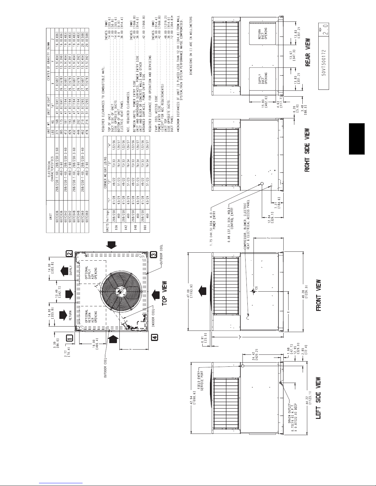
Fig. 1 -- Unit 607C
Refrigerant System 22................................
Refrigerant 22....................................
Compressor Oil 22.................................
Servicing Systems on Roofs with Synthetic Materials 22....
Liquid Line Filter Drier 23...........................
PuronR (R--410A) Refrigerant Charging 23.............
System Information 23................................
Loss of Charge Switch 23............................
Check Defrost Thermostat 23.........................
SAFETY CONSIDERATIONS
.
1
sonal injury or death. CAUTION is used to identify unsafe practices which may result in minor personal injury or product and property damage. NOTE is used to highlight suggestions which will
result in enhanced installation, reliability, or operation.
!
WARNING
ELECTRICAL SHOCK HAZARD
Failure to follow this warning could result in personal
injury or death.
Before installing or servicing system, always turn off main
power to system. There may be more than one disconnect
switch. Turn off accessory heater power switch if
applicable. TAG THE DISCONNECT SWITCH WITH A
SUITABLE WARNING LABEL.
!
WARNING
607C
FIRE, EXPLOSION, ELECTRICAL SHOCK AND
CARBON MONOXIDE POISONING HAZARD
Failure to follow this warning could result in personal
injury, death or property damage.
A qualified installer or agency must use only
factory--authorized kits or accessories when modifying this
product.
INTRODUCTION
The 607C heat pump is fully self-- contained and designed for
outdoor installation. (See Fig. 1) Standard units are shipped in a
horizontal--discharge configuration for installation on a
groundlevel slab. Standard units can be converted to downflow
(vertical) discharge configurations for rooftop applications.
RECEIVING AND INSTALLATION
Step 1 — Check Equipment
Identify Unit
The unit model number and serial number are stamped on the unit
identification plate. Check this information against shipping
papers.
Inspect Shipment
Inspect for shipping damage while unit is still on shipping pallet. If
unit appears to be damaged or is torn loose from its anchorage,
have it examined by transportation inspectors before removal.
Forward claim papers directly to transportation company.
Manufacturer is not responsible for any damage incurred in transit.
Check all items against shipping list. Immediately notify the
nearest equipment distributor if any item is missing. To prevent
loss or damage, leave all parts in original packages until
installation.
Step 2 — Provide Unit Support
Roof Curb
Install accessory roof curb in accordance with instructions shipped
with curb (See Fig. 5). Install insulation, cant strips, roofing, and
flashing. Ductwork must be attached to curb.
IMPORTANT: The gasketing of the unit to the roof curb is critical
for a watertight seal. Install gasketing material supplied with the
roof curb. Improperly applied gasketing also can result in air leaks
and poor unit performance.
Curb should be level to within 1/4 in. (6 mm) (See Fig. 6). This is
necessary for unit drain to function properly. Refer to accessory
roof curb installation instructions for additional information as
required.
Slab Mount
Place the unit on a solid, level concrete pad that is a minimum of 4
in. (102 mm) thick with 2 in. (51 mm) above grade (See Fig. 7).
The slab should extend approximately 2 in. (51 mm) beyond the
casing on all 4 sides of the unit. Do not secure the unit to the slab
except when required by local codes.
Ground Mount
The unit may be installed either on a slab or placed directly on the
ground if local codes permit. Place the unit on level ground
prepared with gravel for condensate discharge.
Step 3 — Provide Clearances
The required minimum service clearances are shown in Fig. 2 and
3. Adequate ventilation and outdoor air must be p rovided. The
outdoor fan draws air through the outdoor coil and discharges it
through the top fan grille. Be sure that the fan discharge does not
recirculate to the outdoor coil. Do not locate the unit in either a
corner or under an overhead obstruction. The minimum clearance
under a partial overhang (such as a normal house overhang) is 48
in. (1219 mm)above the unit top. The maximum horizontal
extension of a partial overhang must not exceed 48 in. (1219 mm).
IMPORTANT: Do not restrict outdoor airflow. An air restriction
at either the outdoor--air inlet or the fan discharge may be
detrimental to compressor life.
Do not place the unit where water, ice, or snow from an overhang
or roof will damage or flood the unit. Do not install the unit on
carpeting or other combustible materials. Slab--mounted units
should be at least 4 in. (102 mm) above the highest expected water
and runoff levels. Do not use unit if it has been under water.
Step 4 — Rig and Place Unit
Rigging and handling of this equipment can be hazardous for many
reasons due to the installation location (roofs, elevated structures,
etc.).
Only trained, qualified crane operators and ground support staff
should handle and install this equipment.
When working with this equipment, observe precautions in the
literature, on tags, stickers, and labels attached to the equipment, and
any other safety precautions that might apply.
Trainingforoperators of thelifting equipment should include,but not
be limited to, the following:
1. Application of the lifter to the load, and adjustment of the lifts
to adapt to various sizes or kinds of loads.
2. Instruction in any special operation or precaution.
3. Condition of the load as it relates to operation of the lifting kit,
such as balance, temperature, etc.
Follow all applicable safety codes. Wear safety shoes and work
gloves.
INSPECTION
The lifting/rigging bracket is engineered and designed to be installed
only on Small PackagedProducts.This bracket is to beused torig/lift
a Small Packaged Product onto roofs or other elevated structures.
Prior to initial use, and at monthly intervals, all rigging brackets and
straps should bevisually inspected for any damage,evidence of wear,
structural deformation, or cracks. Particular attention should be paid
to excessive wear at hoist hooking points and load support areas.
Brackets or straps showing any kind of wear in these areas must not
be used and should be discarded.
2
!
WARNING
!
WARNING
UNIT FALLING HAZARD
Failure to follow this warning could result in personal injury
or death.
Never stand beneath rigged units or lift over people.
!
PROPERTY DAMAGE HAZARD
Failure to follow this warning could result in personal
injury/death or property damage.
Rigging brackets for one unit use only. When removing a
unit at the end of its useful life, use a new set of brackets.
USE OF RIGGING BRACKET
WARNING
Field Installation of Rigging Bracket (if not already
installed)
1. Remove unit from shipping carton. Leave top shipping skid
on the unit for use as a spreader bar to prevent the rigging
straps from damaging the unit. If theskid is not available, use
a spreader bar of sufficient length to protect the unit from
damage.
2. Remove 4 screws in unit corner posts.
3. Attach each of the 4 metal rigging brackets under the panel
rain lip. Use the screws removed in step 2 aboveto securethe
brackets to the unit.
PROPERTY DAMAGE HAZARD
Failure to follow this warning could result in personal
injury/death or property damage.
Rigging bracket MUST be under the rain lip to provide
adequate lifting.
!
PROPERTY DAMAGE HAZARD
Failure to follow this warning could result in personal
injury/death or property damage.
Do not strip screws when re--securing the unit. If a screw is
stripped, replace the stripped one with a larger diameter screw
(included). When straps are taut, the clevis should be a
minimum of 36 in. (914 mm) above the unit top cover.
WARNING
Rigging/Lifting of Unit
1. Bend top of bracketsdown approximately 30 degrees from the
corner posts.
2. Attach straps of equal length to the rigging brackets at
opposite ends of the unit. Be sure straps are rated to hold the
weight of the unit.
3. Attach a clevisof sufficient strengthin the middleof the straps.
Adjust the clevis location to ensure unit is lifted level with the
ground.
4. Remove corner post screws and rigging brackets, then
re--install screws.
After the unit is placed on the roof curb or mounting pad, removethe
top crating.
607C
3
607C
A08084
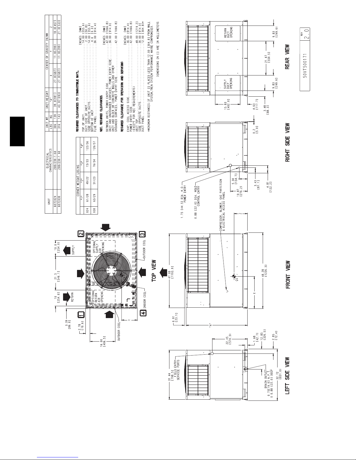
Fig. 2 -- 607C024--030 Unit Dimensions
4
607C
A08085
Fig. 3 -- 607C036--060 Unit Dimensions
5
12
DETAIL A
(914 mm)
RIGGING WEIGHTS (SMALL CABINET) RIGGING WEIGHTS (LARGE CABINET)
607C
Unit
Shipping
Weight
Rigging
Weight
* For 460 volt units, add 14 lb (6.4 kg) to the weight.
024 030 036*
lb kg lb kg lb kg lb kg lb kg lb kg
354 171 364 165 419 190
317 144 327 148 382 173
Step 5 — Select and Install Ductwork
The design and installation of the duct system must be in
accordance with the standards of the NFPA for installation of
non--residence type air conditioning and ventilating systems,
NFPA 90A or residence--type, NFPA 90B and/or local codes and
ordinances.
Select and size ductwork, supply--air registers, and return air grilles
according to ASHRAE (American Society of Heating,
Refrigeration, and Air Conditioning Engineers) recommendations.
The unit has duct flanges on the supply-- and return--air openings
on the side of the unit.
!
WARNING
PERSONAL INJURY HAZARD
Failure to follow this warning could result in personal
injury or death.
For vertical supply and return units, tools or parts could
drop into ductwork Install a 90 degree turn in the return
ductwork between the unit and the conditioned space. If a
90 degree elbow cannot be installed, then a grille of
sufficient strength and density should be installed to prevent
objects from falling into the conditioned space. Units with
electric heaters require 90 degree elbow in supply duct.
34
A08015
Unit
Shipping
Weight
Rigging
Weight
Fig. 4 -- Rigging Weights
When designing and installing ductwork, consider the following:
1. All units should have field--supplied filters or accessory
filter rack installed in the return--air side of the unit.
Recommended sizes for filters are shown in Table 1.
2. Avoid abrupt duct size increases and reductions. Abrupt
change in duct size adversely affects air performance.
IMPORTANT: Use flexible connectors between ductwork and
unit to prevent transmission of vibration. Use suitable gaskets to
ensure weather tight and airtight seal. When electric heat is
installed, use fireproof canvas (or similar heat resistant material)
connector between ductwork and unit discharge connection. If
flexible duct is used, insert a sheet metal sleeve inside duct. Heat
resistant duct connector (or sheet metal sleeve) must extend 24--in.
(610 mm) from electric heater element.
3. Size ductwork for cooling air quantity (cfm). The minimum
air quantity for proper electric heater operation is listed in
Table 2. Heater limit switches may trip at air quantities
below those recommended.
4. Seal, insulate, and weatherproof all external ductwork. Seal,
insulate and cover with a vapor barrier all ductwork passing
through conditioned spaces. Follow latest Sheet Metal and
Air Conditioning Contractors National Association
(SMACNA) and Air Conditioning Contractors Association
(ACCA) minimum installation standards for residential
heating and air conditioning systems.
5. Secure all ducts to building structure. Flash, weatherproof,
and vibration--isolate duct openings in wall or roof
according to good construction practices.
A08005
042* 048* 060*
464 210 484 220 514 233
427 164 447 203 477 216
6
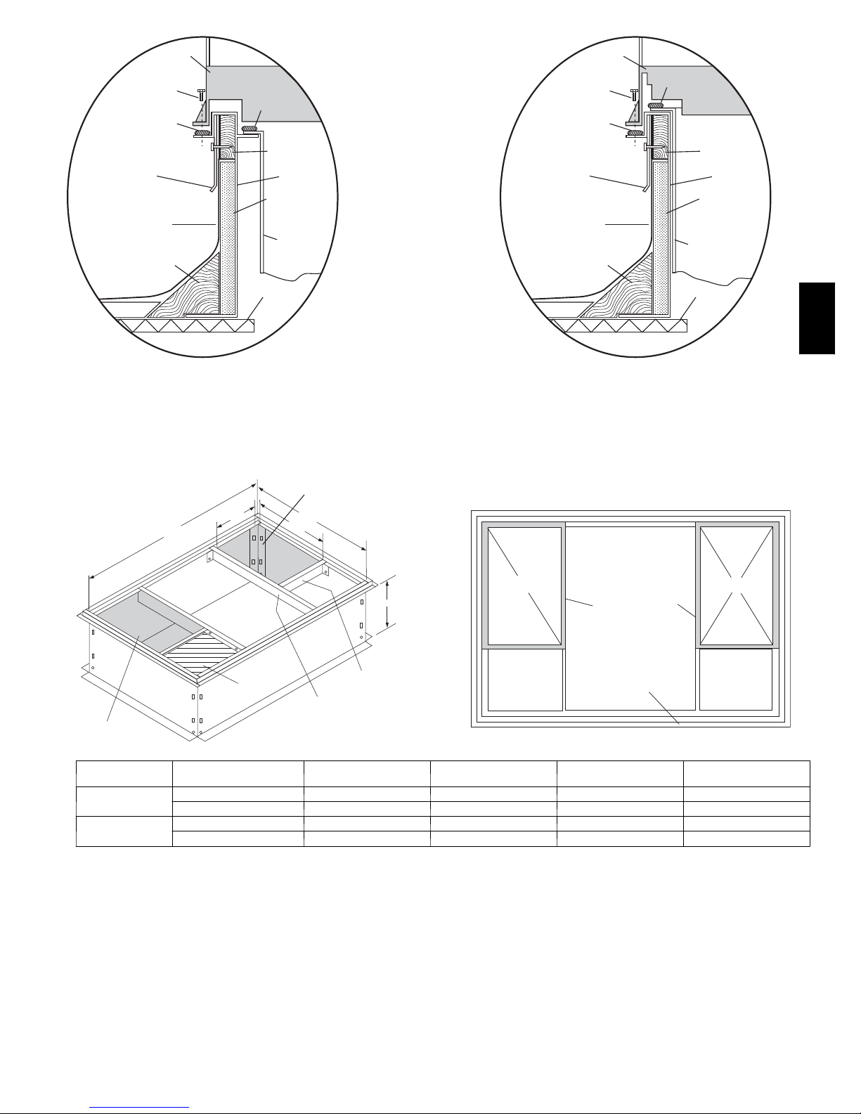
HVAC unit
Scre w
(NO TE A)
*Gask eting
outer flange
Flashing field
supplied
Roofing material
field supplied
Cant str ip
field supplied
base
Gask eting
inner flange*
Wood nailer*
Roofcurb*
Insulation (field
supplied)
Duct wo
field supplied
HVAC unit
base
Scre w
(NOTE A)
*Gask eting
outer flange
Flashing field
supplied
Roofing material
field supplied
rk
Cant str ip
field supplied
Gask eting
inner flange*
Duct wo rk
field supplied
Wood nailer*
Roofcurb*
Insulation (field
supplied)
Roof
*Provided with roofcurb
Roof Curb for Small Cabinet
Note A: When unit mounting scre w is used,
retainer must also be used.
bracket
Supply opening
(B x C)
Return opening
(B X C)
UNIT SIZE
607C024-- 030
607C036-- 060
B Typ.
5
44
/
16
"
(1126 mm)
d
Insulate
deck pan
CATALOG
NUMBER
CPRFCURB006A00 8 (203) 11 (279) 16--1/2 (419) 28--3/4 (730)
CPRFCURB007A00 14 (356) 11 (279) 16--1/2 (419) 28--3/4 (730)
CPRFCURB008A00 8 (203) 16--3/16 (411) 17--3/8 (441) 40--1/4 (1022)
CPRFCURB009A00 14 (356) 16--3/16 (411) 17--3/8 (441) 40--1/4 (1022)
C Typ .
D
Long
Support
Short
Support
A
IN. (MM)
A
NOTES:
1. Roof curb must be set up for unit being installed.
2. Seal strip must be applied, as required, to unit being installed.
4. Dimension in ( ) are in millimeters.
5. Roof curb is made of 16---gauge steel.
6. Attach ductwork to curb (flanges of duct rest on curb).
7. Insu lated panels: 1- --in. (25 mm) thick fiberglass 1 lb. den sity.
8. When unit mounting screw is used (see Note A), a retainer bracket must
be used as well. This bracket must also be used when required by code for
hurricane or seismic conditions. This bracket is available through Micrometl.
Fig. 5 -- Roof Curb Dimensions
Insulated
deck pan
B
IN. (MM)
*Provided with roofcurb
Roof Curb for
Note A: When unit mounting scre w is used,
retainer bra cket must also be used.
Large Cabinet
R/A
Gask et around
duct
Gask et around
outer edge
C
IN. (MM)
Roof
S/A
D
IN. (MM)
607C
C00076
7
A
C
MAXIMUM ALLOWABLE
B
A-B
(6.35)
1/4
DIFFERENCE in. (mm)
B-C
(6.35)
1/4
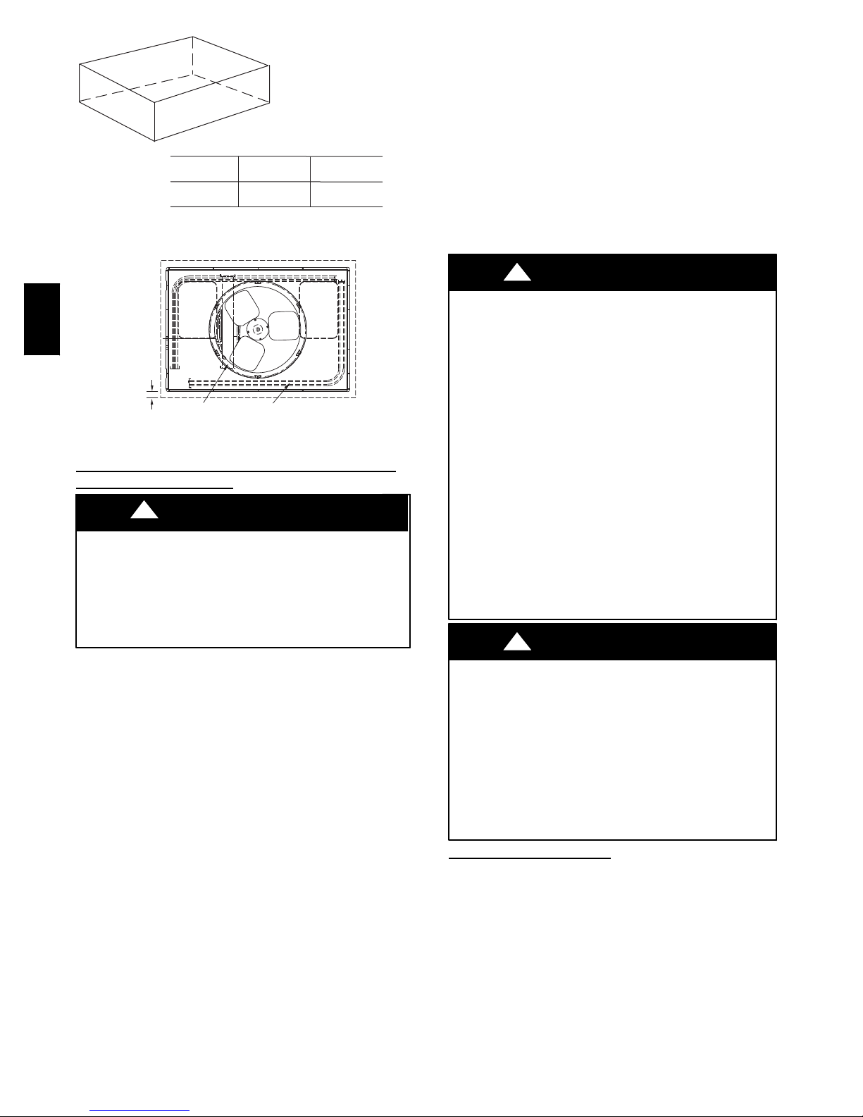
Fig. 6 -- Unit Leveling Tolerances
1/4
A-C
(6.35)
A07925
If the installation requires draining the condensate water away from
the unit, install a field--supplied 2 --in. (51mm) trap at the
condensate connection to ensure proper drainage. Condensate trap
is available as an accessory or is field--supplied. Make sure that the
outlet of the trap is at least 1 in. (25 mm) lower than the unit
drain--pan condensate connection to prevent the pan from
overflowing. Connect a drain trough using a minimum of
field--supplied 3/4--in. PVC or field--supplied 3/4--in. copper pipe
at outlet end of the 2--in. (51 mm) trap. (See Fig. 11) Do not
undersize the tube. Pitch the drain trough downward at a slope of at
least 1 in. (25 mm) every 10 ft (3 m) of horizontal run. Be sure to
check the drain trough for leaks. Prime the trap at the beginning of
the cooling season start--up.
Step 7 — Install Electrical Connections
607C
2˝
(50.8mm)
OPTIONAL
RETURN
AIR
OPENING
OPTIONAL
SUPPLY
AIR
OPENING
!
UNIT COMPONENT DAMAGE HAZARD
Failure to follow this caution may result in damage to the unit
being installed.
1. Make all electrical connections in accordance with NEC
NFPA 70 (latest edition) and local electrical codes
CAUTION
governing such wiring. In Canada, all electrical
EVAP. COIL COND. COIL
A07926
Fig. 7 -- Slab Mounting Detail
connections must be in accordance with CSA standard
C22.1 Canadian Electrical Code Part 1 and applicable
local codes. Refer to unit wiring diagram.
2. Use only copper conductor for connections between
Converting Horizontal Discharge Units to Downflow
(vertical) Discharge
Units
field--supplied electrical disconnect switch and unit. DO
NOT USE ALUMINUM WIRE.
3. Be sure that high-- voltage power to unit is within
!
WARNING
ELECTRICAL SHOCK HAZARD
Failure to follow this warning could result in personal injury
or death.
Before installing or servicing system, always turn off main
power to system. There may be more than one disconnect
operating voltage range indicated on unit rating plate. On
3--phase units, ensure phases are balanced within 2
percent. Consult local power company for correction of
improper voltage and/or phase imbalance.
4. Do not damage internal components when drilling
through any panel to mount electrical hardware, conduit,
etc.
switch. Tag the disconnect switch with a suitable warning
label.
1. Open all electrical disconnects before starting any service
work.
2. Remove horizontal duct covers to access bottom return and
supply knock out panels.
3. Use a screwdriver and hammer to remove the panels in the
bottom of the unit base.
NOTE: These panels are held in place with tabs similar to an
electrical knockout.
4. Reinstall the horizontal duct covers (Fig. 10) to block off
the horizontal air openings.
NOTE: Avoid abrupt duct size increases and reductions. Abrupt
ELECTRICAL SHOCK HAZARD
Failure to follow this warning could result in personal injury
or death.
The unit cabinet must have an uninterrupted, unbroken
electrical ground. This ground may consist of an electrical
wire connected to the unit ground screw in the control
compartment, or conduitapprovedfor electrical ground when
installed in accordance with NEC,NFPA 70 National Fire
Protection Association (latest edition) (in Canada, Canadian
Electrical Code CSA C22.1) and local electrical codes.
!
WARNING
change in duct size adversely affects air performance.
Step 6 — Provide for Condensate Disposal
NOTE: Ensure that condensate--water disposal methods comply
with local codes, restrictions, and practices.
The 607C units dispose of condensate through a 3/4 in. NPT
female fitting that exits on the compressor end of the unit.
Condensate water can be drained directly onto the roof in rooftop
installations (where permitted) or onto a gravel apron in ground
level installations. Install a field--supplied condensate trap at end of
condensate connection to ensure proper drainage. Make sure that
the outlet of the trap is at least 1 in. (25 mm) lower than the
drain--pan condensate connection to prevent the pan from
overflowing. Prime the trap with water. When using a gravel apron,
make sure it slopes away from the unit.
High--Voltage Connections
The unit must have a separate electrical service with a
field--supplied, waterproof disconnect switch mounted at, or within
sight from the unit. Refer to the unit rating plate, NEC and local
codes for maximum fuse/circuit breaker size and minimum circuit
amps (ampacity) for wire sizing.
The field--supplied disconnect may be mounted on the unit over
the high--voltage inlet hole when the standard power and
low--voltage entry points are used. See Fig. 2 and 3 for acceptable
location. Remove high voltage knockout.
See unit wiring label (Fig. 12--14) and Fig. 8 for reference when
making high voltage connections. Proceed as follows to complete
the high--voltage connections to the unit.
8
 Loading...