

Bryant 604B 024–060, 604B024, 604B036, 604B030, 604B042 Installation, Start-up And Service Instructions Manual
...
Installation, Start-Up,
and Service Instructions
604B 024–060
SINGLE-PACKAGED HEAT PUMP UNITS
WITH PURON® (R-410A) REFRIGERANT
Cancels: II 604B.24.2 II 604B.24.3
12–03
NOTE: Read the entire instruction manual before starting the
installation.
This symbol → indicates a change since the last issue.
TABLE OF CONTENTS
SAFETY CONSIDERATIONS.....................................................1
Introduction ....................................................................................2
Receiving and Installation..............................................................2
Check Equipment......................................................................2
IDENTIFY UNIT................................................................2
INSPECT SHIPMENT........................................................2
Provide Unit Support................................................................2
ROOF CURB.......................................................................2
SLAB MOUNT ...................................................................2
GROUND MOUNT ............................................................2
Provide Clearances....................................................................2
Rig and Place Unit....................................................................2
INSPECTION......................................................................3
INSTALLATION ................................................................3
Select and Install Ductwork .....................................................5
CONVERTING HORIZONTAL DISCHARGE UNITS TO
DOWNFLOW (VERTICAL) DISCHARGE UNITS.........7
Provide for Condensate Disposal.............................................7
Install Electrical Connections...................................................8
HIGH-VOLTAGE CONNECTIONS..................................9
ROUTING POWER LEADS INTO UNIT........................9
CONNECTING GROUND LEAD TO GROUND LUG ..9
ROUTING CONTROL POWER WIRES (24-V)..............9
Easy Select™—604B........................................................10
604B Sequence Of Operation ...........................................17
SPECIAL PROCEDURES FOR 208-V OPERATION ...17
PRE-START-UP ..........................................................................18
START-UP...................................................................................18
604B: Start-Up........................................................................18
Check for Refrigerant Leaks..................................................19
Start-Up Adjustments..............................................................19
CHECKING COOLING AND HEATING CONTROL OP-
ERATION..........................................................................19
CHECKING AND ADJUSTING REFRIGERANT
CHARGE...........................................................................19
REFRIGERANT CHARGE..............................................20
NO CHARGE....................................................................20
LOW CHARGE COOLING .............................................20
TO USE COOLING CHARGING CHARTS ..................20
INDOOR AIRFLOW AND AIRFLOW ADJUST-
MENTS..............................................................................21
Defrost Control .......................................................................21
Quiet Shift..........................................................................21
Defrost................................................................................22
MAINTENANCE.........................................................................23
Air Filter..................................................................................24
Indoor Blower and Motor.......................................................24
Outdoor Coil, Indoor Coil, and Condensate Drain Pan........24
Outdoor Fan............................................................................24
Electrical Controls and Wiring...............................................25
Refrigerant Circuit..................................................................25
Indoor Airflow........................................................................25
Metering Devices–TXV & Accurater Piston.........................25
Pressure Switches....................................................................25
Loss of Charge Switch ...........................................................25
High-Pressure Switch..............................................................25
Copeland Scroll Compressor (Puron Refrigerant).................25
Refrigerant System..................................................................26
Refrigerant .........................................................................26
Compressor Oil..................................................................26
Servicing Systems on Roofs with Synthetic Materials....26
Liquid Line Filter Drier ....................................................26
Puron (R-410A) Refrigerant Charging .............................26
System Information.................................................................26
Loss of Charge Switch......................................................26
Check Defrost Thermostat ................................................26
TROUBLESHOOTING ...............................................................26
Start-Up Checklist........................................................................26
NOTE TO INSTALLER — READ THESE INSTRUCTIONS
CAREFULLY AND COMPLETELY before installing this unit.
Also, make sure the Owner’s Manual and Service Instructions are
left with the unit after installation.
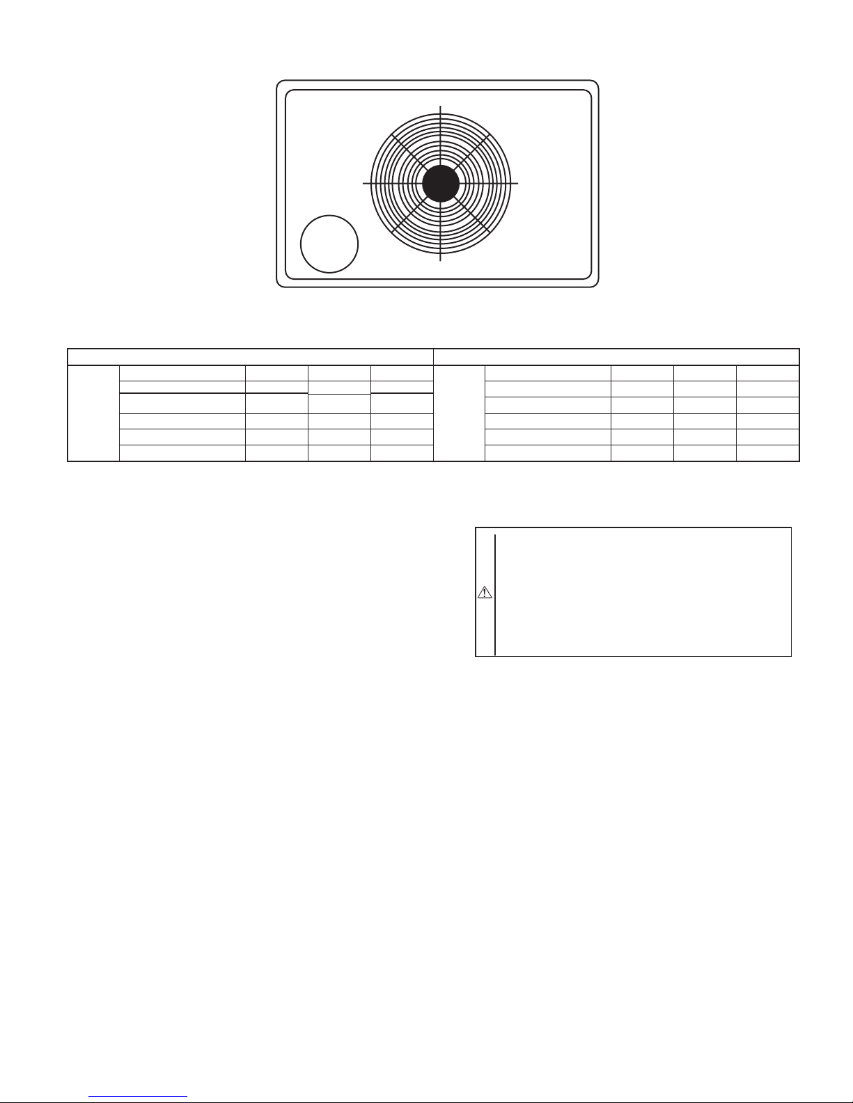
C99064
Fig. 1—Unit 604B
SAFETY CONSIDERATIONS
Installation and servicing of air-conditioning equipment can be
hazardous due to system pressure and electrical components. Only
trained and qualified personnel should install, repair, or service
air-conditioning equipment.
—1—
Untrained personnel can perform basic maintenance functions of
cleaning coils and filters. All other operations should be performed
by trained service personnel. When working on air-conditioning
equipment, observe precautions in the literature, tags, and labels
attached to the unit, and other safety precautions that may apply.
Follow all safety codes. Wear safety glasses and work gloves. Use
quenching cloth for unbrazing operations. Have fire extinguisher
available for all brazing operations.
WARNING: Improper installation, adjustment, alteration, service, maintenance, or use can cause explosion,
fire, electric shock, or other occurrences, which could
cause serious injury or death or damage your property.
Consult a qualified installer or service agency for information or assistance. The qualified installer or agency
must use only factory-authorized kits or accessories when
modifying this product.
Recognize safety information. This is the safety-alert symbol .
When you see this symbol on the product or in instructions or
manuals, be alert to the potential for personal injury.
Understand the signal words — DANGER, WARNING, CAUTION, and NOTE. Danger identifies the most serious hazards,
which will result in severe personal injury or death. Warning
indicates a condition that could cause serious personal injury or
death. Caution is used to identify unsafe practices, which would
result in minor personal injury or product and property damage.
NOTE is used to highlight suggestions which will result in
enhanced installation, reliability, or operation.
1. The power supply (volts, phase, and hertz) must correspond
to that specified on unit rating plate.
2. The electrical supply provided by the utility must be
sufficient to handle load imposed by this unit.
3. This installation must conform with local building codes
and with NEC (National Electrical Code). Refer to provincial and local plumbing or waste water codes and other
applicable local codes.
WARNING: Before performing service or maintenance
operations on system, turn off main power to unit. Turn
off accessory heater power switch if applicable. Electrical
shock could cause severe injury or death.
CAUTION: Puron (R-410A) systems operate at higher
pressures than standard R-22 systems. DO not use R-22
service equipment or components on Puron (R-410A)
equipment. Ensure service equipment is rated for Puron
(R-410A)
INTRODUCTION
The 604B heat pump is fully self-contained and designed for
outdoor installation. (See Fig. 1) Standard units are shipped in a
horizontal-discharge configuration for installation on a groundlevel slab. Standard units can be converted to downflow (vertical)
discharge configurations for rooftop applications.
RECEIVING AND INSTALLATION
I. CHECK EQUIPMENT
A. IDENTIFY UNIT
The unit model number and serial number are stamped on the unit
identification plate. Check this information against shipping papers.
B. INSPECT SHIPMENT
Inspect for shipping damage while unit is still on shipping pallet.
If unit appears to be damaged or is torn loose from its anchorage,
have it examined by transportation inspectors before removal.
Forward claim papers directly to transportation company. Manufacturer is not responsible for any damage incurred in transit.
Check all items against shipping list. Immediately notify the
nearest Bryant Air Conditioning office if any item is missing. To
prevent loss or damage, leave all parts in original packages until
installation.
II. PROVIDE UNIT SUPPORT
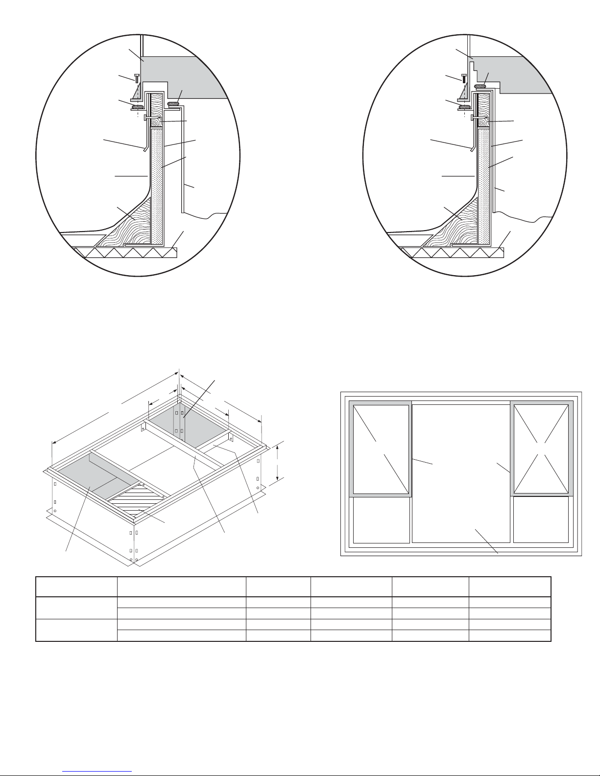
A. ROOF CURB
Install accessory roof curb in accordance with instructions shipped
with curb (See Fig. 5). Install insulation, cant strips, roofing, and
flashing. Ductwork must be attached to curb.
IMPORTANT: The gasketing of the unit to the roof curb is
critical for a watertight seal. Install gasketing material supplied
with the roof curb. Improperly applied gasketing also can result in
air leaks and poor unit performance.
Curb should be level to within 1/4 in. (See Fig. 6). This is
necessary for unit drain to function properly. Refer to accessory
roof curb installation instructions for additional information as
required.
B. SLAB MOUNT
Place the unit on a solid, level concrete pad that is a minimum of
4 in. thick with 2 in. above grade (See Fig. 7). The slab should
extend approximately 2 in. beyond the casing on all 4 sides of the
unit. Do not secure the unit to the slab except when required by
local codes.
C. GROUND MOUNT
The unit may be installed either on a slab or placed directly on the
ground if local codes permit. Place the unit on level ground
prepared with gravel for condensate discharge.
III. PROVIDE CLEARANCES
The required minimum service clearances are shown in Figs. 2 and
3. Adequate ventilation and outdoor air must be provided. The
outdoor fan draws air through the outdoor coil and discharges it
through the top fan grill. Be sure that the fan discharge does not
recirculate to the outdoor coil. Do not locate the unit in either a
corner or under an overhead obstruction. The minimum clearance
under a partial overhang (such as a normal house overhang) is 48
in. above the unit top. The maximum horizontal extension of a
partial overhang must not exceed 48 in.
IMPORTANT: Do not restrict outdoor airflow. An air restriction
at either the outdoor-air inlet or the fan discharge may be
detrimental to compressor life.
Do not place the unit where water, ice, or snow from an overhang
or roof will damage or flood the unit. Do not install the unit on
carpeting or other combustible materials. Slab-mounted units
should be at least 4 in. above the highest expected water and runoff
levels. Do not use unit if it has been under water.
IV. RIG AND PLACE UNIT
Rigging and handling of this equipment can be hazardous for many
reasons due to the installation location (roofs, elevated structures,
etc.)
Only trained, qualified crane operators and ground support staff
should handle and install this equipment.
When working with this equipment, observe precautions in the
literature, on tags, stickers, and labels attached to the equipment,
and any other safety precautions that might apply.
Follow all applicable safety codes. Wear safety shoes and work
gloves.
—2—
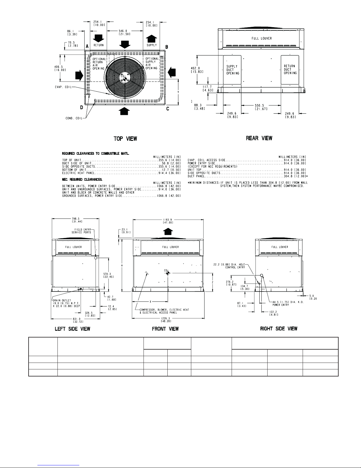
Required Clearance for Operation and Service
UNIT ELECTRICAL CHARACTERISTICS
604B024 208/230-1-60 350 159 39.02 (991.1) 20.0 (508.0) 19.3 (489.0) 17.6 (447.0)
604B030 208/230-1-60 350 159 39.02 (991.1) 20.0 (508.0) 19.3 (489.0) 17.6 (447.0)
604B036 208/230-1-60,208/230-3-60 373 169 41.02 (1041.9) 20.0 (508.0) 14.0 (355.6) 13.0 (330.2)
A. INSPECTION
Prior to initial use, and at monthly intervals, all rigging brackets
and straps should be visually inspected for any damage, evidence
of wear, structural deformation, or cracks. Particular attention
should be paid to excessive wear at hoist hooking points and load
support areas. Brackets or straps showing any kind of wear in these
areas must not be used and should be discarded.
UNIT WEIGHT
lb kg X Y Z
UNIT HEIGHT
IN. (MM)
”A”
Fig. 2—604B024-036 Unit Dimensions
B. INSTALLATION
1. Remove unit from shipping carton. Leave top shipping skid
on the unit as a spreader bar to prevent the rigging straps
from damaging the unit. If the wood skid is not available,
use a spreader bar of sufficient length to protect unit from
damage.
—3—
C00160
CENTER OF GRAVITY
IN. (MM)
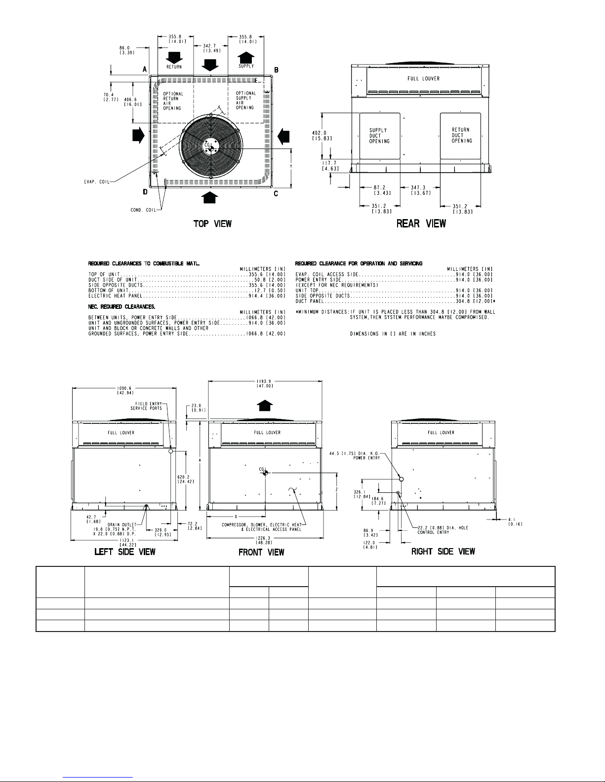
UNIT ELECTRICAL CHARACTERISTICS
604B042 208/230-1-60, 208/230-3-60 440 200 42.98 (1091.7) 21 (533.4) 20.5 (520.7) 16.6 (421.6)
604B048 208/230-1-60, 208/230-3-60 463 210 44.98 (1142.5) 19.5 (495.3) 21.3 (539.8) 18.0 (457.2)
604B060 208/230-1-60, 208/230-3-60 499 226 46.98 (1193.3) 21.0 (533.4) 20.0 (508.0) 17.6 (442.0)
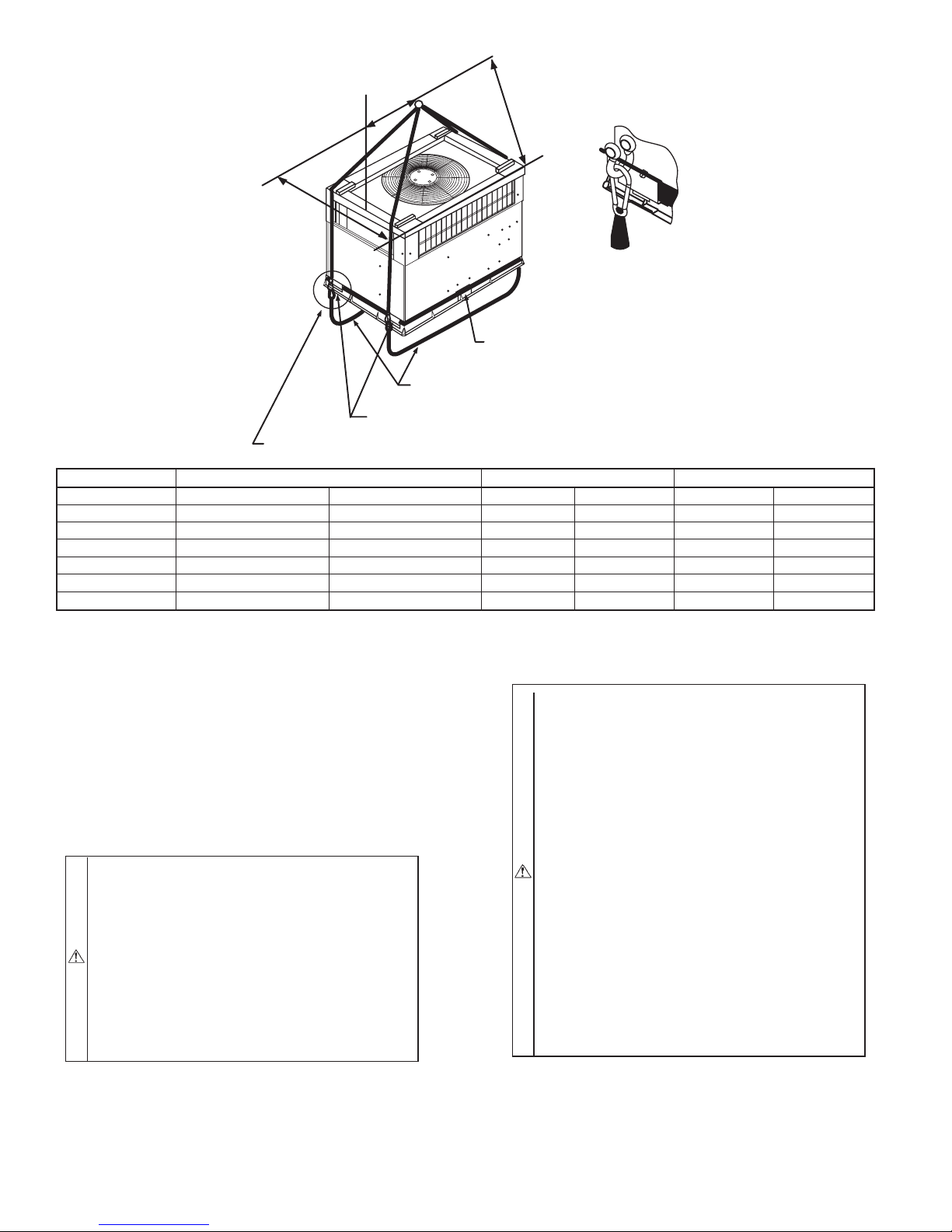
2. Position the lifting bracket assembly around the base of the
unit. Be sure the strap does not twist.
3. Place each of the 4 metal lifting brackets into the rigging
holds in the composite unit base.
4. Thread lifting bracket strapping around bottom perimeter of
unit as follows:
a. Open lever of tension buckle (ratchet type).
b. Feed strapping through tension buckle as shown in Fig.
8.
UNIT WEIGHT
lb kg X Y Z
UNIT HEIGHT
IN. (MM)
”A”
Fig. 3—604B 042-060 Unit Dimensions
c. Pull strapping through tension buckle unit taut.
d. Snap lever down to lock strap in tension buckle. To
release strapping, squeeze safety latch, lift lever, and pull
webbing outward.
5. Tighten the tension buckle until it is taut. Lifting brackets
must be secure in the rigging holds.
6. Attach field-supplied clevis or hook of sufficient strength to
hole in the lifting bracket. (See Fig. 9)
—4—
C00161
CENTER OF GRAVITY
IN. (MM)
12
y
43
CORNER WEIGHTS (SMALL CABINET) CORNER WEIGHTS (LARGE CABINET)
Unit 24 30 36
Total Weight 350 350 373 Total Weight 440 463 499
Corner Weight 1 70 70 75 Corner Weight 1 88 98 107
Corner Weight 2 54 54 58 Corner Weight 2 68 61 70
Model 604B
7. Attach the 2 safety straps directly to the clevis or hook at the
8. Position lifting point directly over the unit’s center of
9. Lift unit. When unit is directly over the roof curb, remove
10. After the unit is placed on the roof curb or mounting pad,
V. SELECT AND INSTALL DUCTWORK
The design and installation of the duct system must be in
accordance with the standards of the NFPA for installation of
non-residence type air conditioning and ventilating systems, NFPA
90A or residence-type, NFPA 90B and/or local codes and ordinances.
Select and size ductwork, supply-air registers, and return air grilles
according to ASHRAE (American Society of Heating, Refrigeration, and Air Conditioning Engineers) recommendations.
The unit has duct flanges on the supply- and return-air openings on
the side of the unit.
When designing and installing ductwork, consider the following:
Corner Weight 3 84 84 90 Corner Weight 3 106 127 136
Corner Weight 4 141 141 150 Corner Weight 4 177 177 186
Fig. 4—Corner Weights
4 rigging brackets. DO NOT attach the safety straps to the
lifting brackets. (See Fig. 9)
gravity.
the 2 safety straps. Lower the equipment onto the roof curb.
remove the top crating. On 604B060 units only, 2 wire ties
fastened to the outdoor coils and reversing
valve/accumulator assembly must be cut. Remove the left
and front louver panels and corner post to access wire ties.
The wire tie to be cut on the left is located approximately 4
in. down the tube sheet. The wire tie to be cut on the right
is located approximately 6 in. down the tube sheet.
x
C00071
Unit 42 48 60
Model 604B
WARNING: For vertical supply and return units, tools
or parts could drop into ductwork and cause serious injury
or death. Install a 90 degree turn in the return ductwork
between the unit and the conditioned space. If a 90 degree
elbow cannot be installed, then a grille of sufficient
strength and density should be installed to prevent objects
from falling into the conditioned space. Units with
electric heaters require 90 degree elbow in supply duct.
1. All units should have field-supplied filters or accessory
filter rack installed in the return-air side of the unit.
Recommended sizes for filters are shown in Table 1.
2. Avoid abrupt duct size increases and reductions. Abrupt
change in duct size adversely affects air performance.
IMPORTANT: Use flexible connectors between ductwork and
unit to prevent transmission of vibration. Use suitable gaskets to
ensure weather tight and airtight seal. When electric heat is
installed, use fireproof canvas (or similar heat resistant material)
connector between ductwork and unit discharge connection. If
flexible duct is used, insert a sheet metal sleeve inside duct. Heat
resistant duct connector (or sheet metal sleeve) must extend 24-in.
from electric heater element.
3. Size ductwork for cooling air quantity (cfm). The minimum
air quantity for proper electric heater operation is listed in
Table 2. Heater limit switches may trip at air quantities
below those recommended.
4. Seal, insulate, and weatherproof all external ductwork. Seal,
insulate and cover with a vapor barrier all ductwork passing
through conditioned spaces. Follow latest Sheet Metal and
Air Conditioning Contractors National Association
(SMACNA) and Air Conditioning Contractors Association
(ACCA) minimum installation standards for residential
heating and air conditioning systems.
—5—
HVAC unit
Scre w
(NO TE A)
base
Gask eting
inner flange*
HVAC unit
Scre w
(NOTE A)
base
Gask eting
inner flange*
*Gask eting
outer flange
Wood nailer*
Flashing field
supplied
Roofing material
field supplied
Cant str ip
field supplied
*Provided with roofcurb
Roofcurb*
Insulation (field
supplied)
Duct wo rk
field supplied
Roof
Roof Curb for Small Cabinet
Note A: When unit mounting scre w is used,
retainer bra cke t must also be used.
Supply opening
(B x C)
*Gask eting
outer flange
Wood nailer*
Flashing field
supplied
Roofing material
field supplied
Cant str ip
field supplied
*Provided with roofcurb
Roofcurb*
Insulation (field
supplied)
Duct wo rk
field supplied
Roof
Roof Curb for Large Cabinet
Note A: When unit mounting scre w is used,
retainer bra cket must also be used.
B Ty p.
5
/16"
44
C Typ.
D
R/A
A
Gask et around
S/A
duct
Short
Insulated
Return opening
(B X C)
deck pan
Long
Support
UNIT SIZE ODS CATALOG NUMBER
604B024-036
604B042-060
NOTES:
1. Roof curb must be set up for unit being installed.
2. Seal strip must be applied, as required, to unit being installed.
3. Dimensions in ( ) are in millimeters.
4. Roof curb is made of 16-gage steel.
5. Table lists only the dimensions, per part number, that have changed.
6. Attach ductwork to curb (flanges of duct rest on curb).
7. Insulated panels: 1-in. thick fiberglass 1 lb. density.
8. Dimensions are in inches.
9. When unit mounting screw is used (see Note A), a retainer bracket must be used as well. This bracket must also be used when required by code for hurricane or seismic
conditions. This bracket is available through Micrometl.
CPRFCURB006A00 8 (203) 11(279) 161/2 (419) 28-3/4 (730)
CPRFCURB007A00 14 (356) 11(279) 161/2 (419) 28-3/4 (730)
CPRFCURB008A00 8 (203) 16 3/16 (411) 17 3/8 (441) 40-1/4 (1022)
CPRFCURB009A00 14 (356) 16 3/16 (411) 17 3/8 (441) 40-1/4 (1022)
Support
A
IN. (MM)
Fig. 5—Roof Curb Dimensions
B
IN. (MM)
Insulated
deck pan
Gask et around
outer edge
C
IN. (MM)
C00076
D
IN. (MM)
—6—
A
B
C
MAXIMUM ALLOWABLE
DIFFERENCE (in.)
A-B B-C A-C
1/4 1/4 1/4
C99065
Fig. 6—Unit Leveling Tolerances
OPTIONAL
RETURN
AIR
OPENING
2"
EVAP. COIL COND. COIL
Fig. 7—Slab Mounting Detail
HOOK
Fig. 8—Threading Belt
5. Secure all ducts to building structure. Flash, weatherproof,
and vibration-isolate duct openings in wall or roof according to good construction practices.
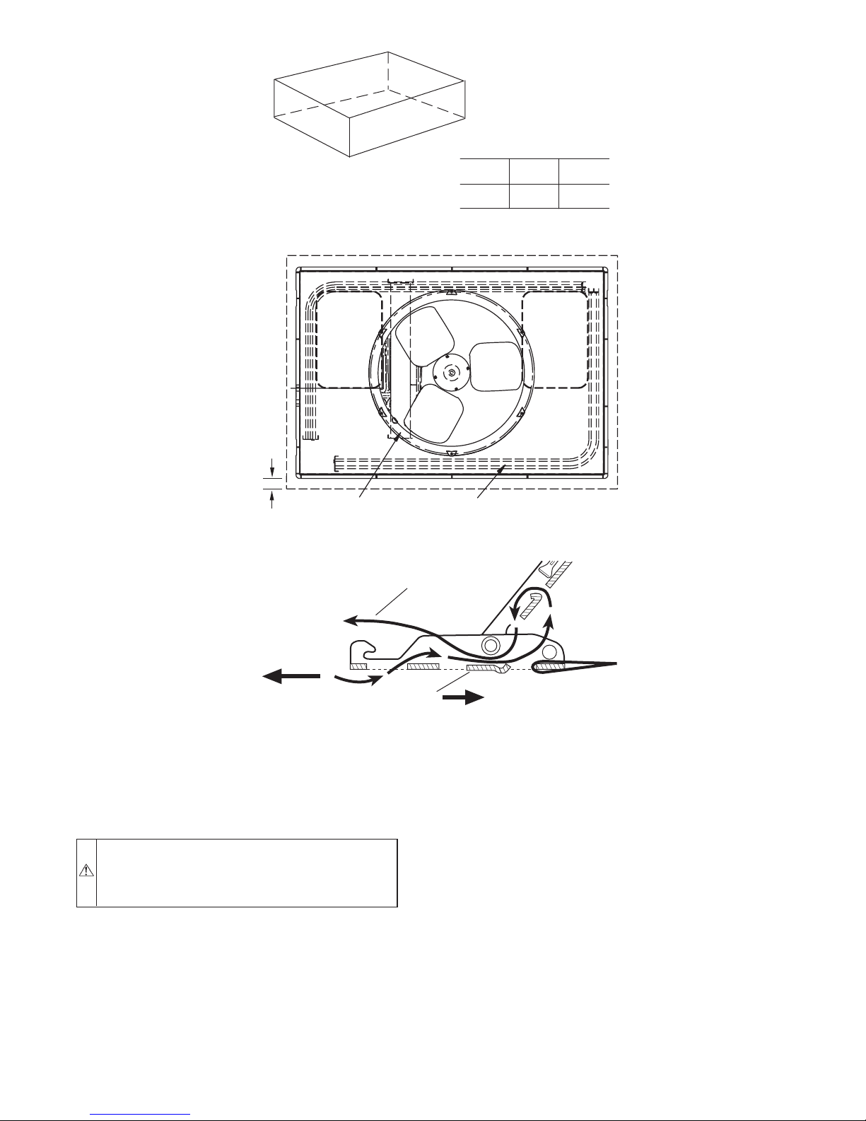
A. CONVERTING HORIZONTAL DISCHARGE UNITS TO
DOWNFLOW (VERTICAL) DISCHARGE UNITS
WARNING: Before performing service or maintenance
operations on system, turn off main power to unit. Turn
off accessory heater power switch if applicable. Electrical
shock could cause serious injury or death.
1. Open all electrical disconnects before starting any service
work.
2. Remove horizontal duct covers to access bottom return and
supply knock out panels.
3. Use a screwdriver and hammer to remove the panels in the
bottom of the unit base.
NOTE: These panels are held in place with tabs similar to an
electrical knockout.
OPTIONAL
SUPPLY
AIR
OPENING
C99096
HANDHOLD
FEED
C99067
4. Reinstall the horizontal duct covers (Fig. 11) to block off
the horizontal air openings.
NOTE: Avoid abrupt duct size increases and reductions. Abrupt
change in duct size adversely affects air performance.
VI. PROVIDE FOR CONDENSATE DISPOSAL
NOTE: Ensure that condensate-water disposal methods comply
with local codes, restrictions, and practices.
The 604B units dispose of condensate through a 3/4 in. NPT
female fitting that exits on the compressor end of the unit.
Condensate water can be drained directly onto the roof in rooftop
installations (where permitted) or onto a gravel apron in ground
level installations. Install a field-supplied condensate trap at end of
condensate connection to ensure proper drainage. Make sure that
the outlet of the trap is at least 1 in. lower than the drain-pan
condensate connection to prevent the pan from overflowing. Prime
the trap with water. When using a gravel apron, make sure it slopes
away from the unit.
If the installation requires draining the condensate water away
from the unit, install a field-supplied 2 -in. trap at the condensate
connection to ensure proper drainage. Condensate trap is available
as an accessory or is field-supplied. Make sure that the outlet of the
—7—
914-137"
“A”
“B”
INSTALL SAFETY STRAPS TO
RIGGING CLEVIS AT 4 RIGGING BRACKETS
PLACE RIGGING BRACKET ASSEMBLY IN 4
RIGGING HOLES AND INSTALL TIE DOWN STRAP
AROUND PERIMETER OF UNIT AND THROUGH
SEE DETAIL A
UNIT MAXIMUM SHIPPING WEIGHT A B
Size lb kg in. mm. in. mm.
604B024 372 169 19.0 482.6 18.25 463.6
604B030 372 169 19.0 482.6 18.25 463.6
604B036 395 179 20.0 508 19.0 482.6
604B042 462 210 20 508 21.25 539.8
604B048 485 220 20.0 508 21.25 539.8
604B060 521 236 21.0 533.4 20.0 508.0
SPACE IN BRACKET ASSEMBLY
(36"-54")
SCALE 0.250
TIGHTEN STRAPPING SECURELY
WITH TENSION BUCKLE
DETAIL A
Fig. 9—Suggested Rigging
C99075
trap is at least 1 in. lower than the unit drain-pan condensate
connection to prevent the pan from overflowing. Connect a drain
trough using a minimum of field-supplied 3/4-in. PVC or fieldsupplied 3/4-in. copper pipe at outlet end of the 2-in. trap. (See Fig.
12) Do not undersize the tube. Pitch the drain trough downward at
a slope of at least 1 in. every 10 ft. of horizontal run. Be sure to
check the drain trough for leaks. Prime the trap at the beginning of
the cooling season start-up.
VII. INSTALL ELECTRICAL CONNECTIONS
WARNING: The unit cabinet must have an uninter-
rupted, unbroken electrical ground to minimize the possibility of personal injury if an electrical fault should
occur. This ground may consist of an electrical wire
connected to the unit ground lug in the control compartment, or conduit approved for electrical ground when
installed in accordance with NEC, ANSI/NFPA American National Standards Institute/National Fire Protection
Association (latest edition) (in Canada, Canadian Electrical Code CSA C22.1) and local electrical codes. Failure
to adhere to this warning could result in serious injury or
death.
CAUTION: Failure to follow these precautions could
result in damage to the unit being installed:
1. Make all electrical connections in accordance with
NEC ANSI/NFPA (latest edition) and local electrical
codes governing such wiring. In Canada, all electrical
connections must be in accordance with CSA standard
C22.1 Canadian Electrical Code Part 1 and applicable
local codes. Refer to unit wiring diagram.
2. Use only copper conductor for connections between
field-supplied electrical disconnect switch and unit.
DO NOT USE ALUMINUM WIRE.
3. Be sure that high-voltage power to unit is within
operating voltage range indicated on unit rating plate.
On 3-phase units, ensure phases are balanced within 2
percent. Consult local power company for correction
of improper voltage and/or phase imbalance.
4. Insulate low-voltage wires for highest voltage contained within conduit when low-voltage control wires
are in same conduit as high-voltage wires.
5. Do not damage internal components when drilling
through any panel to mount electrical hardware, conduit, etc.
—8—
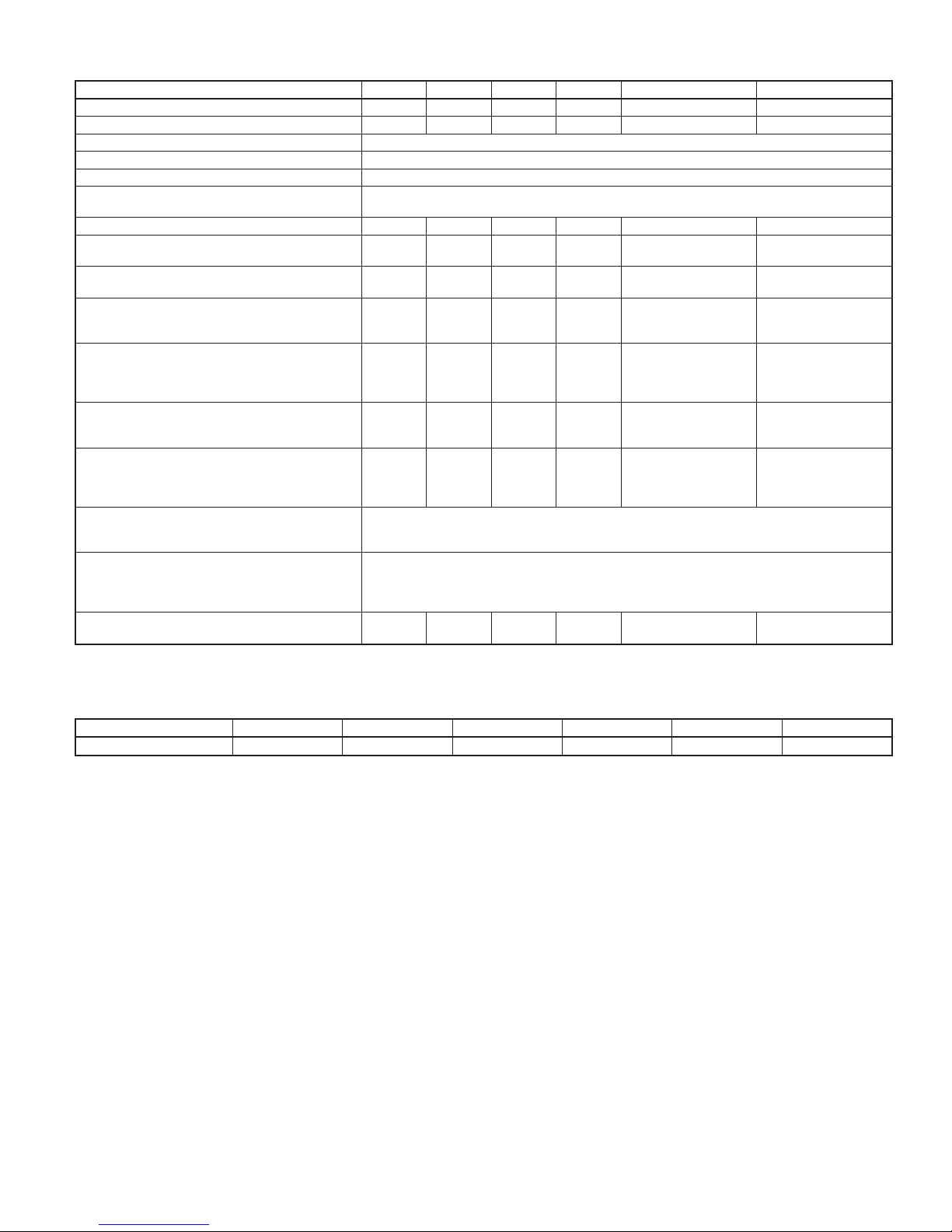
TABLE 1—PHYSICAL DATA—UNIT 604B
UNIT SIZE 604B024 604B030 604B036 604B042 604B048 604B060
NOMINAL CAPACITY (ton) 2 2.5 3 3.5 4 5
OPERATING WEIGHT (lb.) 350 350 373 440 463 499
COMPRESSOR QUANTITY 1
TYPE SCROLL COMPRESSOR
REFRIGERANT R-410A
REFRIGERANT METERING DEVICE
Refrigerant (R-410A) Quantity (lb.) 7.5 8.0 9.5 10.8 11.5 14.0
METERING DEVICE
Nominal Airflow (CFM)
INDOOR BLOWER
Nominal Airflow (CFM)
HIGH-PRESSURE SWITCH (psig)
LOSS-OF-CHARGE/LOW-PRESSURE SWITCH
* Required filter sizes shown are based on the larger of the ARI (Air Conditioning and Refrigeration Institute) rated cooling airflow or the heating airflow velocity of 300
ft/minute for throwaway type or 450 ft/minute for high-capacity type. Air filter pressure drop for non-standard filters must not exceed 0.08 in. wg.
(Liquid Line) (psig)
RETURN-AIR FILTERS (in.)*
ID
ORIFICE OD (in.) 0.035 (2) 0.035 (2) 0.038 (2) 0.038 (2)
OUTDOOR COIL
Rows... Fins/in.
face area (sq. ft.)
OUTDOOR FAN
Diameter
Motor HP (RPM)
INDOOR COIL
Rows... Fins/in.
face area (sq. ft.)
Size (in.)
Motor (HP)
Cutout
Reset (Auto)
Cutout
Reset (Auto)
throwaway
TXV TXV TXV TXV TXV TXV
2...21
12.3
2350
22
1/8 (825)
3...15
3.7
800
10x10
1/2
20x20x1 “ 20x24x1 “ 24x30x1 24x30x1
2...21
12.3
2350
22
1/8 (825)
3...15
3.7
1000
10x10
1/2
2...21
13.6
2800
22
1/8 (825)
4...15
3.7
1100
11x10
3/4
Indoor-TXV
Outdoor-Accurater
0.038 (Left OD Coil)
0.046 (Right OD Coil)
2...21
15.4
2800
22
1/8 (825)
3...15
4.7
1400
11x10
3/4
610±15
420±25
20±5
45±10
2...21
17.2
3300
22
1/4 (1100)
4...15
4.7
1450
11x10
3/4
0.042 (Left OD Coil)
0.052 (Right OD Coil)
2...21
19.4
3300
22
1/4 (1100)
4...15
5.7
1750
11x10
1.0
TABLE 2—MINIMUM AIRFLOW FOR RELIABLE ELECTRIC HEATER OPERATION (CFM)
SIZE 604B024 604B030 604B036 604B042 604B048 604B060
AIRFLOW (CFM) 750 1025 1250 1285 1710 1800
A. HIGH-VOLTAGE CONNECTIONS
The unit must have a separate electrical service with a fieldsupplied, waterproof disconnect switch mounted at, or within sight
from the unit. Refer to the unit rating plate, NEC and local codes
for maximum fuse/circuit breaker size and minimum circuit amps
(ampacity) for wire sizing (See Table 3 for electrical data).
The field-supplied disconnect may be mounted on the unit over the
high-voltage inlet hole (See Figs. 2 and 3).
If the unit has an electric heater, a second disconnect may be
required. Consult the Installation, Start-Up, and Service Instructions provided with the accessory for electrical service connections.
Operation of unit on improper line voltage constitutes abuse and
may cause unit damage that could affect warranty.
B. ROUTING POWER LEADS INTO UNIT
Use only copper wire between disconnect and unit. The highvoltage leads should be in a conduit until they enter the duct panel;
conduit termination at the duct panel must be watertight. Run the
high-voltage leads through the power entry knockout on the power
entry side panel. (See Fig. 2 and 3 for location and size) When the
leads are inside the unit, run leads up the high-voltage raceway to
the line wiring splice box (See Fig. 13 through 17). For singlephase units, connect leads to the black and yellow wires; for
3-phase units, connect the leads to the black, yellow, and blue
wires.
C. CONNECTING GROUND LEAD TO GROUND LUG
Refer to Fig. 16 and 17. Connect the ground lead to the chassis
using the ground lug in the wiring splice box.
D. ROUTING CONTROL POWER WIRES (24-V)
Form a drip-loop with the thermostat leads before routing them
into the unit. Route the thermostat leads through grommeted,
low-voltage hole provided in unit into unit control power splice
box. (See Fig. 2 and 3) Connect thermostat leads to unit control
power leads as shown in Fig. 16.
The unit transformer supplies 24-v power for complete system
including accessory electrical heater. An automatic-reset circuit
breaker (See Fig. 18) is provided in the 24-v circuit; see the caution
label on the transformer or Fig. 19. Transformer is factory wired
for 230-v operation. If supply voltage is 208-v, rewire transformer
primary as described in Special Procedures for 208-v Operation
section.
—9—
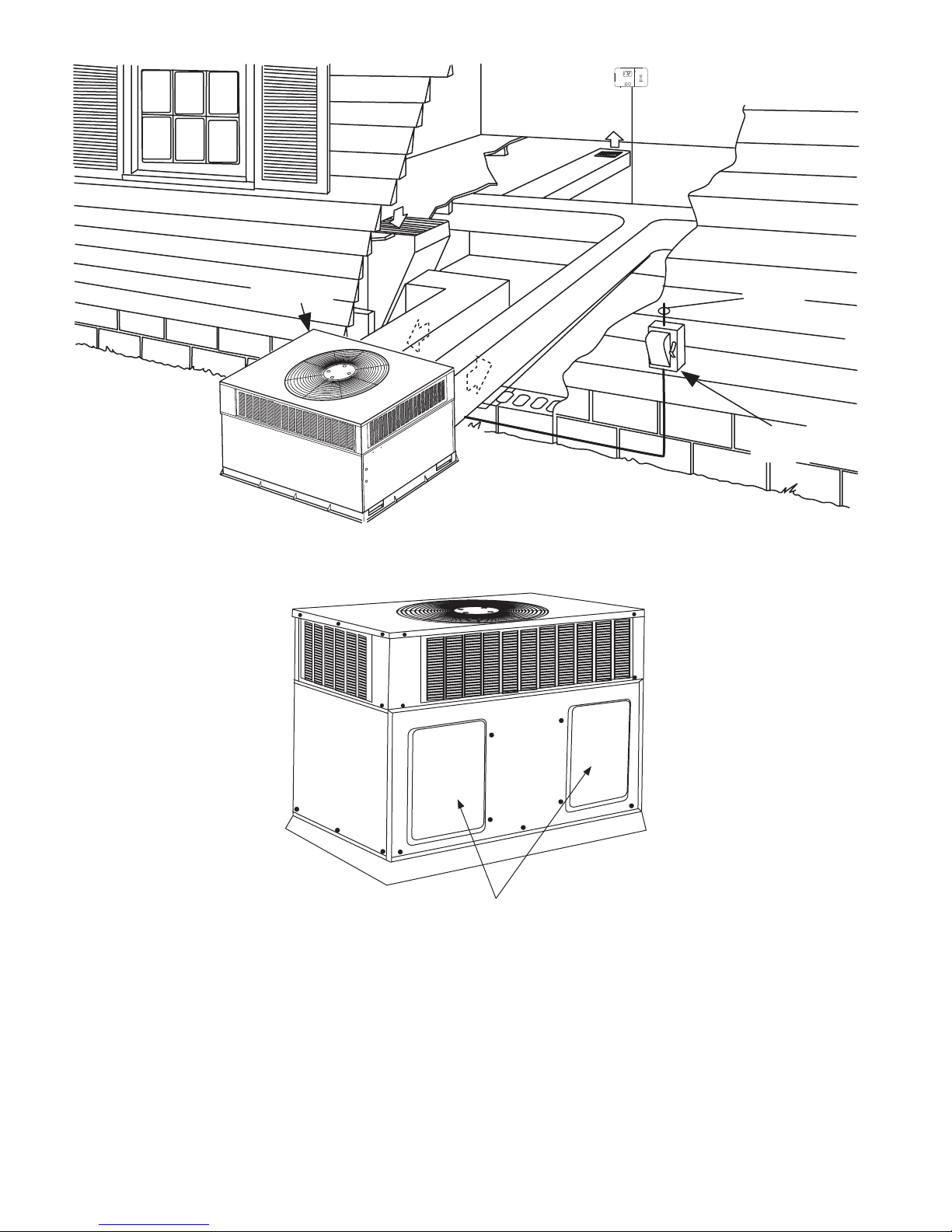
RETURN
AIR
INDOOR
THERMOSTAT
TOP COVER
FROM
POWER
SOURCE
DISCONNECT
PER NEC*
*NEC - NATIONAL ELECTRICAL CODE
C00063
Fig. 10—Typical Installation
E. Easy Select™—604B
EASY SELECT™ CONFIGURATION TAPS FOR 604B
Easy Select™ taps are used by the installer to configure a system.
The ECM motor uses the selected taps to modify its operation to
a pre-programmed table of airflows.
The unit must be configured to operate properly with system
components with which it is installed. To successfully configure a
basic system (see information printed on circuit board label located
next to select pins), move the 6 select wires to the pins which
match the components used.
a. AUX HEAT kW/CFM—SELECT HEATER RANGE
FOR SIZE OF ELECTRIC HEATER INSTALLED
Duct Covers
Fig. 11—604B with Duct Covers On
Installer must select the auxiliary heat airflow approved
for application with kW size heater installed. If no heater
is installed, this step can be skipped. Each select pin is
marked with a range of heaters for which airflow (also
marked), is approved. For increased comfort, select the
narrowest kW range matching the heater size, for example, 0–10 for 10–kW heater. This airflow must be
greater than the minimum for CFM for electric heater
application with the size system installed for safe and
continuous operation. (See Tables 4A, 4B, 4C,5&6for
airflow delivery and minimum CFM.) Note that airflow
marked is the airflow which will be supplied in emer-
—10—
C00092
 Loading...