

Page 1
installation, start-up and
service instructions
SINGLE PACKAGE ROOFTOP
ELECTRIC HEATING/ELECTRICCOOLING UNITS
Cancels: II 558D-36-4 II 558D-36-5
558D
Sizes 036-072
3to6Tons
2/1/99
IMPORTANT — READ BEFORE INSTALLING
1. Read and become familiar with these installation instructions before installing this unit (see Fig. 1).
2. Be sure the installation conforms to all applicable local
and national codes.
3. These instructionscontainimportantinformation for the
proper maintenance and repair of this equipment. Retain these instructions for future use.
CONTENTS
Page
SAFETY CONSIDERATIONS ................... 1
INSTALLATION ...........................1-16
I. Locate the Unit ....................... 3
II. Unit Duct Connections .................. 3
III. Rig and Place Unit ..................... 3
IV. Field Connections ..................... 6
PRE-START-UP ............................17
START-UP ..............................17-28
I. Heating Section Start-Up and Adjustments ....17
II. Cooling Section Start-Up and Adjustments ....18
III. Indoor Airflow and Airflow Adjustments ......19
CARE AND MAINTENANCE ...................28
I. Air Filter ............................28
SERVICE ...............................28-31
I. Cleaning ............................28
II. Lubrication ..........................29
III. Condenser Fan Adjustment ...............29
IV. Refrigerant Charge .....................30
V. Replacement Parts .....................30
TROUBLESHOOTING ......................32-35
START-UP CHECKLIST .....................CL-1
WARNING:
nance operations on unit, turn off main power switch
to unit. Electrical shock could cause personal injury.
1. The power supply (volts, phase, and hertz) must correspond to that specified on unit rating plate.
2. The electrical supply provided by the utility must be sufficient to handle load imposed by this unit.
3. Refer to Locate the Unit section on page 3 and Fig. 2 for
locations of electrical inlets, condensate drain, duct connections and required clearances before setting unit in
place.
4. This installation must conform with local building codes
and with NEC (National Electrical Code) or NFPA
(National Fire Protection Association) 54 TIA-54-84-1.
Refer to Provincial and local plumbing or wastewater
codes and other applicable local codes.
5. Approved for outdoor installation on wood flooring or on
class A, B, or C roof covering materials.
Unit is shipped in the vertical airflow configuration (see
Fig. 1). To convert tohorizontal discharge, remove horizontal
duct opening covers. Using the same screws, install covers
with insulation-side down (facing outside) over vertical duct
openings on the unit. Seals around duct openings must be
tight.
All units can be connected into existing duct systems that are
properly sized and designed to handle an airflow of 300 to
500 cfm per each 12,000 Btuh of rated cooling capacity.
NOTE: When installing any accessory item, see the manufacturer’s installation instructions packaged with the accessory. A qualified installer or agency must use only factoryauthorized kits or accessories when modifying this unit.
Before performing service or mainte-
INSTALLATION
SAFETY CONSIDERATIONS
Recognize safety information. This is the safety-alert symbol ( ). When you see this symbol on the unit and in instructions or manuals, be alert to the potential for personal
injury.
Understand the signal words — DANGER, WARNING, and
CAUTION. These words are used with the safety-alert symbol. Danger identifies the most serious hazards which will
result in severe personal injury or death. Warning indicates
a condition that could result in personal injury. Caution is
used to identify unsafe practices which would result in minor
personal injury or product and property damage.
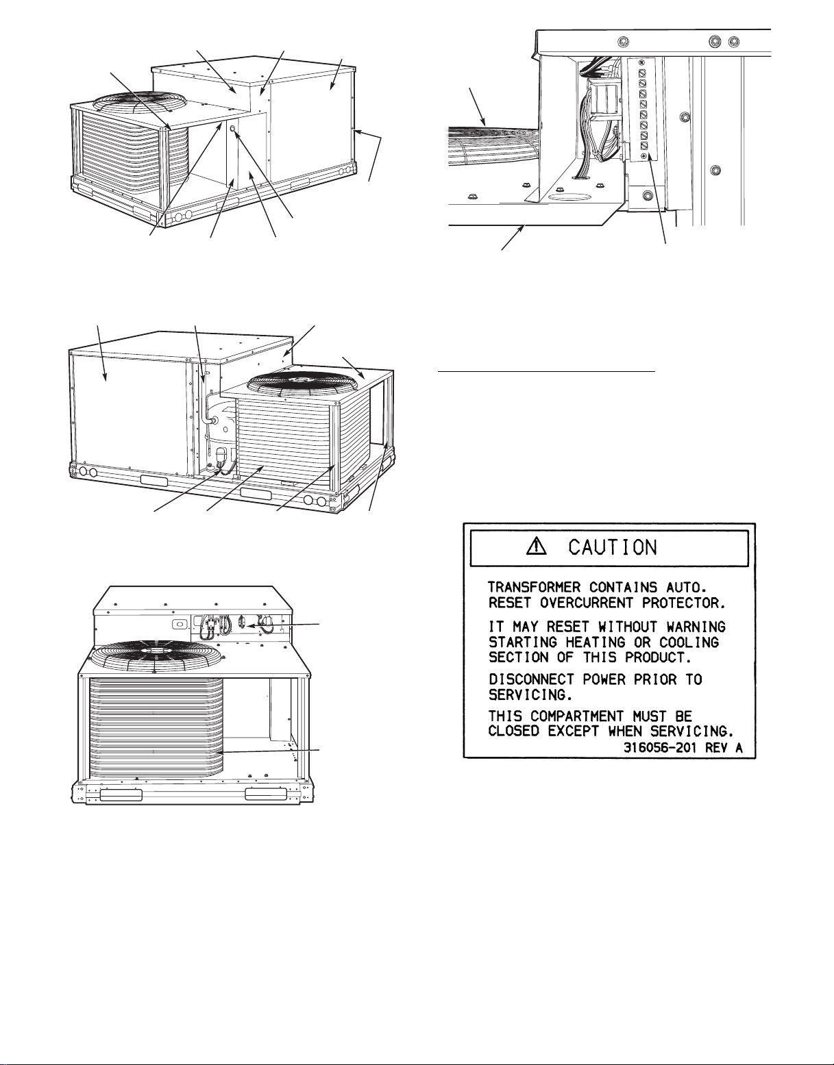
Fig.1—Typical Unit
Page 2
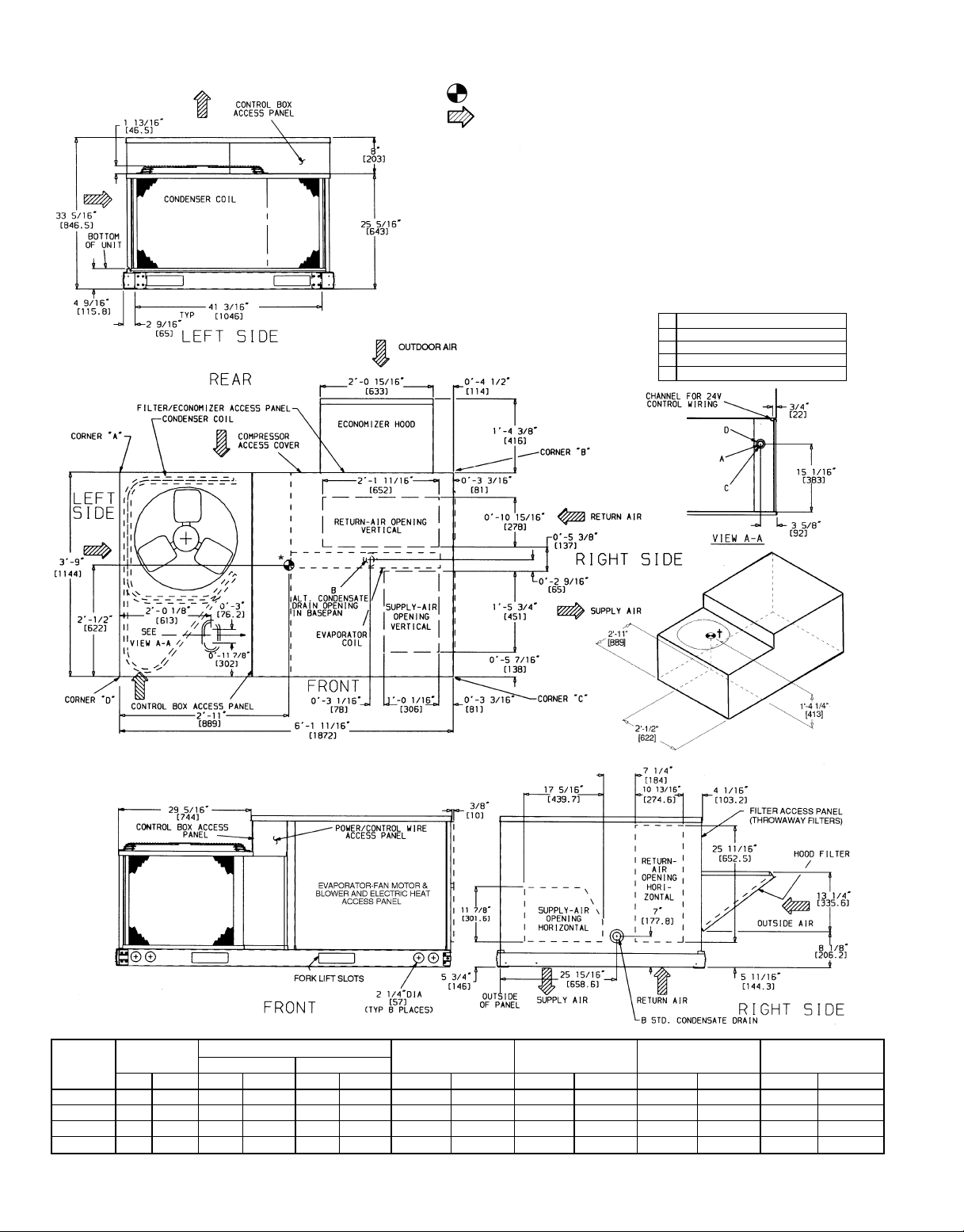
*Indicates horizontal center of gravity.
†Indicates vertical center of gravity.
NOTES:
1. Dimensions in [ ] are in millimeters.
2. Center of gravity.
3. Direction of airflow.
4. Ductwork to be attached to accessory roof curb only.
5. Minimum clearance (local codes or jurisdiction may prevail):
a. Bottom of basepan to combustible surfaces (when not using curb), 0 inches. On
horizontal discharge units with electric heat, 1 in. clearance to ductwork for 1 foot.
b. Condenser coil, for proper airflow, 36 in. one side, 12 in. the other. The side getting
the greater clearance is optional.
c. Overhead, 60 in. to assure proper condenser fan operation.
d. Between units, control box side, 42 in. per National Electrical Code (NEC).
e. Between unit and ungrounded surfaces, control box side, 36 in. per NEC.
f. Between unit and block or concrete walls and other grounded surfaces, control box
side, 42 in. per NEC.
g. Horizontal supply and return end, 0 inches.
6. With the exception of the clearances as stated in Notes 5a, b, and c, a removable
fence or barricade requires no clearance.
7. Units may be installed on combustible floors made from wood or class A, B, or C roof
covering material.
CONNECTION SIZES
1
A 1
⁄89 dia [28.6] field power supply hole
3
B
⁄49-14 NPT condensate drain
3
C 1
⁄89 dia [35] power supply knockout
D 29 dia [50.8] power supply knockout
UNIT
STD UNIT
WEIGHT
ECONOMIZER WEIGHT
DURABLADE PARABLADE
CORNER WEIGHT
(A)
CORNER WEIGHT
(B)
CORNER WEIGHT
(C)
CORNER WEIGHT
(D)
Lb Kg Lb Kg Lb Kg Lb Kg Lb Kg Lb Kg Lb Kg
558D036 365 165.6 34 15.4 42 19.1 126 57.2 89 40.4 111 50.3 39 17.7
558D048 375 170.1 34 15.4 42 19.1 128 58.1 90 40.8 114 51.7 43 19.5
558D060 395 179.2 34 15.4 42 19.1 132 59.9 94 42.6 120 54.4 49 22.2
558D072 470 213.2 34 15.4 42 19.1 148 67.1 103 46.7 155 70.3 64 29.0
Fig. 2 — Base Unit Dimensions
—2—
Page 3
I. LOCATE THE UNIT
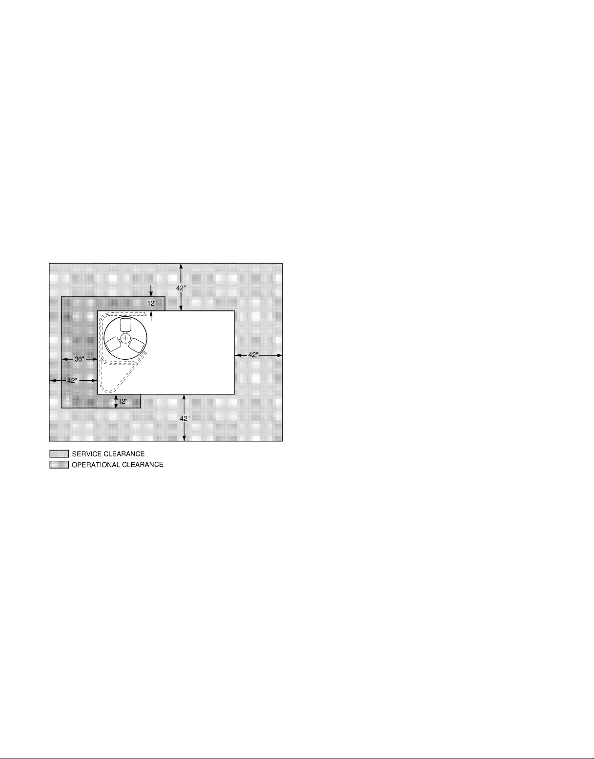
A. Clearance
Maintain clearance around and above unit to provide minimum distance from combustible materials, proper airflow,and
service access (see Fig. 2 and 3).
Minimum clearance to combustibles is 0 in. on all sides.
Minimum clearance to block walls or any other grounded sur-
face is 42 in. on all sides.
Minimum clearance of 36 in. should be providedon side with
outdoor-air intake, if unit is so equipped.
Minimum clearance between unit and other electrically live
parts is 48 inches.
Do not install unit in an indoor location. Do not locate unit
air inlets near exhaust vents or other sources of contaminated air.
Although unit is weatherproof, guard against water from higher
level runoff and overhangs.
Slab mounted units should be at least 4 in. above the highest
expected water, flood and runoff levels. Do not use theunit if
it has been under water.
IMPORTANT: The gasketing of the unit to the roof curb is
critical for a watertight seal. Install gasket with the roof curb
as shown in Fig. 4. Improperly applied gasket can also result
in air leaks and poor unit performance.
Curb should be level. Unit leveling tolerances are shown in
Fig. 5. Correct leveling tolerance is necessary for unit drain
to function properly.
C. Slab Mount (Horizontal Units Only)
Provide a level concrete slab that extends a minimum of
6 in. beyond unit cabinet. Install a gravel apron in front of
condenser-coil air inlet to prevent grass and foliage from
obstructing airflow.
NOTE: Horizontal units may be installed on a roof curb, if
required.
II. UNIT DUCT CONNECTIONS
On vertical units, secure all ducts to roof curb and building
structure. Do not connect ductwork to unit. On horizontal units,
duct flanges should be attached to horizontal openings and
all ductwork should be secured to flanges.
If a plenum return is used on a vertical unit, the return should
be ducted through the roof deck to comply with applicable
fire codes.
Aminimum clearance is not required around ductwork. Cabinet return-air static shall not exceed −0.20 in. wgwith PARABLADE economizer, −0.35 in. wg with Durablade economizer,
or −0.45 in. wg without economizer.
NOTE: Connection must be made to roof curb before unit is
set in place.
Fig. 3 — Service and Operational Clearances
B. Roof Curb Mount
Assemble and install accessory roof curb in accordance with
instructions shipped with curb. See Fig. 4. Install insulation,
cant strips, roofing felt, and counter flashing as shown. Duct-
work must be attached to curb. If electric or control power is
to be routed through the curb, attach the accessorythru-thebottom connections to the basepan in accordance with the accessory installation instructions. Accessory electric connections
must be installed before unit is in place on roof curb.
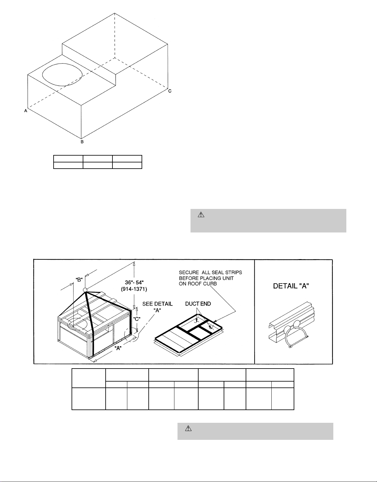
III. RIG AND PLACE UNIT
Inspect unit for transportation damage. File any claim with
transportation agency. Keep unit upright and do not drop.
Spreader bars are not required if top crating is left on unit.
Rollers may be used to move unit across a roof. Level by using unit frame as a reference. See Table 1 and Fig. 6 for additional information. Operating weight and maximum weight
are shown in Table 1 and Fig. 6.
Lifting holes are provided in base rails as shown in Fig. 6.
Refer to rigging instructions on unit.
IMPORTANT: If unit has forklift protection skids, be sure to
remove forklift protection skids from under unit before setting unit in place.
A properly positioned unit will have the following clearances
between unit and roof curb:
and base rails on each side and front of unit; 1
1
⁄4-in. clearance between roof curb
5
⁄32-in. clearance between roof curb and rear of unit. See Fig. 4, Views
A-A and C-C.
After unit is in position, remove shipping materials and rigging skids.
—3—
Page 4
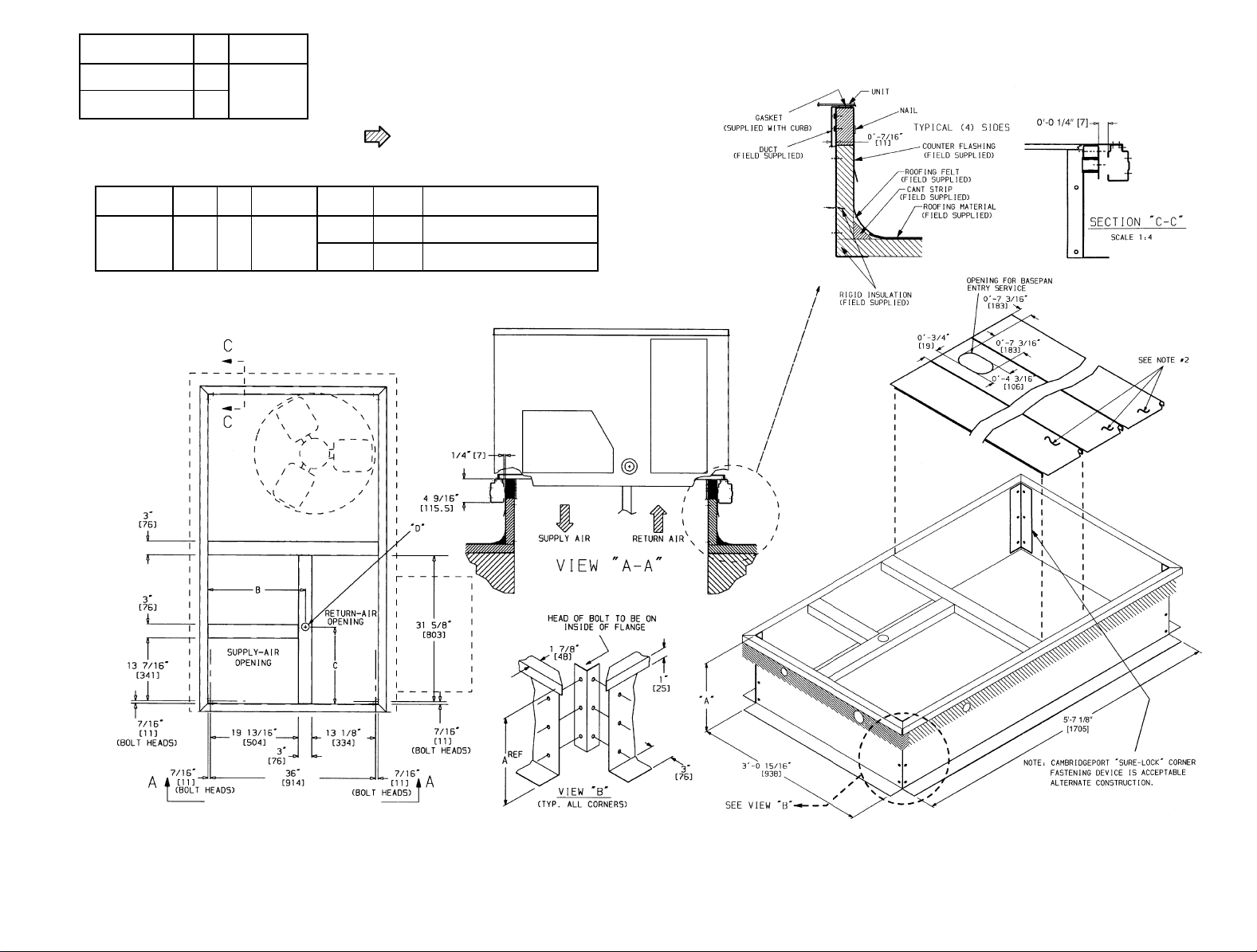
ROOF CURB
ACCESSORY
CRRFCURB001A00
CRRFCURB002A00
‘‘A’’ UNIT SIZE
149
[356]
558D036-072
249
[610]
NOTES:
1. Roof curb accessory is shipped unassembled.
2. Insulated panels.
3. Dimensions in [ ] are in millimeters.
4. Roof curb: galvanized steel.
5. Attach ductwork to curb. (Flanges of duct rest on
curb.)
6. Service clearance 4 ft on each side.
7. Direction of airflow.
—4—
UNIT SIZE ‘‘B’’ ‘‘C’’
11
⁄
16
9
558D036-072
21
[551]
169
[406]
‘‘D’’Alt
Drain Hole
13⁄
4
9
[44.5]
Power Control Connector Package Accessory
3
⁄49 NPT1⁄29 NPT
1
⁄49 NPT1⁄29 NPT
1
CRBTMPWR001A00
(THRU-THE-BOTTOM)
CRBTMPWR002A00
(THRU-THE-BOTTOM)
Fig. 4 — Roof Curb
Page 5
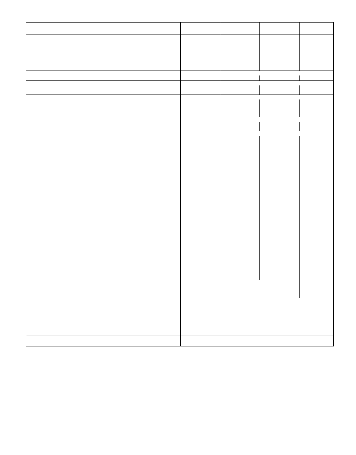
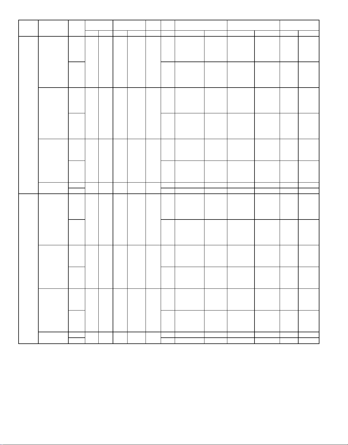
Table 1 — Specifications
BASE UNIT 558D 036 048 060 072
NOMINAL CAPACITY (tons) 3456
OPERATING WEIGHT (lb)
Unit 365 375 395 470
Durablade Economizer 34 34 34 34
PARABLADE Economizer 42 42 42 42
Roof Curb 115 115 115 115
COMPRESSOR TYPE Reciprocating Reciprocating Reciprocating Scroll
Quantity 1111
Oil (oz) 50 50 50 54
REFRIGERANT TYPE R-22
Operating Charge (lb-oz) 3-6 5-8 7-0 7-11
CONDENSER COIL Enhanced Copper Tubes, Aluminum Lanced Fins
Rows...Fins/in. 1...17 1...17 2...17 2...17
Total Face Area (sq ft) 7.36 13.19 10.42 10.42
CONDENSER FAN Propeller Type
Nominal Cfm 3500 4000 4000 4000
Quantity...Diameter (in.) 1...22.0 1...22.0 1...22.0 1...22.0
Motor Hp...Rpm
Watts Input (Total) 325 325 325 325
EVAPORATOR COIL Enhanced Copper Tubes, Aluminum Double-Wavy Fins
Rows...Fins/in. 2...15 2...15 3...15 4...15
Total Face Area (sq ft) 4.17 5.5 5.5 5.5
EVAPORATOR FAN Centrifugal Type
Quantity...Size (in.) Std 1...10 x 10 1...10 x 10 1...11 x 10 1...10 x 10
Type Drive Std Direct Direct Direct Belt
Nominal Cfm Std 1200 1600 2000 2400
Maximum Continuous Bhp Std .34 .75 1.20 2.40
Motor Frame Size Std 48 48 48 56
Nominal Rpm High/Low Std 860/800 1075/970 1075/970 —
Fan Rpm Range Std — — — 1070-1460
Motor Bearing Type Ball Ball Ball Ball
Maximum Allowable Rpm 2100 2100 2100 2100
Motor Pulley Pitch Diameter Min/Max (in.) Std — — — 2.8/3.8
Nominal Motor Shaft Diameter (in.) Std
Fan Pulley Pitch Diameter (in.) Std ———4.5
Belt, Quantity...Type...Length (in.) Std — — — 1...A...40
Pulley Center Line Distance (in.) Std — — — 14.7-15.5
Speed Change per Full Turn of Std ———80
Movable Pulley Flange (rpm) Alt 65 70 80 —
Movable Pulley Maximum Full Turns Std ———5
From Closed Position Alt 555—
Factory Setting Std ———3
Factory Speed Setting (rpm) Std — — — 1225
Fan Shaft Diameter at Pulley (in.)
HIGH-PRESSURE SWITCH (psig)†
Standard Compressor Internal Relief (Differential) 450±50 500±50
Cutout 428 428
Reset (Auto.) 320 320
LOW-PRESSURE/LOSS-OF-CHARGE SWITCH (Liquid Line)(psig)†
Cutout 7±3
Reset (Auto.) 22±7
FREEZE-PROTECTION THERMOSTAT (F)†
Opens 30±5
Closes 45±5
OUTDOOR-AIR INLET SCREENS Cleanable
Quantity...Size (in.) 1...20 x 24 x 1
RETURN-AIR FILTERS Throwaway
Quantity...Size (in.) 2...16 x 25 x 2
Alt 1...10 x 10 1...10 x 10 1...10 x 10 —
Alt Belt Belt Belt —
Alt 1200 1600 2000 —
Alt 1.00 1.00 1.3/2.4* —
Alt 48 48 48/56* —
Alt ————
Alt 760-1090 840-1185 900-1300 —
Alt 1.9/2.9 1.9/2.9 2.4/3.4 —
Alt
Alt 4.5 4.0 4.5 —
Alt 1...A...39 1...A...36 1...A...39 —
Alt 10.0-12.4 10.0-12.4 14.7-15.5 —
Alt 333—
Alt 890 980 1060 —
LEGEND
Bhp — Brake Horsepower
*Single phase units — 1.3 bhp/48 frame.
Three phase units — 2.4 bhp/56 frame.
†Requires an optional or accessory controls upgrade kit.
1
⁄4...1100
1
⁄
1
⁄
5
⁄
1
⁄4...1100
2
2
8
1
⁄
2
1
⁄
2
5
⁄
8
1
⁄4...1100
1
⁄
5
⁄
5
⁄
1
⁄4...1100
2
8
8
5
⁄
8
—
5
⁄
8
—5—
Page 6
MAXIMUM ALLOWABLE DIFFERENCE (in.)
A-B B-C A-C
0.5 1.0 1.0
Fig. 5 — Unit Leveling Tolerances
IV. FIELD CONNECTIONS
A. External Trap Condensate Drain
The unit’s
3
⁄4-in. condensate drain connections are located
on the bottom and side of the unit. Unit discharge connections do not determine the use of drain connections; either
drain connection can be used with vertical or horizontal
applications.
When using the standard side drain connection, make sure
the plug in the alternate bottom connection is tight before installing the unit.
To use the bottom drain connection for a roof curb installation, relocate the factory-installed plug from the bottom connection to the side connection. See Fig. 7. The piping for the
condensate drain and external trap can be completed after
the unit is in place.
All units must have an external trap for condensate drainage. Install a trap at least 4-in. deep and protect against freezeup. See Fig. 8. If drain line is installed downstream from the
external trap, pitch the line away from the unit at 1 in. per
10 ft of run. Do not use a pipe size smaller than the unit
connection.
B. Field Duct Connections
NOTE: The design and installation of the duct system must
be in accordance with NFPA standards for the installation of
nonresidence-type air conditioning and ventilating systems,
NFPANo. 90A or residence-type, NFPANo. 90B, and/or local
codes and ordinances.
Adhere to the following criteria when selecting, sizing and
installing the duct system:
1. Remove appropriate panels from unit to obtain either
horizontal or vertical discharge. If units are installed in
horizontal discharge applications, remove vertical discharge duct covers, save screws and install covers over
vertical duct openings.
2. Select and size ductwork, supply-air registers and returnair grilles according to ASHRAE (American Society of
Heating, Refrigeration and Air-Conditioning Engineers) recommendations.
CAUTION:
When drilling the duct system fastening
holes into the side of the unit for duct flanges, be careful not to puncture the coil or coil tubes. See Fig. 9.
MAX
UNIT
558D036 415 188
558D048 425 193
558D060 445 202
558D072 520 236
NOTES:
1. Dimension in ( ) is in millimeters.
2. Hook rigging shackles through holes in base rail, as shown in
detail ‘‘A.’’ Holes in base rails are centered around the unit
center of gravity. Use wooden top skid when rigging to prevent rigging straps from damaging unit.
3. Weights do not include economizer. See Table 1 for economizer weights.
WEIGHT
Lb Kg in. mm in. mm in. mm
73.69 1872 35.00 889 33.35 847
Fig. 6 — Rigging Details
‘‘A’’ ‘‘B’’ ‘‘C’’
CAUTION: All panels must be in place when
rigging.
—6—
Page 7
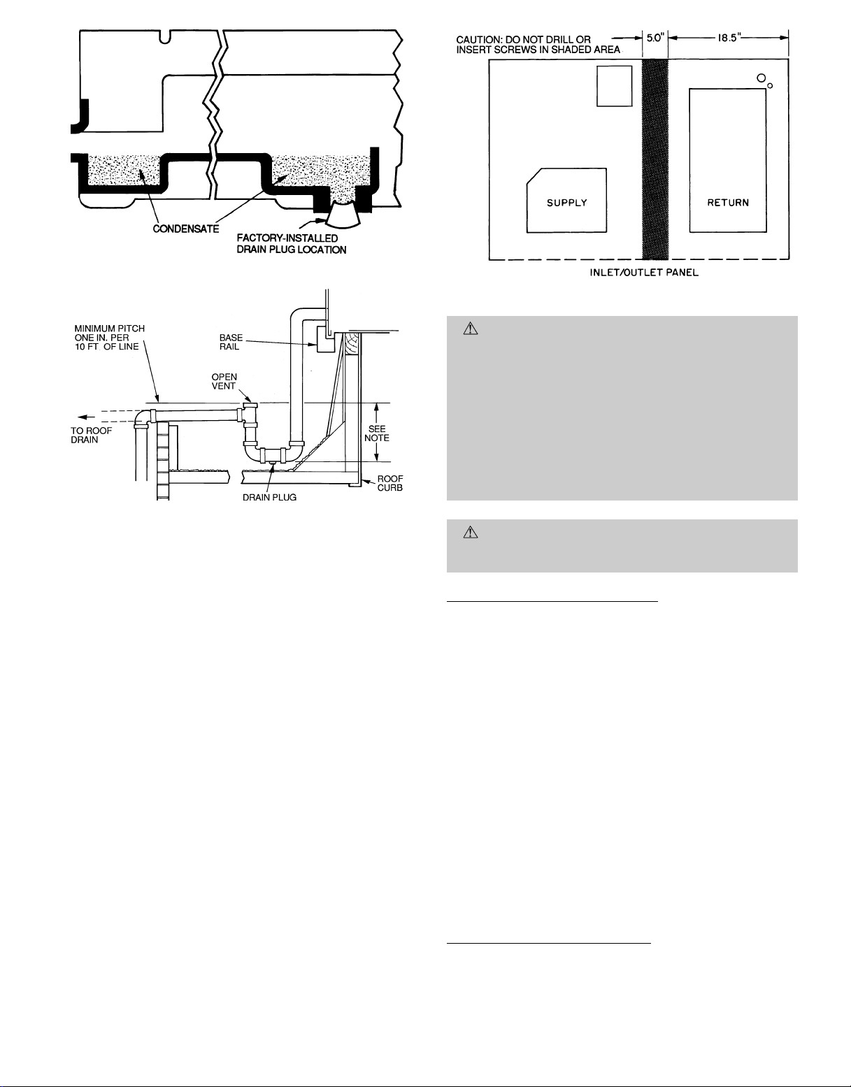
Fig. 7 — Internal Trap Condensate Drain
Fig. 9 — Location of Coil Area Not to be Drilled
C. Electrical Connections
NOTE: Trap should be deep enough to offset maximum unit static dif-
ference. A 4-in. trap is recommended.
Fig. 8 — External Trap Condensate Drain
3. Use flexibletransition between rigid ductwork andunit
to prevent transmission of vibration. The transition may
be screwed or bolted to duct flanges. Use suitable gaskets to ensure weather- and airtight seal.
4. When horizontal return is used, install external field-
supplied air filter(s) in return-air ductwork where it is
easily accessible for service. Recommended filter sizes
are shown in Table 1.
5. Size all ductwork for maximum required airflow(either
heating or cooling) for unit being installed.Avoidabrupt
duct size increases or decreases.
6. Adequately insulate and weatherproof all ductwork
located outdoors. Insulate ducts passing through unconditioned space, and use vapor barrier in accordance
with latest issue of SMACNA (Sheet Metal and Air Conditioning Contractors National Association) and ACCA
(Air Conditioning Contractors NationalAssociation) minimum installation standards for heating and air conditioning systems. Secure all ducts to building structure.
A minimum clearance to combustibles is not required
around ductwork on vertical discharge units. On horizontal discharge units, a minimum clearance of one in.
is required for the first 12 in. of ductwork.
7. Flash, weatherproof and vibration-isolate all openings
in building structure in accordance with local codes and
good building practices.
WARNING:
The unit cabinet must have an uninterrupted, unbroken, electrical ground to minimize the possibility of personal injury if an electrical fault should
occur. This ground may consist of electrical wire connected to the unit ground lug in the control compartment or conduit approved for electrical ground when
installed in accordance with NEC ANSI (American
National Standards Institute)/NFPA, latest edition,
(in Canada, Canadian Electrical Code CSA [Canadian
StandardsAssociation] C22.1); and local electrical codes.
Failure to adhere to this warning could result in personal injury.
CAUTION:
Failure to obey the following precautions could result in damage to the unit being
installed:
Field Power Supply (Fig. 10 and 11)
1. Make allelectrical connections in accordance with NEC
ANSI/NFPA,latest edition, and local electrical codes governing such wiring. In Canada, all electrical connections must be in accordance with CSA Standard C22.1
Canadian Electrical Code Part 1 and applicable local codes.
Refer to unit wiring diagram.
2. A unit disconnect switch is required within sight from
the unit. The disconnectswitch may be mounted on the
unit corner post. When mounting disconnect switch, be
sure the unit rating plate is not obstructed.
3. Use only copper conductor for connections between fieldsupplied electrical disconnect switch and unit. The use
of aluminum wire is not recommended. Maximum wire
size is number 2 AWG (American Wire Gage) on units
without heat. The maximum wire size is number 2/0 A WG
on units with heat.
4. Insulate low-voltage wires for highest voltage contained within conduit when low-voltage control wires are
run in same conduit as high-voltage wires.
5. Do not damage internal components when drilling through
any panel to mount electrical hardware, conduit, etc.
High-Voltage Connections (Fig. 10)
The unit must have a separate electrical service with a field-
supplied, waterproof, fused, disconnect switch mounted at, or
within sight of, the unit. Refer to the unit rating plate for
maximum fuse/circuit breaker size and minimum circuit amps
(ampacity) for wire sizing. Be sure disconnect switch does not
obstruct unit rating plate.
—7—
Page 8
The field-supplied disconnect switch box may be mounted on
the unit’s end panel or on the corner post. Mount disconnect
box on the left side of the rating platewhen mounting on the
unit’s end panel. Do not mount the disconnect box over the
unit rating plate. When mounting disconnect box on corner
post, secure disconnect box to corner post and condenser coil
top cover. See Fig. 12.
A disconnect box mounting space is available when an optional or accessory condenser coil grille is used. Mount the
disconnect on the sheet metal provided with the condenser
coil grille. The sheet metal is located adjacent to the corner
post on the left side of the power wiring access panel.
Install field wiring as follows:
1. Connect ground lead to chassis ground connection when
using separate ground wire.
2. Install conduit between disconnect and power wiring access panel. Insert conduit through power supply knockout opening. See Fig. 12.
3. Install power lines to power wiring leads.
4. Pigtails are provided for field power connections and are
located inside the power wiring access panel. See
Fig. 11. Use factory-supplied splices or Underwriters’ Laboratories (UL) approved copper connector.
Voltage to compressor terminals during operation must
be within voltage range indicated on unit nameplate (see
Table2). On 3-phase units, voltagesbetween phases must be
balanced within 2% and the current within 10%. Usethe formula shown in the legend for Table 2, Note 2 to determine
the percent of voltage imbalance. Operation on improper line
voltage or excessive phase imbalance constitutes abuse and
may cause damage to electrical components. Such operation
would invalidate any applicable warranty.
Special Procedures for 208-V Operation
Control Voltage Connection
Install a factory-approved room thermostat. Locate the ther-
mostat on an inside wall in the space to be conditioned where
it will not be subjected to either a cooling or heating source
or direct exposure to sunlight. Mount the thermostat 4 to 5 ft
above the floor. See accessory installation instructions.
NOTE: For wire runs up to 50 ft, use number 18 AWG insulated wire (35 C minimum). For 51 to 75 ft, use number 16
AWG insulated wire (35 C minimum). For 76 to 150 ft, use
number 14 AWGinsulated wire (35 C minimum). All wire larger
than number 18 AWGcannot be connected directly to the thermostat and will require a junction box and splice at the
thermostat.
Feed control wires through the raceway located between the
condenser coil top cover and power wiring access panel. See
Fig. 12. Connect control wires to the low-voltage connections
located inside low-voltage access panel. See Fig. 10, 11, and
13 for connections. The barrier provides the UL required clearance between high- and low-voltage wiring.
NOTE: If thru-the-bottom power connections are used refer
to the accessory installation instructions for information on
power wiring. Refer to Fig. 2 for drilling holes in basepan.
DANGER: Make sure that the power supply to the
unit is switched OFF before making any wiring changes.
Electrical shock can cause personal injury or death.
For operation on 208 v, disconnect the transformer primary
orange lead from the contactor.See the unit wiring label. Remove the tape and cover from the terminal on the end of the
transformer primary red lead. Save the cover. Connect the
red lead to the contactor terminal from which the orange lead
was disconnected.
Using the cover removed from the red lead, insulate the loose
terminal on the orange lead. Wrap the cover with electrical
tape so that the metal terminal cannot be seen.
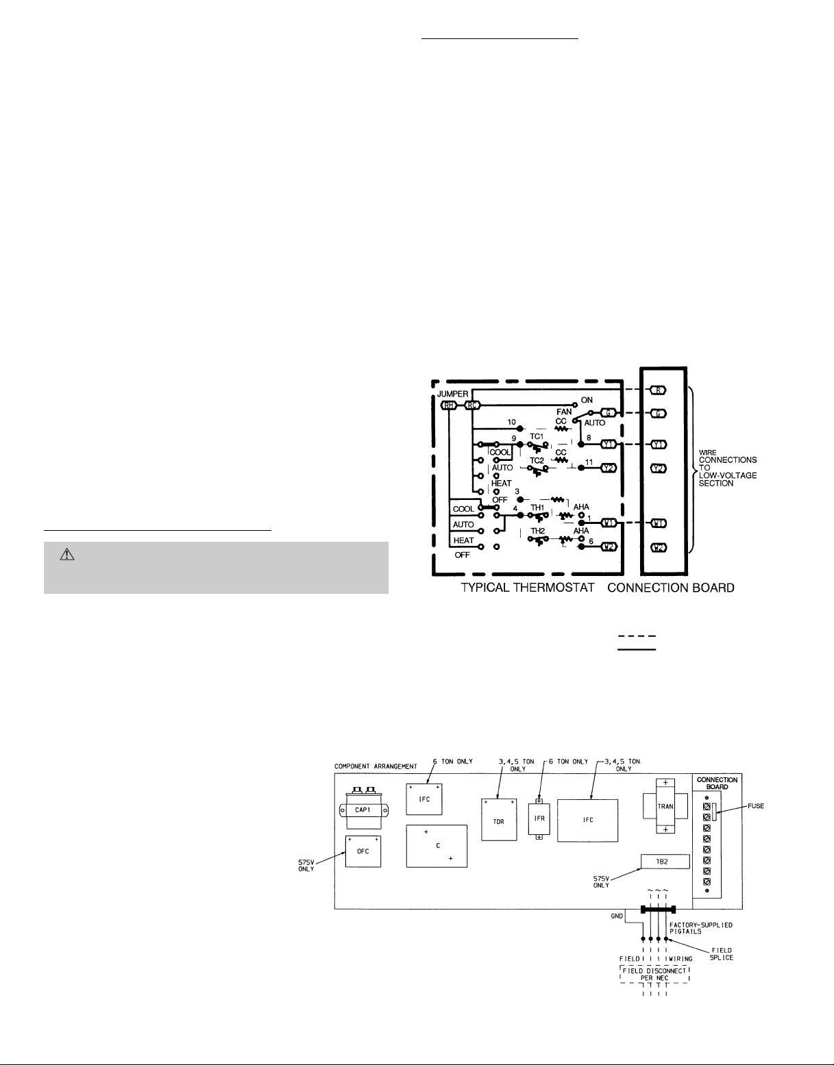
LEGEND
C—Contactor
CAP — Capacitor
GND — Ground
IFC — Indoor (Evaporator) Fan Contactor
IFR — Indoor (Evaporator) Fan Relay
NEC — National Electrical Code
OFC — Outdoor (Condenser) Fan Contactor
TB — Terminal Block
TDR — Time-Delay Relay
TRAN — Transformer
LEGEND
AHA — Adjustable Heat Anticipator
CC — Cooling Compensator
TC — Thermostat-Cooling
NOTES:
1. The Y2 wiring is connected when an economizer is used.
2. Connect W1 when unit is equipped with an accessory 1-module heater
package. The W2 wiring is connected when unit is equipped with an
accessory 2-module heater package.
TH — Thermostat-Heating
Field Wiring
Factory Wiring
Fig. 11 — Low-Voltage Connections
Fig. 10 — Field Wiring Connections
—8—
Page 9
UNIT DISCONNECT
(NOT SHOWN)
FIELD CONTROL
WIRING RACEWAY
(HIDDEN)
CONTROL BOX
ACCESS PANEL
POWER WIRING
SIDE PANEL
LOW-VOLTAGE
ACCESS PANEL
KNOCKOUT
OPENING
POWER WIRING
ACCESS PANEL
EVAPORATOR
FAN ACCESS
PANEL
END PANEL
(HIDDEN)
CONDENSER
FAN
RACEWAY
(HIDDEN)
R
Y1
Y2
W1
W2
G
C
X
LOW-VOLTAGE WIRING
CONNECTION
FILTER
ACCESS PANEL
COMPRESSOR
(COMPRESSOR
ACCESS PANEL
NOT SHOWN)
REFRIGERANT SERVICE
PORT ACCESS P ANEL
(NOT SHOWN)
CONDENSER
COIL
CONTROL BOX
ACCESS PANEL
LEFT
CORNER
POST
CONDENSER COIL
TOP COVER
RIGHT
CORNER
POST
CONTROL BOX
Fig. 13 — Low-Voltage Location
Transformer Circuit Breaker (Fig. 14)
The unit transformer contains an automatic-reset overcur-
rent protector for control circuit protection. If this device trips,
it may reset without warning and start the heating or
cooling section of this product. Use caution when servicing: If
overcurrent protector continues to trip, there is a problem in
the low-voltage electrical circuit (i.e., electrical short, ground
or transformer overload). Disconnect power, correct the condition, and check for normal unit operation.
CONDENSER
COIL
Fig. 12 — Typical Component Location
Fig. 14 — Transformer Label
—9—
Page 10
UNIT
558D
036
(3 Ton)
048
(4 Ton)
NOMINAL
V-PH-Hz
208/230-1-60
208/230-3-60
460-3-60
575-3-60
208/230-1-60
208/230-3-60
460-3-60
575-3-60
Table 2 — Electrical Data
VOLTAGE
IFM
TYPE
Std
Alt 4.9
Std
Alt 4.9
Std
Alt 2.1
Std
Alt 2.1\ — — 7.4 15 7 34
Std
Alt 4.9
Std
Alt 4.9
Std
Alt 2.1
Std
Alt 2.1\ — — 10.9 15 11 43
RANGE
Min Max RLA LRA FLA FLA Nominal kW FLA MCA MOCP† FLA LRA
187 254 16.9 86.7 1.4
187 254 11.7 65.1 1.4
414 508 5.1 32.8 0.8
518 632 4.1 27.0 0.8\
187 254 23.3 118.0 1.4
187 254 15.4 90.0 1.4
414 508 8.3 45.0 0.8
518 632 6.4 36.0 0.8\
COMPR
(each)
OFM IFM ELECTRIC HEAT* POWER SUPPLY
— — 25.3/ 25.3 35/ 35 24/ 24 97/ 97
3.3/ 4.4 15.9/18.3 25.3/ 26.4 35/ 35 24/ 24 97/ 97
2.8
2.8
1.3
1.3\ — — 6.8 15 7 31
3.5
3.5
1.8
1.8\ — — 10.6 15 10 42
4.9/ 6.5 23.8/27.3 32.8/ 37.4 35/ 40 30/ 34 97/ 97
6.5/ 8.7 31.4/36.2 42.8/ 48.8 45/ 50 39/ 45 97/ 97
7.9/10.5 37.9/43.8 50.9/ 58.2 60/ 60 47/ 54 97/ 97
9.8/13.0 47.1/54.6 62.2/ 71.2 70/ 80†† 57/ 66 97/ 97
— — 27.4/ 27.4 35/ 35 27/ 27 102/102
3.3/ 4.4 15.9/18.3 27.4/ 29.0 35/ 35 27/ 27 102/102
4.9/ 6.5 23.5/27.1 35.5/ 40.0 35/ 40 33/ 37 102/102
6.5/ 8.7 31.4/36.3 45.4/ 51.4 45/ 60 42/ 47 102/102
7.9/10.5 37.9/43.8 53.5/ 60.8 60/ 60 49/ 56 102/102
9.8/13.0 46.9/54.2 64.8/ 73.8 70/ 80†† 60/ 68 102/102
— — 18.8/ 18.8 25/ 25 18/ 18 76/ 76
3.3/ 4.4 9.2/10.6 18.8/ 18.8 25/ 25 18/ 18 76/ 76
4.9/ 6.5 13.6/15.6 20.4/ 23.0 25/ 25 19/ 21 76/ 76
6.5/ 8.7 18.1/20.9 26.2/ 29.7 30/ 30 24/ 27 76/ 76
7.9/10.5 21.9/25.3 30.9/ 35.1 35/ 40 28/ 32 76/ 76
12.0/16.0 33.5/38.6 45.3/ 51.7 50/ 60 42/ 48 76/ 76
— — 20.9/ 20.9 25/ 25 21/ 21 80/ 80
3.3/ 4.4 9.2/10.6 20.9/ 20.9 25/ 25 21/ 21 80/ 80
4.9/ 6.5 13.6/15.6 23.1/ 25.7 25/ 25 21/ 24 80/ 80
6.5/ 8.7 18.1/20.9 28.8/ 32.3 30/ 35 26/ 30 80/ 80
7.9/10.5 21.9/25.3 33.5/ 37.7 35/ 40 31/ 35 80/ 80
12.1/16.0 33.5/38.6 47.9/ 54.4 50/ 60 44/ 50 80/ 80
— — 8.5 15 8 38
6.0 7.2 10.6 15 10 38
8.8 10.6 14.9 15 14 38
11.5 13.8 18.9 20 17 38
14.0 16.8 22.7 25 21 38
— — 9.3 15 9 41
6.0 7.2 11.6 15 10 41
8.8 10.6 15.9 20 15 41
11.5 13.8 19.9 20 18 41
14.0 16.8 23.7 25 22 41
— — 34.0/ 34.0 40/ 40 32/ 32 128/128
3.3/ 4.4 15.9/18.3 34.0/ 34.0 40/ 40 32/ 32 128/128
6.5/ 8.7 31.4/36.3 43.6/ 49.7 45/ 50 40/ 46 128/128
9.8/13.0 46.9/54.2 63.0/ 72.1 70/ 80†† 58/ 66 128/128
13.1/17.4 62.8/72.5 82.9/ 95.0 90/100†† 76/ 87 128/128
15.8/21.0 75.8/87.5 99.2/113.8 100/125†† 91/105 128/128
— — 35.4/ 35.4 40/ 40 34/ 34 129/129
3.3/ 4.4 15.9/18.3 35.4/ 35.4 40/ 40 34/ 34 129/129
6.5/ 8.7 31.4/36.3 45.4/ 51.4 45/ 60 42/ 47 129/129
9.8/13.0 46.9/54.2 64.8/ 73.8 70/ 80†† 60/ 68 129/129
13.1/17.4 62.8/72.5 84.7/ 96.8 90/100†† 78/ 89 129/129
15.8/21.0 75.8/87.5 100.9/115.5 100/125†† 93/106 129/129
— — 24.2/ 24.2 30/ 30 24/ 24 100/100
4.9/ 6.5 13.6/15.6 24.2/ 24.2 30/ 30 24/ 25 100/100
6.5/ 8.7 18.1/20.9 27.0/ 30.5 30/ 35 27/ 30 100/100
12.0/16.0 33.4/38.5 46.1/ 52.5 50/ 60 45/ 51 100/100
15.8/21.0 43.8/50.5 59.1/ 67.5 60/ 70†† 58/ 64 100/100
— — 25.6/ 25.6 30/ 30 24/ 24 101/101
4.9/ 6.5 13.6/15.6 25.6/ 25.7 30/ 30 24/ 24 101/101
6.5/ 8.7 18.1/20.9 28.8/ 32.3 30/ 35 25/ 29 101/101
12.0/16.0 33.4/38.5 47.8/ 54.2 50/ 60 43/ 49 101/101
15.8/21.0 43.8/50.5 60.8/ 69.3 60/ 70†† 55/ 63 101/101
— — 13.0 15 13 51
6.0 7.2 13.0 15 13 51
11.5 13.8 19.5 20 18 51
14.0 16.6 23.0 25 21 51
23.0 27.7 36.8 40 34 51
— — 13.3 15 13 52
6.0 7.2 13.3 15 13 52
11.5 14.0 19.9 20 18 52
14.0 16.6 23.4 25 22 52
23.0 27.7 37.2 40 34 52
DISCONNECT
SIZE**
—10—
Page 11
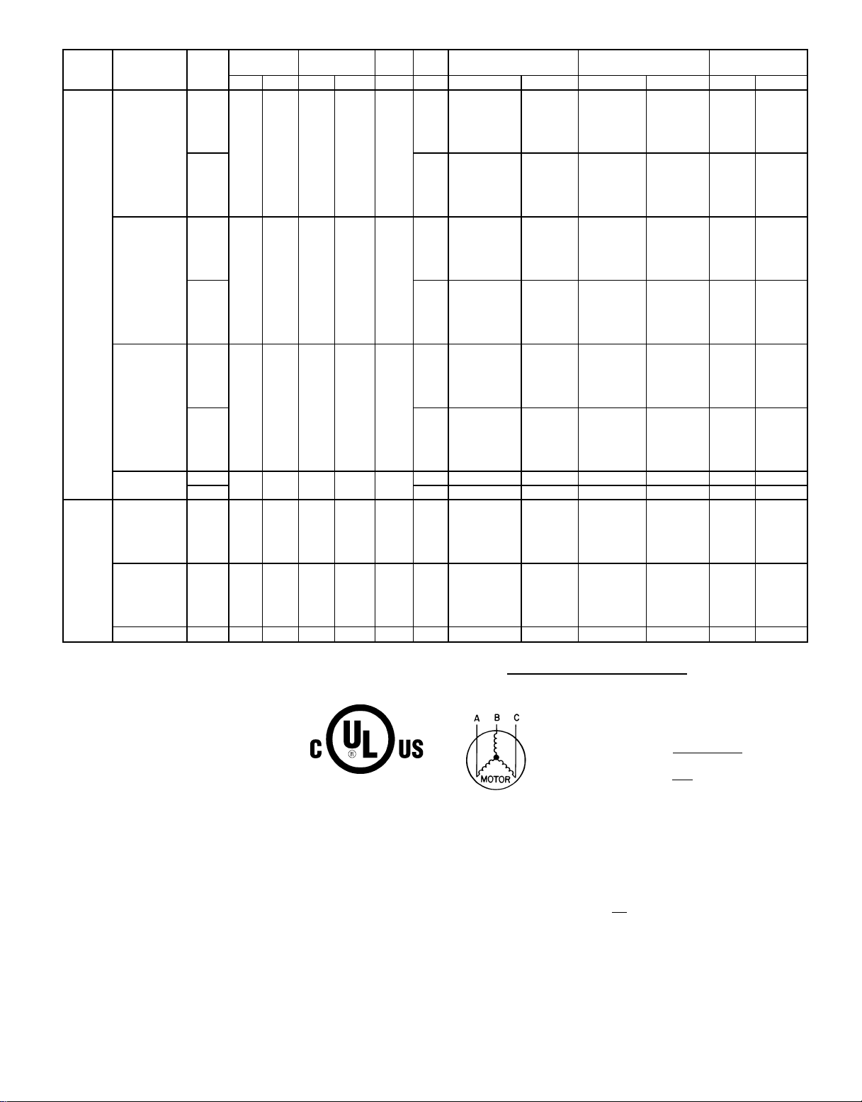
Table 2 — Electrical Data (Cont)
UNIT
558D
NOMINAL
V-PH-Hz
TYPE
VOLTAGE
IFM
RANGE
Min Max RLA LRA FLA FLA Nominal kW FLA MCA MOCP† FLA LRA
Std
208/230-1-60
187 254 28.8 147 1.4
Alt 8.8
Std
060
(5 Ton)
208/230-3-60
187 254 16.3 114 1.4
Alt 5.8
Std
460-3-60
414 508 7.4 64 0.8
Alt 2.6
575-3-60
Std
518 632 6.2 52 0.8\
Alt 2.6\ — — 11.2 15 12 59
208/230-3-60 Std 187 254 23.6 146.0 1.4 5.2
072
(6 Ton)
460-3-60 Std 414 508 10.6 73.0 0.8 2.6
575-3-60 Std 518 632 8.5 58.4 0.8\ 2.6\ — — 13.3 20 14 75
IMPORTANT: Optional, alternate evaporator-fan motor and drive are not available for
558D072 units. Contact your local representative for more information about fieldinstalled motors.
COMPR — Compressor
FLA — Full Load Amps
HACR — Heating, Air Conditioning and Refrigeration
IFM — Indoor (Evaporator) Fan Motor
LRA — Locked Rotor Amps
MCA — Minimum Circuit Amps
MOCP — Maximum Overcurrent Protection
NEC — National Electrical Code
OFM — Outdoor (Condenser) Fan Motor
RLA — Rated Load Amps
*Available for field-installed accessory heaters only. Heater capacity (kW) is based on
heater voltage of 208 v,240 v or 480 v. If power distribution voltage to unit varies from
rated heater voltage, heater kW will vary accordingly.
†Fuse or HACR circuit breaker.
**Used to determine minimum disconnect per NEC.
††Fusing single-point box provides the required branch circuit protection.
\Ampacities are based on 460 v. MCA and MOCP are based on 575 v.
NOTES:
1. In compliance with NEC requirements for multimotor and combination load equipment (refer to NEC Articles 430 and 440), the overcurrent protective device for the
unit shall be fuse or HACR breaker.
2. Unbalanced 3-Phase Supply Voltage
Never operate a motor where a phase imbalance in supply voltage is greater than
2%.
LEGEND
Use the following formula to determine the percent of voltage imbalance.
COMPR
(each)
OFM IFM ELECTRIC HEAT* POWER SUPPLY
DISCONNECT
SIZE**
— — 43.3/ 43.3 60/ 60 42/ 42 159/159
4.9/ 6.5 23.5/27.1 43.3/ 43.3 60/ 60 42/ 42 159/159
5.9
5.9
3.2
6.5/ 8.7 31.4/36.3 46.6/ 52.7 60/ 60 43/ 49 159/159
9.8/13.0 46.9/54.2 66.0/ 75.1 70/ 80†† 61/ 69 159/159
13.0/17.4 62.8/72.5 85.9/ 98.0 90/100†† 79/ 90 159/159
15.8/21.0 75.8/87.5 102.2/116.8 110/125†† 94/107 159/159
— — 46.2/ 46.2 60/ 60 45/ 45 162/162
4.9/ 6.5 23.5/27.1 46.2/ 46.2 60/ 60 45/ 45 162/162
6.5/ 8.7 31.4/36.3 49.9/ 55.9 60/ 60 46/ 52 162/162
9.8/13.0 46.9/54.2 69.3/ 78.3 70/ 80†† 64/ 72 162/162
13.0/17.4 62.8/72.5 89.2/101.3 90/110†† 82/ 93 162/162
15.8/21.0 75.8/87.5 105.5/120.0 110/125†† 97/110 162/162
— — 27.7/ 27.7 35/ 35 27/ 27 126/126
4.9/ 6.5 13.6/15.6 27.7/ 27.7 35/ 35 27/ 27 126/126
7.9/10.5 21.9/25.3 34.7/ 38.9 40/ 40 32/ 36 126/126
12.0/16.0 33.4/38.5 49.1/ 55.5 50/ 60 46/ 51 126/126
15.8/21.0 43.8/50.5 62.1/ 70.5 70/ 80†† 57/ 65 126/126
19.9/26.5 55.2/63.8 76.4/ 87.1 80/ 90†† 70/ 80 126/126
— — 26.8/ 26.8 40/ 40 27/ 27 125/125
4.9/ 6.5 13.6/15.6 26.8/ 26.8 40/ 40 27/ 27 125/125
7.9/10.5 21.9/25.3 35.3/ 39.5 45/ 45 32/ 36 125/125
12.0/16.0 33.4/38.5 49.6/ 56.0 60/ 60 45/ 51 125/125
15.8/21.0 43.8/50.5 62.6/ 71.1 70/ 80†† 57/ 65 125/125
19.9/26.5 55.2/63.8 77.0/ 87.6 80/100†† 70/ 80 125/125
— — 13.3 20 13 69
6.0 7.2 13.3 20 13 69
11.5 13.8 21.3 25 20 69
14.0 16.8 25.0 30 23 69
23.0 27.7 38.6 40 36 69
25.5 30.1 41.6 45 38 69
— — 12.7 20 12 70
6.0 7.2 12.7 20 12 70
11.5 13.8 21.0 25 19 70
14.0 16.8 24.8 30 22 70
23.0 27.7 38.3 45 35 70
25.0 30.1 41.3 45 38 70
3.2\ — — 11.8 15 12 57
— — 36.1/ 36.1 45/ 45 35/ 35 191/191
4.9/ 6.5 13.6/15.6 36.1/ 36.1 45/ 45 35/ 35 191/191
7.9/10.5 21.9/25.3 36.1/ 38.1 45/ 45 35/ 35 191/191
12.0/16.0 33.4/38.4 48.2/ 54.6 50/ 60 44/ 50 191/191
15.8/21.0 43.8/50.5 61.2/ 69.6 70/ 70†† 56/ 64 191/191
19.9/26.5 55.2/63.8 75.6/ 86.2 80/ 90†† 70/ 79 191/191
— — 16.7 20 16 90
6.0 7.2 16.7 20 16 90
11.5 13.8 20.5 25 19 90
14.0 16.8 24.3 25 22 90
23.0 27.8 37.8 40 35 90
25.5 30.7 41.6 45 38 90
% Voltage Imbalance
max voltage deviation from average voltage
= 100 x
Example: Supply voltage is 460-3-60.
NOTE: The 575-v units are Canada only.
Determine maximum deviation from average voltage.
(AB) 457 - 452=5v
(BC) 464 - 457=7v
(AC) 457 - 455=2v
Maximum deviation is 7 v.
Determine percent voltage imbalance.
% Voltage Imbalance = 100 x
This amount of phase imbalance is satisfactory as it is below the maximum allowable 2%.
IMPORTANT: If the supply voltage phase imbalance is more than 2%, contact your
local electric utility company immediately.
average voltage
AB = 452 v
BC = 464 v
AC = 455 v
Average Voltage =
457
= 1.53%
452 + 464 + 455
3
1371
=
3
= 457
7
—11—
Page 12
D. Accessory Installation
At this time, any required accessories should be installed on
the unit. Control wiring information is provided in the unit
wiring diagram. Refer to Accessory Installation Instructions
provided with accessory.
E. Optional Outdoor-Air Damper Installation
The outdoor-air hood and screen are attached to the basepan
at the bottom of the unit for shipping.
Assembly:
1. Determine quantity of ventilation required for building.
Record amount for use in Step 8.
2. Remove filter access panel by raising panel and swinging panel outward. Panel is now disengaged from track
and can be removed. No tools are required to remove filter access panel. Remove and save outdoor-air opening
panel and screws. See Fig. 15.
3. Separate hood and screen from basepan by removing the
4 screws and brackets securing them. Save all screws
and discard brackets.
4. Replace outdoor-air opening panel.
5. Place hood on front of outdoor air opening panel. See
Fig. 16 for hood details. Secure top of hood with the
4 screws removed in Step 3. See Fig. 17.
6. Remove andsave 6 screws (3 on each side) from sides of
the manual outdoor-air damper assembly.
7. Align screw holes on hood with screw holes on side of
manual outdoor-air damper assembly. See Fig. 16 and
17. Secure hood with 6 screws from Step 6.
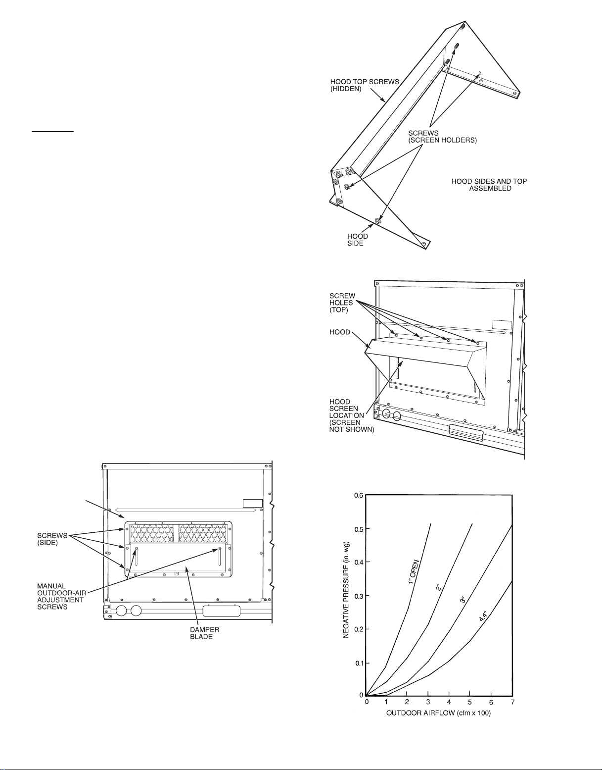
8. For proper quantity of ventilation air, adjust minimum
position setting of the damper blade by adjusting the
manual outdoor-air adjustment screws on the front of
the damper blade. See Fig. 15. Slide blade vertically until it is in the appropriate position determined by
Fig. 18. Tighten screws.
9. Remove and save 4 screws currently on sides of hood.
Insert screen. Secure screen to hood using the4 screws.
See Fig. 17.
Fig. 16 — Outdoor-Air Hood Details
OUTDOOR AIR
OPENING
PANEL
Fig. 15 — Damper Panel With Outdoor-Air
Damper Installed
Fig. 17 — Manual Outdoor-Air Damper With HoodAttached
Fig. 18 — Position Setting
—12—
Page 13

F. Optional Durablade Economizer
The optional economizer hood assembly is packaged and shipped
in the filter section. Damper blades and control boards are
installed at the factory and the economizer is shipped in the
vertical position.
NOTE: Horizontal discharge block-off plate is shipped with
the air hood package. If unit is to be used for vertical discharge application, discard this plate.
Assembly:
1. Determine if ventilation air is required for building. If
so, determine the minimum amount to be supplied by
each unit and record quantity of ventilation air needed
for use in Step 6.
2. Remove filter access panel by raising panel and s winging panel outward. Panel is now disengaged from track
and can be removed. No tools are required to remove
filter access panel. Remove outdoor-air opening panel.
Save panels and screws. See Fig. 19. Remove optional
outdoor-air damper hood package from filter section.
3. Assemble outdoor-air hood top and side plates as shown
in Fig. 20. Install seal strips on hood top and sides.
Put aside screen retainer and retainer screw for later
assembly. Do not attach hood to unit at this time.
4. To convert to horizontal discharge application:
a. Rotate the economizer 90 degrees until the econo-
mizer motor faces the condenser section (see Fig. 21).
b. Rotate barometric relief damper hinge 90 degrees. Baro-
metric relief damper should open vertically to operate properly.
c. Install horizontal discharge block-off plate over the
opening on the access panel. (Block-off plate MUST
be installed before installing hood assembly.) See
Fig. 22.
5. Insert economizer plug into economizer harness. Remove tape from barometric relief damper. See Fig. 23.
6. If ventilation air is not required, proceed to Step 7. If
ventilation air is required, determine the minimum position setting for required airflow. See Fig. 24. Adjust
minimum position setting by adjusting the screws on
the position setting bracket. Slide bracket until the top
screw is in the position determined by Fig. 24. Tighten
screws.
7. Remove tape from outdoor-air thermostat (OAT). Fasten OAT to inside of hood usingscrews and speed clips
provided (see Fig. 25). Make sure OAT terminals are
positioned up.
8. Replace outdoor-air opening panel using screws from
Step 2. Replace filter access panel. Ensure the filter
access panel slides along the tracks and is securely
engaged.
9. Fasten hood top and side plate assembly (Fig. 20) to
outdoor-air opening panel with screws provided.
10. Place knob, supplied with economizer, on OAT. See
Fig. 25. Set for 3° F below indoorroom thermostat setting. If accessory enthalpy control (EC) is used in place
of OAT, see instructions shipped with EC for installation and adjustment (see Fig. 25).
11. Connect OAT per Fig. 26.
Fig. 19 — Typical Access Panel Locations
Fig. 20 — Outdoor-Air Hood Details
12. Slide outdoor-air inlet screen into screen track on hood
side plate. While holding screen in place, fasten screen
retainer to hood using screws provided.
NOTE: Refer to Fig. 27 for economizer barometric relief damper
characteristics.
G. Optional PARABLADE Economizer
The optional PARABLADEeconomizer hood assembly is packaged and shipped in the filter section. Damper blades and
control boards are installed at the factory and the economizer is shipped in the vertical discharge position.
NOTE: Horizontal discharge block-off plate is shipped with
the air hood package. The PARABLADE economizer can only
be used for vertical discharge applications. Discard this plate.
—13—
Page 14

ECONOMIZER
CONTROL
BOARD
BAROMETRIC
RELIEF
DAMPER
ECONOMIZER
PLUG
ECONOMIZER
MOTOR
Fig. 21 — Horizontal Durablade Economizer Installation
(90 Degree Rotation)
BLOCK-OFF PLATE
Fig. 22 — Horizontal Discharge Block-Off Plate
ECONOMIZER
CONTROL
BOARD
ECONOMIZER
PLUG
WIRING
HARNESS
BAROMETRIC
RELIEF DAMPER
ECONOMIZER
MOTOR
TOP
SCREW
Example:
Given:
Negative Pressure ............................0.2in.wg
Outdoor Air ..................................900cfm
Determine — Setting—5in.
Fig. 24 — Durablade Economizer Minimum Position Setting
Assembly
1. Determine if ventilation air is required in building. If
so, determine the minimum amount to be supplied by
each unit and record quantity of ventilation air needed
for use in Step 5.
2. Remove filter access panel by raising panel and swinging panel outward. Panel is now disengaged from track
and can be removed. No tools are required to remove
filter access panel. Remove outdoor-air opening panel.
Save panels and screws. See Fig. 19.
3. Assemble outdoor-air hood top and side plates as shown
in Fig. 20. Install seal strips on hoop top and sides.
Put aside screen retainer and retainer screw for later
assembly. Do not attach hood to unit at this time.
4. Insert economizer plug into economizer harness. Remove tape from barometric relief damper. See Fig. 28.
5. If ventilationis not required, proceed toStep 6. If ventilation air is required, perform the following:
a. Make sure the factory-installed jumper is in place
across terminals P and P1 on the economizer logic
module. T and T1 should be disconnected during
adjustment.
b. The 2 potentiometers with slots for adjustment are
located on the face of the economizer logic module.
Turn the lower potentiometer fully clockwise. The
dampers should be fully closed. Turn the potentiometer gradually counterclockwise until the desired position is reached.
c. Connect T and T1 to the 24V power supply.
POSITION SETTING
BRACKET
Fig. 23 — Durablade Economizer Installed in Unit
—14—
Page 15

0.90
0.80
0.70
0.60
0.50
0.40
0.30
PRESSURE DROP (in. wg)
0.20
0.10
REV. B
CONTACTS SHOWN IN HIGH ENTHALPY
OR UNPOWERED STATE
B
198818A
C
TR
D
S
S
O
5
ENTHALPY
3
TR
24VAC
2
CONTROL
TR1
1
MINIMUM
POSITION
OPEN
1
3
T
P
2
T1
4
P1
CONTACT RATINGS: 1.5A RUN, 3.5A IN
RUSH AT 24VAC
%
H
U
M
I
D
I
T
Y
90
70
60
30
10
CW–SETPOINTS–CCW
D
50
DAMPER
C
OUTDOOR TEMP.
OPEN
55
B
A
60
65
70
75
°F
3 mA MIN. AT 11 VDC
DAMPER
CLOSED
80
85
97-3672
REV.
Fig. 25 — Outdoor-Air Thermostat/
Enthalpy Control Installation
OAT — Outdoor-Air Thermostat
NOTE: See unit wiring diagram for details.
Fig. 26 — Wiring Connections for Outdoor-Air Thermostat
0.00
200 300 400
100
500 600
700
800
CFM
Fig. 27 — Durablade Economizer Barometric Relief
Damper Characteristics
d. After installation is complete, calculate the mini-
mum airflow across the economizer.Tocalculate the
minimum airflow, the following data is needed:
total cfm (cfm
temperature of the return air (T
ture of the entering outside air (T
), temperature of the total cfm (T3),
3
), and tempera-
2
). Cfm1is the
1
outside air cfm, which will be the minimum airflow.
Insert the data into the following equations:
(cfm1)+T2(cfm2)
T
1
cfm
3
=T
3
cfm2= (cfm3− cfm1)
Therefore:
T1(cfm1)+ T2(cfm3− cfm1)
cfm
3
=T
3
Use this equation to determine cfm1, which is the
minimum airflow across the economizer.
cfm1=
(T
3−T2
(T
1−T2
) cfm
3
)
If cfm1does not match the desired minimum airflow from Step 1, readjust the minimum position
setting screw.
6. Determine the enthalpy changeover set point from
Fig. 28. The enthalpy changeover set point should be
set to return the outdoor air damper to the minimum
position when enthalpy rises above the set point. The
settings are A, B, C, and D. Set the enthalpy changeover
per the setting in Fig. 29.
7. Replace outdoor-air opening panel using screws from
Step 2. Replace filter access panel. Ensure the filter
access panel slides along the tracks and is securely engaged. See Fig. 30.
8. Fasten hood top and side plate assembly (Fig. 31) to
outdoor-air opening panel with screws provided.
9. Slide outdoor-air inlet screen into screen track on hood
side plate. While holding screen in place, fasten screen
retainer to hood using screws provided. See Fig. 32.
NOTE: Refer to Fig. 33 for PARABLADE economizer barometric relief damper characteristics.
—15—
Page 16

Fig. 28 — PARABLADE Economizer Installed in Unit
0.90
0.80
0.70
0.60
0.50
0.40
0.30
0.20
0.10
0.00
100
200
300
400
500
600 700
800
CFM
PRESSURE DROP (in. wg)
Fig. 31 — Outdoor-Air Hood Installed On Unit
CONTROL POINT
F (C) APPROX.
A 73 (23)
B 70 (21)
C 67 (19)
D 63 (17)
AT 50% RH
CONTROL
CURVE
RH — Relative Humidity
Fig. 29 — Enthalpy Settings for PARABLADE Economizer
Fig. 32 — Filter Installed on Outdoor-Air Hood
Fig. 30 — Panels Reinstalled On Unit
Fig. 33 — PARABLADE Economizer Barometric
Relief Damper Characteristics
—16—
Page 17

PRE-START-UP
WARNING:
ings could result in serious personal injury:
1. Follow recognized safety practices and wear protective goggles when checking or servicing refrigerant system.
2. Do not operate compressor or provide any electric
power to unit unless compressor terminal cover is
in place and secured.
3. Do not remove compressor terminal cover until all
electrical sources have been disconnected.
4. Relieve all pressure from system before touching
or disturbing anything inside terminal box if
refrigerant leak is suspected around compressor
terminals.
5. Never attempt to repair soldered connection while
refrigerant system is under pressure.
6. Do not use torch to remove any component. System contains oil and refrigerant under pressure.
To remove a component, wear protective goggles
and proceed as follows:
a. Relieve all pressure from system.
b. Cut component-connecting tubing with tubing
c. Carefully unsweat remaining tubing stubs when
Proceed as follows to inspect and prepare the unit for initial
start-up:
1. Remove all access panels.
2. Read and follow instructions on all WARNING, CAUTION and INFORMATION labels attached to, or shipped
with, unit.
3. Make the following inspections:
a. Inspect for shipping and handling damages such as
broken lines, loose parts, disconnected wires, etc.
b. Inspect for oil at all refrigerant tubing connections
and on unit base. Detecting oil generally indicates a
refrigerant leak. Leak-test all refrigerant tubing connections using electronic leak detector, halide torch,
or liquid-soap solution. If refrigerant leak is detected, see Refrigerant Leaks section on page 30.
c. Inspect all field- and factory-wiring connections. Be
sure that connections are completed and tight.
d. Inspect coil fins. If damaged during shipping and han-
dling, carefully straighten fins with a fin comb.
4. Verify the following conditions:
a. Make sure that condenser-fan blade is positioned cor-
rectly in fan orifice. Blades should clear fan motor
and fan orifice ring.
b. Make sure that air filters are in place.
c. Make sure that condensate drain pan and trap are
filled with water to ensure proper drainage.
d. Make sure that all tools and miscellaneous loose parts
have been removed.
5. Compressors are internally spring mounted. Do not loosen
or remove compressor holddown bolts.
6. Each unit system has 4 Schrader-type gage ports: one
on the suction line, one on the liquid line and two on
the compressor discharge line. Be sure that caps on the
ports are tight.
Unit is now ready for initial start-up.
Failure to observe the following warn-
cutter and remove component from unit.
necessary. Oil can ignite when exposedto torch
flame.
START-UP
I. HEATING SECTION START-UP AND ADJUSTMENTS
CAUTION:
in Pre-Start-Up section on this page before starting unit.
Do not jumper any safety devices when operating the unit.
A. Checking Heating Control Operation
Start and check the unit for proper heating control operation
as follows:
1. Turn on unit electrical supply.
2. Set system switch selector at HEATposition and fan switch
at AUTO. or ON position. Set heating temperature
lever above room temperature.
3. The evaporator fan will start immediately, and electric
heater will be energized.
4. Check for heating operation by verifying that unit supply outlets are functional.
5. The evaporator fan and heaters will turn off after thermostat temperature is satisfied.
B. Heating Sequence of Operation
Room thermostat calls for heat, closing circuit between R and
W1 24-v control terminals. Power to terminal R is supplied
through the 24-v transformer, which is internally protected
against overload. The 24-v power energizes the indoor (evaporator) fan relay (IFR). The IFR closes normally open contacts
2 to 4, which energize the indoor (evaporator) fan contactor
(IFC) and the electric heat contactor, and start the indoor (evaporator) fan motor (IFM). There is no time delay in the start-up
of the IFM.
When the call for heat is satisfied, then the R to W1 circuit is
opened and the IFR and IFC are deenergized.
Additional information on economizer operating in the heating only mode is provided in Ventilation Sequence section on
page 27.
C. Limit Switches
The heating limit switches (LS) are normally closed. If the
leaving-air temperature exceeds the maximum allowable temperature, one of the limit switches will open, breaking the
power circuit to the heater. This causes the heater to shut
down immediately. Check the air quantity to ensure there is
sufficient airflow.
If unit does not energize, reset the normally closed manual
limit switch (LSM). The LSM reset button is located on the
fan housing, and will only open in the event of a fan failure.
D. Airflow and Temperature Rise
The heating operation airflow must produce a temperature
rise that falls within the approved cfm range (300to 500 cfm
per 12,000 Btuh cooling).
Refer to Indoor Airflow and Airflow Adjustments section on
page 19 to adjust heating airflow where required.
E. Safety Check of Limit Control
Amanual reset limit control is located on the evaporator fan.
The control shuts off the unit in the event of fan failure.
Complete the required procedures given
—17—
Page 18

II. COOLING SECTION START-UP AND ADJUSTMENTS
CAUTION:
in the Pre-Start-Up section on page 17 before starting
the unit.
Do not jumper any safety devices when operating the
unit.
Do not operate the compressor when the outdoor temperature is below 25 F (unless accessory low ambient
kit is installed).
Do not rapid-cycle the compressor.Allow 5 minutes between ‘‘on’’ cycles to prevent compressor damage.
A. Checking Cooling Control Operation
Start and check the unit for proper cooling control operation
as follows:
1. Place room thermostat SYSTEM switch in OFF position. Observe that blower motor starts when FAN switch
is placed in ON position and shuts down when FANswitch
is placed in AUTO. position.
2. Place SYSTEM switch in COOL position and FAN switch
in AUTO. position. Set cooling control below room temperature. Observe that compressor, condenser fan motor and evaporator-fan motor start. Observe that cooling cycle shuts down when control setting is satisfied.
3. When using an auto-changeover room thermostat, place
both SYSTEM and FAN switches in AUTO. positions.
Observe that unit operates in Heating mode when temperature control is set above room temperature and operates in Cooling mode when temperature control is set
below room temperature.
B. Checking and Adjusting Refrigerant Charge
The refrigerant system is fully charged with R-22 refrigerant, tested and factory-sealed.
NOTE: Adjustment of the refrigerant charge is not required
unless the unit is suspected of not having the proper R-22
charge. This unit uses charging charts to determine proper
charge. See Refrigerant Charge section on page 30 for further details.
C. Unit Controls
All compressors have the following internal-protection
controls:
1. High-Pressure Relief Valve — This valve (internal to the
compressor) opens when the pressure differential between the low and high sides becomes excessive and will
automatically reset when pressure returns to normal.
2. Compressor Overload — This overload interrupts power
to the compressor when either the current or internal
temperature becomes excessive, and automatically resets when the internal temperature drops to a safe level.
This overload may require up to 60 minutes (or longer)
to reset; therefore, if the internal overload is suspected
of being open, disconnect the electrical power to the unit
and check the circuit through the overload with an ohmmeter or continuity tester.
D. Compressor Rotation
On 3-phase units with scroll compressors, it is important to
be certain compressor is rotating in the proper direction. To
determine whether or not compressor is rotating in the proper
direction:
1. Connect service gages to suction and discharge pressure fittings.
2. Energize the compressor.
Complete the required procedures given
3. The suction pressure should drop and the discharge pressure should rise, as is normal on any start-up.
If the suction pressure does not drop and the discharge pressure does not rise to normal levels:
1. Note that the evaporator fan is probably also rotating
in the wrong direction.
2. Turn off power to the unit.
3. Reverse any two of the unit power leads.
4. Reapply power to the compressor.
The suction and discharge pressure levels should now move
to their normal start-up levels.
NOTE: When the compressor is rotating in the wrong direction, the unit makes an elevated level of noise and does not
provide cooling.
E. Cooling Sequence of Operation
Without Economizer
Room thermostat calls for cooling. Circuit closes between
24-v control circuit terminals R and Y1 and terminals R and
G. Power to terminal R is supplied through the 24-v transformer (transformer is internally protected against overload). Terminal G energizes the indoor (evaporator) fan contactor (IFC) through normally closed contacts T and B of the
time-delay relay (TDR) and the evaporator fan starts.
The 24-v power through terminal Y1 energizes the compressor contactor (C), starting the compressor and condenser fan.
When the thermostat is satisfied, C1 is deenergized and the
compressor and OFM shut off. After a 30-second delay on
036-060 units, the IFM shutsoff. If the thermostat fanselector switch is in the ON position, the evaporator motor will
run continuously.
Cooling, Units with Durablade Economizer
When the outdoor-air temperature is above the outdoor-air
thermostat (OAT) setting and the room thermostat calls for
cooling, compressor contactor is energized to start compressor and the outdoor (condenser) fan motor (OFM). The indoor
(evaporator) fan motor (IFM) is energied and the economizer
damper moves to the minimum position. After the thermostat is satisfied, there is a 30-second delay before the evaporator fan turns off. The damper then moves to the fully closed
position. When using continuous fan, the damper moves to
the minimum position.
When the outdoor-air temperature is below the OAT setting
and the thermostat calls for cooling, the economizer damper
moves to the minimum position. If the supply-air temperature is above 57 F,the damper continues to open until it reaches
the fully open position or until the supply-air temperature
drops below 52 F.
When the supply-air temperature falls to between 57 F and
52 F, the damper will remain at an intermediate open position. If the supply-air temperature falls below 52 F,the damper
will modulate closed until it reaches the minimum position
or until the supply-air temperature is above 52 F. When the
thermostat is satisfied, the damper moves to the fully closed
position when using AUTO. fan or to the minimum position
when using a continuous fan.
If the outdoor air alone cannot satisfy the cooling requirements of the conditioned space, economizer cooling is integrated with mechanical cooling, providing two stages of cooling. The compressor and the condenser fan will be energized
and the position of the economizer damper will be determined by the supply-air temperature. When the second stage
—18—
Page 19

of cooling is satisfied, the compressor and OFM will be deenergized. The damper position will be determined by the supplyair temperature. When the first stage of cooling is satisfied,
there is a 30-second delay before the evaporator fan shuts
off.The damper then moves to the fully closed position. When
using a continous fan, the damper moves to the minimum
position. Additional information on economizer operation is
provided in the Ventilation Sequence section on page 27.
Cooling, Units With PARABLADE Economizer
When the outdoor-air is above the enthalpy control setting,
and the room thermostat calls for cooling, the compressor contactor is energized to start the compressor and the outdoor
(condenser) fan motor. The indoor (evaporator) fan motor is
energized and the economizer damper moves to the minimum position. After the room thermostat is satisfied the damper
will spring return to the fully closed position.
When the outdoor-air is below the enthalpy control setting
and the thermostat calls for cooling, the economizer outdoorair damper is opened proportionally to maintain between 50
and 56 F at the mixed-air sensor. If outside air alone cannot
satisfy the cooling requirements, economizer cooling is integrated with mechanical cooling. When the room thermostat
is satisfied, the damper will spring return to the full closed
position. Additional information on economizer operation is
provided in the Ventilation Sequence section on page 27.
Time Guardt II Device
If the unit is equipped with accessory Time Guard II recycle
timer,the unit will delay 5 minutes between compressor starts.
Controls Kit
Loss-of-Charge/Low-Pressure Switch (LPS) — When the liq-
uid line pressure drops below 7 psig, the LPS opens 24-v power
to the compressor contactor and stops the compressor. When
the pressure reaches 22 psig, the switch resets and the compressor is allowed to come back on.
High-Pressure Switch (HPS) — When the refrigerant highside pressure reaches 428 psig, the HPS opens 24-v power to
the compressor contactor and stops the compressor.When the
pressure drops to 320 psig, the switch resets and the compressor is allowed to restart.
Freeze-Protection Thermostat (FPT) — When the evaporatorcoil leaving refrigerant temperature drops below 30 F, the FPT
opens 24-v power to the compressor contactor and stops the
compressor.When the leaving refrigerant temperature warms
to 45 F, the switch resets and the compressor is allowed to
restart.
III. INDOOR AIRFLOW AND AIRFLOW ADJUSTMENTS
CAUTION:
For cooling operation, the recommended
airflow is 300 to 500 cfm per each 12,000 Btuh of rated
cooling capacity.For heating operation, the airflow must
produce a temperature rise that falls within the range
stamped on the unit rating plate.
Adjust evaporator-fan speed to meet jobsite conditions.
Table3 shows fan rpm at motor pulley settings. Table 4 shows
maximum amp draw of belt drive motor. Refer to Tables 5-18
to determine fan speed settings.
A. Direct Drive Motors
The evaporator-fan motor factory speed setting is shown on
label diagram affixed to base unit. If other than factory setting is desired, refer to label diagram for motor reconnection.
Table 3 — Fan Rpm at Motor Pulley Settings*
UNIT
558D
036† 1090 1055 1025 990 960 925 890 860 825 795 760
048† 1185 1150 1115 1080 1045 1015 980 945 910 875 840
060† 1300 1260 1220 1180 1140 1100 1060 1020 980 940 900
072** 1460 1420 1380 1345 1305 1265 1225 1185 1150 1110 1070
*Approximate fan rpm shown.
†Indicates alternate motor and drive package.
**Indicates standard motor and drive package.
0
1
⁄
2
11
MOTOR PULLEY TURNS OPEN
1
⁄
2
22
1
⁄
2
33
1
⁄
2
44
1
⁄
2
5
—19—
Page 20

Table 4 — Motor Data
UNIT
558D
EVAPORATOR-FAN
MOTOR
MAXIMUM MAXIMUM
CONTINUOUS OPERATING AMP
BHP* WATTS* DRAW
UNIT
VOLTAGE
MAXIMUM
208/230 2.9
Std .34 440
036
Alt 1.00 1000
460 1.4
575 1.4
208/230 5.1
460 2.3
575 2.3
208/230 3.7
Std .75 850
048
Alt 1.00 1000
460 1.9
575 1.9
208/230 5.1
460 2.3
575 2.3
208/230 6.2
Std 1.20 1340
460 3.4
575 3.4
060
Alt
1.3 1750 208/230† 7.6
208/230** 6.1
2.4 2120
460 2.7
575 2.7
208/230 6.1
072 Std 2.40 2120
460 2.7
575 2.7
LEGEND
Bhp — Brake Horsepower
*Extensive motor and electrical testing on these units ensures that the full range of the motors can be
utilized with confidence. Using your fan motors up to the ratings shown in this table will not result in
nuisance tripping or premature motor failure. Unit warranty will not be affected.
†Single-Phase motor.
**3-phase motor.
Table 5 — 558D036 Air Delivery — Vertical Discharge Units (Standard Motor)
AIRFLOW
(Cfm)
900 0.67 253 0.68 277 0.69 307 0.69 363
1000 0.60 270 0.61 292 0.61 321 0.63 374
1100 0.55 287 0.56 307 0.57 335 0.58 385
1200 0.51 304 0.51 323 0.52 349 0.53 397
1300 0.45 321 0.46 338 0.46 364 0.47 408
1400 0.38 338 0.41 354 0.43 378 0.43 420
1500 0.34 355 0.36 369 0.38 392 0.39 431
208 v 230, 460, 575 v 208 v 230, 460, 575 v
ESP Watts ESP Watts ESP Watts ESP Watts
Low Speed High Speed
LEGEND
ESP — External Static Pressure (in. wg)
NOTES:
1. Values include losses for filters, unit casing, and wet coils.
2. Extensive motor and electrical testing on these units ensures that the full range of the motor can be
utilized with confidence. Using your fan motors up to the wattage ratings shown will not result in
nuisance tripping or premature motor failure. Unit warranty will not be affected. For additional information on motor performance, refer to Table 4.
3. Use of a field-supplied motor may affect wire sizing. Contact your distributor to verify.
4. To convert watts to bhp:
bhp =
watts input x motor efficiency
746
Motor efficiency = .63
STANDARD DIRECT DRIVE MOTOR
—20—
Page 21

Table 6 — 558D036 Air Delivery — Vertical Discharge Units (Alternate Motor)
ALTERNATE BELT DRIVE MOTOR
AIRFLOW
(Cfm)
900 581 119 673 179 736 219 805 249 865 288 911 338 957 388 988 428
1000 644 189 709 219 782 279 835 298 900 348 937 378 992 438 1039 487
1100 687 219 746 259 806 298 867 348 929 398 964 398 1013 487 1068 547
1200 733 259 785 318 843 348 903 408 960 467 994 497 1045 557 1090 637
1300 754 288 826 378 891 428 942 477 991 527 1047 597 1075 637 1122 696
1400 810 348 868 448 937 507 984 567 1032 617 1067 666 1110 726 1160 766
1500 841 418 911 527 985 607 1029 656 1073 716 1109 766 1150 816 1190 855
AIRFLOW
(Cfm)
900 1039 448 1061 487 1083 527 1105 567
1000 1061 507 1086 547 1111 587 1136 627
1100 1090 577 1109 607 1127 637 1145 666
1200 1109 647 1156 676 1203 706 1250 736
1300 1152 716 1190 756 1228 796 1266 836
1400 1181 806 1237 845 1293 885 1349 925
1500 1225 895 1271 945 1317 995 1363 1044
NOTES:
1. Boldface indicates a field-supplied drive is required. (See Note 7.)
2. indicates field-supplied motor and drive are required.
3.
4. Maximum usable watts input is 1000. Extensive motor and electrical testing on these units ensures that the full range of the motor can be
5. Values include losses for filters, unit casing, and wet coils.
6. Use of a field-supplied motor may affect wire sizing. Contact your distributor to verify.
7. Alternate motor drive range: 760 to 1090 rpm. All other rpms require field-supplied drive.
8. To convert watts to bhp:
indicates maximum usable watts of a factory-supplied motor.
utilized with confidence. Using your fan motors up to the wattage ratings shown will not result in nuisance tripping or premature motor
failure. Unit warranty will not be affected. For additional information on motor performance, refer to Table 4.
watts input x motor efficiency
bhp =
Motor efficiency = .75
0.1 0.2 0.3 0.4 0.5 0.6 0.7 0.8
Rpm Watts Rpm Watts Rpm Watts Rpm Watts Rpm Watts Rpm Watts Rpm Watts Rpm Watts
ALTERNATE BELT DRIVE MOTOR
External Static Pressure (in. wg)
0.9 1.0 1.1 1.2
Rpm Watts Rpm Watts Rpm Watts Rpm Watts
746
External Static Pressure (in. wg)
Table 7 — 558D048 Air Delivery — Vertical Discharge Units (Standard Motor)
AIRFLOW
(Cfm)
1200 0.93 458 0.94 506 0.94 572 0.99 632
1300 0.86 471 0.87 521 0.87 589 0.92 651
1400 0.78 503 0.79 556 0.79 616 0.87 681
1500 0.70 536 0.73 593 0.73 631 0.80 698
1600 0.61 557 0.64 616 0.66 654 0.76 723
1700 0.51 584 0.54 646 0.58 678 0.68 750
1800 0.40 610 0.44 674 0.51 698 0.63 772
1900 0.29 629 0.37 696 0.46 720 0.56 796
2000 0.25 651 0.30 720 0.39 744 0.50 823
ESP — External Static Pressure (in. wg)
NOTES:
1. Values include losses for filters, unit casing, and wet coils.
2. Extensive motor and electrical testing on these units ensures that the full range of the motor can be utilized with
confidence. Using your fan motors up to the wattage ratings shown will not result in nuisance tripping or premature
motor failure. Unit warranty will not be affected. For additional information on motor performance, refer to Table4.
3. Use of a field-supplied motor may affect wire sizing. Contact your distributor to verify.
4. To convert watts to bhp:
bhp =
Motor efficiency = .66
watts input x motor efficiency
208 v 230, 460, 575 v 208 v 230, 460, 575 v
ESP Watts ESP Watts ESP Watts ESP Watts
LEGEND
Low Speed High Speed
746
STANDARD DIRECT DRIVE MOTOR
—21—
Page 22

Table 8 — 558D048 Air Delivery — Vertical Discharge Units (Alternate Motor)
ALTERNATE BELT DRIVE MOTOR
AIRFLOW
(Cfm)
1200 542 168 616 221 678 278 739 336 842 462 886 525 929 588 1008 704
1300 576 210 644 263 704 326 764 389 867 525 910 588 952 651 1029 788
1400 610 252 673 315 732 378 791 441 889 578 933 651 976 725 1052 826
1500 646 294 704 368 761 436 818 504 912 641 957 720 1001 777 1076 905
1600 681 347 735 420 790 494 845 567 920 695 931 772 1023 848 1100 995
1700 718 410 768 483 836 562 873 641 965 777 1005 853 1045 930 1124 1084
1800 754 473 801 557 851 641 900 725 992 858 1032 940 1071 1022 1147 1174
1900 791 546 836 630 832 720 828 809 1019 950 1058 1037 1097 1124 1169 1263
2000 828 630 870 714 864 809 858 904 1046 1053 1085 1139 1124 1237 1194 1373
AIRFLOW
(Cfm)
1200 1052 762 1096 820 1134 835 1203 885 1242 969
1300 1065 846 1101 904 1174 1040 1229 1100 1277 1029
1400 1087 890 1121 918 1183 1042 1255 1167 1305 1190
1500 1111 980 1145 1014 1208 1138 1274 1272 1337 1350
1600 1134 1069 1168 1100 1232 1253 1291 1396 1350 1558
1700 1158 1164 1192 1196 1255 1358 1314 1511 1370 1738
1800 1182 1263 1217 1301 1279 1473 1381 1635 1393 1907
1900 1205 1363 1240 1406 1303 1588 1408 1769 1417 2068
2000 1228 1472 1262 1511 1327 1702 1436 1894 1440 2229
NOTES:
1. Boldface indicates a field-supplied drive is required. (See Note 7.)
2. indicates field-supplied motor and drive are required.
3.
4. Maximum usable watts input is 1000. Extensive motor and electrical testing on these units ensures that the full range of the motor can be
5. Values include losses for filters, unit casing, and wet coils.
6. Use of a field-supplied motor may affect wire sizing. Contact your distributor to verify.
7. Alternate motor drive range: 840 to 1185 rpm. All other rpms require field-supplied drive.
8. To convert watts to bhp:
indicates maximum usable watts of a factory-supplied motor.
utilized with confidence. Using your fan motors up to the wattage ratings shown will not result in nuisance tripping or premature motor
failure. Unit warranty will not be affected. For additional information on motor performance, refer to Table 4.
watts input x motor efficiency
bhp =
Motor efficiency = .75
0.1 0.2 0.3 0.4 0.6 0.7 0.8 1.0
Rpm Watts Rpm Watts Rpm Watts Rpm Watts Rpm Watts Rpm Watts Rpm Watts Rpm Watts
ALTERNATE BELT DRIVE MOTOR
External Static Pressure (in. wg)
1.1 1.2 1.4 1.6 1.8
Rpm Watts Rpm Watts Rpm Watts Rpm Watts Rpm Watts
746
External Static Pressure (in. wg)
Table 9 — 558D060 Air Delivery — Vertical Discharge Units (Standard Motor)
AIRFLOW
(Cfm)
1500 0.88 750 1.20 791 1.19 782 1.36 845 1.38 875 1.44 949
1600 0.68 780 1.04 824 1.04 821 1.22 883 1.25 913 1.33 988
1700 0.51 810 0.89 857 0.89 861 1.09 921 1.13 950 1.22 1027
1800 0.35 839 0.73 891 0.74 900 0.96 959 1.00 988 1.11 1066
1900 0.26 873 0.58 924 0.59 940 0.86 997 0.88 1025 1.00 1105
2000 0.18 905 0.42 957 0.44 979 0.73 1035 0.78 1063 0.92 1144
2100 0.08 940 0.27 990 0.29 1018 0.59 1073 0.63 1101 0.81 1183
2200 — — 0.19 1023 0.19 1035 0.46 1111 0.49 1138 0.69 1222
2300 — — 0.11 1056 0.11 1076 0.34 1149 0.41 1176 0.59 1261
2400 — — 0.03 1096 0.04 1113 0.19 1187 0.22 1213 0.43 1300
2500 — — — — — — 0.09 1225 0.12 1251 0.34 1340
ESP — External Static Pressure (in. wg)
NOTES:
1. Values include losses for filters, unit casing, and wet coils.
2. Extensive motor and electrical testing on these units ensures that the full range of the motor can be utilized with confidence. Using your
fan motors up to the wattage ratings shown will not result in nuisance tripping or premature motor failure. Unit warranty will not be affected. For additional information on motor performance, refer to Table 4.
3. Use of field-supplied motor may affect wire sizing. Contact your distributor to verify.
4. To convert watts to bhp:
bhp =
Motor efficiency = .67
watts input x motor efficiency
208 v 230, 460, 575 v 208 v 230, 460, 575 v 208 v 230, 460, 575 v
ESP Watts ESP Watts ESP Watts ESP Watts ESP Watts ESP Watts
LEGEND
Low Speed Medium Speed High Speed
746
STANDARD DIRECT DRIVE MOTOR
—22—
Page 23

Table 10 — 558D060 Air Delivery — Vertical Discharge Units (Alternate Motor)
ALTERNATE BELT DRIVE MOTOR
AIRFLOW
(Cfm)
1500 730 347 789 409 896 542 990 685 1072 848 1153 1022 1221 1196 1256 1328 1280 1349 1320 1400
1600 770 409 826 470 931 623 1020 766 1101 930 1178 1114 1252 1298 1311 1482 1340 1615 1380 1645
1700 811 480 865 552 966 705 1051 858 1133 1032 1205 1206 1278 1400 1345 1604 1397 1799 1424 1931
1800 852 562 905 634 1002 797 1084 950 1163 1124 1235 1318 1303 1512 1371 1727 1433 1942 1480 2136
1900 894 552 945 736 1037 899 1119 1063 1194 1237 1266 1431 1330 1625 1396 1850 1460 2074 1517 2299
2000 936 756 984 838 1072 1001 1154 1185 1226 1359 1297 1564 1362 1768 1422 1983 1485 2207 1544 2453
2100 978 869 1024 950 1108 1124 1192 1318 1259 1502 1327 1696 1393 1911 1452 2126 1510 2361 1569 2606
2200 1021 991 1064 1073 1145 1247 1225 1461 1294 1656 1359 1850 1423 2064 1483 2289 1538 2514 1595 2769
2300 1064 1124 1104 1206 1183 1390 1260 1604 1330 1819 1392 2013 1454 2228 1515 2463 1569 2698 1622 2943
2400 1107 1267 1145 1349 1222 1482 1296 1768 1365 1983 1426 2197 1485 2412 1544 2647 1601 2902 1652 3137
2500 1150 1420 1186 1512 1262 1717 1331 1931 1400 2166 1461 2391 1518 2606 1575 2841 1631 3096 1684 3352
NOTES:
1. Boldface indicates a field-supplied drive is required. (See Note 7.)
2. indicates field-supplied motor and drive are required.
3.
4. Maximum usable watts input is 2120. Extensive motor and electrical testing on these units ensures that the full range of the motor can be
utilized with confidence. Using your fan motors up to the wattage ratings shown will not result in nuisance tripping or premature motor
failure. Unit warranty will not be affected. For additional information on motor performance, refer to Table 4.
5. Values include losses for filters, unit casing, and wet coils.
6. Use of a field-supplied motor may affect wire sizing. Contact your distributor to verify.
7. Alternate motor drive range: 900 to 1300. All other rpms require field-supplied drive.
8. To convert watts to bhp:
bhp =
Motor efficiency = .74
0.1 0.2 0.4 0.6 0.8 1.0 1.2 1.4 1.6 1.8
Rpm Watts Rpm Watts Rpm Watts Rpm Watts Rpm Watts Rpm Watts Rpm Watts Rpm Watts Rpm Watts Rpm Watts
indicates maximum usable watts of a factory-supplied motor.
watts input x motor efficiency
746
External Static Pressure (in. wg)
Table 11 — 558C072 Air Delivery — Vertical Discharge Units (Standard Motor)
STANDARD BELT DRIVE MOTOR
AIRFLOW
(Cfm)
1800 852 562 905 615 1002 739 1084 859 1163 998 1235 1156 1303 1318 1371 1499 1433 1638
1900 894 630 945 692 1037 818 1119 948 1194 1089 1266 1250 1330 1413 1396 1604 1460 1796
2000 936 708 984 771 1072 899 1154 1047 1226 1190 1297 1361 1362 1534 1422 1718 1485 1910
2100 978 795 1024 859 1108 998 1190 1156 1259 1310 1327 1473 1393 1656 1452 1840 1510 2041
2200 1021 891 1064 956 1145 1097 1225 1275 1294 1439 1359 1604 1423 1779 1483 1980 1538 2171
2300 1064 998 1104 1064 1183 1216 1260 1396 1330 1578 1392 1744 1454 1927 1515 2128 1569 2326
2400 1107 1114 1145 1182 1222 1353 1296 1534 1365 1718 1426 1901 1485 2084 1544 2283 1601 2459
2500 1150 1241 1186 1318 1262 1491 1331 1674 1400 1875 1461 2067 1518 2249 1575 2445 — —
2600 1193 1387 1228 1465 1301 1648 1367 1831 1435 2041 1497 2240 1552 2428 ————
2700 1237 1543 1269 1621 1341 1814 1404 1997 1471 2214 1532 2420 ——————
2800 1280 1718 1311 1796 1381 1989 1442 2180 1506 2394 — — ——————
2900 1324 1901 1354 1980 1420 2180 1481 2369 1542 2579 — — ——————
3000 1368 2093 1396 2171 1460 2369 1521 2571 ——————————
NOTES:
1. Boldface indicates field-supplied drive required. (See Note 7.)
2. indicates field-supplied motor and drive are required.
3.
4. Maximum usable watts input is 2120. Extensive motor and electrical testing on these units ensures that the full range of the motor can be
5. Values include losses for filters, unit casing and wet coils.
6. Use of a field-supplied motor may affect wire sizing. Contact your distributor to verify.
7. Standard motor drive range: 1070 to 1460. All other rpms require field-supplied drive.
8. To convert watts to bhp:
indicates maximum usable watts of a factory-supplied motor.
utilized with confidence. Using your fan motors up to the wattage ratings shown will not result in nuisance tripping or premature motor
failure. Unit warranty will not be affected. For additional information on motor performance, refer to Table 4.
watts input x motor efficiency
bhp =
Motor efficiency = .84
0.1 0.2 0.4 0.6 0.8 1.0 1.2 1.4 1.6
Rpm Watts Rpm Watts Rpm Watts Rpm Watts Rpm Watts Rpm Watts Rpm Watts Rpm Watts Rpm Watts
746
External Static Pressure (in. wg)
—23—
Page 24

Table 12 — 558D036 Air Delivery — Horizontal Discharge Units (Standard Motor)
AIRFLOW
(Cfm)
900 0.72 253 0.75 277 0.73 307 0.76 363
1000 0.67 270 0.69 292 0.70 321 0.71 374
1100 0.61 287 0.63 307 0.64 335 0.65 385
1200 0.57 304 0.58 323 0.56 349 0.59 397
1300 0.51 321 0.53 338 0.53 364 0.54 408
1400 0.44 338 0.46 354 0.47 378 0.48 420
1500 0.39 355 0.41 369 0.43 392 0.43 431
ESP — External Static Pressure (in. wg)
NOTES:
1. Values include losses for filters, unit casing, and wet coils.
2. Extensive motor and electrical testing on these units ensures that the full range of the motor can be utilized with
confidence. Using your fan motors up to the wattage ratings shown will not result in nuisance tripping or premature
motor failure. Unit warranty will not be affected. For additional information on motor performance, refer to Table4.
3. Use of a field-supplied motor may affect wire sizing. Contact your distributor to verify.
4. To convert watts to bhp:
bhp =
Motor efficiency = .63
watts input x motor efficiency
208 v 230, 460, 575 v 208 v 230, 460, 575 v
ESP Watts ESP Watts ESP Watts ESP Watts
LEGEND
Low Speed High Speed
746
STANDARD DIRECT DRIVE MOTOR
Table 13 — 558D036 Air Delivery — Horizontal Discharge Units (Alternate Motor)
ALTERNATE BELT DRIVE MOTOR
AIRFLOW
(Cfm)
900 526 70 584 99 656 139 734 219 818 269 875 269 924 308 953 348
1000 570 109 627 149 736 189 800 259 848 288 895 308 936 348 977 388
1100 614 149 670 189 758 229 812 288 863 308 914 348 960 388 1005 428
1200 658 189 710 229 780 279 840 318 889 358 938 398 988 448 1038 497
1300 703 239 752 269 808 318 868 368 916 408 963 448 1012 507 1061 557
1400 725 288 776 308 845 378 891 418 937 467 983 507 1027 557 1071 597
1500 755 328 816 378 870 428 924 477 969 527 1014 577 1056 627 1097 676
0.1 0.2 0.3 0.4 0.5 0.6 0.7 0.8
Rpm Watts Rpm Watts Rpm Watts Rpm Watts Rpm Watts Rpm Watts Rpm Watts Rpm Watts
External Static Pressure (in. wg)
ALTERNATE BELT DRIVE MOTOR
AIRFLOW
(Cfm)
900 989 388 1028 438 1074 487 1120 537
1000 1020 438 1064 477 1124 537 1185 597
1100 1052 487 1100 527 1163 587 1225 647
1200 1076 527 1136 577 1201 647 1266 716
1300 1090 607 1172 647 1239 716 1306 786
1400 1108 666 1208 706 1278 786 1347 865
1500 1117 696 1245 776 1315 865 1385 955
NOTES:
1. Boldface indicates a field-supplied drive is required. (See Note 4.)
2. Maximum usable watts input is 1000. Extensive motor and electrical testing on these units ensures that the full range of the motor can be
utilized with confidence. Using your fan motors up to the wattage ratings shown will not result in nuisance tripping or premature motor
failure. Unit warranty will not be affected. For additional information on motor performance, refer to Table 4.
3. Values include losses for filters, unit casing, and wet coils.
4. Alternate motor drive range: 760 to 1090 rpm. All other rpms require field-supplied drive.
5. To convert watts to bhp:
watts input x motor efficiency
bhp =
Motor efficiency = .75
0.9 1.0 1.1 1.2
Rpm Watts Rpm Watts Rpm Watts Rpm Watts
746
External Static Pressure (in. wg)
—24—
Page 25

Table 14 — 558D048 Air Delivery — Horizontal Discharge Units (Standard Motor)
AIRFLOW
(Cfm)
1200 0.93 458 0.97 506 1.04 572 1.09 632
1300 0.86 471 0.90 521 0.96 589 1.02 651
1400 0.78 503 0.84 556 0.90 616 0.96 681
1500 0.73 536 0.76 593 0.83 631 0.89 698
1600 0.67 557 0.70 616 0.75 654 0.82 723
1700 0.60 584 0.63 646 0.67 678 0.74 750
1800 0.51 610 0.54 674 0.62 698 0.69 772
1900 0.40 629 0.45 696 0.54 720 0.62 796
2000 0.32 661 0.33 731 0.47 744 0.54 823
ESP — External Static Pressure (in. wg)
NOTES:
1. Values include losses for filters, unit casing, and wet coils.
2. Extensive motor and electrical testing on these units ensures that the full range of the motor can be utilized with
confidence. Using your fan motors up to the wattage ratings shown will not result in nuisance tripping or premature
motor failure. Unit warranty will not be affected. For additional information on motor performance, refer to Table4.
3. Use of a field-supplied motor may affect wire sizing. Contact your distributor to verify.
4. To convert watts to bhp:
bhp =
Motor efficiency = .66
LEGEND
watts input x motor efficiency
208 v 230, 460, 575 v 208 v 230, 460, 575 v
ESP Watts ESP Watts ESP Watts ESP Watts
Low Speed High Speed
746
STANDARD DIRECT DRIVE MOTOR
Table 15 — 558D048 Air Delivery — Horizontal Discharge Units (Alternate Motor)
ALTERNATE BELT DRIVE MOTOR
AIRFLOW
(Cfm)
1200 514 158 590 210 657 263 723 315 828 441 876 510 924 578 999 674
1300 545 189 615 242 680 305 744 368 849 494 895 562 940 630 1025 756
1400 577 221 642 284 704 347 766 410 870 546 915 620 959 693 1042 828
1500 609 273 670 326 729 394 788 462 892 609 936 683 980 757 1060 899
1600 642 315 699 378 755 447 811 515 913 672 957 751 1001 830 1080 971
1700 675 378 728 441 782 510 836 578 935 746 979 825 1023 904 1101 1053
1800 709 431 759 504 810 578 860 651 957 820 1001 904 1044 988 1122 1134
1900 743 504 790 578 838 651 886 725 980 904 1023 993 1066 1082 1143 1237
2000 778 578 836 651 875 730 913 809 1004 988 1046 1082 1088 1177 1165 1339
0.1 0.2 0.3 0.4 0.6 0.7 0.8 1.0
Rpm Watts Rpm Watts Rpm Watts Rpm Watts Rpm Watts Rpm Watts Rpm Watts Rpm Watts
External Static Pressure (in. wg)
ALTERNATE BELT DRIVE MOTOR
AIRFLOW
(Cfm)
1200 1018 685 1036 695 1073 756 1109 794 1138 851
1300 1058 807 1090 858 1121 832 1159 918 1193 976
1400 1080 899 1118 971 1175 1014 1206 1042 1244 1138
1500 1098 981 1136 1063 1205 1138 1258 1243 1289 1282
1600 1117 1058 1153 1140 1224 1234 1287 1387 1337 1492
1700 1137 1139 1172 1226 1241 1320 1307 1492 1366 1655
1800 1157 1226 1192 1318 1258 1415 1323 1597 1385 1779
1900 1179 1328 1214 1420 1279 1511 1341 1702 1402 1894
2000 1200 1431 1235 1523 1300 1616 1361 1817 1419 2008
NOTES:
1. Boldface indicates a field-supplied drive is required. (See Note 7.)
2. indicates field-supplied motor and drive are required.
3.
4. Maximum usable watts input is 1000. Extensive motor and electrical testing on these units ensures that the full range of the motor can be
5. Values include losses for filters, unit casing, and wet coils.
6. Use of a field-supplied motor may affect wire sizing. Contact your distributor to verify.
7. Alternate motor drive range: 840 to 1185 rpm. All other rpms require field-supplied drive.
8. To convert watts to bhp:
indicates maximum usable watts of a factory-supplied motor.
utilized with confidence. Using your fan motors up to the wattage ratings shown will not result in nuisance tripping or premature motor
failure. Unit warranty will not be affected. For additional information on motor performance, refer to Table 4.
watts input x motor efficiency
bhp =
Motor efficiency = .75
1.1 1.2 1.4 1.6 1.8
Rpm Watts Rpm Watts Rpm Watts Rpm Watts Rpm Watts
746
External Static Pressure (in. wg)
—25—
Page 26

Table 16 — 558D060 Air Delivery — Horizontal Discharge Units (Standard Motor)
AIRFLOW
(Cfm)
1500 1.01 750 1.25 791 1.26 782 1.46 845 1.46 875 1.52 949
1600 0.82 780 1.09 824 1.11 821 1.32 883 1.33 913 1.41 988
1700 0.64 810 0.97 857 0.99 861 1.22 921 1.24 950 1.33 1027
1800 0.44 839 0.81 891 0.84 900 1.09 959 1.11 988 1.22 1066
1900 0.32 869 0.66 924 0.69 940 0.96 997 0.99 1025 1.11 1105
2000 0.21 899 0.47 957 0.51 979 0.80 1035 0.83 1063 0.97 1144
2100 0.13 929 0.32 990 0.36 1018 0.64 1073 0.71 1101 0.86 1183
2200 0.05 959 0.19 1023 0.21 1058 0.50 1111 0.58 1138 0.75 1222
2300 — — 0.08 1057 0.08 1097 0.34 1149 0.39 1176 0.57 1261
2400 — — — — — — 0.24 1187 0.29 1213 0.49 1300
2500 — — — — — — 0.15 1225 0.15 1251 0.34 1340
ESP — External Static Pressure (in. wg)
NOTES:
1. Values include losses for filters, unit casing, and wet coils.
2. Extensive motor and electrical testing on these units ensures that the full range of the motor can be utilized with confidence. Using your
fan motors up to the wattage ratings shown will not result in nuisance tripping or premature motor failure. Unit warranty will not be affected. For additional information on motor performance, refer to Table 4.
3. Use of field-supplied motor may affect wire sizing. Contact your distributor to verify.
4. To convert watts to bhp:
bhp =
Motor efficiency = .67
watts input x motor efficiency
208 v 230, 460, 575 v 208 v 230, 460, 575 v 208 v 230, 460, 575 v
ESP Watts ESP Watts ESP Watts ESP Watts ESP Watts ESP Watts
LEGEND
Low Speed Medium Speed High Speed
746
STANDARD DIRECT DRIVE MOTOR
Table 17 — 558D060 Air Delivery — Horizontal Discharge Units (Alternate Motor)
ALTERNATE BELT DRIVE MOTOR
AIRFLOW
(Cfm)
1500 658 276 722 337 840 470 937 603 1027 756 1108 920 1186 1104 1263 1328 1343 1615 1431 1829
1600 693 327 754 388 867 531 963 664 1052 828 1130 991 1205 1175 1278 1380 1350 1645 1424 1921
1700 729 388 787 450 895 593 991 746 1075 899 1154 1083 1226 1257 1296 1451 1364 1676 1432 1931
1800 765 460 821 521 923 664 1019 828 1099 981 1178 1165 1249 1349 1316 1553 1382 1758 1447 1993
1900 802 531 854 593 953 746 1046 920 1126 1083 1201 1257 1274 1461 1338 1656 1402 1870 1464 2095
2000 840 613 900 674 984 838 1073 1012 1154 1185 1226 1359 1297 1564 1363 1768 1424 1983 1484 2207
2100 878 705 923 766 1015 930 1101 1104 1182 1298 1252 1482 1320 1676 1388 1891 1448 2115 1505 2340
2200 916 797 958 869 1046 1032 1129 1216 1209 1420 1280 1615 1345 1809 1410 2013 1473 2248 1529 2483
2300 954 910 993 981 1079 1155 1160 1339 1237 1543 1309 1747 1372 1952 1434 2156 1496 2391 1554 2637
2400 993 1022 1029 1093 1112 1277 1190 1461 1264 1666 1336 1891 1400 2105 1459 2310 1519 2534 1578 2820
2500 1031 1155 1066 1226 1145 1420 1220 1640 1292 1809 1363 2044 1428 2269 1486 2483 1543 2708 1600 2953
NOTES:
1. Boldface indicates a field-supplied drive is required. (See Note 7.)
2. indicates field-supplied motor and drive are required.
3.
4. Maximum usable watts input is 2120. Extensive motor and electrical testing on these units ensures that the full range of the motor can be
utilized with confidence. Using your fan motors up to the wattage ratings shown will not result in nuisance tripping or premature motor
failure. Unit warranty will not be affected. For additional information on motor performance, refer to Table 4.
5. Values include losses for filters, unit casing, and wet coils.
6. Use of a field-supplied motor may affect wire sizing. Contact your distributor to verify.
7. Alternate motor drive range: 900 to 1300. All other rpms require field-supplied drive.
8. To convert watts to bhp:
bhp =
Motor efficiency = .74
0.1 0.2 0.4 0.6 0.8 1.0 1.2 1.4 1.6 1.8
Rpm Watts Rpm Watts Rpm Watts Rpm Watts Rpm Watts Rpm Watts Rpm Watts Rpm Watts Rpm Watts Rpm Watts
indicates maximum usable watts of a factory-supplied motor.
watts input x motor efficiency
746
External Static Pressure (in. wg)
—26—
Page 27

Table 18 — 558D072 Air Delivery — Horizontal Discharge Units (Standard Motor)
STANDARD BELT DRIVE MOTOR
AIRFLOW
(Cfm)
1800 765 487 821 532 923 638 1019 843 1099 883 1178 1031 1249 1182 1316 1353 1382 1526
1900 802 539 854 585 953 700 1046 835 1126 965 1201 1106 1274 1275 1338 1439 1402 1621
2000 840 600 888 646 984 771 1073 907 1154 1047 1226 1990 1297 1361 1363 1534 1424 1718
2100 878 669 923 716 1015 843 1101 981 1182 1140 1252 1292 1320 1456 1388 1639 1448 1831
2200 916 739 958 795 1046 924 1129 1072 1209 1241 1280 1404 1345 1569 1410 1744 1473 1945
2300 954 827 993 883 1079 1022 1160 1173 1237 1344 1309 1517 1372 1691 1434 1866 1496 2067
2400 993 916 1029 973 1112 1123 1190 1275 1264 1447 1336 1639 1400 1823 1459 1997 1519 2188
2500 1031 1022 1066 1081 1145 1241 1220 1396 1292 1569 1363 1770 1428 1962 1486 2145 1543 2335
2600 1070 1131 1103 1199 1179 1353 1251 1517 1322 1700 1390 1901 1456 2102 1514 2300 1569 2487
2700 1109 1258 1140 1318 1212 1482 1283 1656 1352 1849 1418 2041 1483 2257 1543 2462 — —
2800 1148 1396 1177 1465 1246 1621 1316 1805 1383 1997 1446 2188 1510 2403 ————
2900 1188 1543 1215 1604 1281 1770 1349 1962 1413 2154 1476 2352 1537 2562 ————
3000 1227 1700 1253 1770 1316 1936 1382 2136 1444 2317 1506 2529 ——————
NOTES:
1. Boldface indicates field-supplied drive required. (See Note 7.)
2. indicates field-supplied motor and drive are required.
3.
4. Maximum usable watts input is 2120. Extensive motor and electrical testing on these units ensures that the full range of the motor can be
utilized with confidence. Using your fan motors up to the wattage ratings shown will not result in nuisance tripping or premature motor
failure. Unit warranty will not be affected. For additional information on motor performance, refer to Table 4.
5. Values include losses for filters, unit casing, and wet coils.
6. Use of a field-supplied motor may affect wire sizing. Contact your distributor to verify.
7. Standard motor drive range: 1070 to 1460. All other rpms require field-supplied drive.
8. To convert watts to bhp:
bhp =
Motor efficiency = .84
0.1 0.2 0.4 0.6 0.8 1.0 1.2 1.4 1.6
Rpm Watts Rpm Watts Rpm Watts Rpm Watts Rpm Watts Rpm Watts Rpm Watts Rpm Watts Rpm Watts
indicates maximum usable watts of a factory-supplied motor.
watts input x motor efficiency
746
External Static Pressure (in. wg)
B. Belt Drive Motors
Fan motor pulleys are factory set for speed shown in Table 1.
To change fan speed:
1. Shut off unit power supply.
2. Loosen belt by loosening fan motor mounting nuts. See
Fig. 34.
3. Loosen movable pulley flange setscrew (see Fig. 35).
4. Screw movable flange toward fixed flange to increase speed
and away from fixed flange to decrease speed. Increasing fan speed increases load on motor. Do not exceed maximum speed specified in Table 1.
5. Set movable flange at nearest keyway of pulley hub and
tighten setscrew.(See Table 1 for speed change for each
full turn of pulley flange.)
To align fan and motor pulleys:
1. Loosen fan pulley setscrews.
2. Slide fan pulley along fan shaft.
3. Make angular alignment by loosening motor from
mounting.
To adjust belt tension:
1. Loosen fan motor nuts.
2. Slide motor mounting plate away from fan scroll for proper
belt tension (
1
⁄2-in. deflection with one finger).
3. Tighten motor mounting nuts.
4. Adjust lock bolt and nut on mounting plate to secure
motor in fixed position.
MOTOR MOUNTING
NUTS AND BOLTS
Fig. 34 — Belt-Drive Motor Mounting
C. Ventilation Sequence
If unit is equipped with economizer, the damper will open to
the minimum position whenever the evaporator fan runs.
Fig. 35 — Evaporator-Fan Pulley Adjustment
—27—
Page 28

Whenever the evaporator fan is energized (during heating,
cooling or continuous fan), 24-v power is on terminal IFO on
the economizer or two-position damper control board. The
damper motor will be energized with 12-vdc power and the
damper will drive open until SW3 on the damper is deactivated. The damper motor will stop, and damper will remain
in the minimum ventilation position until the evaporator fan
is shut off. When the evaporator fan is shut off, the damper
motor is again energized and the damper runs closed until
SW2 is activated and the damper motor turns off.
CARE AND MAINTENANCE
To ensure continuing high performance, and to minimize the
possibility of premature equipment failure, periodic maintenance must be performed on this equipment. This combination heating/cooling unit should be inspected at least once each
year by a qualified service person.
NOTE TO EQUIPMENT OWNER: Consult your local dealer
about the availability of a maintenance contract.
I. AIR FILTER
CAUTION:
able air filter in the return-air duct system. Always replace the filter with the same dimensional size and type
as originally installed. See Table 1 for recommended filter sizes.
Inspect air filters at least once each month and replace
(throwaway-type) or clean (cleanable-type) at least twice during each heating and cooling season, or whenever the filter(s)
becomes clogged with dust and lint.
When necessary, replace filters with the same dimensional
size and type as originally provided.
CAUTION:
cal power to unit to avoid shock hazard or injury from
rotating parts.
Never operate the unit without a suit-
SERVICE
When servicing unit, shut off all electri-
WARNING:
nance on this equipment requires certain expertise, mechanical skills, tools, and equipment.If you do not possess these, do not attempt toperform any maintenance
on this equipment other than those procedures recommended in the User’s Information Manual. FAILURE
TO HEED THIS WARNING COULD RESULT IN SERIOUS PERSONAL INJURY AND POSSIBLE DAMAGE TO THIS EQUIPMENT.
The minimum maintenance requirements for this equipment
are as follows:
1. Inspect air filters each month. Clean or replace when
necessary.
2. Inspect cooling coil, drain pan, and condensate drain each
cooling season for cleanliness. Clean when necessary.
3. Inspect fan motor and wheel. Clean and lubricate as
necessary.
4. Check electrical connections for tightness and controls
for proper operation each heating and cooling season.
Service when necessary.
5. Check and inspect accessory electric heaters before each
heating season. Clean and adjust when necessary.
6. Check and clean outdoor-air inlet screen if needed.
WARNING:
sult in serious personal injury:
1. Turn off electrical power to the unit before per-
forming any maintenance or service on the unit.
2. Use extreme caution when removing panels and
parts. As with any mechanical equipment, personal injury can result from sharp edges, etc.
3. Never place anything combustible either on, or in
contact with, the unit.
The ability to properly perform mainte-
Failure to follow these warnings could re-
I. CLEANING
Inspect unit interior at the beginning of each heating and cooling season and as operating conditions require.
A. Evaporator Coil
1. Turn unit power off. Remove evaporator coil access panel.
2. If accessory economizer isinstalled, remove economizer
by disconnecting Molex plug and economizer mounting
screws. Refer to Optional Economizer sections on
page 13 or Accessory Economizer Installation Instructions for further details.
3. Slide filters out of unit.
4. Clean coil using a commercial coil cleaner or dishwasher detergent in a pressurized spray canister. Wash
both sides of coil and flush with clean water. For best
results, backflush toward return-air section to remove
foreign material.
5. Flush condensate pan.
6. Reinstall economizer and filters.
7. Reconnect wiring.
8. Replace access panels.
B. Condenser Coil
Inspect coil monthly. Clean condenser coil annually, and as
required by location or outdoor-air conditions.
One-Row Coils (sizes 036-060)
To access one-row coils, remove screws securing condenser-
fan grille to condenser coil top cover. Place grille on top of
condenser coil top cover as shown in Fig. 36. It is not necessary to remove the top cover.
Use a water hose or other suitable equipment to remove dirt
and debris. Clean theouter surfaces with a stiff brush in the
normal manner.
Reverse the procedure outlined above to reinstall the condenserfan grille and condenser coil top cover.
—28—
Page 29

CONDENSER
FAN
Fig. 36 — Condenser Coil Cleaning
Two-Row Coils (size 072)
NOTE: Save all screws removed in this section. The screws
must be used when reinstalling the equipment.
1. Toaccess 2-row coils, remove screws securing condenserfan grille to condenser coil top cover.Place grille on top
of condenser coil top cover as shown in Fig. 36. It is
not necessary to remove the top cover.
2. Remove 3 screws on right side of compressor access panel.
Remove one screw securing condenser coil top cover to
compressor access panel. Remove lower screw securing condenser coil to compressor mounting plate. See
Fig. 11.
3. Remove 4 screws securing control box access cover.Remove 3 screws (located in front of the control box access cover) securing condenser coil top cover.
4. Remove screws securing low-voltage access panel. Remove 2 screws inside the 24-v barrier access panel. Tilt
sheet metal (located on left side of the 24-v connections) back 45 degrees.
5. Remove screw securing refrigerant service port access
panel.
6. Remove 2 U-clips securing 2-row coils together at hairpin end.
7. Remove screws securing two corner posts. Remove two
corner posts.
8. Use right corner post to prop up right side of condenser coil top cover. Slide condenser coil partially out
of condenser fan housing. See Fig. 37.
9. Use left corner post to prop up left side of condenser
coil top cover.
10. Carefully separatethe outer coil section 3 to 4 in. from
the inner coil section. See Fig. 38.
11. Use a water hose or other suitable equipment to flush
down between the 2 coil section to remove dirt and debris. Clean the outer surfaces with a stiff brush in the
normal manner.
12. Secure inner and outer coil together with U-clip.
13. Reposition the outer and inner coil section.
14. Reverse the procedure outlined above to reinstall
equipment.
Fig. 37 — Propping Up Condenser Coil Top Cover
Fig. 38 — Separating Coil Sections
II. LUBRICATION
A. Compressors
Each compressor is charged withcorrect amount ofoil at the
factory.
B. Fan-Motor Bearings
Fan-motor bearings are of the permanently lubricated type.
No further lubrication is required. No lubrication of condenseror evaporator-fan motors is required.
III. CONDENSER-FAN ADJUSTMENT (Fig. 39)
Shut off unit power supply. Remove condenser-fan assembly
(grille, motor, and fan) and loosen fan hub setscrews.Adjust
fan height as shown in Fig. 39. Tighten setscrews and replace condenser-fan assembly.
—29—
Page 30

IV. REFRIGERANT CHARGE
Amount of refrigerant charge is listed on unit nameplate (also
refer to Table 1). Unit panels must be in place when unit is
operating during charging procedure.
This unit uses a fixed-orifice refrigerant metering device located in the coil header. There is one orifice in each coil circuit. The size of the orifice is stamped on the outside of the
tube where the orifice is located.Orifices are factory-selected
for optimum performance and are not designed to be changed
in the field. To determine if an orifice is plugged, disconnect
power to the evaporator-fan motor and start the unit in Cooling mode. Observe the coil for an uneven frost pattern, indicating a plugged orifice.
A. No Charge
Use standard evacuating techniques. After evacuating system, weigh in the specified amount of refrigerant. (Refer to
Table 1.)
B. Low Charge Cooling
Using Cooling Charging Charts, Fig. 40-43, vary refrigerant
until the conditions of the appropriate chart are met. Note
the charging charts are different from type normally used.
Charts are based on charging the units to the correct superheat for the various operating conditions. Accurate pressure
gage and temperature sensing device are required. Connect
the pressure gage to the service port on the suction line. Mount
the temperature sensing device on the suction line and insulate it so that outdoor ambient temperature does not affect
the reading. Indoor-air cfm must be within the normal operating range of the unit.
C. To Use Cooling Charging Charts
Take the outdoor ambient temperature and read the suction
pressure gage. Refer to appropriate chart to determine what
suction temperature should be. If suction temperature is high,
add refrigerant. If suction temperature is low, carefully recover some of the charge. Recheck the suction pressure as
charge is adjusted.
Example: (Fig. 42)
Outdoor Temperature .......................85F
Suction Pressure ........................80psig
Suction Temperature should be ................68F
(Suction Temperature may vary±5F.)
D. Refrigerant Leaks
Proceed as follows to repair a refrigerant leak and to charge
the unit:
1. Locate leak and ensure that refrigerant system pressure has been relieved.
2. Repair leak following accepted practices.
NOTE: Install a filter drier whenever the system has been
opened for repair.
3. Add a small charge of R-22 refrigerant vapor to system
and leak-test unit.
4. Evacuate refrigerant system if additional leaks are not
found.
5. Charge unit with R-22 refrigerant, using a volumetriccharging cylinder or accurate scale. Refer to unit rating
plate for required charge. Be sure to add extra refrigerant to compensate for internal volume of filter drier.
V. REPLACEMENT PARTS
A complete list of replacement parts may be obtained from
your distributor upon request.
Fig. 39 — Condenser-Fan Adjustment
—30—
Page 31

Fig. 40 — Cooling Charging Chart; 558D036
Fig. 42 — Cooling Charging Chart; 558D060
Fig. 41 — Cooling Charging Chart; 558D048
Fig. 43 — Cooling Charging Chart; 558D072
—31—
Page 32

PROBLEM CAUSE REMEDY
Compressor and
condenser fan
will not start.
Compressor will not start
but condenser fan runs.
Compressor cycles
(other than normally
satisfying thermostat).
Compressor operates
continuously.
Excessive head pressure.
Head pressure too low.
Excessive suction
pressure.
Suction pressure too low.
Evaporator fan
will not shut off.
(Sizes 036-060 only.)
Compressor makes excessive
noise (558D072 scroll only).
TROUBLESHOOTING
Refer to Tables 19-21 and Fig. 44 for Troubleshooting information.
Table 19 — Cooling Troubleshooting
Power failure. Call power company.
Fuse blown or circuit breaker tripped. Replace fuse or reset circuit breaker.
Defective thermostat, contactor, transformer, or
control relay.
Insufficient line voltage. Determine cause and correct.
Incorrect or faulty wiring. Check wiring diagram and rewire correctly.
Thermostat setting too high.
Faulty wiring or loose connections in compressor
circuit.
Compressor motor burned out, seized, or internal
overload open.
Defective run/start capacitor, overload, start relay. Determine cause and replace.
One leg of of 3-phase power dead.
Refrigerant overcharge or undercharge.
Defective compressor. Replace and determine cause.
Insufficient line voltage. Determine cause and correct.
Blocked condenser. Determine cause and correct.
Defective run/start capacitor, overload, or start relay. Determine cause and replace.
Defective thermostat. Replace thermostat.
Faulty condenser-fan motor or capacitor. Replace.
Restriction in refrigerant system. Locate restriction and remove.
Dirty air filter. Replace filter.
Unit undersized for load. Decrease load or increase unit size.
Thermostat set too low. Reset thermostat.
Low refrigerant charge. Locate leak; repair and recharge.
Leaking valves in compressor. Replace compressor.
Air in system.
Condenser coil dirty or restricted. Clean coil or remove restriction.
Dirty air filter. Replace filter.
Dirty condenser coil. Clean coil.
Refrigerant overcharged. Recover excess refrigerant.
Air in system.
Condenser air restricted or air short-cycling. Determine cause and correct.
Low refrigerant charge. Check for leaks; repair and recharge.
Compressor valves leaking. Replace compressor.
Restriction in liquid tube. Remove restriction.
High heat load. Check for source and eliminate.
Compressor valves leaking. Replace compressor.
Refrigerant overcharged. Recover excess refrigerant.
Dirty air filter. Replace filter.
Low refrigerant charge. Check for leaks; repair and recharge.
Metering device or low side restricted. Remove source of restriction.
Insufficient evaporator airflow.
Temperature too low in conditioned area. Reset thermostat.
Outdoor ambient below 25 F. Install low-ambient kit.
Time off delay not finished. Wait for 30-second off delay.
Compressor rotating in wring direction.
Replace component.
Lower thermostat setting below room
temperature.
Check wiring and repair or replace.
Determine cause. Replace compressor.
Replace fuse or reset circuit breaker.
Determine cause.
Recover refrigerant, evacuate system, and
recharge to nameplate.
Recover refrigerant, evacuate system, and
recharge.
Recover refrigerant, evacuate system, and
recharge.
Increase air quantity. Check filter and replace
if necessary.
Reverse the 3-phase power leads as
described in Start-Up section, page 17.
—32—
Page 33

Table 20 — Durablade Economizer Troubleshooting
PROBLEM CAUSE REMEDY
Damper does not
open.
Economizer operation limited to
minimum position.
Damper does not
close.
Economizer
damper does not
close on power
loss.
LEGEND
C1 — Common Power
EC — Enthalpy Control
IFC — Indoor (Evaporator) Fan Contactor
IFO — Indoor (Evaporator) Fan On
OAT — Outdoor-Air Thermostat
PL — Plug
SAT — Supply-Air Thermostat
SW — Economizer Position Switch
Indoor (evaporator) fan is off. 1. Check to ensure that 24 vac is present at terminal C1 on the IFC or that
No power to economizer
motor.
Economizer motor failure. If the indoor (evaporator) fan and economizer motor are energized, verify that
OAT or EC set too high. 1. Set at correct temperature (3 F below indoor space temperature).
Verify economizer control
board is correctly wired and
works properly.
Check SAT. 1. After verifying that the OAT and EC settings and the economizer control
Incorrect wiring of
economizer.
Verify economizer control
board is functioning properly.
Check SAT. 1. After verifying that the wiring is correct and the economizer control board is
Economizer motor failure. If economizer control board and SAT are functioning properly, verify that there is
Verify that close-on-powerloss and economizer control
board are functioning
properly.
24 vac is present at the IFO terminal. Check whether 24 vac is present at
PL6-1 (red wire) and/or PL6-3 (black wire). If 24 vac is not present, check
wiring (see unit label diagram).
2. Check proper thermostat connection to G on the connection board.
1. Check that SW3 is properly making contact with the damper blade. Check
that SW1 is in the NC (normally closed) position.
2. Check diode D18. If diode is not functioning properly, replace D18.
3. Confirm that the economizer control board is grounded properly at PL6-4
(brown wire) and at brown terminal of the economizer control board
(brown wire). The economizer motor must also be grounded properly at the
negative motor terminal (brown wire).
4. Verify SW1 and SW3 are working and wired properly (see unit label
diagram).
5. Check for 24 vac input at both PL6-1 (red wire) and PL6-3 (black wire). If
24 vac not present, check unit wiring (see unit label diagram). If 24 vac is
found in both places, check for 24 vac at the yellow terminal of the economizer control board (yellow wire). If 24 vac power is not present, replace the
economizer control board.
there is a minimum of 18 vdc at the positive motor terminal. If the motor is not
operating, replace the motor.
2. Check OAT or EC by setting above outdoor temperature or humidity level. If
the OAT or EC switches do not close, replace OAT or EC.
1. Perform the following tests when OAT or EC is closed, Y1 is called for and
damper is at minimum position. Confirm 24 vac on gray terminal of the
economizer control board (gray wire). If 24 vac is not present, check wiring
(see unit label diagram).
2. Verify that SW1 and SW3 are wired correctly and working properly (see unit
label diagram).
3. Check to ensure that 24 vac exists at PL6-2 (blue wire). If 24 vac is not
present, check wiring (see unit wiring label diagram).
4. Check 24 vac output at PL6-10 (white wire). If 24 vac is not present, replace
economizer control board.
board wiring are correct, check to ensure that the 24 vac terminal of the SAT
has 24 vac (white wire). If OAT, EC, and control board are functioning and
wired properly and no 24 vac exists, check wiring (see unit label diagram).
2. If supply-air temperature is greater than 57 F, 24 vac should be found at
terminal T2 on the SAT (pink wire). If 24 vac is not present, replace SAT.
1. Verify that SW2 and SW4 are wired and working properly (see unit label
diagram).
2. Check diode D19. If diode is not functioning properly, replace D19.
1. After verifying that the wiring is correct, modulate the damper to the minimum position. Remove the calls for G.
2. If the damper does not move, check for 24 vac at PL6-1 (red wire). If 24 vac
is not present, check wiring (see unit label diagram).
3. If damper still does not move, check for 24 vac at blue terminal of economizer control board (blue wire). If 24 vac is not present, replace the economizer circuit board.
functioning properly, place the OAT or EC switch in the closed position.
Place a call for Y1 and open the damper to the fully open position. Confirm
that the 24 vac terminal of the SAT has 24 vac (white wire). If 24 vac is not
present, check wiring (see unit label diagram).
2. If supply-air temperature is less than 52 F, 24 vac should be found at
terminal T1 on the SAT (violet wire). If 24 vac not found, replace SAT.
a minimum of 18 vdc at the positive motor terminal. If a minimum of 18 vdc is
present and the motor is still not operating, replace the motor.
1. Check voltage potential across batteries. If lower than 14 vdc, replace closeon-power-loss power supply (9-v alkaline batteries). It is recommended that
you check this emergency power supply on a regular basis or whenever the
filters are changed.
2. If the close-on-power-loss and economizer control board are functioning
properly, check for 14 vdc or higher at the blue terminal of the economizer
control board (blue wire) when power is disconnected from unit. If 14 vdc is
not present, replace the control board.
—33—
Page 34

Table 21 — PARABLADE Economizer Troubleshooting
PROBLEM CAUSE REMEDY
Damper does not
open.
Economizer operation limited to
minimum position.
Damper does not
close.
Damper does not
open or close
according to
enthalpy readings.
LED — Light-Emitting Diode
Evaporator fan not on. Check wiring between G on connection board and indoor (evaporator) fan
No power to economizer
motor.
Economizer motor failure. If the indoor (evaporator) fan and economizer motor are energized, verify that
Economizer control module
failure.
No power to economizer. 1. Disconnect power at TR and TR1. Disconnect jumper across P and P1.
Spring return failure. If power to unit is off and damper does not close, check for a bound linkage. If
Economizer motor failure. If the economizer control module is functioning properly, verify that there is a
Sensor incorrectly wired or
bad.
contactor.
1. Disconnect power at TR and TR1. Disconnect jumper across P and P1.
2. Connect jumper across TR and 1.
3. Connect jumper across T1 and T.
4. If connected, remove enthalpy sensor from terminals S
5. Apply power (24 vac) to terminals TR and TR1. The LED should be off and
the damper should be in the closed position.
6. Disconnect the factory-installed 620 ohm resistor from terminals S
The LED should light up and the motor should drive towards open. If this
does not happen, replace the economizer control module.
there is a minimum of 24 vac at terminals TR and TR1. If the motor is not operating, replace the motor.
1. To simulate high or low enthalpy, reconnect the factory-installed 620 ohm
resistor across terminals S
2. Connect 1.2 Kohm checkout resistor across terminals SOand +. Turn the
enthalpy set point to ‘‘A.’’ The LED should turn on, indicating low enthalpy.
The motor should drive towards open. If LED does not light, replace module.
If motor does not drive open, check motor operation.
3. Turn the enthalpy set point to ‘‘D.’’ The LED should turn off, indicating high
enthalpy. The motor should drive towards closed. If these actions do not occur, replace module.
4. Disconnect 1.2 Kohm checkout resistor before resuming operation.
2. Connect jumper across TR and 1.
3. Connect jumper across T1 and T.
4. If connected, remove enthalpy sensor from terminals S
installed 620 ohm resistor should be connected to terminals S
5. Apply power (24 vac) to terminals TR and TR1. The LED should be off and
the damper should be in the closed position.
6. Disconnect the factory-installed 620 ohm resistor from terminals S
The LED should light up and the motor should drive towards open. If this
does not happen, replace the economizer control module.
linkage is not bound, then internal spring may be broken. Replace
actuator.
minimum of 24 vac at terminals TR and TR1. If the motor is not operating, replace the motor.
To verify sensor operation, reconnect the + lead of the outdoor enthalpy sensor
to the + terminal of the economizer control module. Connect a DC milliammeter
between terminals S
enthalpy sensor. The milliammeter should indicate between 3 and 25 mA if the
sensor is operating properly. If the milliammeter indicates 0, the sensor may be
wired backwards. If any other readings are shown, replace the sensor.
of the economizer control module and terminals S of the
O
and +.
R
and +.
O
and +. Factory-
O
and +.
R
R
R
and +.
and +.
—34—
Page 35

—35—
AHA — Adjustable Heat Anticipator
C—Contactor, Compressor
CAP — Capacitor
CC — Cooling Compensator
COMP — Compressor Motor
D—Diode
EC — Enthalpy Control
ECON — Economizer
EPS — Emergency Power Supply
ER — Economizer Relay
FPT — Freeze Up Protection Thermostat
FU — Fuse
GND — Ground
HC — Heater Contactor (Strip Heat)
HPS — High Pressure Switch
IFC — Indoor Fan Contactor
IFM — Indoor Fan Motor
LPS — Low Pressure Switch
(Nine Volt Battery)
LEGEND
LSM — Limit Switch (Manual Reset)
MTR — Motor
OAT — Outdoor Air Thermostat
OFM — Outdoor Fan Motor
PL — Plug Assembly
QT — Quadruple Terminal
R—Relay
SAT — Supply Air Thermostat
SEN — Sensor
SW1 — Switch Fully Open
SW2 — Switch Fully Closed
SW3 — Switch Min. Vent Position
SW4 — Switch Max. Vent Position
TB — Terminal Block
TC — Thermostat-Cooling
TDR — Time-Delay Relay
TH — Thermostat-Heating
TRAN — Transformer
Fig. 44 — Typical Wiring Schematic
Field Splice
Marked Wire
Terminal (Marked)
Terminal (Unmarked)
Terminal Block
Splice
Splice (Marked)
Factory Wiring
Field Control Wiring
Field Power Wiring
Accessory or Optional Wiring
To indicate common potential
only. Not to represent wiring.
NOTES:
1. If any of the original wire furnished must be replaced, it must be
replaced with type 90 C wire or its equivalent.
2. Three-phase motors are protected under primary single phasing conditions.
3. Thermostat:
HH07AT170, 172, 174 & P272-2783
Subbase:
HH93AZ176, 178 & P272-1882, 1883
4. Set heat anticipator at 1 amp.
5. Use copper conductors only.
6. Use copper, copper clad aluminum or aluminum conductors.
Page 36

Page 37

Page 38

SERVICE TRAINING
Packaged Service Training programs are an excellent way to increase your knowledge of the
equipment discussed in this manual, including:
• Unit Familiarization
• Installation Overview
• Maintenance
• Operating Sequence
A large selection of product, theory, and skills programs are available, using popular video-based
formats and materials. All include video and/or slides, plus companion book.
Classroom Service Training which includes ‘‘hands-on’’ experience with the products in our labs
can mean increased confidence that really pays dividends in faster troubleshooting and fewer callbacks. Course descriptions and schedules are in our catalog.
CALL FOR FREE CATALOG 1-800-962-9212
[ ] Packaged Service Training [ ] Classroom Service Training
Copyright 1999 Bryant Heating & Cooling Systems CATALOG NO. 5355-802
Page 39

Page 40

I. PRELIMINARY INFORMATION
START-UP CHECKLIST
(Remove and Store in Job File)
MODEL NO.:
DATE:
SERIAL NO.:
TECHNICIAN:
II. PRE-START-UP (insert checkmark in box as each item is completed)
M VERIFY THAT CONDENSATE CONNECTION IS INSTALLED AS SHOWN IN THE INSTALLATION
INSTRUCTIONS
M CHECK ALL ELECTRICAL CONNECTIONS AND TERMINALS FOR TIGHTNESS
M CHECK THAT INDOOR AIR FILTERS ARE CLEAN AND IN PLACE
M VERIFY THAT UNIT INSTALLATION IS LEVEL WITHIN TOLERANCES LISTED IN THE INSTALLATION
INSTRUCTIONS
M CHECK FAN WHEEL AND PROPELLER FOR LOCATION IN HOUSING/ORIFICE AND SETSCREW
TIGHTNESS
M CHECK PULLEY ALIGNMENT AND BELT TENSION: REFER TO INSTALLATION INSTRUCTIONS
III. START-UP
ELECTRICAL
SUPPLY VOLTAGE L1-L2
L2-L3 L3-L1
COMPRESSOR AMPS L1 L2 L3
INDOOR FAN AMPS L1 L2 L3
TEMPERATURES
OUTDOOR-AIR TEMPERATURE
RETURN-AIR TEMPERATURE
DB
DB WB
COOLING SUPPLY AIR
PRESSURES
REFRIGERANT SUCTION
REFRIGERANT DISCHARGE
PSIG
PSIG
M VERIFY REFRIGERANT CHARGE USING COOLING CHARGING CHARTS ON PAGE 31
M VERIFY THAT 3-PHASE SCROLL COMPRESSOR IS ROTATING IN CORRECT DIRECTION (558D072 ONLY)
CUT ALONG DOTTED LINE CUT ALONG DOTTED LINE
Copyright 1999 Bryant Heating & Cooling Systems CATALOG NO. 5355-802
CL-1
----------------------------------------------------------------------------------------
 Loading...