

Page 1
This product meets GREEN
SEAL criteria for manufacturing, energy efficiency,
sound levels and packaging.
It contains no CFCs or
HCFCs.
preliminary product fact sheet
14 SEER SPLIT-SYSTEM
AIR CONDITIONER WITH R-410A
DATA FOR PRELIMINARY USE ONLY
As an ENERGY STARSMPartner,
Bryant Heating & Cooling Systems has determinedthat this product meets the ENERGY STAR
guidelines for energy efficiency.
A97272
C
R
E
R
U
T
C
A
F
U
N
A
M
A
R
556A
Cancels: New PF 556A.24.1
11-97
The model 556A Air Conditioner uses the ozone-friendly refrigerant
R-410A. The unit is available in nominal sizes 024 through 042. The
unit features a copper tube, enhanced aluminum fin coil for a compact,
low-profile appearance with vertical air discharge.
FEATURES
• SEER of at least 14.0 with specified Bryant equipment
• AeroQuiet System
• Earth-friendly refrigerant R-410A
• High-pressure switch
• Low-pressure switch
• R-410A liquid-line filter drier
• Compressor sound hood
• Compressor start assist—PTC type
• Compressor plug
• Crankcase heater
• Copper tube aluminum fin coil
• External brass back seating service valves with sweat connections
• R-410A hard shutoff TXV
• Condenser coil grille
• Electric ground lug
T
O
D
E
A
I
R
F
I
I
T
A
R
S
E
C
O
A
M
I
R
C
P
O
Y
R
A
T
I
N
U
I
S
L
N
D
Y
I
T
I
N
I
O
G
N
I
N
W
G
I
T
H
E
T
Q
N
U
E
I
P
M
0
1
2
D
T
A
R
N
A
D
• 1-year parts only warranty on all parts
• Additional 9-year warranty on compressor, no labor
LIMITED WARRANTY
REGISTERED QUALITY SYSTEM
—1—
Page 2
A97001
B
ACCESS
DIA
/8-IN.
7
DIA KNOCKOUT (ALL SIZES)
/8-IN.
1
DIA KNOCKOUT
/8-IN.
3
FIELD POWER SUPPLY CONN
(042 THRU 060 SIZES ONLY)
AND 1
HOLE WITH 1
FIELD CONTROL
SUPPLY CONN
"
"
/16
/2
9
1
1
2
PANEL
A
DIA HOLE
DIA VAPOR
LINE CONN
H
/8-IN.
7
G
F
DIA LIQUID
/8-IN.
3
LINE CONN
1
"
/2
10
M
PAD DIMENSIONS
MINIMUM MOUNTING
"
/4
1
1
"
/16
3
4
"
/4
3
1
N
C
DIMENSIONS (IN.)
UNIT DIMENSIONS
AIR DISCHARGE
DIA TIEDOWN KNOCKOUTS
/8-IN.
3
(2) PLACES IN BASEPAN
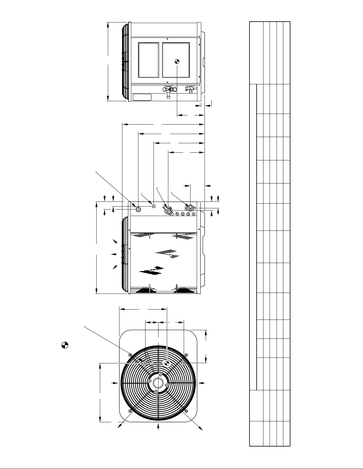
clearance to service end of unit, 48 in. above unit, 6 in. on one side, 12 in. on remaining side,
and 24 in. between units for proper airflow.
Minimum outdoor operating ambient in cooling mode is 55°F (unless low-ambient control is used) max 125°F.2.
Series designation is the 14th position of the unit model number.3.
Center of gravity .4.
1. Allow 30 in.
AIR IN
L
NOTES:
K
D
E
L
C
"
/16
3
8
AIR IN
ABCD E F GHKLMN
SERIES
AIR DISCHARGE
AIR IN
—2—
AIR DISCHARGE
SIZE
UNIT
024 A 39-13/16 30 33 5-1/16 9-11/16 27-15/16 34-3/8 5/8 TBD TBD TBD 2-15/16 26 X 32
030 A 39-13/16 30 33 5-1/16 9-11/16 27-15/16 34-3/8 3/4 TBD TBD TBD 2-15/16 26 X 32
036 A 39-13/16 30 33 5-1/16 9-11/16 27-15/16 34-3/8 3/4 TBD TBD TBD 2-15/16 26 X 32
042 A 39-13/16 30 33 5-1/16 9-11/16 27-15/16 34-3/8 7/8 TBD TBD TBD 2-15/16 26 X 32
TBD—To Be Determined
Page 3
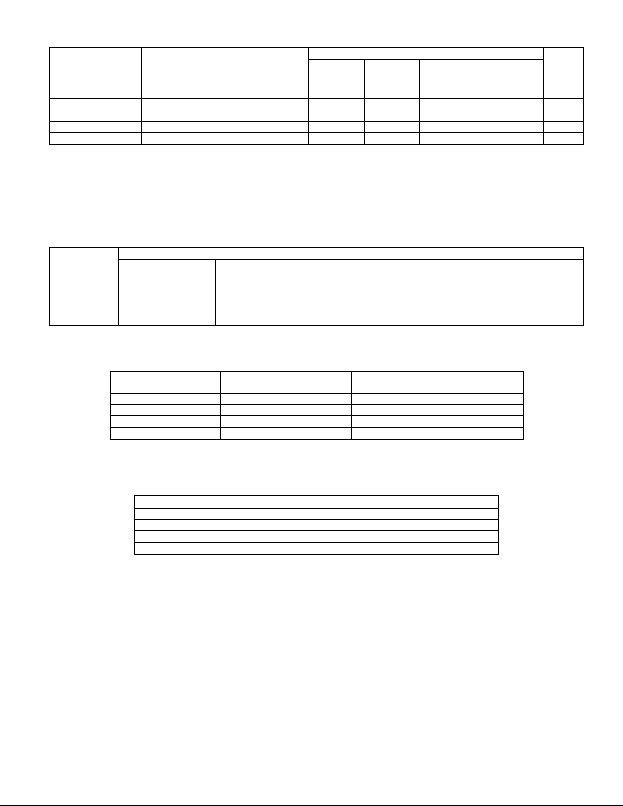
TESTED COMBINATION RATINGS*
SEER
UNIT SIZE-SERIES
INDOOR
MODEL
TOTAL
CAPACITY
BTUH
Factory-
Supplied
Enhance-
ment
Standard
Rating
Bryant Gas
Furnace or
Accessory
TDR†
Accessory
TXV‡
EER
024-A CJ5A/CK5A/CK5BA036 26,600 TXV — 14.00 — 12.00
030-A CJ5A/CK5A/CK5BA042 30,500 TXV — 14.10 — 12.00
036-A CJ5A/CK5A/CK5BA048 36,500 TXV — 14.10 — 11.90
042-A CJ5A/CK5A/CK5BA060 42,000 TXV — 14.00 — 11.90
* Outdoor section/indoor section combination tested in accordance with DOE test procedure for electric air conditioners.
† In most cases, only 1 method should be used to achieve TDR function. Using more than 1 method in a system may cause degradation in performance. Use either the
accessory Time-Delay Relay KAATD0101TDR or a furnace equipped with TDR. All Bryant furnaces are equipped with TDR except for the 394HAD.
‡ Based on computer simulation. TXV must be R-410A compatible and hard shutoff type.
EER—Energy Efficiency Ratio
SEER—Seasonal Energy Efficiency Ratio
TDR—Time-Delay Relay
TXV—Thermostatic Expansion Valve
NOTES: 1. Ratings are net values reflecting the effects of circulating fan heat. Supplemental electric heat is not included.
2. Determine actual CFM values obtainable for your system by referring to fan performance data in fan coil or furnace coil literature.
3. Do not apply with capillary tube coils as performance and reliability are significantly affected.
RECOMMENDED TUBE DIAMETERS
UNIT
SIZE
Tube Length
024 3/8 3/8 5/8 3/4
030 3/8 3/8 3/4 7/8
036 3/8 3/8 3/4 7/8
042 3/8 3/8 7/8 1-1/8
* Tube diameters are for lengths up to 50 ft. For tubing lengths greater than 50 ft, consult the Application Guideline and Service Manual for Residential Split-System Air
Conditioners and Heat Pumps Using R-410A Refrigerant.
NOTE: Refrigerant tubes and indoor coils must be evacuated to 500 microns to minimize contamination and moisture in the system.
LIQUID TUBE DIAMETER (IN.) VAPOR TUBE DIAMETER (IN.)
0to50Ft
Long-Line Applications*
0to50Ft
Tube Length
Long-Line Applications*
(Maximum Diameter)
METERING DEVICE
UNIT SIZE INDOOR TXV*
024-A KSATX0201HSZ TBD
030-A KSATX0201HSZ TBD
036-A KSATX0301HSZ TBD
042-A KSATX0301HSZ TBD
* TXV must be installed when indoor coil is not equipped with an R-410A approved TXV. TXV listed is for any approved coil
combination. All TXVs are R-410A specific hard shutoff.
TBD—To Be Determined
REQUIRED SUBCOOLING
(°F)
SOUND RATING (DBA)
UNIT SIZE-SERIES SOUND RATING
024-A 70
030-A 72
036-A 74
042-A 74
—3—
Page 4

SPECIFICATIONS
UNIT SIZE-SERIES 024-A 030-A 036-A 042-A
Operating Weight (Lb) 291 291 291 291
ELECTRICAL
Unit Volts—Hertz—Phase 208/230—60—1
Operating Voltage Range* 187–253
Compressor— Rated Load Amps 13.5 14.7 15.4 18.6
Locked Rotor Amps 61.0 72.5 83.0 105.0
Condenser Fan Motor—Full Load Amps 0.75 0.75 1.10 1.10
Minimum Unit Ampacity for Wire Sizing TBD TBD TBD TBD
Minimum Wire Size (60°C Copper) (AWG)† TBD TBD TBD TBD
Minimum Wire Size (75°C Copper) (AWG)† TBD TBD TBD TBD
Maximum Wire Length (60°C) (Ft)‡ TBD TBD TBD TBD
Maximum Wire Length (75°C) (Ft)‡ TBD TBD TBD TBD
Maximum Branch Circuit Fuse Size** TBD TBD TBD TBD
COMPRESSOR AND REFRIGERANT
Compressor— Manufacturer Copeland
Type Scroll
Refrigerant— Type R-410A
Amount (Lb)†† 9.88 10.25 10.25 10.50
OUTDOOR COIL & FAN
Coil Face Area (Sq Ft) 18.25 18.25 18.25 18.25
Fins per In.—Rows—Circuits 20—2—4 20—2—4 20—2—4 20—2—4
Fan Motor HP and RPM 1/8 and 825 1/8 and 825 1/5 and 825 1/5 and 825
Rated Airflow (CFM) 2400 2400 2800 2800
OPTIONAL EQUIPMENT
Support Feet—4 In. (4) KSASF0101AAA
Coastal Filter KAACF0201MED
Time-Delay Relay KAATD0101TDR
Cycle Protector—5-Minute Time Delay KSACY0101AAA
Start Assist—Capacitor/Relay Type KSAHS1501AAA
TXV (Hard Shutoff) KSATX0201HSZ KSATX0301HSZ
Filter Drier (Suction Line) KH45LG140 (RCD) KH45LG141 (RCD)
Evaporator Freeze Thermostat‡‡ KAAFT0101AAA
Liquid-Line Solenoid Valve (LSV) KAALS0201LLS
Winter Start Control KAAWS0101AAA
Low-Ambient Pressure Switch KSALA0301410
Low-Ambient Controller P251-0083 (RCD)
MotorMaster® Control*** 32LT660004 (RCD)
Ball Bearing Fan Motor HC38GE230
Thermostat—Auto Changeover, Non-Programmable,
°F/°C, 1-Stage Heat, 1-Stage Cool
Thermostat—Auto Changeover, 7-Day Programmable,
°F/°C, 1-Stage Heat, 1-Stage Cool
Thermidistat™ Control—Programmable Thermostat
with Humidity Control
Thermostat—Manual Changeover, Non-Programmable,
°F, 1-Stage Heat, 1-Stage Cool
Outdoor Air Temperature Sensor TSTATXXSEN01
Backplate for Non-Programmable Thermostat TSTATXXNBP01
Backplate for Programmable Thermostat TSTATXXPBP01
Thermostat Conversion Kit (4 to 5 Wire)—10 Pack TSTATXXCNV10
* Permissible limits of the voltage range at which unit will operate satisfactorily. Operation outside these limits may result in unit failure.
† If other than uncoated (non-plated), 60° or 75°C(140° or 167°F) insulation, copper wire(solid wire for 10 AWG andsmaller, stranded wire for largerthan 10 AWG) is used,
consult applicable tables of the NEC (ANSI/NFPA 70).
If wire isapplied at ambient greater than 30°C (86°F), consult Table310-16 of the NEC (ANSI/NFPA 70). The ampacity ofnonmetallic-sheathed cable (NM), trade name
ROMEX, shall be that of 60°C (140°F) conductors, per the NEC (ANSI/NFPA 70) Article 336-30.
‡ Length shown is as measured 1 way along the wire path between the unit and the service panel for a voltage drop not to exceed 2 percent.
** Time-delay fuse or circuit breaker.
†† The factory refrigerant charge is for 15 ft of interconnecting tubing. For tubing lengths other 15 ft, refer to the Long-Line Application Guideline and Service Manual for
Residential Split-System Air Conditioners and Heat Pumps using R-410A.
‡‡ Use with low-ambient pressure switch.
*** Fan motor with ball bearings required.
TBD—To Be Determined
NOTE: Copper wire must be used from service disconnect to unit. All motors/compressors contain internal overload protection.
TSTATBHNAC01-A
TSTATBHPAC01-A
TSTATBHPRH01-A
HH07AT212
—4—
Page 5

ACCESSORY USAGE GUIDELINE
REQUIRED FOR
ACCESSORY
LOW-AMBIENT
APPLICATIONS
(BELOW 55°F)
Crankcase Heater Yes Yes Yes No
Evaporator Freeze Thermostat Yes No No No
Winter Start Control Yes‡ No No No
Accumulator No No Yes No
Compressor Start Assist
Capacitor and Relay
Yes Yes Yes No
Low-Ambient Controller,
MotorMaster® Control,
or
Yes No No No
Low-Ambient Pressure Switch
Wind Baffle See Low-Ambient Instructions No No No
Coastal Filter No No No Yes
Support Feet Recommended No No Recommended
Liquid-Line Solenoid Valve
or
No
Hard Shutoff TXV
Ball Bearing Fan Motor Yes** No No No
* For tubing line sets between 50 and 175 ft, refer to the Application Guideline and Service Manual for Residential Split-System Air Conditioners and Heat Pumps using
R-410A Refrigerant.
† For buried line applications, refer to Residential Split System Buried-Line Application Guideline.
‡ Only when low-pressure switch is used.
** Required for Low-Ambient Controller (full modulation feature) and MotorMaster® Control only.
REQUIRED FOR
LONG-LINE
APPLICATIONS*
(OVER 50 FT)
See Long-Line
Application
Guideline
REQUIRED FOR
BURIED LINE
APPLICATIONS†
(OVER 3 FT)
Yes No
REQUIRED FOR
SEA COAST
APPLICATIONS
(WITHIN 2 MILES)
—5—
Page 6

R-410A—QUICK REFERENCE GUIDE
• R-410A refrigerant operates at 50-70 percent higher pressures than R-22. Be sure that servicing equipment and replacement
components are designed to operate with R-410A.
• R-410A refrigerant cylinders are rose colored.
• R-410A refrigerant cylinders have a dip tube which allows liquid to flow out of cylinder in upright position.
• Recovery cylinder service pressure rating must be 400 psig, DOT 4BA400 or DOT BW400.
• R-410A systems should be charged with liquid refrigerant. Use a commercial type metering device in the manifold hose.
• Manifold sets should be 700 psig high side and 180 psig low side with 550 psig low-side retard.
• Use hoses with 700 psig service pressure rating.
• Leak detectors should be designed to detect HFC refrigerant.
• R-410A, as with other HFCs, is only compatible with POE oils.
• Vacuum pumps will not remove moisture from oil.
• Do not use liquid-line filter driers with rated working pressures less than 600 psig.
• Do not install a suction-line filter drier in liquid line.
• POE oils absorb moisture rapidly. Do not expose oil to atmosphere.
• POE oils may cause damage to certain plastics and roofing materials.
• Wrap all filter driers and service valves with wet cloth when brazing.
• A liquid-line filter drier is required on every unit.
• Do not use an R-22 TXV.
• If indoor unit is equipped with an R-22 TXV, it must be changed to an R-410A TXV.
• Never open system to atmosphere while it is under a vacuum.
• When system must be opened for service, break vacuum with dry nitrogen prior to opening to atmosphere.
• Always replace filter drier after opening system for service.
• Do not vent R-410A into the atmosphere.
• Do not use capillary tube coils.
• Observe all warnings, cautions, and bold text.
—6—
Page 7

AIR CONDITIONER
MATCHED SYSTEM
VENT PERFECT
HUMIDIFIER
FURNACE COIL
HOMEPERFECT
CONTROL CENTER
FURNACE
AIR CLEANER
PLUS
A97092
SYSTEM DESIGN
1. Intended for outdoor installation with free air inlet and outlet. Outdoor fan external static pressure available is less than 0.01-in. wc.
2. Minimum outdoor operating air temperature without low-ambient operation accessory is 55°F (12.8°C).
3. Maximum outdoor operating air temperature is 125°F (51.7°C)
4. For reliable operation, unit should be level in all horizontal planes.
5. Maximum elevation of indoor coil above or below base of outdoor unit is: indoor coil above = 30 ft; indoor coil below = 30 ft. (See items
6 and 7 following.)
6. For interconnecting tubing lengths greater than 50 ft, consult the Residential Split-System Application Guideline and Service Manual for
Air Conditioners and Heat Pumps using R-410A Refrigerant.
7. If ANY refrigerant tubing is buried, provide a minimum 6-in. vertical rise to the valve connections at the unit. Refrigerant tubing lengths
up to 36 in. may be buried without further considerations. For buried refrigerant tubing lengths greater than 36 in., consult the Residential
Split-System Buried-Line Application Guideline.
8. Use only copper wire for electric connection at unit. Aluminum and clad aluminum are not acceptable for the type of connector provided.
9. Mixmatches of indoor coil capacity of more than 2 sizes larger than outdoor unit capacity may result in inadequate indoor comfort.
10. Do not apply capillary tube indoor coils to these units.
11. Factory-supplied filter drier must be installed.
—7—
Page 8

SERVICE TRAINING
Packaged Service Training programs are an excellent way to increase your
knowledge of the equipment discussed in this manual, including:
• Unit Familiarization • Maintenance
• Installation Overview • Operating Sequence
A large selection of product, theory, and skills programs is available, using popular
video-based formats and materials. All include video and/or slides, plus companion
book.
Classroom Service Training plus "hands-on" the products in our labs can mean
increased confidence that really pays dividends in faster troubleshooting, fewer
callbacks. Course descriptions and schedules are in our catalog.
CALL FOR FREE CATALOG 1-800-962-9212
[ ] Packaged Service Training [ ] Classroom Service Training
A94328
© 1997 Bryant Heating & Cooling Systems 7310 W. Morris St. Indianapolis, IN 46231
—8—
Printed in U.S.A. pf556a1 Catalog No. 5255-601
 Loading...