

Bryant 551J*07A/G Series, 551J*08D/K Series, 551J Series, 551J*07D/K Series, 551J*12D/K Series Installation Instructions Manual
...
551J
SINGLE PACKAGE ROOFTOP
COOLING ONLY
SIZES 07, 08, 09, 11 AND 12 WITH PURONR(R--410A) REFRIGERANT
Installation Instructions
NOTE: Read the entire instruction manual before starting
the installation.
TABLE OF CONTENTS
SAFETY CONSIDERATIONS 2....................
Rated Indoor Airflow (cfm) 3.....................
INSTALLATION 8...............................
Jobsite Survey 8................................
Step 1 -- Plan for Unit Location 8..................
Roof Mount 8...............................
Step 2 -- Plan for Sequence of Unit Installation 8......
Curb--Mounted Installation 9...................
Pad--Mounted Installation 9....................
Frame--Mounted Installation 9..................
Step 3 -- Inspect Unit 9...........................
Step 4 -- Provide Unit Support 9...................
Roof Curb Mount 9..........................
Slab Mount (Horizontal Units Only) 9...........
Alternate Unit Support
(In Lieu of Curb or Slab Mount) 11.............
Step 5 -- Field Fabricate Ductwork 11...............
For Units with Accessory Electric Heaters 11.....
Step 6 -- Rig and Place Unit 11....................
Positioning on Curb 12.......................
Step 7 -- Convert to Horizontal and Connect
Ductwork 12...........................
Step 8 -- Install Outside Air Hood 13...............
Economizer and Two Pos ition Damper Hood
Package Removal and Setup — Factory Option 13..
Economizer Hood and Two--Position Hood 13.....
Step 9 -- Install External Condensate Trap and Line 14.
Step 10 -- Make Electrical Connections 14...........
Field Power Supply 14........................
Units With Factory--Installed
Non--Fused Disconnect 15.....................
Units Without Factory--Installed
Non--Fused Disconnect 16.....................
All Units 16................................
Convenience Outlets 17.......................
Factory Option Thru--Base Connections 18.......
Units Without Thru--Base Connections 18........
Field Control Wiring 18.......................
Thermostat 18...............................
Central Terminal Board 19....................
Unit Without Thru--Base Connection Kit 19.......
Heat Anticipator Settings 19...................
Electric Heaters 19............................
Single Point Boxes and Supplementary Fuses 20...
Single Point Boxes Without Fuses 20............
Low--Voltage Control Connections 21............
Low Ambient Control (Factory Option) 21.........
Variable Frequency Drive (VFD) 2--Speed
Indoor Fan Motor System (Factory--Installed) 21.....
Perfect Humidityt System Control Connections 21..
Perfect Humidity System -- Space RH Contr oller 21..
EconoMi$er
Product Description 23........................
System Components 23.......................
Specifications 23..............................
W7220 Economizer Module 23.................
Electrical 23................................
Inputs 23...................................
Outputs 24.................................
Environmental 24............................
Economizer Module Wiring Details 24...........
S--Bus Sensor Wiring 24......................
CO
Interface Overview 25..........................
User Interface 25............................
Keypad 25.................................
Menu Structure 26.............................
Setup and Configuration 26.....................
Time-- out and Screensaver 26..................
Sequence of Operation 32.......................
Enthalpy Settings 35...........................
Two--Speed Fan Operation 35....................
Checkout 36.................................
Power Up 36................................
Initial Menu Display 36.......................
Power Loss (Outage or Brownout) 37............
Status 37...................................
R
X (Factory--Installed Option) 23......
Sensor Wiring 25........................
2
Checkout Tests 37...........................
Troubleshooting 37............................
Alarms 37..................................
RTU Open Controller System 38.................
Supply Air Temperature (SAT) Sensor 41.........
Outdoor Air Temperature (OAT) Sensor 41.......
EconoMi$er
Field Connections 42..........................
Space Temperature (SPT) Sensors 42............
Indoor Air Quality (CO
Outdoor Air Quality Sensor 43.................
Space Humidity Sensor or Humidistat 44.........
Smoke Detector/Fire Shutdown (FSD) 45.........
Connecting Discrete Inputs 45..................
Communication Wiring -- Protocols 46............
General 46.................................
Local Access 47.............................
RTU Open Controller Troubleshooting 47........
Outdoor Air Enthalpy Control 48.................
Differential Enthalpy Control 48................
Return Air Enthalpy Sensor 48.................
Smoke Detectors 49...........................
Step 11 -- Adjust Factory--Installed Options 50........
Step 12 -- Install Accessories 50...................
Step 13 -- Check Belt Tension 51...................
START--UP CHECKLIST 55.......................
R
242...........................
)Sensor 43.............
2
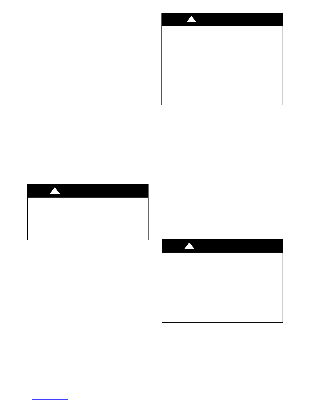
Understand the signal words DANGER, WARNING,
CAUTION, and NOTE. These words are used with the
safety--alert symbol. DANGER identifies the most serious
hazards which will result in severe personal injury or
death. WARNING signifies hazards which could result in
personal injury or death. CAUTION is used to identify
unsafe practices, which may result in minor personal
injury or product and property damage. NOTE is used to
highlight suggestions which will result in enhanced
installation, reliability, or operation.
!
WARNING
ELECTRICAL SHOCK HAZARD
Failure to follow this warning could cause personal
injury or death.
Before performing service or maintenance operations
on unit, turn off main power switch to unit and install
lock(s) and lockout tag(s). Ensure electrical service t o
rooftop unit agrees with voltage and amperage listed
on the unit rating plate. Unit may have more than one
power switch.
!
WARNING
UNIT OPERATION AND SAFETY HAZARD
Failure to follow this warning could cause personal
injury, death and/or equipment damage.
Puronr (R--410A) refrigerant systems operate a t
higher pressures than standard R--22 systems. Do not
use R--22 service equipment or components on Puron
refrigerant equipment.
SAFETY CONSIDERATIONS
Improper installation, adjustment, alteration, service,
maintenance, or use can cause explosion, fire, electrical
shock or other conditions which may cause personal
injury or property damage. Consult a qualified installer,
service agency, or your distributor or branch for
information or assistance. The qualified installer or
agency must use factory--authorized kits or accessories
when modifying this product. Refer to the individual
instructions packaged with the kits or accessories when
installing.
Follow all safety codes. Wear safety glasses and work
gloves. Use quenching cloths for brazing operations and
have a fire extinguisher available. Read these instructions
thoroughly and follow all warnings or cautions attached to
the unit. Consult local building codes and appropriate
national electrical codes (in USA, ANSI/NFPA 70,
National Electrical Code (NEC); in Cana da, CSA C22.1)
for special requirements.
It is important to recognize safety information. This is the
safety--alert symbol
unit and in instructions or manuals, be alert to the
potential for personal injury.
. When you see this symbol on the
!
WARNING
PERSONAL INJURY AND ENVIRONMENTAL
HAZARD
Failure to follow this warning could cause personal
injury or death.
Relieve pressure and recover all refrigerant before
system repair or final unit disposal.
Ware safety glasses and gloves when handling
refrigerants. Keep torches and other ignition sources
away from refrigerants and oils.
!
CUT HAZARD
Failure to follow this caution may result in personal
injury.
Sheet metal parts may have sharp edges or burrs. Use
care and wear appropriate protective clothing, safety
glasses and gloves when handling parts and servicing
air--conditioning equipment.
CAUTION
2
Rated Indoor Airflow (cfm)
The table to the right lists the rated indoor airflow used
for the AHRI efficiency rating for the units covered in thi s
document.
Model Number Full Load Airflow (cfm)
551J*07A/G 2400
551J*07D/K 2400
551J*08D/K 3000
551J*09D/K 3000
551J*11D/K 3000
551J*12D/K 3000
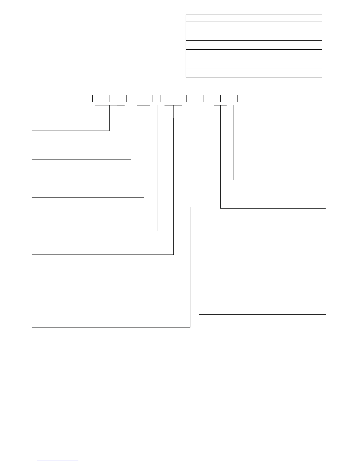
1234567891011 12
551JE12D000A3A0AA
Model
551J = Cooling RTU with optional
High Efficient Electric Heat
Voltage
E = 460-3-60
P = 208/230-3-60
T = 575-3-60
Cooling Tons
07 - 6 ton
08 - 7.5 ton
09 - 8.5 ton
11 - 10 ton (12.0 EER)
12 - 10 ton (11.7 EER)
Refrigerant System/Gas Heat Options
A = Standard One-Stage Cooling Models
D = Two Stage Cooling Models
G = Standard One Stage Cooling Models and Perfect Humidity
K = Two Stage Cooling Models and Perfect Humidity
Heat Level
(Field-installed electric heaters available)
000 = No Heat
Coil Options (Outdoor – Indoor – Hail Guard)
A = Al/Cu – Al/Cu
B = Precoat Al/Cu – Al/Cu
C = E-coat Al/Cu – Al/Cu
D = E-coat Al/Cu – E-Coat Al/Cu
E = Cu/Cu – Al/Cu
F = Cu/Cu – Cu/Cu
M = Al/Cu – Al/Cu – Louvered Hail Guards
N = Precoat Al/Cu – Al/Cu – Louvered Hail Guards
P = E-coat Al/Cu – Al/Cu – Louvered Hail Guards
Q = E-coat Al/Cu – E-coat Al/Cu – Louvered Hail Guards
R = Cu/Cu – Al/Cu – Louvered Hail Guards
S = Cu/Cu – Cu/Cu – Louvered Hail Guards
Fig. 1 -- 551J*07--12 Model Number Nomenclature (Example)
13
14 15 16 17
Packaging and 2-Speed Indoor Fan Motor
A = Standard Packaging, electro-mechanical
controls that require W7212 EconoMi$er
B = LTL Packaging, electro-mechanical controls
that require W7212 EconoMi$er IV
C = Standard Packaging, electro-mechanical
controls that require W7220 EconoMi$er X
D = Standard Packaging and 2-speed Indoor Fan
Motor (VFD) Controller
E = LTL Packaging and 2-speed Indoor Fan
Motor (VFD) Controller
F = LTL Packaging, electro-mechanical controls
that require W7220 EconoMi$er X
Factory-Installed Options
0A = None
NOTE: See the 551J 3 to 15 ton Price Pages for a
complete list of factory-installed options.
TM
Outdoor Air Options
A = None
B = Temperature Economizer w/ Barometric Relief
and W7212 Economizer Controller
E = Temperature Economizer w/ Barometric Relief, CO
and W7212 Economizer Controller
H = Enthalpy Economizer w/ Barometric Relief
and W7212 Economizer Controller
L = Enthalpy Economizer w/ Barometric Relief, CO
and W7212 Economizer Controller
Q = Motorized 2 Position Damper w/ Barometric Relief
U = Temperature Ultra Low Leak Economizer
w/ Barometric Relief
W = Enthalpy Ultra Low Leak Economizer w/ Barometric Relief
Indoor Fan Options
1 = Standard Static Option – Belt Drive
2 = Medium Static Option – Belt Drive
3 = High Static Option – Belt Drive
®
IV
2
2
a551J--- 008
3
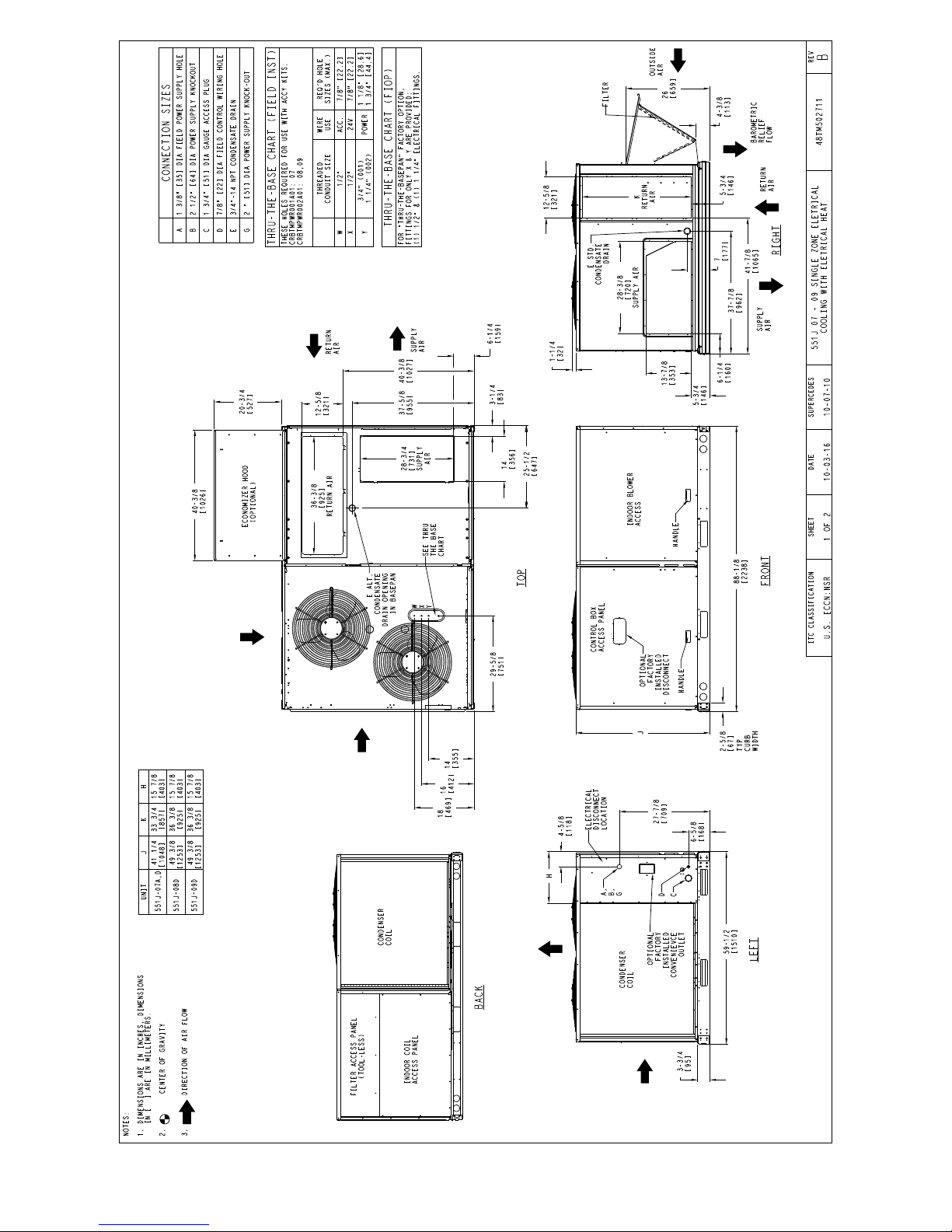
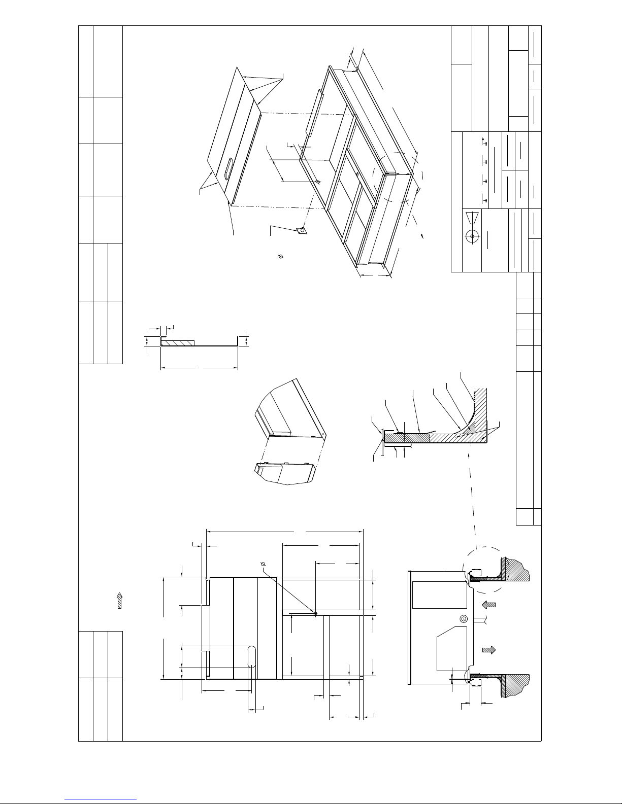
Fig. 2 -- Dimensional Drawing — Sizes 07--09
C160142
4
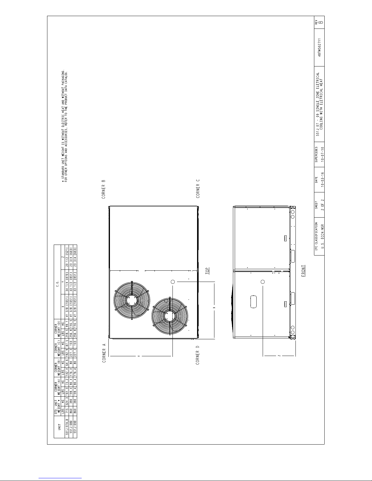
Fig. 2 -- Unit Dimensional Drawing — Sizes 07--09 (cont.)
C160143
5
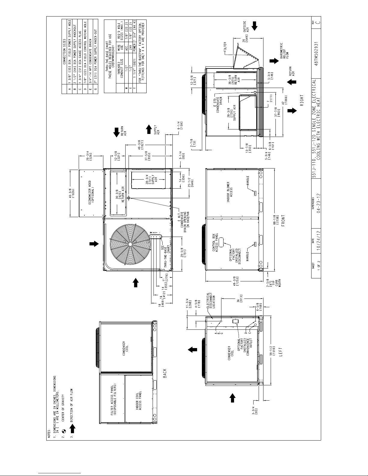
Fig. 3 -- Dimensional Drawing — Sizes 11 and 12
C13302A
6
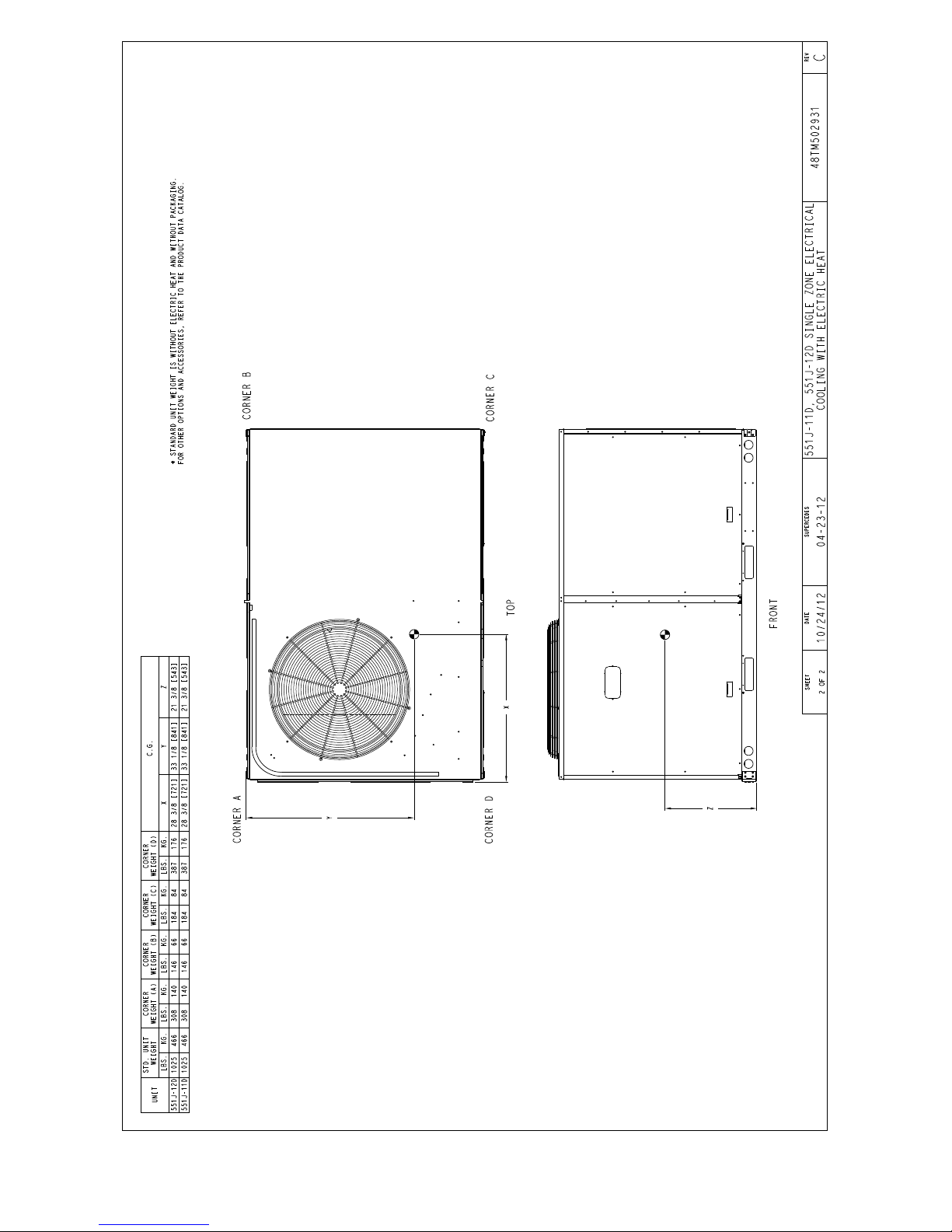
Fig. 3 -- Unit Dimensional Drawing — Sizes 11 and 12 (cont.)
C13303A
7
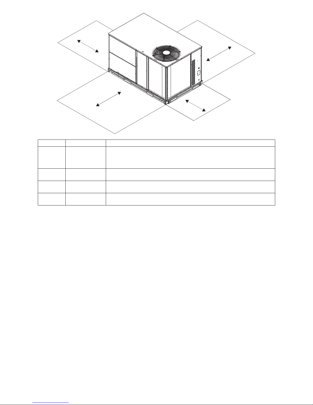
C
D
B
A
LOCATION DIMENSION CONDITION
48--- in. (1219 mm)
A
B
C
D
NOTE: Unit not designed to have overhead obstruction. Contact Application Engineering for guidance on any application
18--- in. (457 mm)
18--- in. (457 mm)
12--- in. (305 mm)
42--- in. (1067 mm)
36--- in. (914 mm)
36--- in. (914 mm)
18--- in. (457 mm)
42--- in. (1067 mm)
36--- in. (914 mm)
planning overhead obstruction or for vertical clearances.
Unit disconnect is mounted on panel
No disconnect, convenience outlet option
Recommended service clearance
Minimum clearance
Surface behind servicer is grounded (e.g., metal, masonry wall)
Surface behind servicer is electrically non ---conductive (e.g., wood, fiberglass)
Side condensate drain is used
Minimum clearance
Surface behind servicer is grounded (e.g., metal, masonry wall, another unit)
Surface behind servicer is electrically non ---conductive (e.g., wood, fiberglass)
C08337
Fig. 4 -- Service Clearance Dimensional Drawing — Sizes 07--12
INSTALLATION
Jobsite Survey
Complete the following checks before installation.
1. Consult local building codes and the NEC (National
Electrical Code) (ANSI/NFPA 70) for special installation requirements.
2. Determine unit location (from project plans) or select
unit location.
3. Check for possible overhead obstructions which may
interfere with unit lifting or rigging.
Step 1 — Plan for Unit Location
Select a location for the unit and its support system (curb
or other) that provides for minimum clearances required
for safety (including clearance to combustible surfaces),
unit performance and service access below, around and
above unit as specified in unit drawings. See Fig. 4.
NOTE: Consider also the effect of adjacent units.
Unit may be installed directly on wood flooring or on Class
A, B, or C roof--covering material when roof curb is used.
Do not install unit in an indoor location. Do not locate air
inlets near exhaust vents or other sources of contaminated
air.
Although unit is weatherproof, avoid locations that perm it
water from higher level runoff and ove rhangs to fall onto
the unit.
Select a unit mounting system that provides adequate
height to allow installation of condensate trap pe r
requirements.RefertoStep9—InstallExternal
Condensate Trap and Line – for required trap dimensions.
Roof Mount —
Check building codes for weight distribution
requirements. Unit operating weight is shown in Table 1.
Step 2 — Plan for Sequence of Unit Installation
The support method used for this unit will dictate different
sequences for the steps of unit installation. For exa mple,
on curb--mounted units, some accessories must be
installed on the unit before the unit is placed on the curb.
Review the following for recommended sequences for
installation steps.
8
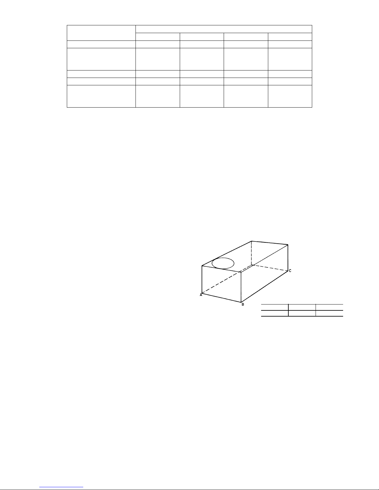
Table 1 – Operating Weights
551J
Base Unit 715 (324) 860 (390) 860 (390) 1025 (466)
Economizer
Vertical 75 (34) 75 (34) 75 (34) 75 (34)
Horizontal 122 (55) 122 (55) 122 (55) 122 (55)
Powered Outlet 35 (16) 35 (16) 35 (16) 35 (16)
Perfect Humidity™ System
Curb
14--- in./356 mm 143 (65) 143 (65) 143 (65) 143 (65)
24--- in./610 mm 245 (111) 245 (111) 245 (111) 245 (111)
1
Not available for size 11 units.
1
07 08 09 11/12
80 (36) 80 (36) 80 (36) 85 (39)
Curb--mounted Installation —
Install curb
Install field--fabricated ductwork inside curb
Install accessory thru --base service connection package
(affects curb and unit) (refer to accessory installation
instructions for details)
Prepare bottom condensate drain connection to suit
planned condensate line routing (refer to Step 9 for
details)
Rig and place unit
Install outdoor air hood
Install condensate line trap and piping
Make electrical connections
Install other accessories
Pad--mounted Installation —
Prepare pad and unit supports
Check and tighten the bottom condensate drain
connection plug
Rig and place unit
Convert unit to side duct connection arrangement
Install field--fabricated ductwork at unit duct openings
Install outdoor air hood
Install condensate line trap and piping
Make electrical connections
Install other accessories
Frame--mounted installation —
Frame--mounted applications generally follow the
sequence for a curb installation. Adapt as required to
suit specific installation plan.
Step 3 — Inspect Unit
Inspect unit for transportation damage. File any claim
with transportation agency.
Confirm before installation of unit that voltage, amperage
and circuit protection requirements listed on unit data
plate agree with power supply provided.
On units with hinged panel option, check to be sure all
latches are snug and in closed position.
Locate the carton containing the outside air hood parts;
see Fig. 10. Do not remove carton until unit has been
rigged and located in final position.
UNITS LB (KG)
Step 4 — Provide Unit Support
Roof Curb Mount —
Accessory roof curb details and dimensions are shown in
Fig. 6. Assemble and install accessory roof curb in
accordance with instru ction s shipped with the curb.
NOTE: The gasketing of t he unit to the roof curb is
critical for a watertight seal. Install gasket supplied with
the roof curb as shown in Fig. 6. Improperly applied
gasket can also result in air leaks and poor unit
performance.
Curb should be level. This is necessary for unit drain to
function properly. Unit leveling tolerances are shown in
Fig. 5. Refer to Accessory Roof Curb Installation
Instructions for additional information as required.
MAXIMUM ALLOWABLE
DIFFERENCE IN. (MM)
A-B
0.5″ (13)
Fig. 5 -- Unit Leveling Tolerances
Install insulation, cant strips, roofing felt, and counter
flashing as shown. Ductwork must be attached to curb and
not to the unit. The accessory thru--the--base power package
must be installed before the unit is set on the roof curb.
If electric and control wiring is to be routed through the
basepan, attach the accessory thru--the--base service
connections to the basepan in accordance with the
accessory installation instructions.
Slab Mount (Horizontal Units Only) —
Provide a level concrete slab that extends a minimum of 6
in. (150 mm) beyond unit cabinet. Install a gravel apron in
front of condenser coil air inlet to prevent grass and
foliage from obstructing airflow.
NOTE: Horizontal units may be installed on a roof curb
if required.
B-C
1.0″ (25)
A-C
1.0″ (25)
a50--- 9658
9
1-3/4"
TYP
[44.5]
C
ACCESSORY CONVENIENCE
OUTLET WIRING CONNECTOR
FITTING
1/2" [12.7] NPT 1/2" [12.7] NPT
CONTROL WIRING
FITTING
POWER WIRING
3/4" [19] NPT 1 1/4" [31.7] NPT
THRU THE CURB
CRBTMPWR004A01 THRU THE BOTTOM
CRBTMPWR002A01
CONNECTOR PKG. ACC. GAS CONNECTION TYPE GAS FITTING
1 3/4"
[44.5]
1.00"
[25.4]
12-1/2" [317.5] WIDE
INSULATED DECK PANELS
INSULATED DECK PANEL
9-15/16" [252.4] WIDE
"A"
1 3/4"
[44.4]
SEE NOTE #2
2-3/8"
[61]
20-3/4"
[513]
INSIDE
GAS SERVICE PLATE
THRU THE CURB
DRILL HOLE
2" [50.8] @
ASSEMBLY (IF
REQUIRED)
(SEE NOTE #8)
SECTION THRU SIDE
RETURN AIR
SUPPLY AIR
UNIT
[1987.5]
6' 6-1/4"
4' 2"
[1270.0]
"A"
NAIL (FIELD SUPPLIED)
TYPICAL (4) SIDES
7/16"
CERTIFIED DRAWING
SEE VIEW "B"
ROOFING FELT
(FIELD SUPPLIED)
COUNTER FLASHING
(FIELD SUPPLIED)
[11]
CURB ASY, ROOF
THIS DOCUMENT AND THE INFORMATION CONTAINED THEREIN
IS PROPRIETARY TO CARRIER CORPORATION AND SHALL NOT
BE USED OR DISCLOSED TO OTHERS, IN WHOLE OR IN PART,
WITHOUT THE WRITTEN AUTHORIZATION OF CARRIER CORPORATION.
1029120
TOLERANCES ON:
AUTHORIZATION NUMBER TITLE
DIMENSIONS ARE IN INCHES
----
UNLESS OTHERWISE SPECIFIED
1 DEC 2 DEC 3 DEC ANG
PRODUCTION
---
MATERIAL
DRAWING RELEASE LEVEL:
THIRD ANGLE
PROJECTION
ROOFING MATERIAL
(FIELD SUPPLIED)
CANT STRIP
(FIELD SUPPLIED)
RIGID INSULATION
SHEET 5 OF 5
50HJ405012
SIZE DRAWING NUMBER REV
D
-
-
-
DRAFTER CHECKER
ENGINEERING MANUFACTURING
MMC 12/16/09 - -
-
-
T-005, Y-002
WEIGHT:
- PURCH - N/A -
ENGINEERING REQUIREMENTS
SURFACE FINISH MFG/PURCH MODEL (INTERNAL USE ONLY) NEXT DRAWING SCALE DISTRIBUTION
ECN NO.APP'DCHK'DBYDATEREVISION RECORDREV
1067898--MMC4/22/13
(FIELD SUPPLIED)
2 1/4"
[57.2]
14 3/4"
[374.7]
NOTES:
1. ROOFCURB ACCESSORY IS SHIPPED DISASSEMBLED.
2. INSULATED PANELS: 25.4 [1"] THK. POLYURETHANE FOAM, 44.5 [1-3/4] # DENSITY.
3. DIMENSIONS IN [ ] ARE IN MILLIMETERS.
4. ROOFCURB: 18 GAGE STEEL.
5. ATTACH DUCTWORK TO CURB. (FLANGES OF DUCT REST ON CURB).
6. SERVICE CLEARANCE 4 FEET ON EACH SIDE.
7. DIRECTION OF AIR FLOW.
8. CONNECTOR PACKAGE CRBTMPWR002A01 IS FOR THRU-THE-CURB GAS TYPE
PACKAGE CRBTMPWR004A01 IS FOR THRU-THE-BOTTOM TYPE GAS CONNECTIONS.
53 1/2"
[1358.9]
11.42"
[290.0]
A
14"
24"
[356]
[610]
26"
[660.4]
6 3/64"
ROOF CURB
ACCESSORY #
CRRFCURB003A01
CRRFCURB004A01
[153.5]
1 3/4"
[44.4]
4 3/16"
[106.0]
81 3/4"
[827.1]
32 9/16"
[2076.3]
3"
40 3/16"
[76.2]
[1020.8]
VIEW "B"
CORNER DETAIL
[585.8]
23 1/16"
OPENING
RETURN AIR
OPENING
SUPPLY AIR
1 3/4"
[44.5]
[401.6]
15 13/16"
DUCT
GASKET
(FIELD SUPPLIED)
(SUPPLIED WITH CURB)
15 15/32
[392.9]
[800.9]
31 17/32"
1 3/4"
[44.5]
6' 61/4" WAS 6' 7 1/6", 4'2' WAS 4' 2 13/16";
18 GA WAS 16 GA.; 15 13/16" WAS 15 15/16"; NAIL
FIELD SUPPLIED WAS WITH CURB
C
SUPPLY AIR RETURN AIR
1/4"
[7.0]
[115.5]
4 9/16"
C13311
Fig. 6 -- Roof Curb Details — Sizes 07--12
10
Alternate Unit Support
(InLieuofCurborSlabMount)—
!
WARNING
A non--combustible sleeper rail can be used in the unit curb
support area. If sleeper rails cannot be used, support the long
sides of the unit with a minimum of 3 equally spaced 4--in. x
4--in. (102 mm x 102 mm) pads on each side.
Step 5 — Field Fabricate Ductwork
Cabinet return-air static pressure (a negative condition)
shall not exceed 0.35 in. wg (87 Pa) with economizer or
0.45 in. wg (112 Pa) without economizer.
For vertical ducted applications, secure all ducts to roof curb
and building structu re. Do not connect ductwork to unit.
Fabricate supply ductwork so that the cross sectional
dimensions are equal to or greater than the unit supply
duct opening dimensions for the first 18 in. (458 mm) of
duct length from the unit basepan.
Insulate and weatherproof all external ductwork, joints,
and roof openings with counter flashing and masti c in
accordance with applicable codes.
Ducts passing through unconditioned spaces must be
insulated and covered with a vapor barrier.
If a plenum return is used on a vertical unit, the return
should be ducted through the roof deck to comply with
applicable fire codes.
PERSONAL INJURY HAZARD
Failure to follow this warning could cause personal
injury.
For vertical supply a nd return units, tools or parts
could drop into ductwork and cause an injury. Install
a 90--degree turn in the return ductwork between the
unit and the conditioned space. If a 90--degree elbow
cannot be installed, then a grille of sufficient strength
and density should be installed to prevent objects
from falling i nto the conditioned space. Due to
electric heater, supply duct will require 90--degree
elbow.
Step 6 — Rig and Place Unit
Keep unit upright and do not drop. Spreader bars are not
required if top crating is left on unit. Rollers may be used to
move unit across a roof. Level by using unit frame as a
reference. See Table 1 and Fig. 7 for additional information.
Lifting holes are provided in base rails as shown in Fig. 7.
Refer to rigging instructions on unit.
Rigging materials under unit (cardboard to prevent base
pan damage) must be removed PRIOR to placing the unit
on the roof curb.
!
PROPERTY DAMAGE HAZARD
Failure to follow this caution may result in damage
to roofing materials.
Membrane roofs can be cut by sharp shee t metal
edges. Be careful when placing any sheet metal parts
on such roof.
For Units with Accessory Electric Heaters —
Horizontal applications require a minimum clearance to
combustible surfaces of 1--in. (25 mm) from duct for first
12--in. (305 mm) away from unit. Vertical applications do
not require a minimum clearance.
Minimum clearance is not required around ductwork.
Outlet grilles must not lie directly below unit discharge.
CAUTION
When using the standard side drain connection, ensure the
red plug in the alternate bottom connection is tight. Do
this before setting the unit in place. The red drain pan can
be tightened with a
For further details see Step 9 -- Install External
Condensate Trap and Line on page 14.
Before setting the unit onto the curb, recheck gasketing on
curb.
!
UNIT DAMAGE HAZARD
Failure to follow this caution may result in
equipment damage.
All panels must be in place when rigging. Unit is not
designed for handling by fork truck when panels or
packaging are removed.
If using top crate as spreader bar, once unit is set,
carefully lower wooden crate off building roof top to
ground. Ensure that no people or obstructions are
below prior to lowering the crate.
1
/2--in. square socket drive extension.
CAUTION
11
UNIT
551J*07 1130 514 88.0 2235 43.0 1090 41.5 1055
551J*08 1340 609 88.0 2235 43.0 1090 49.5 1255
551J*09 1340 609 88.0 2235 43.0 1090 49.5 1255
551J*11/12 1580 718 88.0 2235 31.5 775 49.5 1255
NOTES:
1. Dimensions in ( ) are in millimeters.
2. Hook rigging shackles through holes in base rail, as shown in detail “A.” Holes in base rails are centered around the unit center of gravity.
Use wooden top to prevent rigging st rap s from damag ing unit.
MAX WEIGHT
LB KG IN. MM IN. MM IN. MM
A B C
DIMENSIONS
Fig. 7 -- Rigging Details
C06005
PositioningonCurb—
Position unit on roof curb so that the following clearances
1
are maintained:
/4in. (6.4 mm) clearance between the
roof curb and the base rail inside the front and rear, 0.0 in.
clearance between the roof curb and the base rail inside on
the duct end of the unit. This will result in the distance
between the roof curb and the base rail inside on the
5
condenser end of the unit being approximately 3--
/16in.
(84 mm).
Although unit is weatherproof, guard against water from
higher level runoff and overhangs.
!
CAUTION
UNIT DAMAGE HAZARD
Failure to follow this caution may result in
equipment damage.
All panels must be in place when rigging. Unit is not
designed for handling by fork truck.
After unit is in position, remove rigging skids and
shipping materials.
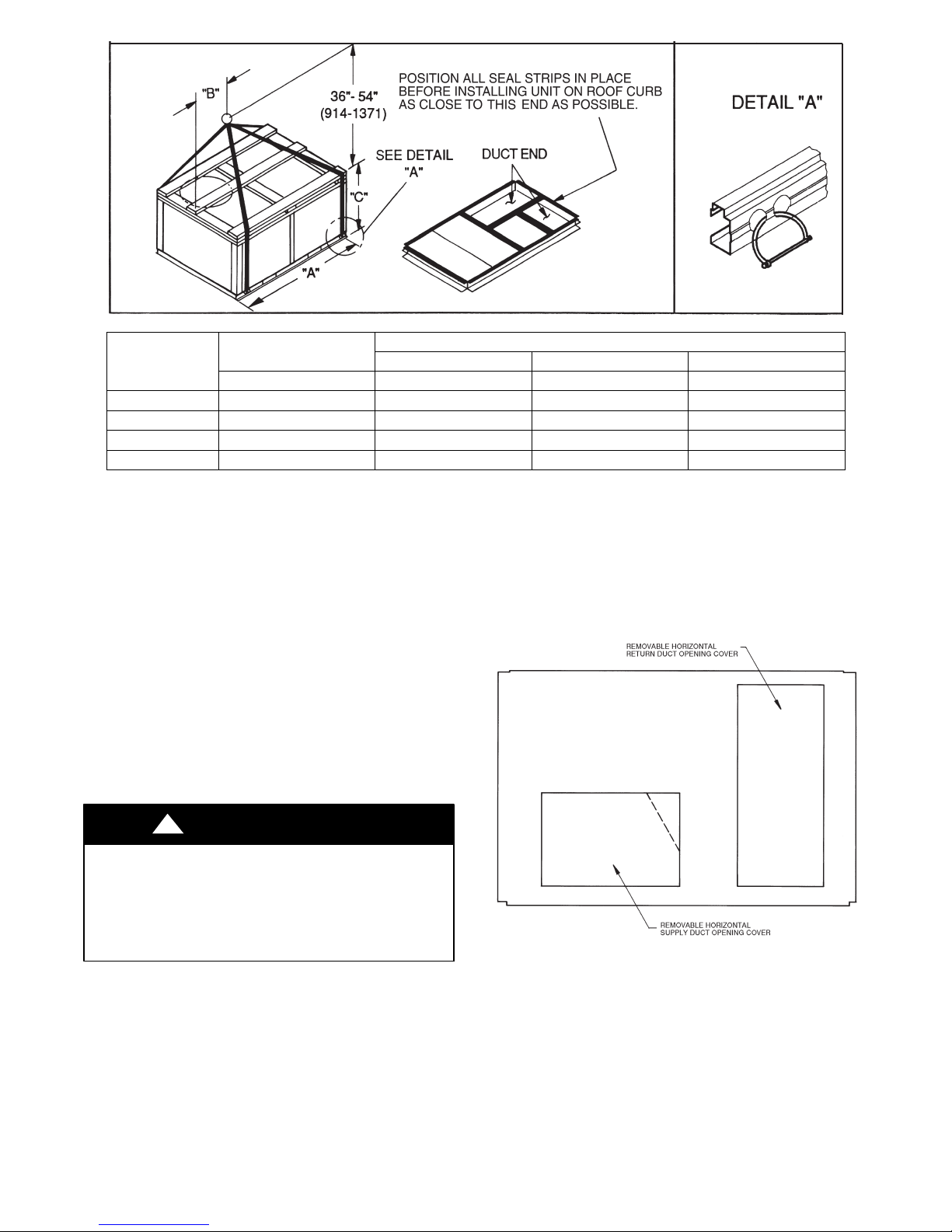
Step 7 — Convert to Horizontal and Connect
Ductwork (when required)
Unit is shipped in the vertical duct configuration. Unit
without factory--installed economizer or return air smoke
detector option may be field--converted to horizontal ducted
configuration. To convert to horizontal configuration,
remove screws from side duct opening covers and remove
covers. Using the same screws, install covers on vertical
duct openings with the insulation--side down. Seals around
duct openings must be tight. See Fig. 8.
C06108
Fig. 8 -- Horizontal Conversion Panels
Field--supplied flanges should be attached to horizontal
duct openings and all ductwork should be secured to the
flanges. Insulate and weatherproof all e xternal ductwork,
joints, and roof or building openings with counter flashing
and mastic in accordance with applicable codes.
Do not cover or obscure visibility to the unit’s informative
data plate when insulating horizont al ductwork.
12
Step 8 — Install Outside Air Hood
Economizer and Two Position Damper Hood
Package Removal and Setup -- Factory Option
1. The hood is shipped in knock--down form and must be
field assembled. The indoor coil access panel is used as
the hood top while the hood sides, divider and filter are
packaged together, attached to a metal support tray using plastic stretch wrap, and shipped in the return air
compartment behind the indoor coil access panel. The
hood assembly’s metal tray is attached to the basepan
and also attached to the damper using two plastic tie-wraps.
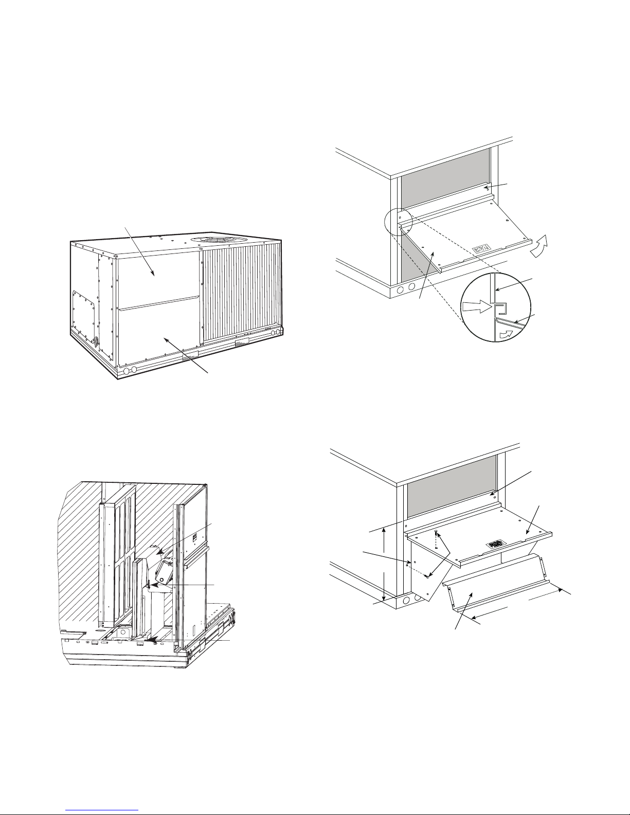
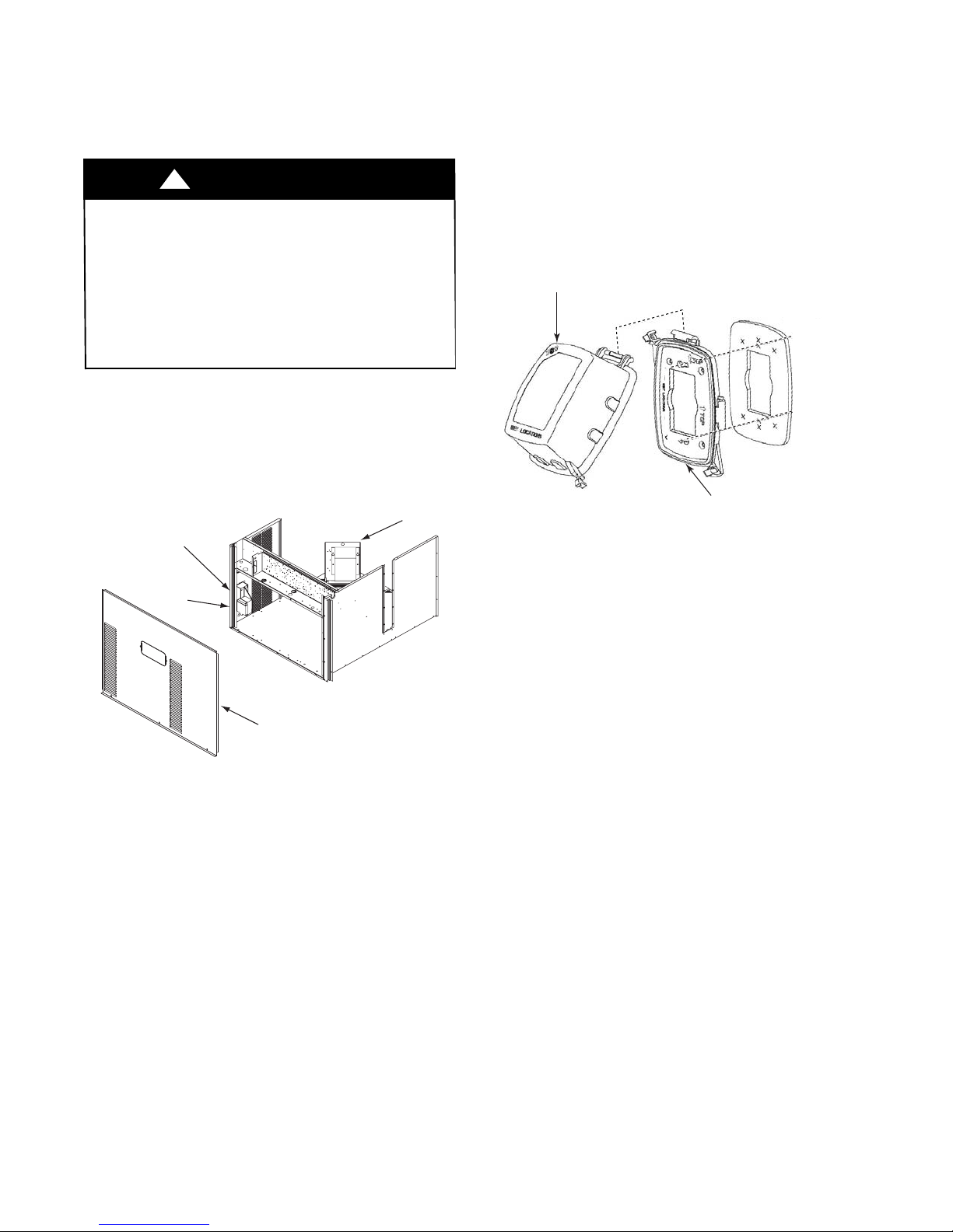
2. To gain access to the hood, remove the filter access
panel. (See Fig. 9.)
FILTER ACCESS PANEL
Economizer Hood and Two--Position Hood —
NOTE: If the power exhaust accessory is to be installed
on the unit, the hood shipped with the unit will not be
used and must be discarded. Save the aluminum filter for
use in the power exhaust hood assembly.
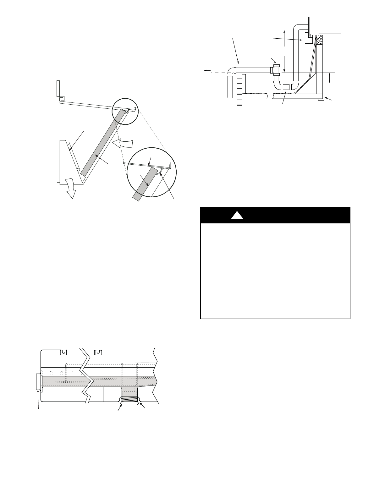
1. The i ndoor coil access panel will be used as the top of
the hood. Remove the screws along the sides and bottom of the indoor coil access panel. See Fig. 11.
TOP
PAN EL
TOP
PAN EL
INDOOR
COIL
ACCESS
PAN EL
INDOOR
COIL
ACCESS
PAN EL
CAULK
HERE
INDOOR COIL ACCESS PANEL
C10146
Fig. 9 -- Typical Access Panel Locations
3. Locate the (2) screws holding the metal tray to the
basepan and remove. Locate and cut the (2) plastic
tie--wraps securing the assembly to the damper. (See
Fig. 10.) Be careful to not damage any wiring or cut
tie--wraps securing any wiring.
Hood Parts
Plastic Tie Wrap
Qty (2)
Screws for Metal Tray
Qty (2)
Fig. 11 -- Indoor Coil Access Panel Relocation
C06025
2. Swing out indoor coil access panel and insert the
hood sides under the panel (hood top). Use the screws
provided to attach the hood sides to the hood top. Use
screws provided to attach the hood sides to the unit.
See Fig. 12.
TOP
PANEL
INDOOR COIL
ACCESS PANEL
LEFT
HOOD
SIDE
19 1/16″
B
(483 mm)
HOOD DIVIDER
SCREW
33 3/8″
(848 mm)
a50--- 9659
Fig. 12 -- Economizer Hood Construction
Fig. 10 -- Economizer and Two--Position Damper
Hood Parts Location
4. Carefully lift the hood assembly (with metal tray)
through the filter access opening and assemble per the
steps outlined in Economizer Hood and Two–Position
Hood.
C08639
3. Remove the shipping tape hol ding the economizer
barometric relief damper in place (economizer only).
4. Insert the hood divider between the hood sides. See
Fig. 12 and 13. Secure hood divider with 2 screws on
each hood side. The hood divider is also used as the
bottom filter rack for the aluminum filter.
13
5. Open the filter clips which are located underneath the
hood top. Insert the aluminum filter into the bottom
filter rack (hood divider). Push the filter into position
past the open filter clips. Close the filter clips to lock
the filter into place. See Fig. 13.
6. Caulk the ends of the joint between the unit top panel
and the hood top.
7. Replace the filter access panel.
DIVIDER
OUTSIDE
AIR
MINIMUM PITCH
1˝ (25 mm) PER
10´ (3 m) OF LINE
TO ROOF
DRAIN
NOTE: Trap should be deep enough to offset maximum unit static
difference. A 4 in. (102 mm) trap is recommended.
BASE RAIL
OPEN
VENT
3˝(76 mm)
MIN
DRAIN PLUG
Fig. 15 -- Condensate Drain Piping Details
SEE NOTE
ROOF
CURB
a50--- 9660
HOOD
CLEANABLE
BAROMETRIC
RELIEF
ALUMINUM
FILTER
FILTER
FILTER
CLIP
C08634
Fig. 13 -- Economizer Filter Installation
Step 9 — Install External Condensate Trap and Line
The unit has one3/4-in. condensate drain connection on
the end of the condensate pan and an alternate connection
on the bottom. See Fig. 14. Unit airflow configuration
does not determine which drai n connection to use. Either
drain connection can be used with vertical or horizontal
applications.
When using the standard side drain connection, ensure the
red plug in the alternate bottom connection is tight. Do this
before setting the unit in place. The red drain pan plug can
1
be tightened with a
/2--in. square socket drive extension.
To use the alternate bottom drain connect ion, remove the
1
red drain plug from the bottom connection (use a
/2-- i n .
square socket drive extension) and install it in the side
drain connection.
All units must have an external trap for condensate
drainage. Install a trap at least 4-in. (102 mm) deep and
protect against freeze-up. If drain line is installed
downstream fr om the external trap, pitch the line away from
the unit at 1-in. per 10 ft (25 mm in 3 m) of run. Do not use
3
a pipe size smaller than the unit connection (
/4-in.).
Step 10 — Make Electrical Connections
!
WARNING
ELECTRICAL SHOCK HAZARD
Failure to follow this warning could result in personal
injury or death.
Unit cabinet must have an uninterrupted, unbroken
electrical ground to minimize the possibility of personal
injury if an electrical fault should occur. This ground
may consist of electrical wire connected to unit ground
lug in control compartment, or conduit approved for
electrical ground when installed in accordance with
NEC; ANSI/NFPA 70, latest edition (in Canada,
Canadian Electrical Code CSA [Canadian Standards
Association ] C22.1), and local electrical codes.
NOTE: Field--supplied wiring shall conform with the
limitations of minimum 63_F(33_C) rise.
Field Power Supply —
CONDENSATE PAN (SIDE VIEW)
STANDARD
SIDE DRAIN
DRAIN
PLUG
(FACTORY-INSTALLED)
Fig. 14 -- Condensate Drain Pan (Side View)
The piping for the condensate drain and external trap can
be completed after the unit is in place. See Fig. 15.
ALTERNATE
BOTTOM DRAIN
C08021
If equipped with optional Powered Convenience Outlet: The
power source leads to the convenience outlet’s transformer
primary are not factory connected. Installer must connect
these leads according to required operation of the
convenience outlet. If an always--energized convenience
outlet operation is desired, connect the source leads to the
line side of the unit--mounted disconnect. (Check with local
codes to ensure this method is acceptable in your area.) If a
de--energize via unit disconnect switch operation of the
convenience outlet is desired, connect the source leads to the
load side of the unit disconnect. On a unit without a
unit--mounted disconnect, connect the source leads to
compressor contactor C and indoor fan contactor IFC
pressure lugs with unit field power leads (see Fig. 16).
14
L3
L2
L1
Ground
(GR)
Units Without Disconnect Option
CIFC
13 11 1 3
Disconnect
per
NEC
L1 L2 L3
208/230-3-60
460-3-60
575-3-60
Ground
(GR)
Equip
GR Lug
Units With Disconnect Option
L3
Optional
Disconnect
L2
L1
Disconnect factory test leads; discard.
Switch
T3
T2
T1
BLU
YEL
BLK
Equip GR Lug
Factory
Wiring
Refer to Fig. 23 for power transformer connections and the
discussion on connecting the convenience outlet on page 17.
Field power wires are connected to the unit at line--side
pressure lugs on compressor contactor C and indoor fan
contactor IFC (see wiring diagram label for control box
component arrangement), at factory--installed option
non--fused disconnect switch. Max wire size is #4 AWG
(copper only) per pole on contactors and #2ga AWG (copper
only) per pole on optional non--fused disconnect. See Fig. 16
and the unit label diagram for field power wiring
connections.
NOTE: TEST LEADS -- Unit may be equipped with short
leads (pigtails) on the field line connection points on
contactor C or optional disconnect switch. These leads are
for factory run--test purposes only; remove and discard
before connecting field power wires to unit connection
points. Make field power connections directly to line
connection pressure lugs only.
!
WARNING
FIRE HAZARD
Failure to follow this warning could result in
personal injury, death, or property damage.
Do not connect aluminum wire between disconnect
switch and 551J unit. Use only copper wire. (See Fig. 17.)
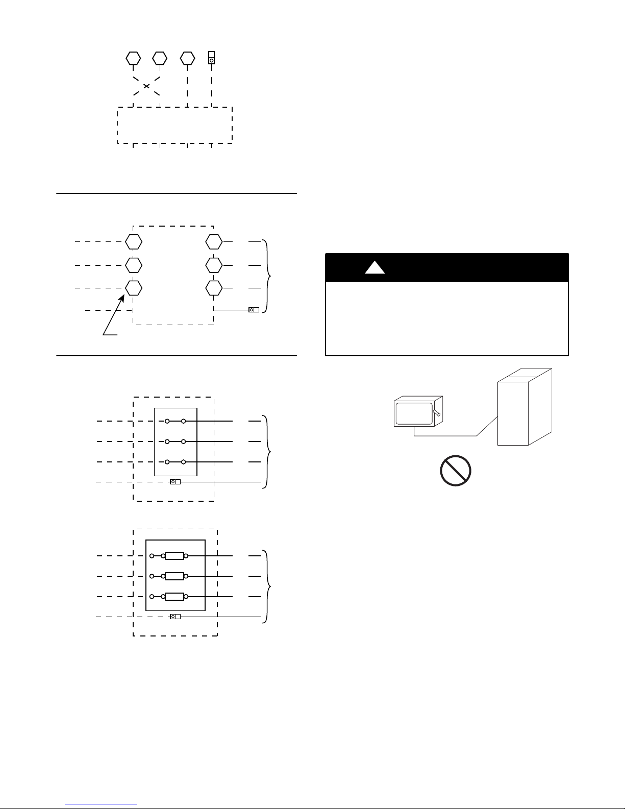
Units With Electric Heat Option with Single Point Box
and Without Disconnect Option
Single Point Box
Ground (GR)
L1
L2
L3
Terminal Block
Equip GR
Lug
BLK
YEL
BLU
— OR —
Single Point Box
L1
L2
L3
Ground (GR)
Fuse/Terminal Block
Fuse
Fuse
Fuse
Equip GR
Lug
BLK
YEL
BLU
Fig. 16 -- Power Wiring Connections
Factory
Wiring
Factory
Wiring
C12763
ELECTRIC
DISCONNECT
SWITCH
COPPER
WIRE ONLY
ALUMINUM
WIRE
A93033
Fig. 17 -- Disconnect Switch and Unit
Units With Factory--Insta lled Non--Fused Disco n n ect —
The factory--install ed option non--fused disconnect (NFD)
switch is located in a weatherproof enclosure located
under the main control box (see Fig. 18). The manual
switch handle and shaft are shipped in the disconnect
enclosure. Assemble the shaft and handle to the switch at
this point. Discard the factory test leads (see Fig. 16).
Connect field power supply conductors to LINE side
terminals when the switch enclosure cover is removed to
attach the handle.
15
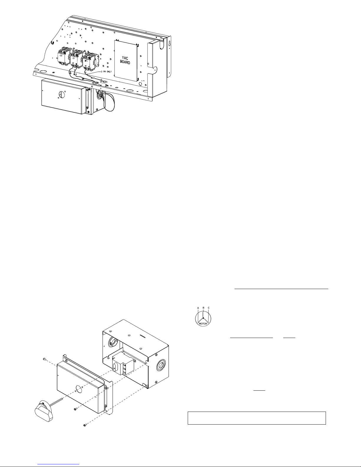
C12278
Fig. 18 -- Location of Non--Fused Disconnect Enclosure
To field install the NFD shaft and handle:
1. Remove the unit front panel (see Fig. 2 or Fig. 3).
2. Remove (3) hex screws on the NFD enclosure -- (2) on
the face of the cover and (1) on the left side cover. See
Fig. 19.
3. Remove the front cover of the NFD enclosure.
4. Make sure the NFD shipped from the factory is at OFF
position (the arrow on the black handle knob is at OFF) .
5. Insert the shaft with the cross pin on the top of the shaft
in the horizontal position.
6. Measure from the tip of the shaft to the top surface of
the black pointer; the measurement should be 3.75 to
3.88 in. (95 to 99 mm).
7. Tighten the locking screw to secure the shaft to the
NFD.
8. Turn the handle to the OFF position with red arrow
pointing at OFF.
9. Install the handle on to the painte d cover horizontally
with the red arrow pointing to the left.
10. Secure the handle to the painted cover with (2) screws
and lock washers supplied.
11. Engaging the shaft into the handle socket, re--install
(3) hex screws on the NFD enclosure.
12. Re--install the unit front panel.
Units Without Factory--Installed
Non--Fused Disconnect —
When installing units, provide a disconnect switch per NEC
(National Electrical Code) of adequate size. Disconnect
sizing data is provided on the unit informative plate. Locate
on unit cabinet or within sight of the unit per national or
local codes. Do not cover unit informative plate if mounting
the disconn ect on the unit cabinet.
All Units —
All field wiring must comply with NEC and all local codes.
Size wire based on MCA (Minimum Circuit Amps) on the
unit informative plate. See Fig. 16 and the unit label
diagram for power wiring connections to the unit power
terminal blocks and equipment ground. Maximum wire size
is #4 ga AWG (copper only) per pole on contactors and
#2ga AWG (copper onl y) per pole on optional non--fused
disconnect.
Provide a ground--fault and short--circuit over--current
protection device (fuse or breaker) per NEC Article 440
(or local codes). Refer to unit informative data plate for
MOCP (Maximum Over--current Protection) device size.
All field wiring must comply with the NEC and local
requirements.
All units except 208/230-v units are factory wired for the
voltage shown on the nameplate. If the 208/230-v unit is
to be connected to a 208-v power supply, the control
transformer must be rewired by moving the black wire
1
with the
connection and moving it to the 208-v
/4-in. female spade connector from the 230--v
1
/4-in. male
terminal on the primary side of the transformer. Refer to
unit label diagram for additional information.
Voltage to compressor terminals during operation must be
within volt age range indicated on unit nameplate. On
3--phase units, voltages between phases must be balanc ed
within 2% and the current within 10%. Use the formula
below to determine the percent of voltage imbalance.
%Voltage
Imbalance
Example: Supply voltage is 230-3-60
= 100 x
max voltage deviation from average voltage
average voltage
AB = 224 v
BC = 231 v
AC = 226 v
Fig. 20 -- Handle and Shaft Assembly for NFD
C12279
Average Voltage =
Determine maximum deviation from average voltage.
(AB) 227 – 224 = 3 v
(BC) 231 – 227 = 4 v
(AC) 227 – 226 = 1 v
Maximum deviation is 4 v.
Determine percent of voltage imbalance.
%VoltageImbalance
This amount of phase im balance is satisfactory as it is below the
maximum allowable 2%.
IMPORTANT: If the supply voltage phase imbalance is more than
2%, contact your local electric utility company immediately.
(224 + 231 + 226)
3
= 100 x
4
227
= 1.76%
681
=
3
=227
Operation on improper line voltage or excessive phase
imbalance constitutes abuse and may cause damage to
16
electrical components. Such operation would invalidate
any applicable Bryant warranty.
NOTE: Check all factory and field electrical connections
for tightness.
Convenience Outlets —
!
WARNING
ELECTRICAL OPERATION HAZARD
Failure to follow this warning could result in personal
injury or death.
Units with convenience outlet circ uits may use
multiple disconnects. Check convenience outlet for
power status before opening unit for service. Locate
its disconnect switch, if appropriate, and open it.
Lock--out and tag--out this switch, if necessary.
Tw o types of convenience outlets are offered on 551J models:
Non--powered and unit--powered. Both types provide a
125--volt GFCI (ground--fault circuit--interrupter) duplex
receptacle rated at 15--A behind a hinged waterproof access
cover, located on the end panel of the unit. See Fig. 21.
Pwd-CO
Convenience
Outlet
GFCI
Transformer
Remove the blank cover plate at the convenience outlet ;
discard the blank cover.
Loosen the two screws at the GFCI duplex outlet, until
1
approximately
/2-in. (13 mm) under screw heads are
exposed. Press t he gasket over the screw heads. Slip the
backing plate over the screw heads at the keyhole slots
and align with the gasket; tighten the two screws until
snug (do not over-tighten).
Mount the wea therproof cover to the backing plate as
shown in Fig. 22. Remove two slot fillers in the bottom of
the cover to permit service tool cords to exit the cover.
Check for full closing and latching.
COVER – WHILE-IN-USE
WEATHERPROOF
RECEPTACLE
NOT INCLUDED
BASE PLATE FOR
GFCI RECEPTACLE
C09022
Fig. 22 -- Weatherproof Cover Installation
Pwd-CO
Fuse
Switch
Control Box
Access Panel
C08128
Fig. 21 -- Convenience Outlet Location
Installing Wea therproof C o ver: A weatherproof
while-in-use cover for the factory-installed convenience
outlets is now required by UL standards. This cover cannot
be factory-mounted due its depth; it must be installed at unit
installation. For shipment, the convenience outlet is covered
with a blank cover plate.
The weatherproof cover kit is shipped in the unit’s control
box. The kit i ncludes the hinged cover, a backing plate
and gasket.
DISCONNECT ALL POWER TO UNIT AND
CONVENIENCE OUTLET. LOCK--OUT AND TAG--OUT
ALL POWER.
Non--powered type: This type requires the field
installation of a general--purpose 125--volt 15--A circuit
powered from a source elsewhere in the building. Observe
national and loca l codes when selecting wire size, fuse or
breaker requirements and disconnect switch size and
location. Route 125--v power supply conductors into the
bottom of the utility box containing the duplex receptacle.
Unit--powered type: A unit--mounted transformer is
factory--installed to stepdown the main power supply
voltage to the unit to 115--v at the duplex receptacle. This
option also includes a manual switch with fuse, located in
a utility box and mounted on a bracket behind the
convenience outlet; access is through the unit’s c ontrol
box access panel. See Fig. 21.
The primary leads to the convenience outlet transformer are
not factory--connected. Selection of primary power source is
a customer--option. If local codes permit, the transformer
primary leads can be connected at the line--side terminals on
the unit--mounted non--fused disconnect switch; this will
provide service power to the unit when the unit disconnect
switch is open. Other connection methods will result in the
convenience outlet circuit being de--energized when the unit
disconnect switch is open. See Fig. 23.
17
 Loading...