

Page 1
installation, start-up
and service instructions
SINGLE PACKAGE ROOFTOP
HIGH-EFFICIENCY HEAT PUMP UNITS
IMPORTANT — READ BEFORE INSTALLING
1. Read and become familiar with these installation instructions before installing this unit (Fig. 1).
2. Be sure the installation conforms to all applicable local
and national codes.
3. These instructionscontainimportant information for the
proper maintenance and repair of this equipment.
Retain these instructions for future use.
549B
Sizes 090,120
71⁄2and 10 Tons
Cancels: New II 549B-90-1
7/15/95
CONTENTS
Page
SAFETY CONSIDERATIONS ........................1
INSTALLATION .................................1-16
I. Locate the Unit .............................3
II. Unit Duct Connections ......................3
III. Rig and Place Unit ..........................3
IV. Field Connections ..........................6
PRE-START-UP ................................16,17
START-UP ....................................17-24
I. Compressor Rotation .......................17
II. Heating Section Start-Up and Adjustments
For Units With Accessory Electric Heat .......17
III. Cooling Section Start-Up and Adjustments ....18
IV. Indoor Airflow and Airflow Adjustments .......19
CARE AND MAINTENANCE .......................25
I. Air Filter ..................................25
SERVICE .....................................25-27
I. Cleaning .................................25
II. Lubrication ...............................26
III. Outdoor-Fan Adjustment ....................26
IV. Economizer Adjustment ....................26
V. Refrigerant Charge .........................26
VI. Replacement Parts .........................27
TROUBLESHOOTING ...........................28-30
START-UP CHECKLIST ..........................CL-1
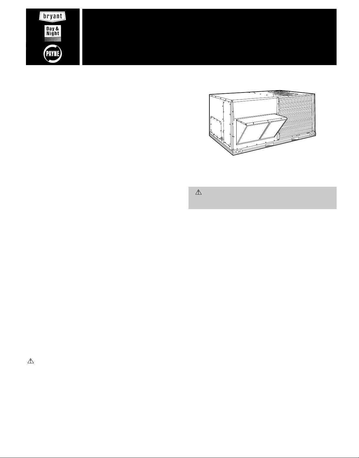
Fig.1—Typical Unit
WARNING:
nance operations on unit, turn off main power switch
to unit. Electrical shock could cause personal injury.
1. The power supply (volts, hertz, and phase) must correspond to that specified on unit rating plate.
2. The electrical supply provided by the utility must be sufficient to handle unit load.
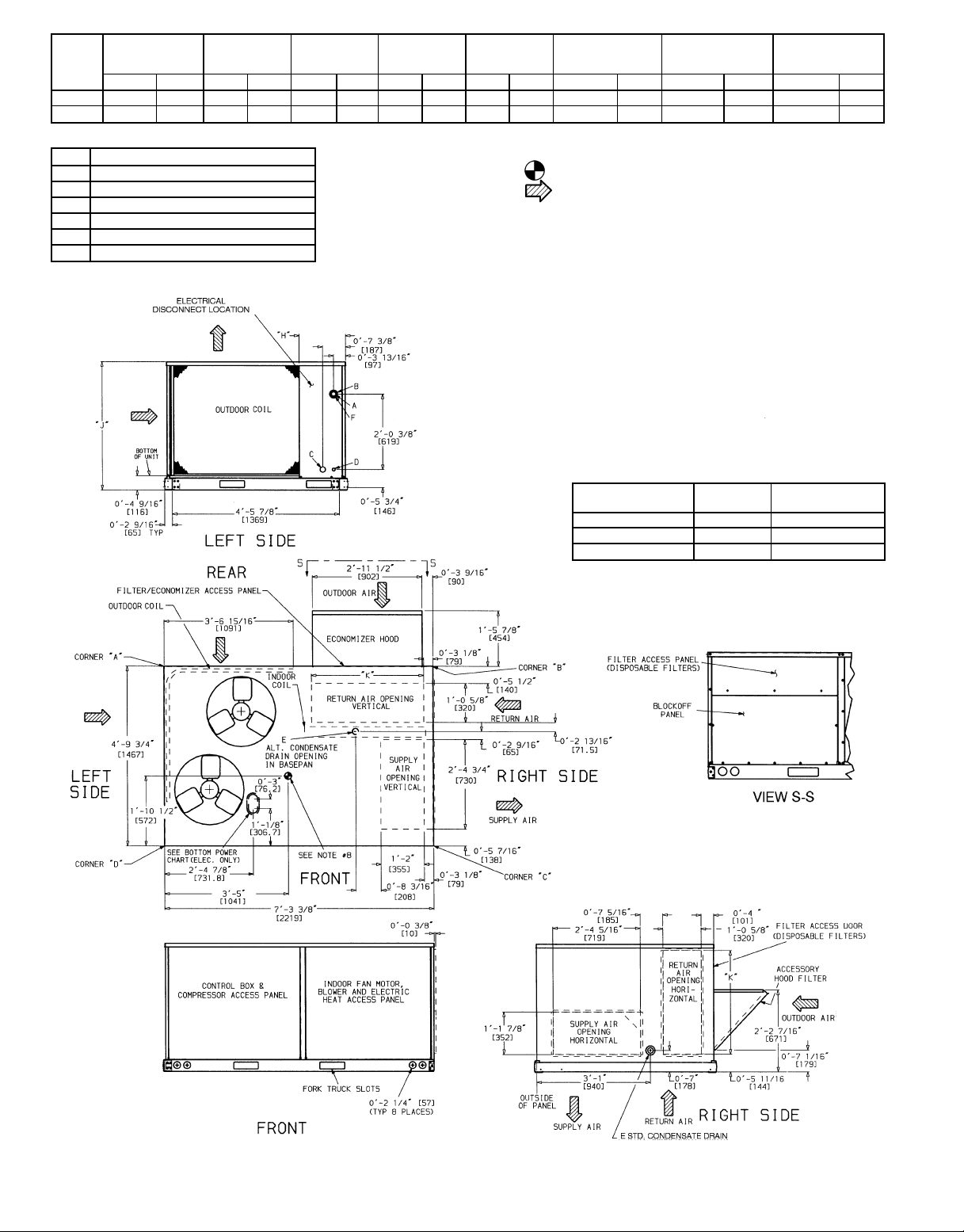
3. Refer to Locate the Unit section on page 3 and Fig. 2 for
locations of electrical inlets, condensate drain, duct connections, and required clearances before setting unit in
place.
4. This installation must conform with local building codes
and with NEC (National Electrical Code) or NFPA
(National Fire Protection Association) 54 TIA-54-1.
Refer to provincial and local plumbing or wastewater codes
and other applicable local codes.
5. Approved for outdoor installation on wood flooring or on
class A, B, or C roof covering materials.
Before performing service or mainte-
SAFETY CONSIDERATIONS
Recognize safety information. This is the safety-alert symbol
( ). When you see this symbol on the unit and in instructions or manuals, be alert to the potential for personal
injury.
Understand the signal words — DANGER, WARNING, and
CAUTION. These words are used with the safety-alert symbol. Danger identifies the most serious hazards which will
result in severe personal injury or death. Warning indicates
a situation that could result in personal injury. Caution is
used to identify unsafe practices which would result in minor
personal injury or product and property damage.
INSTALLATION
Unit is shipped in the vertical airflow configuration (see
Fig. 1). To convert to horizontal discharge, remove side duct
opening covers. Using the same screws, install covers with
insulation-side down (facing outside) on the unit over vertical duct openings. Seals around duct openings must
be tight.
All units can be connected into existing duct systems that are
properly sized and designed to handle an airflow of 300 to
500 cfm per each 12,000 Btuh of rated cooling capacity.
Page 2
UNIT
549B
STANDARD
UNIT
WEIGHT
CORNER
WEIGHT
(A)
CORNER
WEIGHT
(B)
CORNER
WEIGHT
(C)
CORNER
WEIGHT
(D)
Lb Kg Lb Kg Lb Kg Lb Kg Lb Kg ft-in. mm ft-in. mm ft-in. mm
090 870 395 195 90 183 83 237 108 252 114 28-0
120 1000 454 231 105 214 97 269 122 286 130 28-10
NOTES:
CONNECTION SIZES
3
A 1
B 2
C 1
D
E
⁄89 Dia. [35] Field Power Supply Hole
1
⁄29 Dia. [64] Power Supply Knock-Out
3
⁄49 Dia. [44] Charging Port Hole
7
⁄89 Dia. [22] Field Control Wiring Hole
3
⁄49-14 NPT Condensate Drain
F 29 Dia. [51] Power Supply Knock-Out
1. Dimensions in [ ] are in millimeters.
2. Center of Gravity.
3. Direction of airflow.
4. Ductwork to be attached to accessory roof curb only.
5. Minimum clearance (local codes or jurisdiction may prevail):
a. Bottom to combustible surfaces (when not using curb) 0 in., on horizon-
tal discharge units with electric heat, 1 in. clearance to ductwork for 1 ft.
b. Outdoor coil, for proper airflow, 36 in. one side, 12 in. the other. The
side getting the greater clearance is optional.
c. Overhead, 60 in. to assure proper outdoor fan operation.
d. Between units, control box side, 42 in. per NEC (National Electrical Code).
e. Between unit and ungrounded surfaces, control box side, 36 in. per NEC.
f. Between unit and block or concrete walls and other grounded surfaces,
control box side, 42 in. per NEC.
g. Horizontal supply and return end, 0 inches.
6. With the exception of the clearance for the outdoor coil and combustible
surfaces as stated in notes 5a, b, and c, a removable fence or barricade
requires no clearance.
7. Units may be installed on combustible floors made from wood or Class A,
B, or C roof covering material.
8. The vertical center of gravity is 18-7
from the bottom of the base rail.
‘‘H’’ ‘‘J’’ ‘‘K’’
7
⁄89 632 38-55⁄169 1050 28-911⁄169 856
7
⁄89 885 48-15⁄169 1253 38-03⁄89 924
1
⁄29 [495] for 090, 28-69 [610] for 120 up
These holes req’d for use with accessory packages —
CRBTMPWR001A00 (
THREADED
CONDUIT SIZE
*Select either
BOTTOM POWER CHART
1
⁄29,3⁄49) or CRBTMPWR002A00 (1⁄29,11⁄49)
WIRE
1
⁄2( 24V
3
⁄4( Power* 11⁄89 [28.4]
1
⁄4( Power* 13⁄49 [44.4]
1
3
⁄49 or 11⁄49 for power, depending on wire size.
USE
REQ’D HOLE
SIZES (MAX.)
7
⁄89 [22.2]
Fig. 2 — Base Unit Dimensions
—2—
Page 3
NOTE: When installing any accessory item, see the manufacturer’s installation instructions packaged with the accessory. A qualified installer or agency must use only factoryauthorized kits or accessories when modifying this unit.
I. LOCATE THE UNIT
A. Clearance
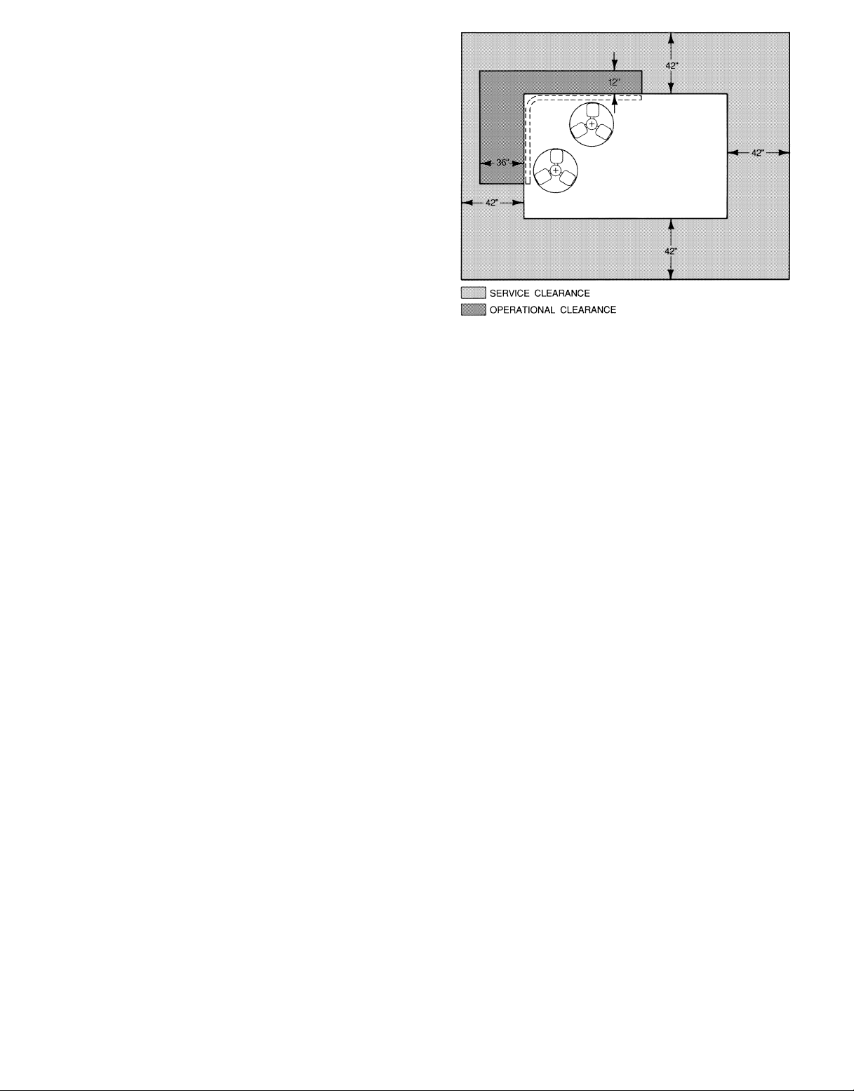
Maintain clearance around and above unit to provide minimum distance from combustible materials, proper airflow ,and
service access. See Fig. 2 and 3.
Minimum clearance to combustibles (when not using curb) is
0 in. on vertical discharge units and 1 in. on horizontal discharge units.
Minimum clearance to block walls or any other grounded surface is 42 in. on all sides.
Minimum clearance of 42 in. should be provided between units
on side with control box. Between unit and ungrounded surfaces, control box side, clearance is 36 inches.
Minimum clearance around outdoor coil is 12 in. one side and
36 in. the other side (side getting greater clearance is
optional).
Overhead minimum clearance is 60 in.
Do not install unit in an indoor location. Do not locate unit
air inlets near exhaust vents or other sources of contaminated air.
Although unit is weatherproof, guard against water from higher
level runoff and overhangs.
Slab mounted units should be at least 4 in. above the highest
expected water, flood, and runoff levels. Do not use the unit if
it has been under water.
B. Roof Curb Mount
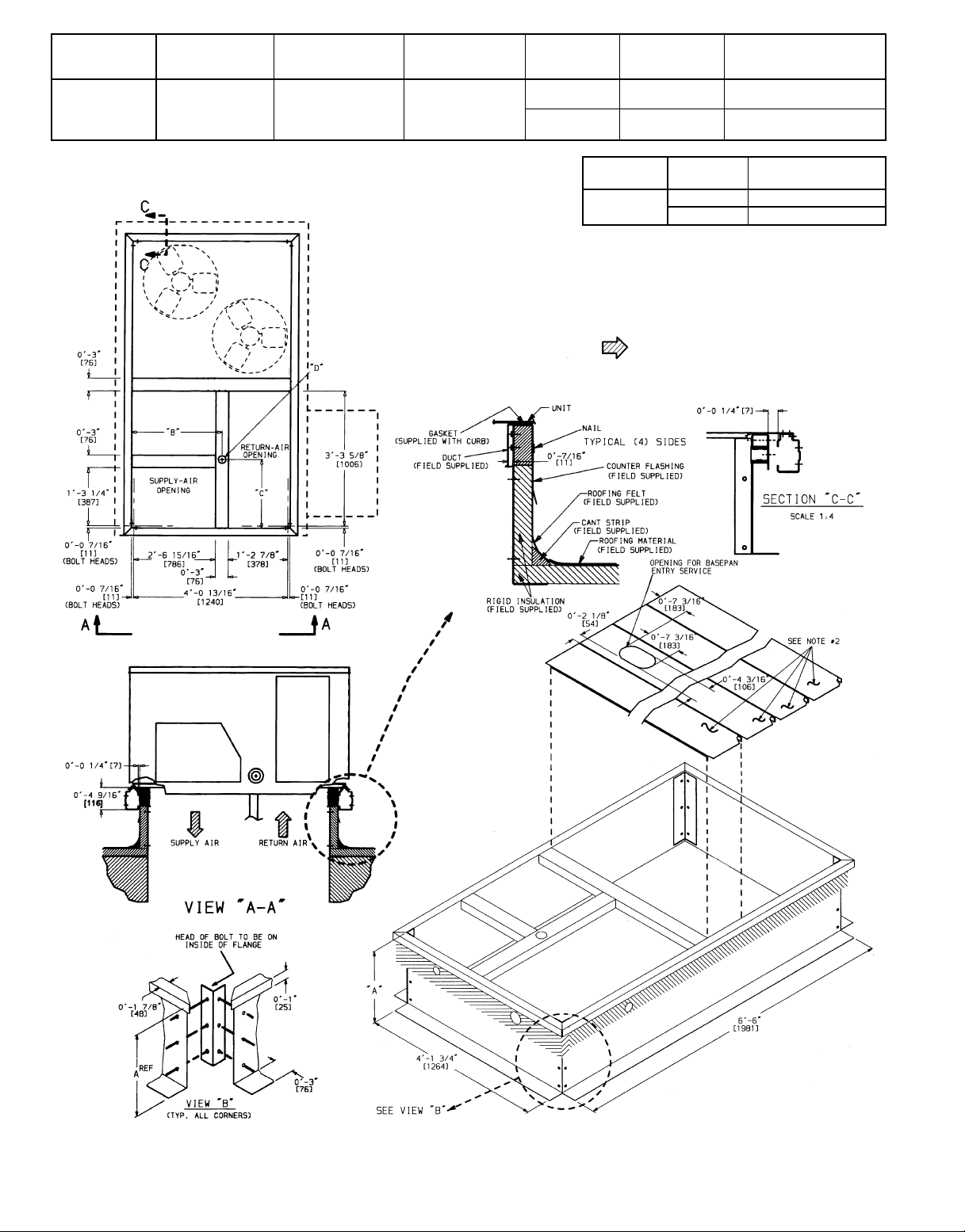
Assemble and install accessory roof curb in accordance with
instructions shipped with curb. See Fig. 4. Install insulation,
cant strips, roofing felt, and counter flashing as shown. Duct-
work must be attached to curb. If electric or control power is
to be routed through the basepan, attach the accessory thruthe-bottom connections to the basepan in accordance with the
accessory installation instructions. Accessory electric connections must be installed before unit is in place on roof curb.
IMPORTANT: The gasketing of the unit to the roof curb is
critical for water integrity. Install gasket with the roof curb
as shown in Fig. 4. Improperly applied gasket can also result
in air leaks and poor unit performance.
Curb should be level. Unit leveling tolerances are shown in
Fig. 5. This is necessary for unit drain to function
properly.
C. Slab Mount (Horizontal Units Only)
Provide a level concrete slab that extends a minimum of
6 in. beyond unit cabinet. Install a gravel apron in front of
outdoor-coil air inlet to prevent grass and foliage from obstructing airflow.
NOTE: Horizontal units may be installed on a roof curb if
required.
II. UNIT DUCT CONNECTIONS
On vertical units, secure all ducts to roof curb and building
structure. Do not connect ductwork to unit. On horizontal units,
duct flanges should be attached to horizontal openings and
all ductwork should be secured to flanges.
Fig. 3 — Service and Operational Clearances
Insulate and weatherproof all external ductwork, joints, and
roof openings with counter flashing and mastic in accordance
with applicable codes.
Ducts passing through an unconditioned space must be insulated and covered with a vapor barrier.
If a plenum return is used on a vertical unit, the return should
be ducted through the roof deck to comply with applicable
fire codes.
A minimum clearance to combustibles is not required
around ductwork on vertical discharge units. On horizontal
discharge units, a minimum clearance of 1 in. is required
for the first 12 in. of ductwork. Cabinet return-air static
shall not exceed –0.35 in. wg with Varislide™ economizer
−0.20 in. wg with PARABLADE economizer, or –0.45 in. wg
without economizer.
NOTE: Connection must be made to roof curb before unit is
set in place.
III. RIG AND PLACE UNIT
Inspect unit for transportation damage. File any claim with
transportation agency. Keep unit upright and do not drop.
Spreader bars are not required if top crating is left on unit.
Rollers may be used to move unit across a roof. Level by using unit frame as a reference. See Table 1 and Fig. 6 for additional information. Operating weight is shown in Fig. 6.
Lifting holes are provided in base rails as shown in Fig. 6.
Refer to rigging instructions on unit.
A properly positioned unit will have the following clearances
between unit and roof curb:
and base rails on each side and front of unit; 1
1
⁄4-in. clearance between roof curb
5
⁄32-in. clearance between roof curb and rear of unit. See Fig. 4, Views
A-A and C-C.
After unit is in position, remove polyethylene shipping wrapper and rigging skid.
—3—
Page 4
UNIT SIZE
549B
090,120 28-8
‘‘B’’ ‘‘C’’
7
⁄169 [827] 18-1015⁄169 [583] 13⁄49 [45]
‘‘D’’ALT
DRAIN HOLE
POWER CONTROL
3
⁄49 NPT
1
1
⁄49 NPT
1
⁄29 NPT
1
⁄29 NPT
CONNECTOR
ACCESSORY
PACKAGE
CRBTMPWR00A100
(Thru-the-Bottom)
CRBTMPWR00A200
(Thru-the-Bottom)
UNIT SIZE
549B
090,120
NOTES:
1. Roof curb accessory is shipped unassembled.
2. Insulated panels.
3. Dimensions in [ ] are in millimeters.
4. Roof curb: galvanized steel.
5. Attach ductwork to curb (flanges of duct rest on curb).
6. Service clearance 4 ft on each side.
‘‘A’’
18-29 [356] CRRFCURB003A00
28-09 [610] CRRFCURB004A00
ROOF CURB
ACCESSORY
7. Direction of airflow.
Fig. 4 — Roof Curb Details
—4—
Page 5
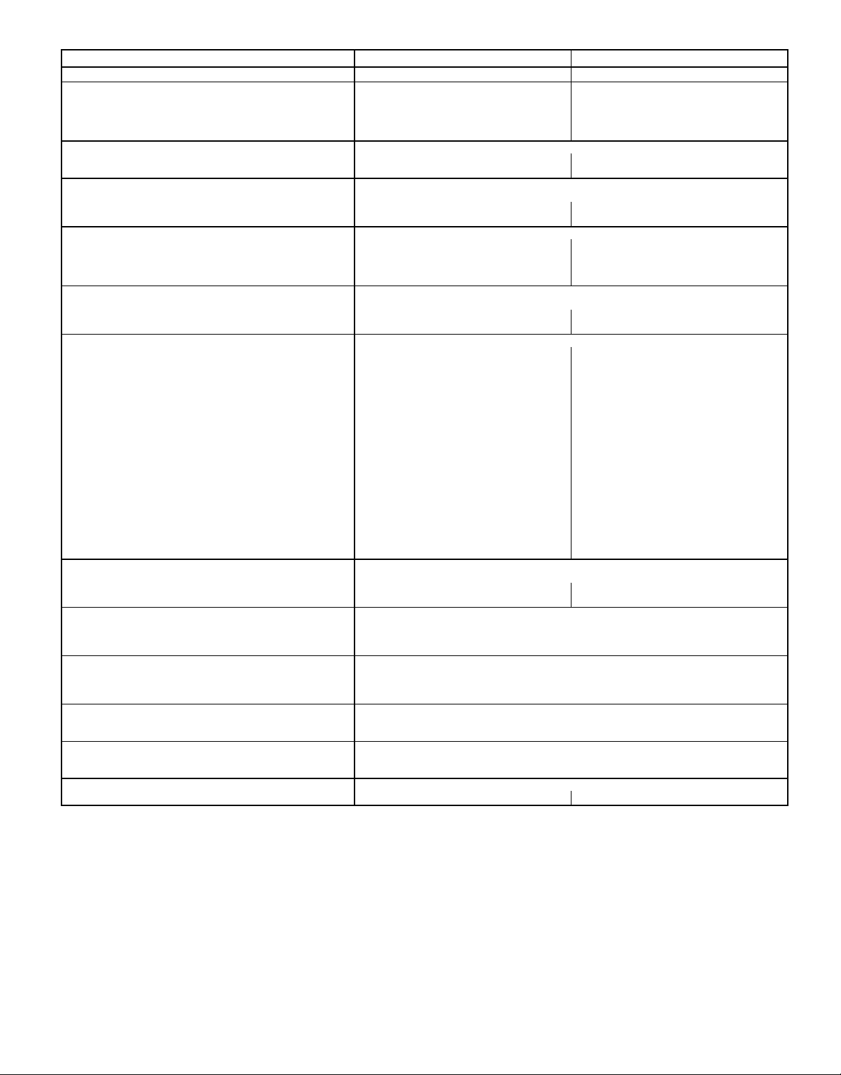
Table 1 — Specifications
UNIT 549B 090 120
1
⁄
1
⁄4...1100
7
⁄
8
2
Acutrol™ Feed Device
Acutrol Feed Device
1...16 x 25 x 1
NOMINAL CAPACITY (tons) 7
OPERATING WEIGHT (lb)
Unit 870 1000
With Varislide™ Economizer 914 1044
With PARABLADE Economizer 932 1062
Roof Curb 143 143
COMPRESSOR Scroll
Quantity 22
Oil (oz) (each compressor) 57 57
REFRIGERANT TYPE R-22
Operating Charge (lb-oz)
Circuit 1 5-3 9-11
Circuit 2 5-8 9-11
OUTDOOR FAN Propeller Type
Quantity...Diameter (in.) 2...22 2...22
Nominal Cfm 6500 7000
Motor Hp...Rpm
Watts Input (Total) 650 650
OUTDOOR COIL
Rows...Fins/in. 2...17 2...17
Total Face Area (sq ft) 20.5 25.1
INDOOR FAN Centrifugal Type, Belt Drive
Size (in.) 1...15 x 15 1...15 x 15
Nominal Cfm 3000 4000
Maximum Continuous Bhp 2.90 4.20
Motor Frame 56 56
Fan Rpm Range 725-925 860-1080
Motor Bearing Type Ball Ball
Maximum Fan Rpm 2100 2100
Motor Pulley Pitch Diameter A/B (in.) 3.4/4.4 4.0/5.0
Nominal Motor Shaft Diameter (in.)
Fan Pulley Pitch Diameter (in.) 8.0 8.0
Belt — Quantity...Type...Length (in.) 1...A...51 1...A...51
Pulley Center Line Distance (in.) 16.75-19.25 15.85-17.50
Speed Change per Full Turn of 50 45
Movable Pulley Flange (rpm)
Movable Pulley Maximum Full Turns 55
From Closed Position
Factory Setting — Full Turns Open 55
Factory Speed Setting (rpm) 725 860
Fan Shaft Diameter at Pulley (in.) 11
High-Efficiency Enhanced Copper Tubes, Lanced Aluminum Fins
INDOOR COIL High Efficiency Enhanced Copper Tubes, Aluminum Double-Wavy Fins,
Rows...Fins/in. 3...15 4...15
Total Face Area (sq ft) 8.9 11.1
HIGH-PRESSURE SWITCH (psig)
Standard Compressor Internal Relief 450±50
Cutout 428
Reset (Auto.) 320
LOSS-OF-CHARGE/LOW-PRESSURE
SWITCH (Liquid Line) (psig)
Cutout 7±3
Reset (Auto.) 22±7
FREEZE-PROTECTION THERMOSTAT
Opens (F) 30±5
Closes (F) 45±5
OUTDOOR-AIR INLET SCREENS Cleanable
Quantity...Size (in.) 1...20 x 25 x 1
RETURN-AIR FILTERS Throwaway
Quantity...Size (in.) 4...16 x 20 x 2 4...20 x 20 x 2
10
1
⁄4...1100
7
⁄
8
LEGEND
Bhp — Brake Horsepower
—5—
Page 6
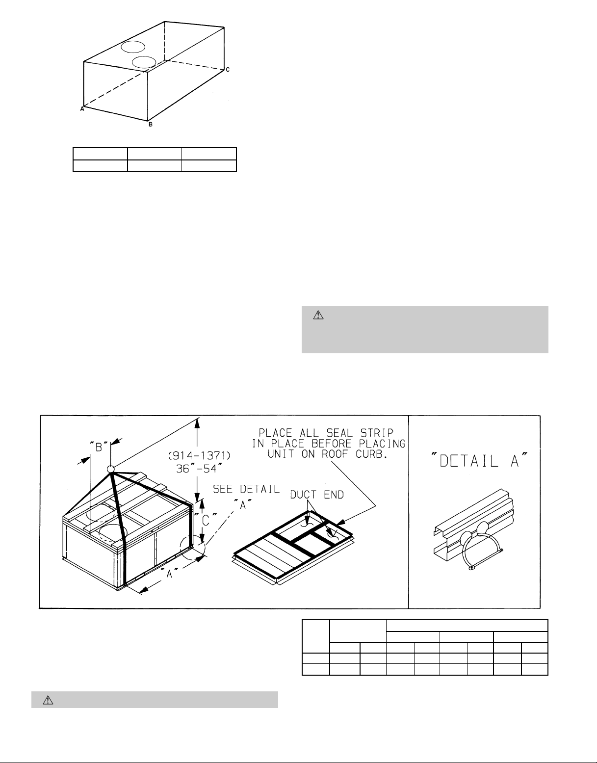
MAXIMUM ALLOWABLEDIFFERENCE (in.)
A-B B-C A-C
0.5 1.0 1.0
Fig. 5 — Unit Leveling Tolerances
IV. FIELD CONNECTIONS
A. External Trap Condensate Drain
The unit’s
3
⁄4-in. condensate drain connections are located
at the bottom and end of the unit. Unit discharge connections do not determine the use of drain connections; either
drain connection can be used with vertical or horizontal
applications.
When using the standard end drain connection, make sure
the plug in the alternate bottom connection is tight before
installing the unit.
To use the bottom drain connection for a roof curb installation, relocate the factory-installed plug from the bottom
connection to the end connection. See Fig. 7. The piping for
the condensate drain and external trap can be completed
after the unit is in place.
All units must have an external trap for condensate drainage. Install a trap at least 4-in. deep and protect against freezeup. See Fig. 8. If drain line is installed downstream from the
external trap, pitch the line away from the unit at 1 in. per
10 ft of run. Do not use a pipe size smaller than the unit
connection.
B. Field Duct Connections
NOTE: The design and installation of the duct system must
be in accordance with NFPA standards for the installation of
nonresidence-type air conditioning and ventilating systems,
NFPA No. 90A, or residence-type, NFPA No. 90B, and/or
local codes and ordinances.
Adhere to the following criteria when selecting, sizing, and
installing the duct system:
1. Remove appropriate panels from unit to obtain either
horizontal or vertical discharge. If units are installed in
horizontal discharge applications, remove vertical discharge duct covers, save screws, and install covers on
vertical duct openings.
2. Select and size ductwork, supply-air registers, and returnair grilles according to ASHRAE (American Society
of Heating, Refrigeration and Air Conditioning Engineers) recommendations.
CAUTION:
When drilling the duct system fastening
holes into the side of the unit for duct flanges, use extreme care not to puncture the coil or coil tubes. See
Fig. 9.
NOTES:
1. Dimension in ( ) is in millimeters.
2. Hook rigging shackles through holes in base rail, as shown in detail
9A.9 Holes in base rails are centered around the unit center of gravity. Use wooden top skid when rigging to prevent rigging straps from
damaging unit.
3. Unit weights do not include economizer. See Table 1 for economizer
weights.
CAUTION: All panels must be in place when rigging.
Fig. 6 — Rigging Details
—6—
OPERATING
UNIT
549B
090 870 395 87.38 2219 40.25 1022 41.31 1050
120 1000 454 87.38 2219 40.25 1022 49.31 1253
WEIGHT
lb kg in. mm in. mm in. mm
(A((B((C(
DIMENSIONS
Page 7
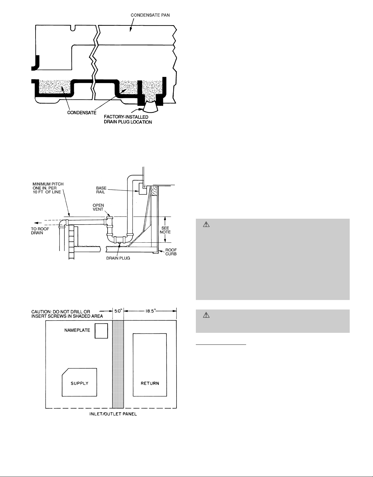
NOTE: Drain plug is shown in factory-installed position.
Fig. 7 — Condensate Drain Pan
3. Use flexible transition between rigid ductwork and unit
to prevent transmission of vibration. The transition may
be screwed or bolted to duct flanges. Use suitable gaskets to ensure weather- and airtight seal.
4. When horizontal return is used, install external fieldsupplied air filters in return-air ductwork where they
are easily accessible for service. Recommended filter sizes
are shown in Table 1.
5. For horizontal applications, be sure ductwork does not
cover nameplate.
6. Size all ductwork for maximum required airflow (either
heating or cooling) for unit being installed.Avoidabrupt
duct size increases or decreases.
7. Adequately insulate and weatherproof all ductwork
located outdoors. Insulate ducts passing through unconditioned space, and use vapor barrier in accordance with
latest issue of SMACNA (Sheet Metal and Air Conditioning Contractors National Association) and ACCA
(Air Conditioning Contractors of America) minimum
installation standards for heating and air conditioning
systems. Secure all ducts to building structure.
A minimum clearance to combustibles is not required
around ductwork on vertical discharge units. On horizontal discharge units, a minimum clearance of 1 in. is
required for the first 12 in. of ductwork.
8. Flash, weatherproof, and vibration isolate all openings
in building structure in accordance with local codes and
good building practices.
NOTE: Trap should be deep enough to offset maximum unit static diffrence. A 4-in. trap is recommended.
Fig. 8 — External Trap Condensate Drain
Fig. 9 — Location of Coil Area
Not to be Drilled
C. Electrical Connections
WARNING:
The unit cabinet must have an uninterrupted, unbroken, electrical ground to minimize the
possibility of personal injury if an electrical fault should
occur. This ground may consist of electrical wire connected to the unit ground lug in the control compartment, or conduit approved for electrical ground when
installed in accordance with NEC ANSI (American
National Standards Institute)/NFPA70-1990(inCanada,
Canadian Electrical Code CSA [Canadian Standards
Association] C22.1) and local electrical codes. Failure
to adhere to this warning could result in personal
injury.
CAUTION:
Failure to obey the following precautions could result in damage to the unit being
installed:
Field Power Supply
1. Make all electrical connections in accordance with NEC
ANSI/NFPA 70-1990 and local electrical codes governing such wiring. In Canada, all electrical connections must be in accordance with CSA Standard C22.1
Canadian Electrical Code Part One and applicable local
codes. Refer to unit wiring diagram.
2. A unit disconnect switch is required within sight
from the unit. The disconnect switch may be mounted
on the unit corner post (see Fig. 2). When mounting disconnect switch, be sure the unit rating plate is not
obstructed.
NOTE: A factory-installed disconnect switch is available.
—7—
Page 8
3. Use only copper or copper-clad conductor for connections between field-supplied electrical disconnect switch
and unit. The use of aluminum wire is not recommended. Maximum wire size is no. 2 AWG (American
Wire Gage) on units with heat(up to 34 kW). The maximum wire size is no. 2/0 AWG on units with heat (over
34 kW).
4. Units with accessory electric heat must also have the
correct single point box kit to meet UL (Underwriters’
Laboratories) requirements. Refer to installation instructions shipped with the accessory for more details.
5. Voltage to compressor terminals during operation must
be within voltage range indicated on unit nameplate (also
see Tables 2A and 2B). On 3-phase units, voltages between phases must be balanced within 2% and the current within 10%. Use the formula shown in Tables 2A
and 2B, Note 2 to determine the percent voltage imbalance. Operation on improper line voltage or excessive
phase imbalance constitutes abuse and may cause damage to electrical components. Such operation would invalidate any applicable warranty.
6. Insulate low-voltage wires for highest voltage contained within conduit when low-voltage control wires are
run in same conduit as high-voltage wires. Install conduit through side panel openings. For units without accessory electric heat, install conduit between disconnect
and control box.
7. Do not damage internal components when drilling through
any panel to mount electrical hardware, conduit, etc.
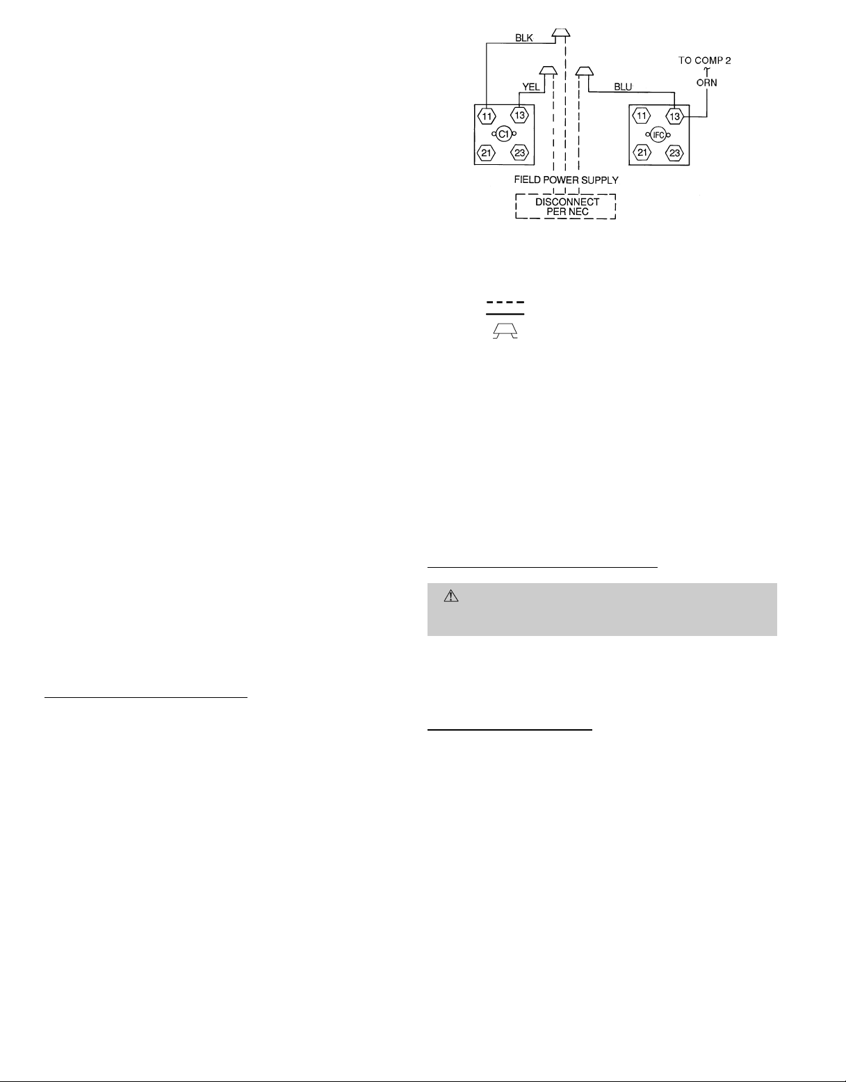
8. Install power lines to terminal connections as shown in
Fig. 10.
9. For units with accessory electric heat, refer to accessory
installation instructions for wiring the accessory.
During operation, voltage to compressor terminals must be
within range indicated on unit nameplate (see Tables 2A and
2B). On 3-phase units, voltages between phases must bebalanced within 2%, and the current within 10%. Use the formula shown in Tables 2A and 2B, Note 2 to determine the
percentage of voltage imbalance. Operation on improper line
voltage or excessive phase imbalance constitutes abuse and
may cause damage to electrical components. Such operation
would invalidate any applicable warranty.
High-Voltage Connections (Fig. 10)
The unit must have a separate electrical service with a field-
supplied, waterproof fused disconnect switch mounted at, or
within sight from, the unit. Refer to the unit rating plate for
maximum fuse/circuit breaker size and minimum circuit amps
(ampacity) for wire sizing. Be sure disconnect switch does not
obstruct unit rating plate. A factory-installed disconnect is
available.
The field-supplied disconnect switch box may be mounted on
the unit over the high-voltage inlet holein the control corner
panel.
Proceed as follows to complete the high-voltage connections
to the unit:
1. Connect ground lead to chassis ground connection when
using separate ground wire.
LEGEND
C—Contactor
COMP — Compressor
IFC — Indoor Fan Contactor
NEC — National Electrical Code
Field Wiring
Factory Wiring
Splice Connection (Factory-Supplied)
Fig. 10 — Power Wiring Connections
2. Pigtails are provided for field power connection. Use
factory-supplied splices or UL-approved copper/aluminum
connector .Install conduit connectors in side panel power
supply knockout openings indicated in Fig. 2. Route power
lines through connector to unit control box.
NOTE: If accessory thru-the-bottom power connections are
used, refer to the accessory installation instructions for information on power wiring. Refer to Fig. 2 for drilling holes
in basepan.
Special Procedures for 208-V Operation
DANGER: Make sure that the power supply to the
unit is switched off before making any wiring changes.
Electrical shock can cause personal injury or death.
For operation on 208 v, disconnect the black wire from the
230-v orange wire on the transformer and connect it to the
200-v red wire from the transformer. Insulate the end of the
orange wire.
Control Voltage Connections
Install a factory-approved room thermostat. See Table 3,
page 11.Locate the thermostat on an inside wall in the space
to be conditioned where it will not be subjected to either a
cooling or heating source or direct exposure to sunlight. Mount
the thermostat 4 to 5 ft above the floor.
NOTE: For wire runs up to 50 ft, use no. 18 AWG insulated
wire (35 C minimum). For 51 to 75 ft, use no. 16 AWG insulated wire (35 C minimum). For 76 to 155 ft, use no. 14 AWG
insulated wire (35 C minimum). All wire larger than no. 18
AWG cannot be connected directly tothe thermostat and will
require a junction box and splice at the thermostat.
—8—
Page 9
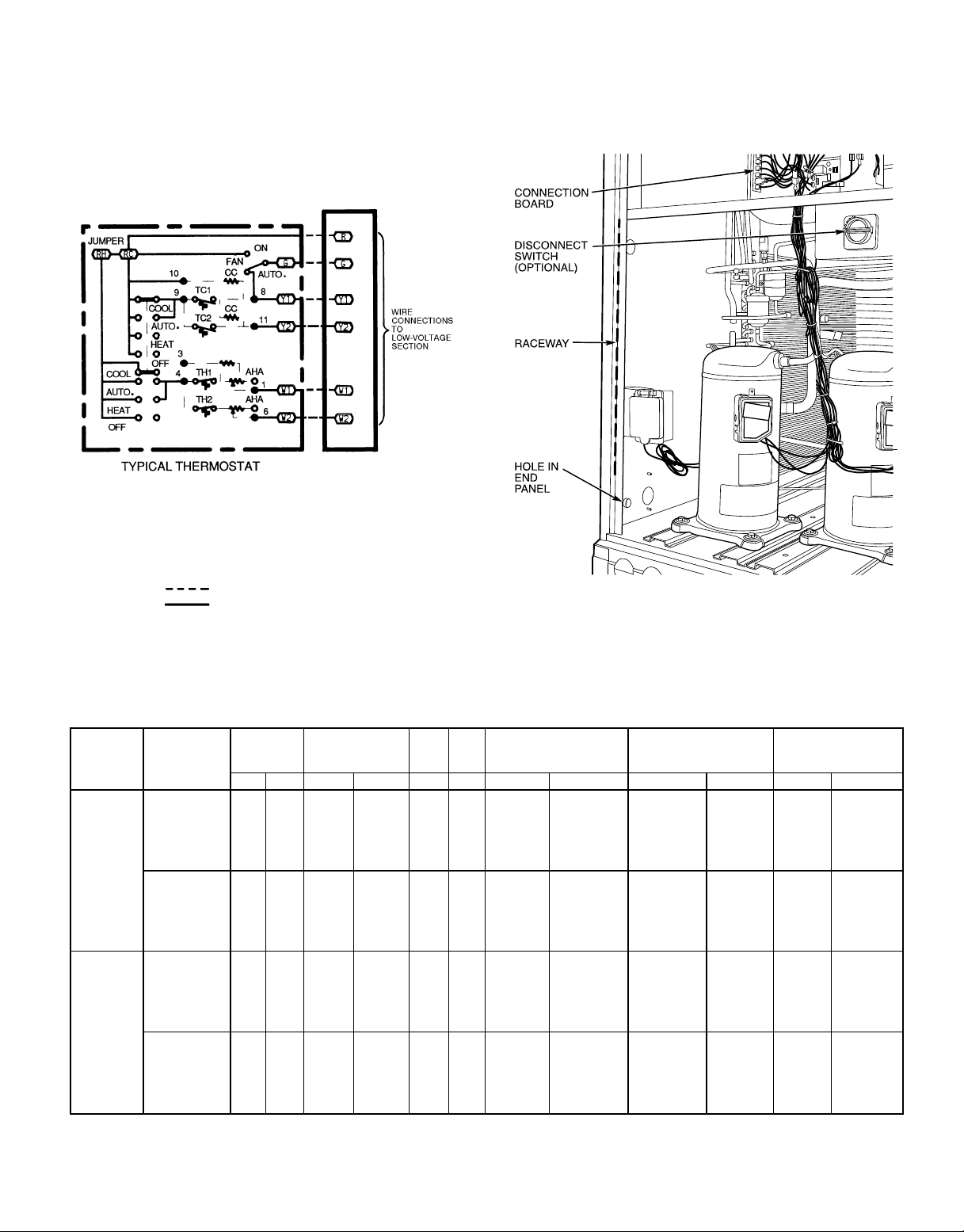
Route thermostat cable or equivalent single leads of colored
wire from subbase terminals to low-voltage connections on
unit (shown in Fig. 11) as described in Steps 1 through 4
below.
1. If unit is mounted on roof curb and accessory thru-thebottom service connections are used, route wire through
basepan.
2. Pass control wires through the hole provided on unit (see
connection D in Connection Sizes table in Fig. 2).
LEGEND
AHA — Adjustable Heat Anticipator
CC — Cooling Compensator
RC — 24 V Cooling
RH — 24 V Heating
TC — Thermostat-Cooling
TH — Thermostat-Heating
Field Wiring
Factory Wiring
Fig. 11 — Low-Voltage Connections With or
Without Economizer
3. Feed wire through the raceway built into the corner post
to the 24-v barrier located on the left side of the control
box. See Fig. 12. The raceway provides the ULrequired
clearance between the high- and low-voltage wiring.
4. Connect thermostat wires to screw terminals of lowvoltage connector (see Fig. 11).
Fig. 12 — Field Control Wiring Raceway
UNIT
549B
090
1
(7
⁄2Tons)
120
(10 Tons)
Table 2A — Electrical Data (Units Without Electrical Convenience Outlet)
NOMINAL
VOLTAGE
(V-Ph-Hz)
208/230-3-60 187 254 12.4 88.0 1.4 7.5
460-3-60 414 508 6.4 44.0 0.7 3.4
208/230-3-60 187 254 19.3 123.0 1.4 10.6
460-3-60 414 508 10.0 62.0 0.7 4.8
VOLTAGE
RANGE
Min Max RLA LRA FLA FLA kW† FLA MCA MOCP FLA LRA
COMPRESSOR OFM IFM ELECTRIC HEAT* POWER SUPPLY
—/—
7.8/10.4
12.0/16.0
18.6/24.8
24.0/32.0
31.8/42.4
—
13.9
16.5
27.8
33.0
41.7
—/—
7.8/10.4
12.0/16.0
24.0/32.0
31.8/42.4
37.6/50.0
—
16.5
27.8
33.0
41.7
50.0
—/—
21.7/ 25.0
33.3/ 38.5
51.6/ 59.7
66.6/ 77.0
88.3/102.0
—
16.7
19.8
33.4
39.7
50.2
—/—
21.7/ 25.0
33.3/ 38.5
66.6/ 77.0
88.3/102.0
104.4/120.3
—
19.8
33.4
39.7
50.2
60.1
38.2/ 38.2
65.3/ 69.5
79.8/ 86.3
102.7/112.8
121.5/134.5
148.6/165.7
19.2
40.1
44.0
61.0
68.8
82.0
56.8/ 56.8
84.0/ 88.1
98.5/105.0
140.1/153.1
167.2/184.3
187.3/177.1
28.7
53.3
70.5
78.3
91.5
88.8
40/ 40**
70/ 70
80/ 90
110/125
125/150
150/175
20**
45**
45**
70
70
90
60/ 60**
90/ 90
100/110
150/175
175/200
200/200
30**
60**
80
80
100
100
MINIMUM UNIT
DISCONNECT
SIZE
40/ 40
65/ 69
79/ 85
100/109
117/129
142/158
60/ 60
85/ 89
98/104
136/148
161/177
180/198
20
39
43
59
66
78
30
53
69
76
88
99
242/242
264/267
275/281††
294/302††
309/319††
330/344††
337/337
358/362††
370/375††
403/414††
425/439††
441/457††
121
138
141
155
161
171
170
189
203
209
220††
230††
—9—
Page 10
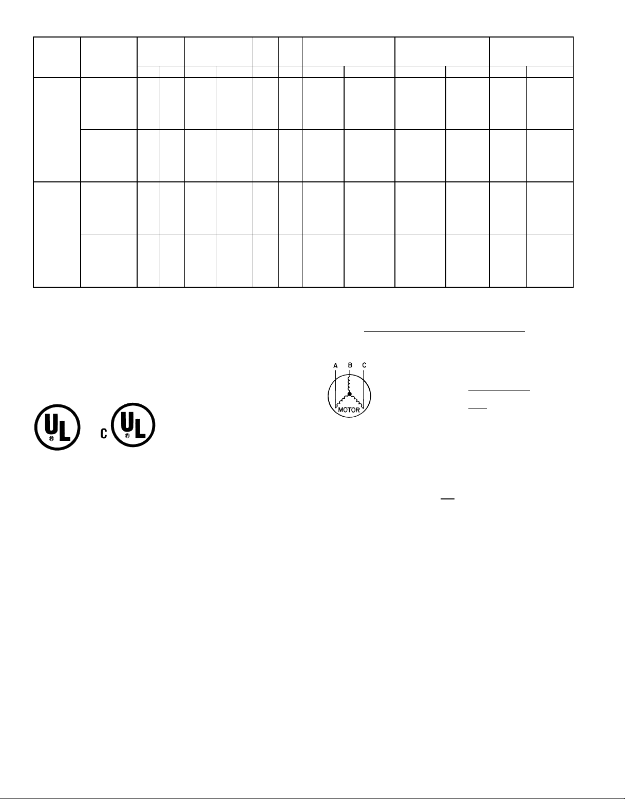
Table 2B — Electrical Data (Units With Electrical Convenience Outlet)
UNIT
549B
NOMINAL
VOLTAGE
(V-Ph-Hz)
VOLTAGE
RANGE
COMPRESSOR OFM IFM ELECTRIC HEAT* POWER SUPPLY
Min Max RLA LRA FLA FLA kW† FLA MCA MOCP FLA LRA
208/230-3-60 187 254 12.4 88.0 1.4 7.5
009
1
(7
⁄2Tons)
460-3-60 414 508 6.4 44.0 0.7 3.4
208/230-3-60 187 254 19.3 123.0 1.4 10.6
120
(10 Tons)
460-3-60 414 508 10.0 62.0 0.7 4.8
LEGEND AND NOTES TO TABLES 2A AND 2B
LEGEND
FLA — Full Load Amps
HACR — Heating, Air Conditioning and Refrigeration
IFM — Indoor Fan Motor
LRA — Locked Rotor Amps
MCA — Minimum Circuit Amps
MOCP — Maximum Overcurrent Protection
NEC — National Electrical Code
OFM — Outdoor Fan Motor
RLA — Rated Load Amps
*Used to determine minimum disconnect per NEC.
†Heater capacity (kW) is based on heater voltage of 208 v, 240 v,
or 480 v. If power distribution voltage to unit varies from rated heater
voltage, heater kW will vary accordingly.
**Fuse or HACR circuit breaker.
††Factory-installed disconnect is not available for these units when elec-
tric heat package is installed.
NOTES:
1. In compliance with NEC requirements for multimotor and combination load and equipment (refer to NEC Articles 430 and 440), the
overcurrent protective device for the unit shall be fuse or HACR breaker.
2. Unbalanced 3-Phase Supply Voltage
Never operate a motor where a phase imbalance in supply voltage is
greater than 2%.
age of voltage imbalance.
Use the following formula to determine the percent-
MINIMUM UNIT
DISCONNECT
SIZE
—/—
7.8/10.4
12.0/16.0
18.6/24.8
24.0/32.0
31.8/42.4
—
13.9
16.5
27.8
33.0
41.7
—/—
7.8/10.4
12.0/16.0
24.0/32.0
31.8/42.4
37.6/50.0
—
16.5
27.8
33.0
41.7
50.0
—/—
21.7/ 25.0
33.3/ 38.5
51.6/ 59.7
66.6/ 77.0
88.3/102.0
—
16.7
19.8
33.4
39.7
50.2
—/—
21.7/ 25.0
33.3/ 38.5
66.6/ 77.0
88.3/102.0
104.4/120.3
—
19.8
33.4
39.7
50.2
60.1
43.0/ 43.0
70.1/ 74.3
84.6/ 91.1
107.5/117.6
126.3/139.3
153.4/170.5
21.4
42.3
46.1
63.1
71.0
84.1
61.6/ 61.6
88.8/ 92.9
103.3/109.6
144.9/157.9
172.0/189.1
192.1/181.9
30.9
55.6
72.6
80.5
93.6
91.0
45/ 45**
80/ 80
90/100
110/125
150/150
175/175
25**
45**
50**
70
80
90
70/ 70
90/100
110/110
150/175
175/200
200/200
35**
60**
80
90
100
100
46/ 46
71/ 75
84/ 90
105/115
122/134
147/163
23
42
46
61
68
80
65/ 65
90/ 94
104/110
142/154
167/183
185/204
33
55
71
78
90
102
247/247
269/272
280/285††
298/307††
313/324††
335/349††
123
140
143
157
163
174
341/341
363/366††
375/380††
408/418††
430/443††
446/462††
172
191
205
211
222††
232††
% Voltage Imbalance
= 100 x
max voltage deviation from average voltage
average voltage
EXAMPLE: Supply voltage is 460-3-60
AB = 452 v
BC = 464 v
AC = 455 v
Average Voltage =
452 + 464 + 455
1371
=
3
3
= 457
Determine maximum deviation from average voltage:
(AB) 457 – 452=5v
(BC) 464 – 457=7v
(AC) 457 – 455=2v
Maximum deviation is 7 v.
Determine percentage of voltage imbalance:
% Voltage imbalance = 100 x
7
457
= 1.53%
This amount of phase imbalance is satisfactory as it is below the
maximum allowable 2%.
IMPORTANT: If the supply voltage phase imbalance is more than 2%
contact your local electric utility company immediately.
—10—
Page 11
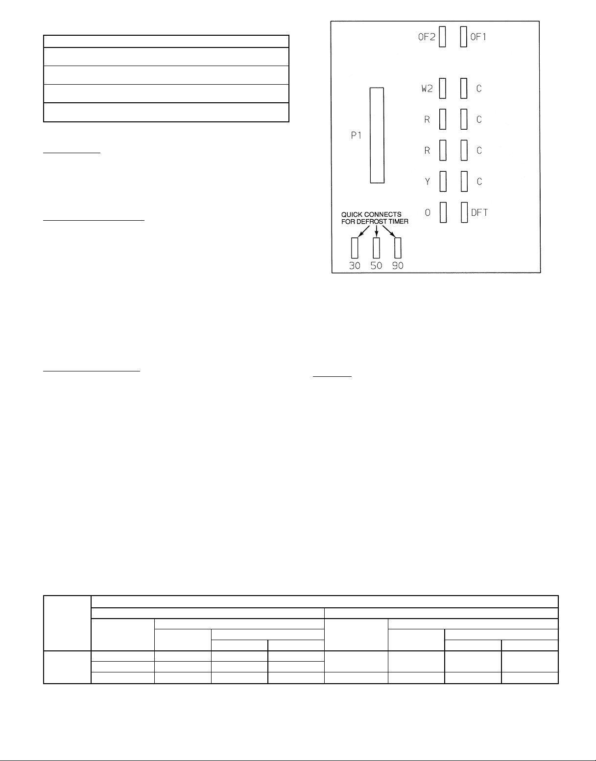
Table 3 — Thermostats
TYPE
Manual Changeover (Standard)
2 Heat/2 Cool
Auto. Changeover (Standard)
2 Heat/2 Cool
Manual Changeover (Electronic Setback)
1 Heat/2 Cool
Auto. Changeover (Electronic Setback)
2 Heat/2 Cool
Defrost Board
The defrost board timer cycle is set to 30 minutes. To change
the cycle time, remove the wire from defrost board connected
to the 30 minute quick-connect. See Fig. 13. Connect the wire
to the 50 or 90 minute quick-connects on the defrost board
depending on the desired defrost time.
Heat Anticipator Setting
The room thermostat heat anticipator must be properly ad-
justed to ensure proper heating performance. Set the heat
anticipator using Table 4.
Failure to make a proper heat anticipator adjustment may
result in improper operation, discomfort to the occupants of
the conditioned space, and inefficientenergy utilization; however,the required setting may be changed slightly to provide
a greater degree of comfort for a particular installation.
D. Accessory Installation
At this time, any required accessories should be installed on
the unit. Installation information can be found in the accessory installation book.
Accessory Electric Heat
Each heater package consists of one or more electric heater
module kits and requires the correct single point kit. Refer to
Accessory Electric Heater and Single Point Box Installation
Instructions shipped with the heater for installation details.
NOTE: Factory-installed disconnect switch cannot be used with
some electric heater applications. See Tables 2A and 2B for
more information.
E. Disconnect Switch
The optional disconnect switch is non-fused. The switch has
the capability of being locked in place for safety purposes.
F. Optional Varislide™ Economizer
The optional economizer hood assembly is packaged and shipped
in the filter section. Damper blades and control boards are
installed at the factory and the economizer is shipped in the
vertical discharge position.
Fig. 13 — Defrost Board
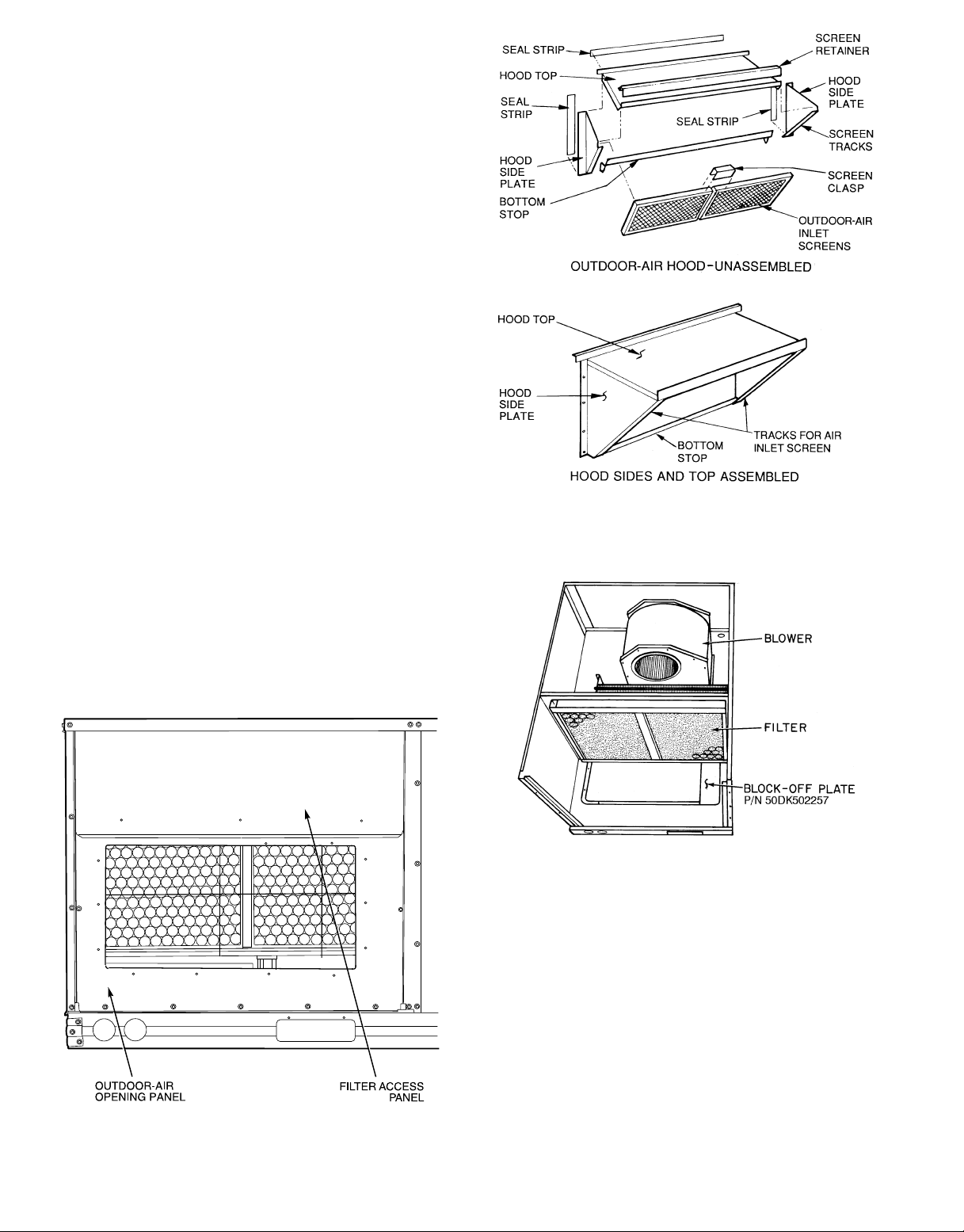
NOTE: Horizontal discharge block-off plate is shipped with
the air hood package. If unit is to be used for vertical discharge applications, discard this plate.
Assembly
1. Determine if ventilation air is required in building. If
so, determine the minimum amount to be supplied by
each unit and record quantity of ventilation air needed
for use in Step 8.
2. Remove filter access panel by raising panel and swinging panel outward. Panel is now disengaged from track
and can be removed. No tools are required to remove
filter access panel. Remove outdoor-air opening panel.
Save panels and screws. See Fig. 14. Remove optional
outdoor-air damper hood package from filter section.
3. Assemble outdoor-air hood top and side plates as shown
in Fig. 15. Install seal strips on hoop top and sides.
Put aside screen retainer and retainer screw for later
assembly. Do not attach hood to unit at this time.
UNIT
549B
*kW is based on 240 v and 480 v.
Heater
kW*
10.4, 16.0 0.3 NA NA
32.0, 24.8 0.6 0.3 0.3
42.4, 50.0 0.9 0.6 0.3 41.7, 50.0 0.6 0.3 0.3
Table 4 — Heat Anticipator Settings
UNIT VOLTAGE
208/230 460
1-Stage
Configuration
2-Stage
Stage 1 Stage 2 Stage 1 Stage 2
Heater
kW*
13.9, 16.5
27.8, 33.0
—11—
Configuration
1-Stage
0.3 NA NA
2-Stage
Page 12
4. On 120 units, install vertical discharge blockoff plate
over duct openings. See Fig. 16.
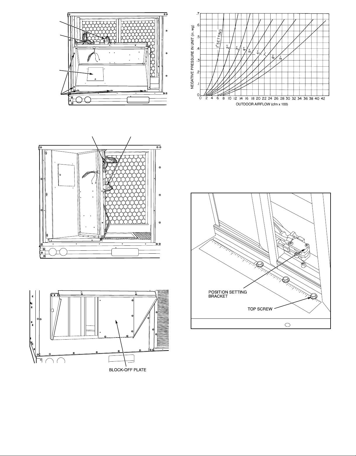
5. Slide economizer into unit and secure with screws. See
Fig. 17.
NOTE: Be sure to engage rear economizer flange under tabs
in vertical return-air opening.
6. To convert to horizontal discharge application:
a. Rotate the economizer 90 degrees until the econo-
mizer motor faces the outdoor section (see Fig. 18).
b. Rotate the barometric relief damper cover
90 degrees.
c. Install horizontal discharge block-off plate over the
opening on the access panel. (Block-off plate MUST
be installed before installing hood assembly.) See
Fig. 19.
7. Insert economizer plug into economizer harness. Remove tape from barometric relief damper. See Fig. 17.
8. If ventilation air is not required, proceed to Step 9. If
ventilation air is required, determine the minimum position setting for required airflow. See Fig. 20. Adjust
minimum position setting by adjusting the screws on
the position setting bracket. See Fig. 21. Slide bracket
until the top screw is in the position determined by
Fig. 20. Tighten screws.
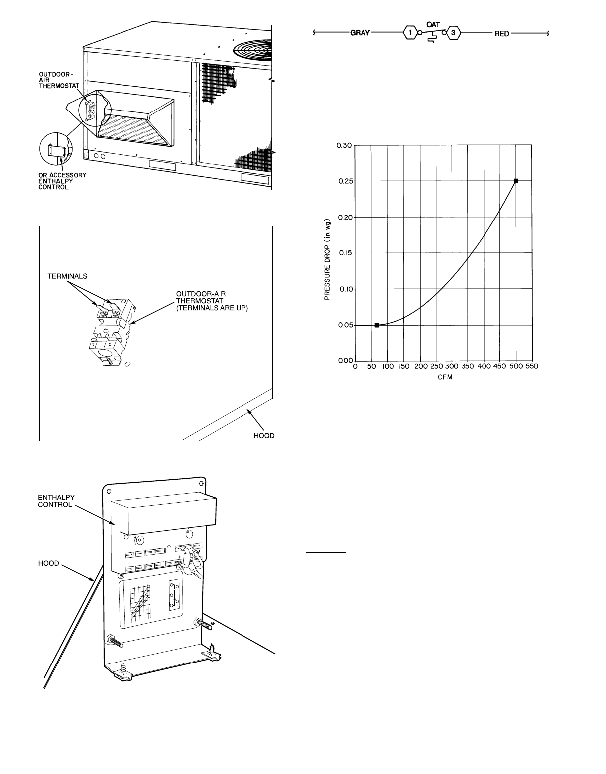
9. Remove tape from outdoor-air thermostat (OAT). Fasten OAT to inside of hood using screws andspeed clips
provided. See Fig. 22. Make sure OAT terminals are
positioned up.
10. Replace outdoor-air opening panel using screws from
Step 2. Replace filter access panel. Ensure the filter
access panel slides along the tracks and is securely
engaged.
11. Fasten hood top and side plate assembly to outdoor-air
opening panel with screws provided.
12. Place knob supplied with economizer on OAT. See
Fig. 22. Set for 3° F below indoorroom thermostat setting. If accessory enthalpy control (EC) is used in place
Fig. 15 — Outdoor-Air Hood Details
Fig. 14 — Panel Locations
Fig. 16 — Vertical Discharge Block-Off Plate
(Size 120 Only)
of OAT, see instructions shipped with EC for installation and adjustment. See Fig. 22.
13. Connect OAT per Fig. 23.
14. Slide outdoor-air inlet screens into screen track on hood
side plate. While holding screens in place, fasten screen
retainer to hood using screws provided.
NOTE: Refer to Fig. 24 for economizer barometric relief damper
characteristics.
—12—
Page 13
ECONOMIZER
MOTOR
ECONOMIZER
CONTROL BOARD
WIRING
HARNESS
BAROMETRIC
RELIEF
DAMPER
ECONOMIZER
MOUNTING
SCREWS
Fig. 17 — Varislide™ Economizer Installed in Unit
ECONOMIZER CONTROL BOARD
WIRING HARNESS
ECONOMIZER MOTOR
Fig. 18 — Horizontal Varislide Economizer Installation
(90 Degree Rotation)
EXAMPLE:
Given —
Negative Pressure ..........................0.01 in. wg
Outdoor Air ................................1100cfm
Determine — Setting = 6
Fig. 20 — Varislide Economizer Minimum
Position Setting
9
8
7
6
5
4
3
2
1
0
Fig. 19 — Horizontal Discharge Block-Off Plate
Fig. 21 — Varislide Economizer Minimum
Damper Setting
—13—
Page 14
LEGEND
OAT — Outdoor-Air Thermostat
NOTE: See unit wiring diagram for more details.
Fig. 23 — Wiring Connections for Outdoor-Air
Thermostat
Fig. 24 — Varislide Economizer Barometric
Relief Damper Characteristics
G. Optional PARABLADE Economizer
The optional PARABLADEeconomizer hood assembly is packaged and shipped in the filter section. Damper blades and
control boards are installed at the factory and the economizer is shipped in the vertical discharge position.
NOTE: Horizontal discharge block-off plate is shipped with
REV. B
CONTACTS SHOWN IN HIGH ENTHALPY
OR UNPOWERED STATE
B
198818A
C
TR
D
S
S
O
5
ENTHALPY
3
TR
24VAC
2
CONTROL
TR1
1
MINIMUM
POSITION
OPEN
1
3
T
P
2
T1
4
P1
CONTACT RATINGS: 1.5A RUN, 3.5A IN
RUSH AT 24VAC
%
H
U
M
I
D
I
T
Y
90
70
60
30
10
CW–SETPOINTS–CCW
D
50
DAMPER
C
OUTDOOR TEMP.
OPEN
55
B
A
60
65
70
°F
3 mA MIN. AT 11 VDC
DAMPER
CLOSED
75
80
85
97-3672
REV.
the air hood package. The PARABLADE economizer can only
be used for vertical discharge applications. Discard this plate.
Assembly
1. Determine if ventilation air is required in building. If
so, determine the minimum amount to be supplied by
each unit and record quantity of ventilation air needed
for use in Step 7.
2. Remove filter access panel by raising panel and swinging panel outward. Panel is now disengaged from track
and can be removed. No tools are required to remove
filter access panel. Remove outdoor-air opening panel.
See Fig. 14. Save panels and screws. Remove optional
economizer so the outdoor-air damper hood package can
be removed from the filter section.
Fig. 22 — Varislide™ Economizer Outdoor-Air
Thermostat/Enthalpy Control Installation
—14—
Page 15
3. Assemble outdoor-air hood top and side plates as shown
in Fig. 15. Install seal strips on the hood top and sides.
Put aside screen retainer and retainer screw for later
assembly. Do not attach hood to unit at this time.
4. On 120 units, install vertical discharge blockoff plate
over duct openings. See Fig. 16.
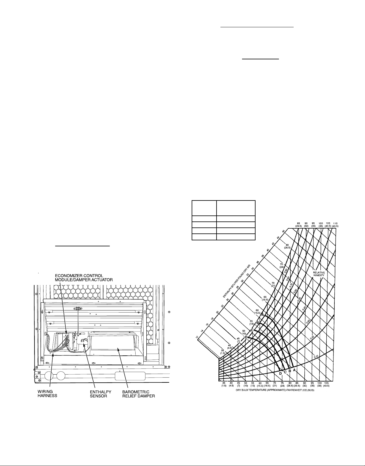
5. Slide economizer into unit and secure with screws. See
Fig. 25.
NOTE: Be sure to engage rear economizer flange under tabs
in vertical return-air opening.
6. Insert economizer plug into economizer harness. Remove tape from barometric relief damper. See Fig. 25.
7. If ventilation air is not required, proceed to Step 8. If
ventilation air is required, perform the following:
a. Make sure the factory-installed jumper is in place
across terminals P and P1 on the economizer logic
module. T and T1 should be disconnected during
adjustment.
b. The 2 potentiometers with slots for adjustment are
located on the face of the economizer logic module.
Turn the lower potentiometer fully clockwise. The
damper should be fully closed. Turn the potentiometer gradually counterclockwise until the desired
position is reached.
c. Connect T and T1 to the 24 V power supply.
d. After installation is complete, calculate the mini-
mum airflow across the economizer.To calculate the
minimum airflow, the following data is needed: to-
tal cfm (cfm3), temperature of the total cfm (T3),
temperature of the return air (T2), and tempera-
ture of the entering outside air (T1). Cfm1is the
outside air cfm, which will be the minimum airflow.
Insert the data into the following equations:
T1(cfm1)+T2(cfm2)
cfm
3
=T
3
cfm2= (cfm3– cfm1)
Therefore:
T1(cfm1)+T2(cfm3– cfm1)
cfm
3
=T
3
Use this equation to determine cfm1, which is the
minimum airflow across the economizer.
cfm1=
(T3–T2) cfm
(T1–T2)
3
If cfm1does not match the desired minimum airflow from Step 1, readjust the minimum position setting screw.
8. Determine the enthalpy changeover set point from
Fig. 26. The enthalpy changeover set point should be
set to return the outdoor air damper to the minimum
position when enthalpy rises above the set point. The
settings are A, B, C, and D. Set the enthalpy changeover per the setting in Fig. 26.
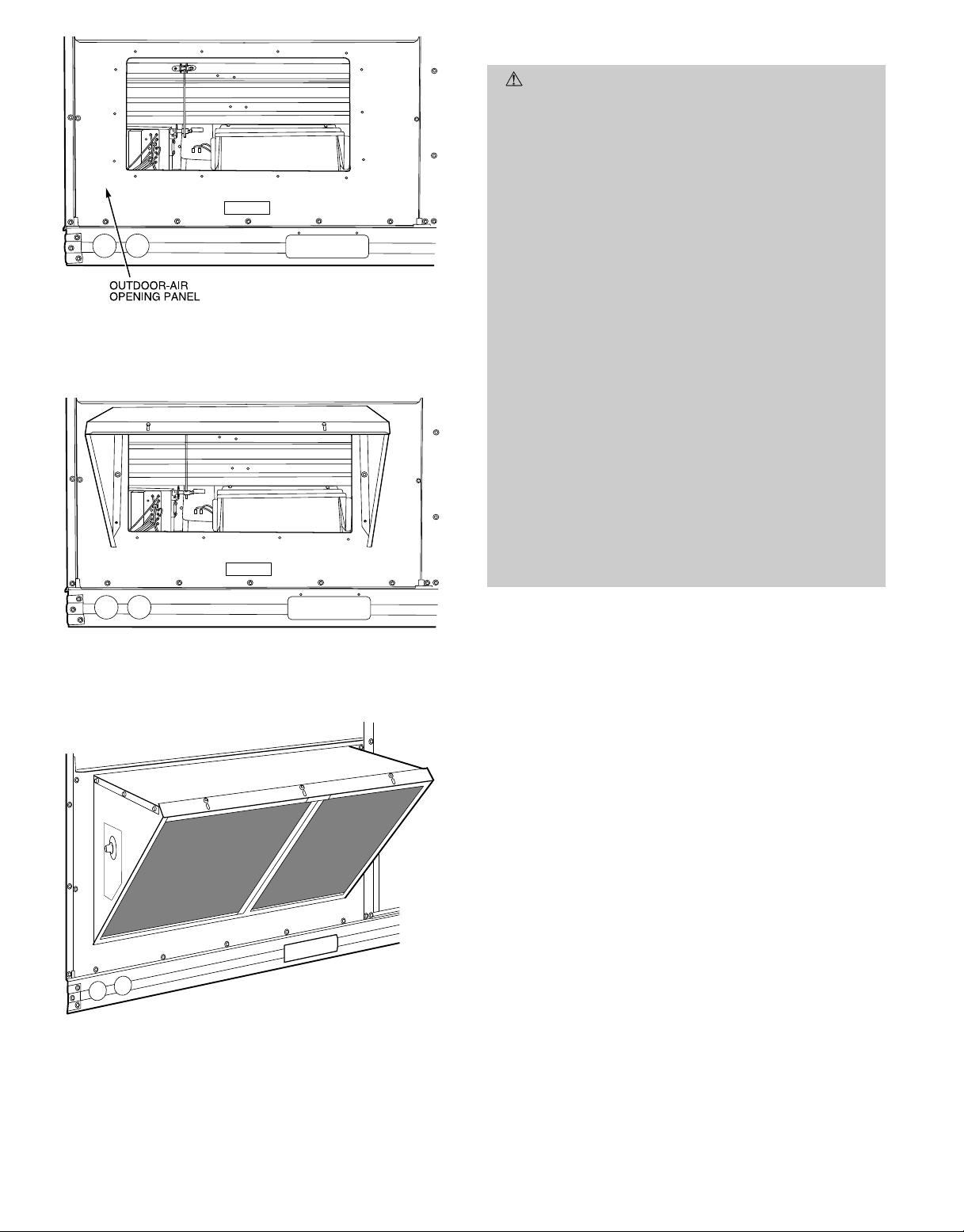
9. Replace outdoor-air opening panel using screws from
Step 2. Replace filter access panel. Ensure the filter
access panel slides along the tracks and is securely engaged. See Fig. 27.
10. Fasten hood and side plate assembly (Fig. 28) to outdoorair opening panel with screws provided.
11. Slide outdoor-air inlet screens into screen track on hood
side plate. While holding screens in place, fasten screen
retainer to hood using screws provided. See Fig. 29.
CONTROL
CURVE
CONTROL POINT
(APPROX DEG.)
A 73 [23]
B 70 [21]
C 67 [19]
D 63 [17]
AT 50% RH
Fig. 25 — PARABLADE Economizer Installed in Unit
Fig. 26 — Enthalpy Settings for PARABLADE
Economizer
—15—
Page 16
PRE-START-UP
Fig. 27 — Panels Reinstalled On Unit
WARNING:
ings could result in serious personal injury:
1. Follow recognized safety practices and wear pro-
tective goggles when checking or servicing refrigerant system.
2. Do not operate compressor or provide any electric
power to unit unless compressor terminalcover is
in place and secured.
3. Do not remove compressor terminal cover until all
electrical sources have been disconnected.
4. Relieve all pressure from system before touching
or disturbing anything inside terminal box if
refrigerant leak is suspected around compressor
terminals.
5. Never attempt to repair soldered connection while
refrigerant system is under pressure.
6. Do not use torch to remove any component. Sys-
tem contains oil and refrigerant under pressure.
To remove a component, wear protective goggles
and proceed as follows:
a. Shut off electrical power to unit.
b. Recover refrigerant to relieve all pressure from
c. Cut component-connecting tubing with tubing
d. Carefully unsweat remaining tubing stubs when
Failure to observe the following warn-
system using both high- and low-pressure ports.
cutter and remove component from unit.
necessary. Oil can ignite when exposed to torch
flame.
Fig. 28 — Outdoor-Air Hood Installed on Unit
Fig. 29 — Filters Installed On Outdoor-Air Hood
Proceed as follows to inspect and prepare the unit for initial
start-up:
1. Remove all access panels.
2. Read and follow instructions on all WARNING,
CAUTION, and INFORMATION labels attached to, or
shipped with, unit.
3. Make the following inspections:
a. Inspect for shipping and handling damages such as
broken lines, loose parts, disconnected wires, etc.
b. Inspect for oil at all refrigerant tubing connections
and on unit base. Detecting oil generally indicates a
refrigerant leak. Leak-test all refrigerant tubing connections using electronic leak detector, halide torch,
or liquid-soap solution. If refrigerant leak is detected, see Refrigerant Leaks section on page 27.
c. Inspect all field and factory wiring connections. Be
sure that connections are completed and tight.
d. Inspect coil fins. If damaged during shipping and han-
dling, carefully straighten fins with a fin comb.
4. Verify the following conditions:
a. Make sure that outdoor-fan blade is correctly posi-
tioned in fan orifice. Blades should clear fan motor
and fan orifice ring.
—16—
Page 17

b. Make sure that correct air filters are in place. (See
Table 1.) Do not operate unit without return-air
filters.
c. Make sure that condensate drain pan and trap are
filled with water to ensure proper drainage.
d. Make sure that all tools and miscellaneous loose parts
have been removed.
e. Make sure outdoor-air inlet screens are in place.
5. Compressors are internally spring mounted. Do not loosen
or remove compressor holddown bolts.
6. Each unit system has 4 Schrader-type service ports: one
on the suction line, one on the liquid line, and 2 on the
compressor discharge line. Be sure that caps on the ports
are tight.
Unit is now ready for initial start-up.
START-UP
I. COMPRESSOR ROTATION
It is important to be certain the scroll compressor is rotating
in the proper direction. To determine whether or not compressor is rotating in the proper direction:
1. Connect service gages to suction and discharge pressure fittings.
2. Energize the compressor.
3. The suction pressure should drop and the discharge pressure should rise, as is normal on any start-up.
If the suction pressure does not drop and the discharge pressure does not rise to normal levels:
1. Note that the indoor fan is probably also rotatingin the
wrong direction.
2. Turn off power to the unit.
3. Reverse any two of the unit power leads.
4. Turn on power to the compressor.
The suction and discharge pressure levels should now move
to their normal start-up levels.
NOTE: When the compressor is rotating in the wrong direction, the unit makes an elevated level of noise and does not
provide heating/cooling.
II. HEATING SECTION START-UP AND ADJUSTMENTS FOR
UNITS WITH ACCESSORY ELECTRIC HEAT
CAUTION:
in Pre-Start-Up section on this page before starting unit.
Do not jumper any safety devices when operating the unit.
Complete the required procedures given
A. Checking Heating Control Operation
Start and check the unit for proper heating control operation
as follows:
1. Turn on unit electrical supply.
2. Set system switch selector at HEAT position and fan switch
atAUTO. position. Set heating temperature lever above
room temperature.
3. First stage of thermostat energizes the indoor-fan motor, compressor, and outdoor fan second stage energizes
second-stage electric heater elements if installed. Check
heating effects at air supply grille(s). If electric heaters
do not energize, reset limit switch (located on indoorfan scroll) by depressing button located between terminals on the switch.
4. The indoor fan and heaters will cycle off with no delay
after thermostat temperature is satisfied.
To shut off unit, set system switch selector at OFF position
or set heating selector lever below room temperature.
B. Heating Sequence of Operation
Units Without Economizer
Upon a call for heating through terminal W1, indoor fan con-
tactor (IFC), outdoor fan contactor (OFC), C1, and C2 are energized. On units equipped for 2 stages of heat, when additional heat is needed, the HC is energized through W2.
Units With Economizer/Two-Position Damper (If Accessory
Heater is Installed)
When the room thermostat calls for heat through terminal
W1, the IFC, OFC, C1, and C2 are energized. On units equipped
for 2 stages of heat, when additional heat is needed, the heater
contactor is energized through W2. The indoor-fan motor is
energized, and the economizer damper moves to the minimum position. If the two-position damper is used, the outdoorair damper opens to the minimum position whenever the indoor fan runs. When the thermostat is satisfied, the damper
moves to the fully closed position.
C. Safety Relief
A soft solder joint in the suction line at the G1 service port
fitting provides pressure relief under abnormal temperature
and pressure conditions.
D. Ventilation (Continuous Fan)
Set fan and system switch selectors at ON and OFF positions, respectively. Indoor fan operates continuously to provide constant air circulation.
E. Safety Check of Limit Control
Amanual-reset limit control is located on the indoor-air blower.
The control shuts off the unit in the event of fan failure.
—17—
Page 18

III. COOLING SECTION START-UP AND ADJUSTMENTS
CAUTION:
in the Pre-Start-Up section on page 16 before starting
the unit.
Do not jumper any safety devices when operating the
unit.
Do not operate the compressor in cooling when the outdoor temperature is below 25 F (unless accessory low
ambient kit is installed).
Do not rapid-cycle the compressor.Allow 5 minutes between ‘‘on’’ cycles to prevent compressor damage.
A. Checking Cooling Control Operation
Start and check the unit for proper cooling control operation
as follows:
1. Place room thermostat SYSTEM switch selector in OFF
position. Observe that blower motor starts when FAN
switch is placed in ON position and shuts down when
FAN switch is placed in AUTO. position.
2. Place SYSTEM switch selector in COOL position and
FAN switch in AUTO. position. Set cooling control below room temperature. Observe that compressor, condenser fan, and evaporator blower motors start. Observe
that cooling cycle shuts down when control setting is
satisfied.
3. Check unit charge. See Section B below.
4. To shut off unit, set system switch selector at OFF position. Resetting thermostat at a position above room temperature shuts unit off temporarily until space
temperature exceeds thermostat setting. Units are
equipped with Cycle-LOC™ protection device. Unit shuts
down on any safety trip and remains off; an indicator
light on the thermostat comes on. Check reason for safety
trip.
5. When using an auto.-changeover room thermostat, place
both SYSTEM and FAN switches in AUTO. positions.
Observe that unit operates in heating mode when temperature control is set above room temperature and
operates in cooling mode when temperature control is
set below room temperature.
6. Compressor restart is accomplished by manual reset at
the thermostat by turning the switch selector to OFF
position and then ON position.
B. Checking and Adjusting Refrigerant Charge
The refrigerant system is fully charged with R-22 refrigerant, tested, and factory sealed.
NOTE: Adjustment of the refrigerant charge is not required
unless the unit is suspected of not having the proper R-22
charge. This unit uses charging charts to determine proper
charge. See Refrigerant Charge section on page 26 for further details.
C. Unit Controls
All compressors have the following internal-protection
controls:
High-Pressure Relief Valve— This valve (internal to the compressor) opens when the pressure differential between the low
and high side becomes excessive and will automatically reset
when pressure returns to normal.
Complete the required procedures given
Compressor Overload — This overload interrupts power to
the compressor when either the current or internal temperature becomes excessive, and automatically resets when the
internal temperature drops to a safe level. This overload may
require up to 60 minutes (or longer) to reset; therefore, if the
internal overload is suspected of being open, disconnect the
electrical power to the unit and check the circuit through the
overload with an ohmmeter or continuity tester.
D. Cooling Sequence of Operation
Units Without Economizer
When the thermostat calls for cooling, terminals G and Y1
are energized. The indoor-fan contactor (IFC), and compressor contactor no. 1 (C1) are energized and the indoor-fan
motor,compressor no. 1, and outdoor fans start. The outdoorfan motors run continuously while unit is cooling. If the thermostat calls for a second stage of cooling by energizing Y2,
compressor contactor no. 2 (C2) is energized and compressor
no. 2 starts.
Units with Varislide™ Economizer
When the outdoor-air temperature is above the OAT setting
and the room thermostat calls for cooling, the compressor contactor no. 1 is energized to start compressor no. 1 and outdoorfan motor. The indoor-fan motor (IFM) is energized and the
economizer damper moves to the minimum position. Upon a
further call for cooling, compressor contactor no. 2 will be energized, starting compressor no. 2. After the thermostat is satisfied and the IFM is deenergized, the damper moves to the
fully closed position.
When the outdoor-air temperature is below the OAT setting
and the thermostat calls for Y1 and G, the economizer damper
moves to the minimum position when the indoor fan starts.
The first stage of cooling is provided by the economizer. If the
supply-air temperature is above 57 F,a switch on the supplyair thermostat is closed between the T2 terminal and the
24 vac terminal. This causes the damper to continue to modulate open until the supply-air temperature falls below 55 F
or the damper reaches the fully open position.
When the supply-air temperature is between 55 F and 52 F,
the supply-air thermostat has open switches between the T2
and 24 vac terminals and between the T1 and 24 vac terminals. This causes the economizer damper to remain in an intermediate open position.
If the supply-air temperature falls below 52 F, a switch on
the supply-air thermostat is closed between the T1 terminal
and the 24 vac terminal. This causes the damper to modulate closed until the supply-air temperature rises above 55 F
or the damper reaches the minimum position.
When the supply-air temperature is between 55 F and 57 F,
the supply-air thermostat has open switches between the T2
and 24 vac terminals. This causes the economizer damper to
remain in an intermediate open position.
If the outdoor air alone cannot satisfy the cooling requirements of the conditioned space, economizer cooling is integrated with mechanical cooling, providing second stage
cooling. Compressor no. 1 and outdoor fan will be energized,
and the position of the economizer damper will be determined by the supply-air temperature. Compressor no. 2 is
locked out.
When the second stage of cooling is satisfied, the compressor
and outdoor-fan motor will be deenergized. The damper position will be determined by the supply-air temperature.
When the first stage of cooling is satisfied, the damper will
move to fully closed position.
—18—
Page 19
Units with PARABLADE Economizer
When the outdoor air is above the enthalpy control setting,
and the room thermostat calls for cooling, the compressor contactor no. 1 is energized to start compressor no. 1 and the
outdoor fan motor. The indoor fan motor is energized and
the economizer damper moves to the minimum position. Upon
further call for cooling, compressor contactor no. 2 is energized, starting compressor no. 2. After the room thermostat
is satisfied the damper will spring return to the fully closed
position.
When the outdoor air is below the enthalpy control setting
and the thermostat calls for cooling, the economizer outdoorair damper is opened proportionally to maintain between 50
and 56 F at the mixed air sensor. If outside air alone cannot
satisfy the cooling requirements, economizer cooling is integrated with mechanical cooling and the second compressor is
locked out. When the room thermostat is satisfied, the damper
will spring return to the fully closed position.
Time Guardt II Device
If the unit is equipped with accessory Time Guard II recycle
timer ,the unit will delay 5 minutes between compressor starts.
Low-Pressure/Loss-of-Charge Switch (LPS)
When the refrigerant liquid-line pressure drops below 7 psig,
the LPS opens 24-v power to the compressor contactor and
stops the compressor. When the pressure reaches 22 psig, the
switch resets and the compressor is allowed tocome back on.
High-Pressure Switch (HPS)
When the refrigerant high-side pressure reaches 428 psig, the
HPS opens 24-v power to the compressor contactor andstops
the compressor.When the pressure drops to 320 psig, the switch
resets and the compressor is allowed to restart.
Freeze-Protection Thermostat (FPT)
When the indoor coil leaving-refrigerant temperature drops
below 30 F, the FPTopens 24-v power to the compressorcontactor and stops the compressor. When the leaving refrigerant temperature warms to 45 F, the switch resets and the
compressor is allowed to restart.
E. Defrost
When the temperature of the outdoor coil drops below 28 F
as sensed by the defrost thermostat (DFT2) and the defrost
timer is at the end of a timed period (adjustable at 30, 50, or
90 minutes), reversing valve solenoids (RVS1 and RVS2) are
energized and the OFC is deenergized. This switches the position of the reversing valves and shuts off the outdoor fan.
The electric heaters (if installed) will be energized.
The unit continues to defrost until the coil temperature as
measured by DFT2 reaches 65 F, or the duration of defrost
cycle completes a 10-minute period.
During the defrost mode, if circuit 1 defrosts first, RVS1 will
oscillate between heating and cooling modes until the defrost
mode is complete.
At the end of the defrost cycle, the electric heaters (if installed) will be deenergized; the reversing valves switch and
the outdoor-fan motor will be energized. The unit will not operate in the heating mode.
If the space thermostat is satisfied during a defrost cycle, the
unit will continue in the defrost mode until the time or temperature constraints are satisfied.
IV. INDOOR AIRFLOW AND AIRFLOW ADJUSTMENTS
CAUTION:
For cooling operation, the recommended
airflow is 300 to 500 cfm per each 12,000 Btuh of rated
cooling capacity.For heating operation, the airflow must
produce a temperature rise that falls within the range
stamped on the unit rating plate.
Adjust indoor-fan speed to meet jobsite conditions (Table 1).
For units with electric heat, required minimum cfm is 2250
for 549B090; 2550 for 549B102 and 3000 for 549B120 with
the following exceptions in Table 5.
Table 5 — Required Minimum Cfm Exceptions
UNIT
549B
120
UNIT
VOLTAGE
208/230 42.4 Horizontal 3200
208/230 50.0 Horizontal 3200
460 50.0
HEATER
kW
UNIT
CONFIGURATION
Horizontal
or
Vertical
REQUIRED
MINIMUM
CFM
3200
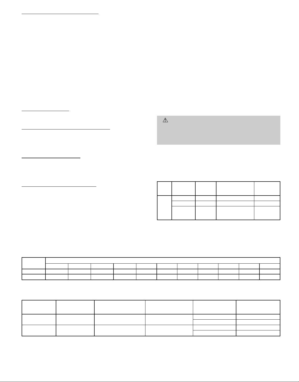
Table6 shows fan rpm at motor pulley settings. Table7 shows
motor performance. Refer to Tables8-11to determine fan speed
settings.
Table 6 — Fan Rpm at Motor Pulley Settings*
UNIT
549B
090 925 905 885 865 845 825 805 785 765 745 725
120 1080 1060 1035 1015 990 970 950 925 905 880 860
*Approximate fan rpm shown.
0
1
⁄
2
11
MOTOR PULLEY TURNS OPEN
1
⁄
2
22
1
⁄
2
33
1
⁄
2
44
1
⁄
2
Table 7 — Indoor-Fan Motor Data
UNIT
549B
090 Three 2.90 2615
120 Three 4.20 3775
LEGEND
Bhp — Brake Horsepower
*Extensive motor and electrical testing on these units ensures that the full horsepower and watts range
of the motors can be utilized with confidence. Using your fan motors up to the ratings shown in this
table will not result in nuisance tripping or premature motor failure. Unit warranty will not be affected.
UNIT
PHASE
MAXIMUM
CONTINUOUS
BHP*
MAXIMUM
OPERATING
WATTS*
UNIT
VOLTAGE
208/230 7.9
460 3.6
208/230 11.1
460 5.0
MAXIMUM
—19—
AMP
DRAW
5
Page 20
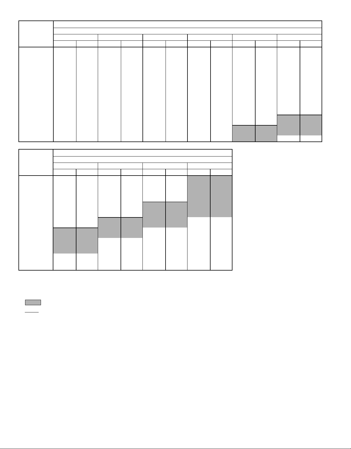
Table 8 — 549B090 Air Delivery — Vertical Discharge Units
BELT DRIVE MOTOR
AIRFLOW
(Cfm)
2250 511 0.52 592 0.74 659 0.95 722 1.19 778 1.43 829 1.68
2300 518 0.55 599 0.77 665 0.98 727 1.22 783 1.47 834 1.72
2400 534 0.61 613 0.84 677 1.06 738 1.30 794 1.55 844 1.81
2500 549 0.67 627 0.90 690 1.14 750 1.38 805 1.64 855 1.91
2550 557 0.71 633 0.94 697 1.18 756 1.42 811 1.69 861 1.96
2600 565 0.74 639 0.97 703 1.22 761 1.46 816 1.74 866 2.01
2700 581 0.81 652 1.04 717 1.31 773 1.55 827 1.83 878 2.12
2800 597 0.89 665 1.12 733 1.40 786 1.66 839 1.93 889 2.23
2900 613 0.97 679 1.20 745 1.50 799 1.76 850 2.04 900 2.34
3000 629 1.06 694 1.29 759 1.59 812 1.88 862 2.15 911 2.46
3100 646 1.15 709 1.39 772 1.70 825 1.99 875 2.28 923 2.58
3200 662 1.25 724 1.50 785 1.80 840 2.11 887 2.41 934 2.71
3300 679 1.35 740 1.61 798 1.91 854 2.24 900 2.54 946 2.85
3400 696 1.46 756 1.73 811 2.02 868 2.37 914 2.69 959 3.00
3500 712 1.57 771 1.85 824 2.14 881 2.50 928 2.84 971 3.16
3600 729 1.69 787 1.98 839 2.21 894 2.64 942 2.99 984 3.22
3700 746 1.85 803 2.12 854 2.42 907 2.78 956 3.15 997 3.49
3750 755 1.89 811 2.20 862 2.49 914 2.85 963 3.23 — —
AIRFLOW
(Cfm)
2250 884 1.97 937 2.33 947 2.66 1022 3.10
2300 885 2.00 939 2.36 979 2.69 1025 3.12
2400 892 2.08 944 2.40 987 2.76 1039 3.20
2500 902 2.18 949 2.48 1002 2.84 1041 3.25
2550 908 2.24 953 2.53 1003 2.87 1045 3.28
2600 913 2.29 957 2.58 1004 2.91 1050 3.31
2700 924 2.40 967 2.70 1010 3.01 1056 3.37
2800 935 2.52 978 2.62 1019 3.13 1061 3.47
2900 946 2.65 989 2.96 1030 3.27 — —
3000 957 2.78 1000 3.09 1040 3.41 — —
3100 968 2.91 1011 3.24 ————
3200 980 3.04 1022 3.38 ————
3300 991 3.18 ——————
3400 1003 3.32 ——————
3500 1014 3.48 ——————
3600 ————————
3700 ————————
3750 ————————
LEGEND
Bhp — Brake Horsepower Input to Fan
NOTES:
1. Boldface indicates a field-supplied drive is required. (See Note 7.)
2. indicates field-supplied motor and drive are required.
3.
4. Maximum continuous bhp is 2.90. Extensive motor and electrical test-
indicates maximum usable bhp of factory-installed motor.
ing on these units ensures that the full range of the motor can be
0.2 0.4 0.6 0.8 1.0 1.2
Rpm Bhp Rpm Bhp Rpm Bhp Rpm Bhp Rpm Bhp Rpm Bhp
BELT DRIVE MOTOR (cont)
External Static Pressure (in. wg)
1.4 1.6 1.8 2.0
Rpm Bhp Rpm Bhp Rpm Bhp Rpm Bhp
External Static Pressure (in. wg)
utilized with confidence. Using your fan motors up to the ratings shown
will not result in nuisance tripping or premature motor failure. Unit
warranty will not be affected.
5. Values include losses for filters, unit casing, and wet coils.
6. Use of a field-supplied motor may affect wire sizing. Contact distributor to verify.
7. Standard motor drive range: 725 to 925 rpm. All other rpms require
field-supplied drive.
8. Interpolation is permissible. Do not extrapolate.
—20—
Page 21
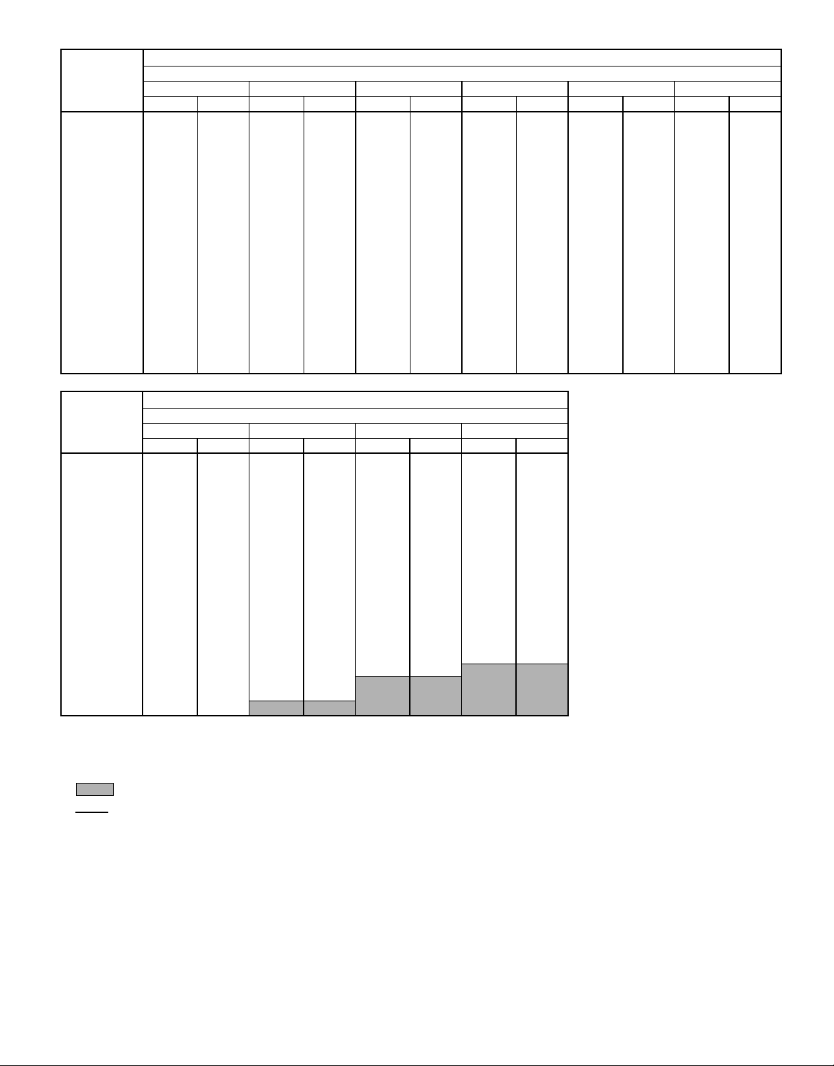
Table 9 — 549B120 Air Delivery — Vertical Discharge Units
BELT DRIVE MOTOR
AIRFLOW
(Cfm)
3000 459 0.46 625 0.85 691 1.01 734 1.10 787 1.30 829 1.50
3100 478 0.57 637 0.90 702 1.08 744 1.16 796 1.36 837 1.56
3200 500 0.62 647 0.97 712 1.16 753 1.23 805 1.43 845 1.63
3300 519 0.69 658 1.03 721 1.23 762 1.30 814 1.50 853 1.71
3400 537 0.77 669 1.10 731 1.30 773 1.38 823 1.57 862 1.78
3500 561 0.86 680 1.17 741 1.37 784 1.47 832 1.65 871 1.86
3600 592 0.98 692 1.24 751 1.45 796 1.57 841 1.72 880 1.95
3700 654 1.12 714 1.31 767 1.50 815 1.67 861 1.85 906 2.08
3800 668 1.20 727 1.40 780 1.60 827 1.77 873 1.95 916 2.18
3900 683 1.28 741 1.49 793 1.70 839 1.88 884 2.05 927 2.28
4000 697 1.37 754 1.59 806 1.80 851 1.99 895 2.16 938 2.38
4100 711 1.46 767 1.69 819 1.90 864 2.10 907 2.28 949 2.49
4200 726 1.56 780 1.80 832 2.01 877 2.22 919 2.41 960 2.60
4300 741 1.66 794 1.91 845 2.12 889 2.35 931 2.54 971 2.72
4400 755 1.77 808 2.03 858 2.24 902 2.48 943 2.68 983 2.86
4500 770 1.89 821 2.15 871 2.37 915 2.61 955 2.82 995 3.01
4600 784 2.00 835 2.27 884 2.49 928 2.75 968 2.96 1006 3.17
4700 799 2.13 849 2.40 897 2.63 941 2.88 981 3.11 1018 3.32
4800 814 2.25 863 2.53 910 2.77 954 3.02 993 3.27 1030 3.48
4900 829 2.39 877 2.67 923 2.92 967 3.17 1006 3.43 1043 3.65
5000 843 2.52 892 2.81 937 3.08 980 3.32 1019 3.60 1055 3.82
AIRFLOW
(Cfm)
3000 886 1.73 943 1.88 988 1.91 995 1.95
3100 892 1.78 947 2.00 995 2.05 1008 2.07
3200 899 1.85 951 2.06 1000 2.17 1021 2.20
3300 907 1.93 959 2.10 1004 2.33 1036 2.36
3400 915 2.01 966 2.17 1009 2.46 1043 2.47
3500 924 2.09 974 2.24 1015 2.51 1054 2.59
3600 933 2.18 983 2.32 1023 2.58 1058 2.70
3700 950 2.27 991 2.47 1030 2.65 1064 2.82
3800 959 2.38 1001 2.58 1040 2.78 1075 2.96
3900 969 2.50 1010 2.70 1049 2.91 1085 3.11
4000 979 2.62 1020 2.83 1059 3.04 1095 3.25
4100 989 2.74 1029 2.96 1068 3.18 1105 3.39
4200 1000 2.86 1039 3.10 1077 3.31 1114 3.54
4300 1011 2.97 1049 3.23 1087 3.46 1124 3.69
4400 1022 3.10 1059 3.37 1097 3.61 1133 3.84
4500 1033 3.23 1070 3.51 1107 3.76 1143 4.00
4600 1044 3.37 1081 3.64 1117 3.92 1152 4.17
4700 1056 3.52 1092 3.78 1127 4.07 1162 4.33
4800 1057 3.69 1103 3.93 1138 4.23 1172 4.50
4900 1079 3.87 1114 4.09 1149 4.37 1182 4.68
5000 1091 4.05 1126 4.25 1160 4.53 1193 4.85
LEGEND
Bhp — Brake Horsepower Input to Fan
NOTES:
1. Boldface indicates a field-supplied drive is required. (See Note 7.)
2. indicates field-supplied motor and drive are required.
3.
4. Maximum continuous bhp is 4.20 with standard motor. Extensive mo-
indicates maximum usable bhp of factory-installed motor.
tor and electrical testing on these units ensures that the full range of
0.2 0.4 0.6 0.8 1.0 1.2
Rpm Bhp Rpm Bhp Rpm Bhp Rpm Bhp Rpm Bhp Rpm Bhp
BELT DRIVE MOTOR (cont)
External Static Pressure (in. wg)
1.4 1.6 1.8 2.0
Rpm Bhp Rpm Bhp Rpm Bhp Rpm Bhp
External Static Pressure (in. wg)
the motor can be utilized with confidence. Using your fan motors up
to the ratings shown will not result in nuisance tripping or premature
motor failure. Unit warranty will not be affected.
5. Values include losses for filters, unit casing, and wet coils.
6. Use of a field-supplied motor may affect wire sizing. Contact distributor to verify.
7. Standard motor drive range: 860 to 1080 rpm. All other rpms require
field-supplied drive.
8. Interpolation is permissible. Do not extrapolate.
—21—
Page 22
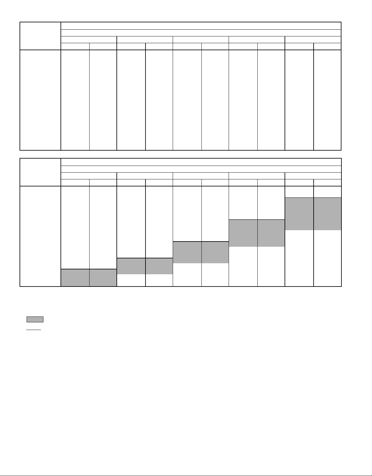
Table 10 — 549B090 Air Delivery — Horizontal Discharge Units
BELT DRIVE MOTOR
AIRFLOW
(Cfm)
2250 465 0.43 554 0.64 630 0.86 695 1.09 757 1.34
2300 471 0.45 559 0.66 635 0.89 699 1.12 760 1.37
2400 482 0.50 569 0.71 645 0.95 708 1.18 768 1.44
2500 494 0.54 581 0.76 654 1.01 717 1.25 776 1.51
2550 501 0.57 587 0.79 659 1.05 722 1.29 780 1.55
2660 507 0.59 592 0.82 663 1.08 727 1.32 784 1.58
2700 520 0.65 604 0.89 672 1.14 737 1.40 793 1.66
2800 533 0.71 615 0.95 683 1.20 747 1.49 802 1.75
2900 546 0.77 626 1.02 693 1.27 756 1.57 813 1.84
3000 559 0.83 637 1.09 704 1.35 765 1.66 823 1.94
3100 572 0.90 648 1.17 715 1.43 775 1.74 832 2.05
3200 585 0.96 660 1.24 727 1.52 785 1.83 841 2.15
3300 598 1.03 671 1.32 739 1.62 795 1.91 851 2.26
3400 610 1.10 682 1.41 750 1.72 806 2.01 860 2.36
3500 623 1.17 694 1.50 761 1.82 817 2.11 870 2.47
3600 636 1.25 707 1.60 772 1.93 828 2.23 880 2.57
3700 649 1.33 720 1.71 783 2.03 840 2.35 890 2.69
3750 655 1.37 727 1.77 789 2.09 846 2.42 896 2.75
AIRFLOW
(Cfm)
2250 810 1.62 850 1.91 873 2.20 883 2.50 895 2.78
2300 816 1.65 859 1.94 888 2.24 903 2.55 911 2.85
2400 824 1.72 872 2.01 909 2.32 931 2.64 935 2.96
2500 832 1.79 882 2.09 925 2.40 955 2.72 972 3.06
2550 836 1.83 887 2.13 931 2.45 964 2.77 986 3.11
2660 839 1.87 891 2.17 936 2.49 973 2.82 999 3.16
2700 846 1.95 898 2.26 946 2.58 987 2.91 1019 3.26
2800 855 2.04 906 2.35 954 2.67 997 3.01 1034 3.36
2900 863 2.13 913 2.44 961 2.77 1006 3.12 — —
3000 872 2.22 921 2.54 969 2.88 1014 3.22 — —
3100 882 2.33 930 2.65 976 2.99 1021 3.34 — —
3200 892 2.45 939 2.76 984 3.10 ————
3300 902 2.57 948 2.88 993 3.21 ————
3400 912 2.69 958 3.01 1002 3.34 ————
3500 921 2.82 968 3.15 ——————
3600 930 2.95 978 3.29 ——————
3700 940 3.07 — ———————
3750 945 3.14 — ———————
LEGEND
Bhp — Brake Horsepower Input to Fan
NOTES:
1. Boldface indicates a field-supplied drive is required. (See Note 7.)
2. indicates field-supplied motor and drive are required.
3.
4. Maximum continuous bhp is 2.90. Extensive motor and electrical test-
indicates maximum usable bhp of factory-installed motor.
ing on these units ensures that the full range of the motor can be
0.2 0.4 0.6 0.8 1.0
Rpm Bhp Rpm Bhp Rpm Bhp Rpm Bhp Rpm Bhp
1.2 1.4 1.6 1.8 2.0
Rpm Bhp Rpm Bhp Rpm Bhp Rpm Bhp Rpm Bhp
External Static Pressure (in. wg)
BELT DRIVE MOTOR (cont)
External Static Pressure (in. wg)
utilized with confidence. Using your fan motors up to the ratings shown
will not result in nuisance tripping or premature motor failure. Unit
warranty will not be affected.
5. Values include losses for filters, unit casing, and wet coils.
6. Use of a field-supplied motor may affect wire sizing. Contact distributor to verify.
7. Standard motor drive range: 725 to 925 rpm. All other rpms require
field-supplied drive.
8. Interpolation is permissible. Do not extrapolate.
—22—
Page 23
Table 11 — 549B120 Air Delivery — Horizontal Discharge Units
BELT DRIVE MOTOR
AIRFLOW
(Cfm)
3000 459 0.35 595 0.74 657 0.88 716 1.05 770 1.24
3100 478 0.46 605 0.79 667 0.94 725 1.10 779 1.30
3200 500 0.57 615 0.85 679 1.01 734 1.16 787 1.36
3300 519 0.62 625 0.90 691 1.08 744 1.23 796 1.43
3400 537 0.69 637 0.97 702 1.16 753 1.30 805 1.50
3500 561 0.77 647 1.03 712 1.23 762 1.38 814 1.57
3600 592 0.86 658 1.10 721 1.30 773 1.47 823 1.65
3700 607 0.97 670 1.18 732 1.37 782 1.56 833 1.73
3800 621 1.05 681 1.25 742 1.45 795 1.66 842 1.82
3900 636 1.13 693 1.32 751 1.53 808 1.76 851 1.92
4000 650 1.21 705 1.40 761 1.61 819 1.86 861 2.02
4100 665 1.30 717 1.48 772 1.71 830 1.96 871 2.13
4200 680 1.39 728 1.57 783 1.81 839 2.05 883 2.25
4300 696 1.49 739 1.66 794 1.91 848 2.14 896 2.38
4400 711 1.60 750 1.75 805 2.02 857 2.24 908 2.51
4500 727 1.70 762 1.85 817 2.12 867 2.35 919 2.63
4600 742 1.82 774 1.96 828 2.23 877 2.46 929 2.75
4700 758 1.94 786 2.07 840 2.34 888 2.59 938 2.87
4800 773 2.06 799 2.18 852 2.46 899 2.72 947 2.98
4900 789 2.19 812 2.30 863 2.57 910 2.86 957 3.11
5000 805 2.32 826 2.43 875 2.70 921 2.99 966 3.24
AIRFLOW
(Cfm)
3000 822 1.44 872 1.69 919 1.88 950 1.70 962 1.82
3100 829 1.50 882 1.73 932 2.00 965 1.80 971 1.95
3200 837 1.56 886 1.78 943 2.06 978 1.91 984 2.07
3300 845 1.63 892 1.85 947 2.10 988 2.05 995 2.20
3400 853 1.71 899 1.93 951 2.17 995 2.17 1008 2.32
3500 862 1.78 907 2.01 959 2.24 1000 2.33 1021 2.47
3600 871 1.86 915 2.09 965 2.32 1005 2.46 1036 2.59
3700 879 1.95 927 2.17 973 2.38 1013 2.57 1046 2.73
3800 889 2.03 934 2.26 980 2.48 1022 2.69 1058 2.87
3900 898 2.12 942 2.36 987 2.59 1030 2.81 1068 3.01
4000 908 2.21 950 2.46 994 2.70 1037 2.92 1077 3.14
4100 917 2.32 960 2.55 1001 2.81 1045 3.04 1085 3.21
4200 925 2.44 969 2.65 1009 2.92 1051 3.17 1092 3.40
4300 935 2.56 979 2.77 1018 3.03 1058 3.29 1100 3.53
4400 945 2.68 988 2.89 1028 3.14 1066 3.41 1106 3.67
4500 955 2.82 996 3.02 1037 3.25 1074 3.54 1113 3.81
4600 967 2.96 1005 3.16 1046 3.38 1084 3.66 1121 3.95
4700 980 3.11 1015 3.30 1056 3.52 1093 3.79 1129 4.09
4800 992 3.26 1025 3.45 1064 3.67 1103 3.92 1137 4.22
4900 1003 3.41 1036 3.61 1073 3.83 1112 4.07 1147 4.36
5000 1014 3.56 1049 3.79 1083 4.00 1121 4.23 1157 4.50
LEGEND
Bhp — Brake Horsepower Input to Fan
NOTES:
1. Boldface indicates a field-supplied drive is required. (See Note 7.)
2. indicates field-supplied motor and drive are required.
3.
4. Maximum continuous bhp is 4.20. Extensive motor and electrical test-
indicates maximum usable bhp of factory-installed motor.
ing on these units ensures that the full range of the motor can be
0.2 0.4 0.6 0.8 1.0
Rpm Bhp Rpm Bhp Rpm Bhp Rpm Bhp Rpm Bhp
1.2 1.4 1.6 1.8 2.0
Rpm Bhp Rpm Bhp Rpm Bhp Rpm Bhp Rpm Bhp
External Static Pressure (in. wg)
BELT DRIVE MOTOR (cont)
External Static Pressure (in. wg)
utilized with confidence. Using your fan motors up to the ratings shown
will not result in nuisance tripping or premature motor failure. Unit
warranty will not be affected.
5. Values include losses for filters, unit casing, and wet coils.
6. Use of a field-supplied motor may affect wire sizing. Contact distributor to verify.
7. Standard motor drive range: 860 to 1080 rpm. All other rpms require
field-supplied drive.
8. Interpolation is permissible. Do not extrapolate.
—23—
Page 24
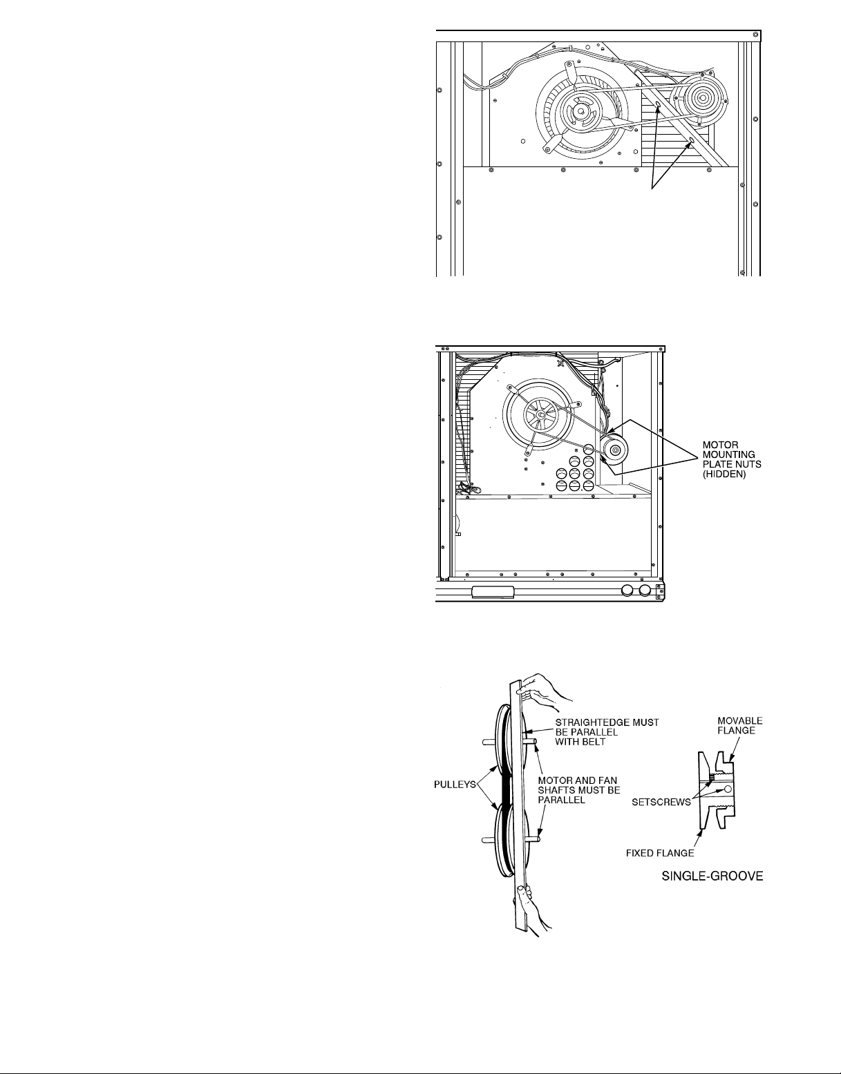
A. Belt Drive Motors
To change fan speeds:
1. Shut off unit power supply.
2. Loosen belt by loosening fan motor mounting nuts. See
Fig. 30 and 31.
3. Loosen movable pulley flange setscrew (see Fig. 32).
4. Screw movable flange toward fixed flange to increase speed
and away from fixed flange to decrease speed. Increasing fan speed increases load on motor.Do not exceed maximum speed specified in Table 1.
5. Set movable flange at nearest keyway of pulley hub and
tighten setscrew.(See Table 1 for speed change foreach
full turn of pulley flange.)
To align fan and motor pulleys:
1. Loosen fan pulley setscrews.
2. Slide fan pulley along fan shaft.
3. Make angular alignment by loosening motor from
mounting plate.
To adjust belt tension:
1. Loosen fan motor mounting nuts.
2. Size 090 — Slide motor mounting plate away from fan
1
scroll for proper belt tension (
⁄2-in. deflection with one
finger) and tighten mounting nuts (see Fig. 30).
Size 120 — Slide motor mounting plate downward to
tighten belt tension. Secure motor mounting plate nuts.
See Fig. 31.
3. Adjust bolt and nut on mounting plate to secure motor
in fixed position.
MOTOR MOUNTING
PLATE NUTS
Fig. 30 — Typical Belt-Drive Motor Mounting
for Size 090
B. Ventilation Sequence
If unit is equipped with economizer or two-position damper,
the damper will open to the minimum position wheneverthe
indoor fan runs.
Whenever the indoor fan is energized (during heating, cooling, or continuous fan), 24-v power is on terminal R1 on
the economizer control board or terminal no. 1 on R1 on the
two-position damper wiring harness. The damper motor will
be energized with 24-vdc power and damper will drive open
until SW3 on the damper is deactivated. The damper motor
will stop and damper will remain in the minimum ventilation position until the indoor fan is shut off. When the indoor
fan is shut off, the damper motor is again energized and the
damper runs closed until SW2 is activated and the damper
motor turns off.
When unit is equipped with an economizer, additional outdoor air can be brought in through the damper to provide cooling. If the unit calls for cooling and the outdoor-air temperature is below the OAT setting or the outdoor-air enthalpy is
below the EC setting, the damper motor starts. The damper
drives open until SAT (supply-air thermostat) reads less than
57 F or until fully open and SW2 is activated. When SW1 is
deactivated, the damper motor stops. When the cooling load
is satisfied, or outdoor air is no longer below the OAT or EC
setting, the damper returns to the minimum position.
If the SAT (located on the indoor-fan housing) senses a mixedair temperature less than 52 F, the damper closes until the
mixed-air temperature is above 50 F.
Fig. 31 — Typical Belt-Drive Motor Mounting
for Size 120
Fig. 32 — Indoor-Fan Pulley Adjustment
—24—
Page 25
CARE AND MAINTENANCE
To ensure continuing high performance, and to minimize the
possibility of premature equipment failure, periodic maintenance must be performed on this equipment. This combination heating/cooling unit should be inspected at least once each
year by a qualified service person.
NOTE TO EQUIPMENT OWNER: Consult your local dealer
about the availability of a maintenance contract.
WARNING:
nance on this equipment requires certain expertise, mechanical skills, tools, and equipment. If you do notpossess these, do not attempt to perform any maintenance
on this equipment other than those procedures recommended in the User’sManual. FAILURETO HEED THIS
WARNING COULD RESULT IN SERIOUS PERSONAL
INJURY AND POSSIBLE DAMAGE TO THIS
EQUIPMENT.
The minimum maintenance requirements for this equipment
are as follows:
1. Inspect air filters each month. Clean or replace when
necessary.
2. Inspect cooling coil, drain pan, and condensate drain each
cooling season for cleanliness. Clean when necessary.
3. Inspect blower motor and wheel each heating and
cooling season. Clean and lubricate (if required) when
necessary.
4. Check electrical connections for tightness and controls
for proper operation each heating and cooling season.
Service when necessary.
5. Check and inspect heating section before each heating
season.
6. Check and clean optional manual outdoor-air damper or
economizer screen, if applicable.
WARNING:
sult in serious personal injury:
1. Turn off electrical power to the unit before per-
forming any maintenance or service on the unit.
2. Use extreme caution when removing panels and
parts. As with any mechanical equipment, personal injury can result from sharp edges, etc.
3. Never place anything combustible either on, or in
contact with, the unit.
4. Should overheating occur, shut off the electrical
supply.
I. AIR FILTER
CAUTION:
able air filter in the return-air duct system.Always replace the filter with the same dimensional size and type
as originally installed. See Table1 for recommended filter sizes.
Inspect air filters at least once each month and replace
(throwaway-type) or clean (cleanable-type) at least twice during each heating and cooling season and whenever the filters
become clogged with dust and lint.
Replace filters with the same dimensional size and type as
originally provided when necessary.
The ability to properly perform mainte-
Failure to follow these warnings could re-
Never operate the unit without a suit-
SERVICE
CAUTION:
cal power to unit to avoid shock hazard or injury from
rotating parts.
I. CLEANING
Inspect unit interior at the beginning of each heating and cooling season and as operating conditions require.
A. Indoor Coil
1. Turn unit power off. Remove filter access panel and indoor coil access panel.
2. If economizer is installed, remove economizer by disconnecting economizer plug and economizer mounting screws.
Refer to Optional Economizer sections on pages 11 and
14 or Accessory Economizer Installation Instructions for
further details.
3. Slide filters out of unit.
4. Clean coil using a commercial coil cleaner or dishwasher detergent in a pressurized spraycanister. Wash
both sides of coil and flush with clean water. For best
results, backflush toward return-air section to remove
foreign material.
5. Flush condensate pan after completion.
6. Reinstall economizer damper and filters.
7. Reconnect wiring.
8. Replace access panels.
B. Outdoor Coil
Inspect coil monthly. Clean condenser coil annually, and as
required by location and outdoor air conditions.
Clean 2-row coils as follows:
1. Turn off unit power.
2. Remove top panel screws on outdoor end of unit.
3. Remove outdoor coil corner post. See Fig. 33. To hold
top panel open, place coil corner post between top panel
and center post. See Fig. 34.
4. Remove screws securing coil to center post.
5. Remove device holding coil sections together at return
end of outdoor coil. Carefully separate the outer coil
section 3 to 4 in. from the inner coil section (see
Fig. 35).
6. Use a water hose or other suitable equipment to flush
down between the 2 coil sections to remove dirt and
debris. Clean the outer surfaces with a stiff brush in
the normal manner.
7. Secure inner and outer coil rows together with a fieldsupplier fastener.
8. Reposition the outer coil section and remove the coil
corner post from between the top panel and center post.
9. Install the coil corner post and coil center post.
10. Replace all screws.
C. Condensate Drain
Check and clean each year at start of cooling season. In winter, keep drain dry or protect against freeze-up.
D. Filters
Clean or replace at start of each heating and cooling season,
or more often if operating conditions require it. Replacement
filters must be same dimensions as original filters.
E. Outdoor-Air Inlet Screens
Clean screens with steam or hotwater and a milddetergent.
Do not use disposable filters in place of screens.
When servicing unit, shut off all electri-
—25—
Page 26
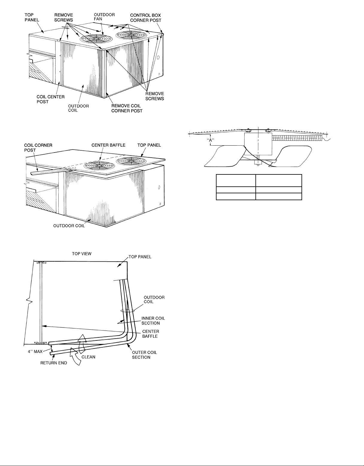
Fig. 33 — Cleaning Outdoor Coil
B. Fan-Motor Bearings
Fan-motor bearings are of the permanently lubricated type.
No further lubrication is required. No lubrication of outdooror indoor-fan motors is required.
III. OUTDOOR-FAN ADJUSTMENT (Fig. 36)
1. Shut off unit power supply.
2. Remove outdoor-fan assembly (grille, motor,and fan) by
removing screws and flipping assembly onto unit top cover.
Loosen fan hub setscrews.
3. Adjust fan height as shown in Fig. 36.
4. Tighten setscrews.
5. Replace outdoor-fan assembly.
IV. ECONOMIZER ADJUSTMENT
Refer to Optional Economizer sections on pages 11 and 14.
Fig. 34 — Propping Up Top Panel
Fig. 35 — Separating Coil Sections
II. LUBRICATION
A. Compressors
Each compressor is charged withcorrect amount of oil at the
factory.
UNIT
VOLTAGE
208/230 V 2.75
460 V 3.50
FAN HEIGHT
‘‘A’’ (in.)
Fig. 36 — Outdoor Fan Adjustment
V. REFRIGERANT CHARGE
Amount of refrigerant charge is listed on unit nameplate (also
refer to Table 1). Refer to GTAC2-5 Charging, Recovery, Recycling, and Reclamation training manual and the following
procedures. Unit panels must be in place when unit is operating during charging procedure.
This unit uses a fixed-orifice refrigerant metering device
located in the coil header. There is one orifice in eachcoil circuit. The size of the orifice is stamped on the outside of the
tube where the orifice is located. Orifices are factory selected
for optimum performance and are not designed to be changed
in the field. To determine if an orifice is plugged, disconnect
power to the indoor-fan motor and start the unit in cooling
mode. Observe the coil for an uneven frost pattern, indicating a plugged orifice.
A. No Charge
Use standard evacuating techniques. After evacuating system, weigh in the specified amount of refrigerant. (Refer to
Table 1.)
B. Low Charge Cooling
Using Cooling Charging Chart, Fig. 37 and 38 vary refrigerant until the conditions of the appropriate chart are met. Note
the charging charts are different from the type normally used.
Charts are based on charging the units to the correct superheat for the various operating conditions. Accurate pressure
gage and temperature sensing device are required. Connect
the pressure gage to the service port on the suction line. Mount
—26—
Page 27
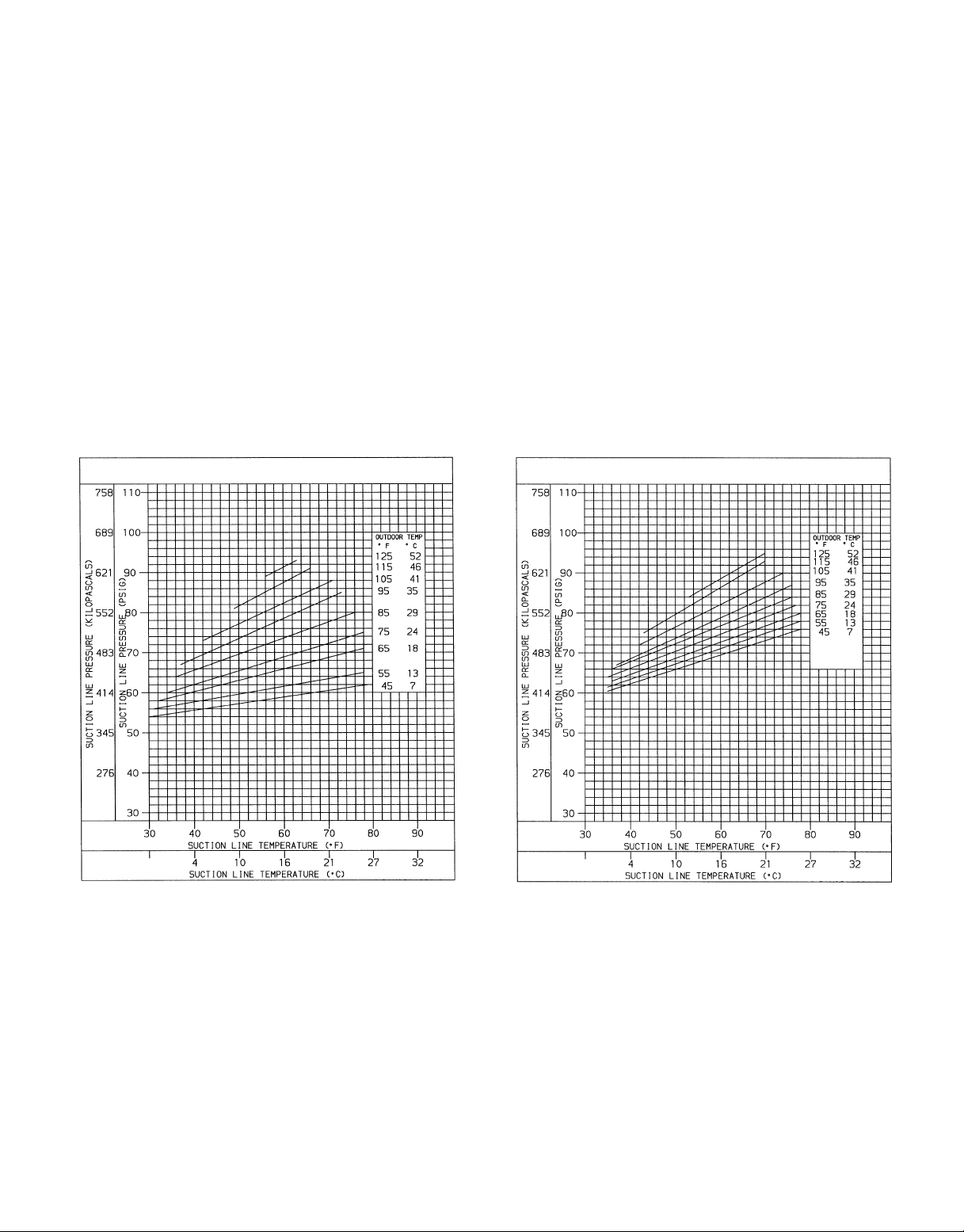
the temperature sensing device on the suction line and insulate it so that outdoor ambient temperature does not affect
the reading. Indoor air cfm must be within the normal operating range of the unit.
C. To Use Cooling Charging Chart
Take the outdoor ambient temperature and read the suction
pressure gage. Refer to appropriate chart to determine what
suction temperature should be. If suction temperature is high,
add refrigerant. If suction temperature is low, carefully recover some of the charge. Recheck the suction pressure as
charge is adjusted.
EXAMPLE: (Fig. 37) Circuit No. 1
Outdoor Temperature ...........................85F
Suction Pressure .............................70psig
Suction Temperature should be ...................51F
(Suction Temperature may vary±5F.)
D. Refrigerant Leaks
Proceed as follows to repair a refrigerant leak and to charge
the unit:
1. Locate leak and ensure that refrigerant system pressure has been relieved.
2. Repair leak following accepted practices.
NOTE: Install a filter drier whenever the system has been
opened for repair.
3. Add a small charge of R-22 refrigerant vapor to system
and leak-test unit.
4. Evacuate refrigerant system if additional leaks are not
found.
5. Charge unit with R-22 refrigerant, using a volumetriccharging cylinder or accurate scale. Refer to unit rating
plate for required charge. Be sure to add extra refrigerant to compensate for internal volume of filter drier.
VI. REPLACEMENT PARTS
A complete list of replacement parts may be obtained from
your distributor upon request.
Fig. 37 — Cooling Charging Chart, 549B090
Fig. 38 — Cooling Charging Chart, 549B120
—27—
Page 28
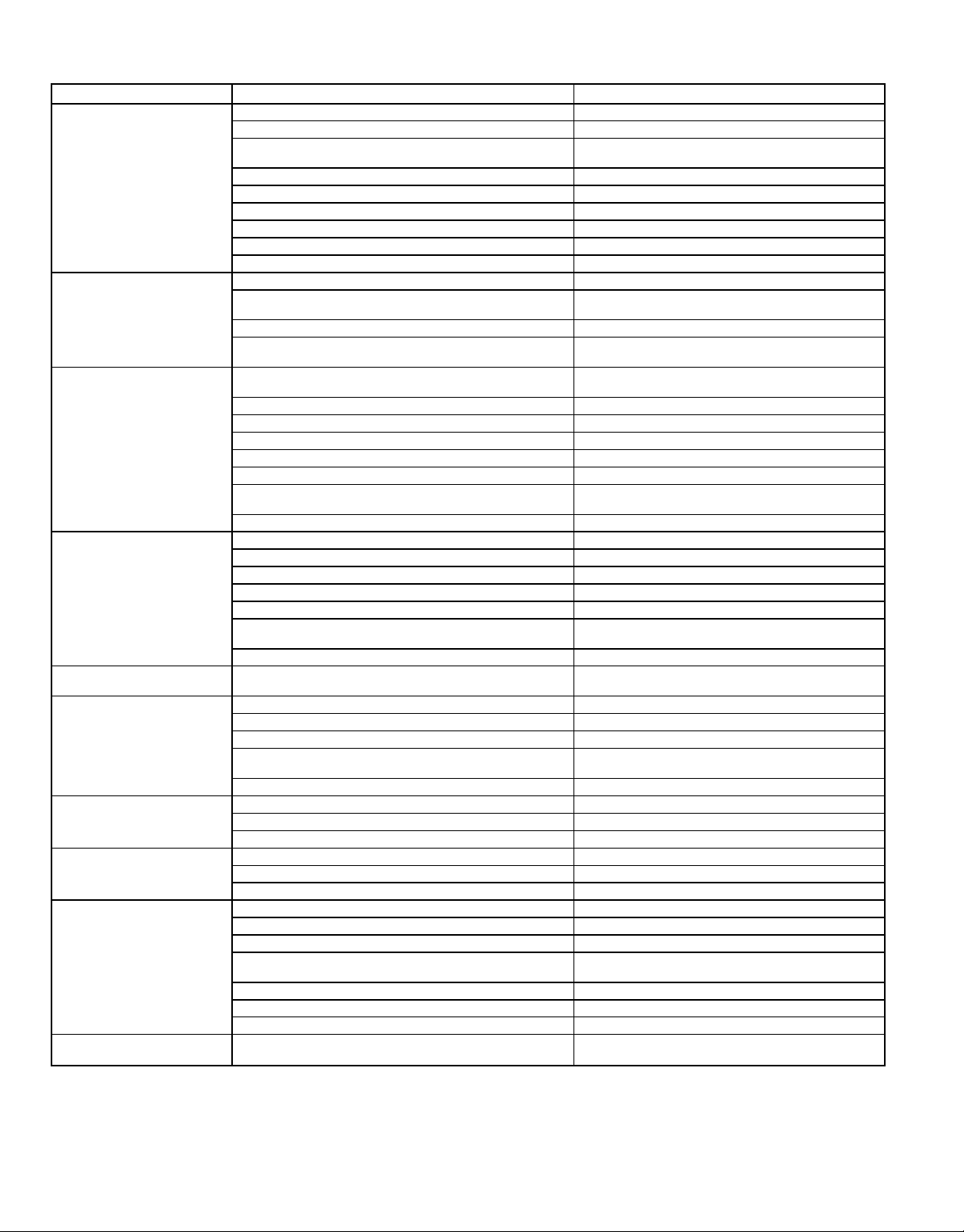
TROUBLESHOOTING
Table 12 — Heating and Cooling Troubleshooting
PROBLEM CAUSE REMEDY
Compressor(s) and
outdoor fan(s)
will not start.
Compressor(s) will not
start but outdoor fan(s)
runs.
Compressor cycles
(other than normally
satisfying thermostat).
Compressor operates
continuously.
Scroll compressor
makes excessive noise.
Excessive head pressure. Dirty air filter. Replace filter.
Head pressure too low. Low refrigerant charge. Check for leaks, repair, and recharge.
Excessive suction
pressure.
Suction pressure too low. Dirty air filter (cooling) or dirty outdoor coil (heating). Replace filter or clean coil.
Compressor no. 2
will not run.
Power failure. Call power company.
Fuse blown or circuit breaker tripped. Replace fuse or reset circuit breaker.
Defective thermostat, contactor, transformer, or control
relay.
Insufficient line voltage. Determine cause and correct.
Incorrect or faulty wiring. Check wiring diagram and rewire correctly.
Thermostat setting too high. Lower thermostat setting below room temperature.
High-pressure switch tripped. See problem ‘‘Excessive head pressure.’’
Low-pressure switch tripped. Check for leaks, repair, and recharge.
Freeze-up protection thermostat tripped. See problem ‘‘Suction pressure too low.’’
Faulty wiring or loose connections in compressor circuit. Check wiring and repair or replace.
Compressor motor burned out, seized, or internal
overload open.
Defective overload. Determine cause and replace.
One leg of 3-phase power dead. Replace fuse or reset circuit breaker.
Refrigerant overcharge or undercharge. Recover refrigerant, evacuate system, and
Defective compressor. Replace and determine cause.
Insufficient line voltage. Determine cause and correct.
Blocked outdoor coil or dirty air filter. Determine cause and correct.
Defective overload. Determine cause and replace.
Defective thermostat. Replace thermostat.
Faulty outdoor-fan motor (cooling) or indoor-fan motor
(heating).
Restriction in refrigerant system. Locate restriction and remove.
Dirty air filter. Replace filter.
Unit undersized for load. Decrease load or increase unit size.
Thermostat set too low. Reset thermostat.
Low refrigerant charge. Locate leak, repair, and recharge.
Leaking valves in compressor. Replace compressor.
Air in system. Recover refrigerant, evacuate system, and
Outdoor coil dirty or restricted. Clean coil or remove restriction.
Compressor rotating in the wrong direction. Reverse the 3-phase power leads as described in
Dirty outdoor coil. Clean coil.
Refrigerant overcharged. Remove excess refrigerant.
Air in system. Recover refrigerant, evacuate system, and
Condensing air restricted or air short-cycling. Determine cause and correct.
Compressor valves leaking. Replace compressor.
Restriction in liquid tube. Remove restriction.
High heat load. Check for source and eliminate.
Compressor valves leaking. Replace compressor.
Refrigerant overcharged. Recover excess refrigerant.
Low refrigerant charge. Check for leaks, repair, and recharge.
Metering device or low side restricted. Remove source of restriction.
Insufficient indoor airflow (cooling mode). Increase air quantity. Check filter and replace if
Temperature too low in conditioned area. Reset thermostat.
Field-installed filter drier restricted. Replace.
Outdoor ambient temperature below 25 F (cooling). Install low-ambient kit.
Unit in economizer mode. Proper operation; no remedy necessary.
Replace component.
Determine cause. Replace compressor.
Determine cause.
recharge to nameplate.
Replace.
recharge.
Start-Up, page 17.
recharge.
necessary.
—28—
Page 29
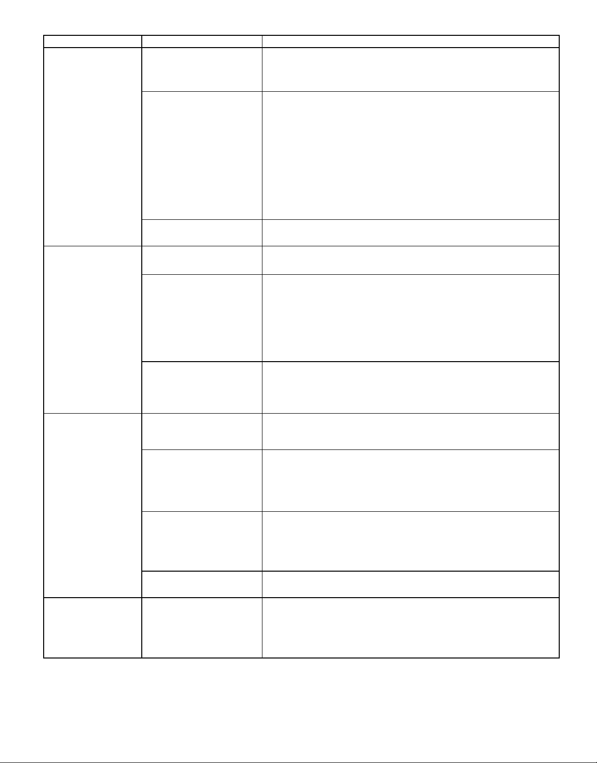
Table 13 — Varislide™ Economizer Troubleshooting
PROBLEM CAUSE REMEDY
Damper does not
open.
Economizer operation
limited to minimum
position.
Damper does not
close.
Economizer damper
does not close on
power loss.
Indoor fan is off. 1. Check to ensure that 24 vac is present at terminal C1 on the IFC or that
No power to economizer
motor.
Economizer motor failure. If the indoor fan and economizer motor are energized, verify that there is a
OAT or EC set too high. 1. Set at correct temperature (3 F below indoor space temperature).
Economizer control board
incorrectly wired or not
functioning.
Incorrect SAT wiring or inoperative SAT.
Incorrect economizer
wiring.
Incorrect damper actuator
wiring or inoperative economizer circuit board.
Incorrect SAT wiring or inoperative SAT.
Economizer motor failure. If economizer control board and SAT are functioning properly, verify that there is
Insufficient battery power, inoperative economizer control
board.
24 vac is present at the IFO terminal. Check whether 24 vac is present at
PL6-1 (red wire) and/or PL6-3 (black wire). If 24 vac is not present, check
wiring (see unit label diagram).
2. Check proper thermostat connection to G on the connection board.
1. Check that SW3 is properly making contact with the damper blade. Check
that SW1 is in the NC (normally closed) position.
2. Check diode D18. If diode is not functioning properly, replace economizer
control board.
3. Confirm that the economizer control board is grounded properly at PL6-4
(brown wire) and at brown terminal of the economizer control board (brown
wire). The economizer motor must also be grounded properly at the negative
motor terminal (brown wire).
4. Verify SW1 and SW3 are working and wired properly (see unit label
diagram).
5. Check for 24 vac input at both PL6-1 (red wire) and PL6-3 (black wire). If
24 vac not present, check unit wiring (see unit label diagram). If 24 vac is
found in both places, check for 24 vac at the yellow terminal of the economizer control board (yellow wire). If 24 vac power is not present, replace
the economizer control board.
minimum of 18 vdc at the positive motor terminal. If the motor is not operating,
replace the motor.
2. Check OAT or EC by setting above outdoor temperature or humidity level.
If the OAT or EC switches do not close, replace OAT or EC.
1. Perform the following tests when OAT or EC is closed, Y1 is called for, and
damper is at minimum position. Confirm 24 vac on gray terminal of the
economizer control board (gray wire). If 24 vac is not present, check wiring
(see unit label diagram).
2. Verify that SW1 and SW3 are wired correctly and working properly (see unit
label diagram).
3. Check to ensure that 24 vac exists at PL6-2 (blue wire). If 24 vac is not
present, check wiring (see unit wiring label diagram).
4. Check 24 vac output at PL6-10 (white wire). If 24 vac is not present, replace
economizer control board.
1. After verifying that the OAT and EC settings and the economizer control
board wiring are correct, check to ensure that the 24 vac terminal of the SAT
has 24 vac (white wire). If OAT, EC, and control board are functioning and
wired properly and no 24 vac exists, check wiring (see unit label diagram).
2. If supply-air temperature is greater than 57 F, 24 vac should be found at terminal T2 on the SAT (pink wire). If 24 vac is not present, replace SAT.
1. Verify that SW2 and SW4 are wired and working properly (see unit label
diagram).
2. Check diode D19. If diode is not functioning properly, replace economizer
control board.
1. After verifying that the wiring is correct, modulate the damper to the minimum position. Remove the calls for G.
2. If the damper does not move, check for 24 vac at PL6-1 (red wire). If 24 vac
is not present, check wiring (see unit label diagram).
3. If damper still does not move, check for 24 vac at blue terminal of economizer control board (blue wire). If 24 vac is not present, replace the economizer control board.
1. After verifying that the wiring is correct and the economizer control board is
functioning properly, place the OAT or EC switch in the closed position.
Place a call for Y1 and open the damper to the fully open position. Confirm
that the 24 vac terminal of the SAT has 24 vac (white wire). If 24 vac is not
present, check wiring (see unit label diagram).
2. If supply-air temperature is less than 52 F, 24 vac should be found at terminal T1 on the SAT (violet wire). If 24 vac not found, replace SAT.
a minimum of 18 vdc at the positive motor terminal. If a minimum of 18 vdc is
present and the motor is still not operating, replace the motor.
1. Check voltage potential across batteries. If lower than 14 vdc, replace closeon-power-loss power supply (9-v alkaline batteries). Check this emergency
power supply on a regular basis or whenever the filters are changed.
2. If the close-on-power-loss and economizer control board are functioning
properly, check for 14 vdc or higher at the blue terminal of the economizer
control board (blue wire) when power is disconnected from unit. If 14 vdc is
not present, replace the control board.
LEGEND
C1 — Common Power OAT — Outdoor-Air Thermostat
EC — Enthalpy Control PL — Plug
IFC — Indoor Fan Contactor SAT — Supply-Air Thermostat
IFO — Indoor Fan On SW — Economizer Position Switch
—29—
Page 30
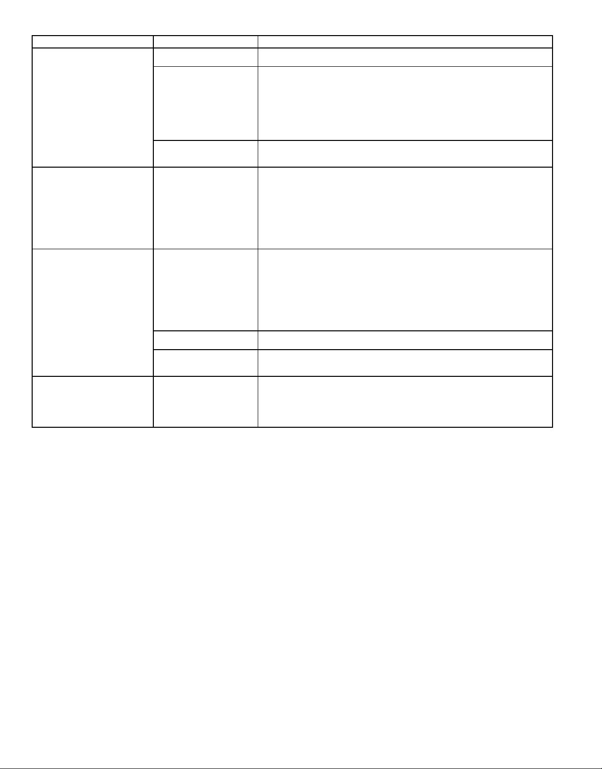
Table 14 — PARABLADE Economizer Troubleshooting
PROBLEM CAUSE REMEDY
Damper does not open. Indoor fan not on. Check wiring between G on connection board and indoor fan
No power to economizer
motor.
Economizer motor
failure.
Economizer operation limited
to minimum position.
Economizer control module failure.
Damper does not close. No power to economizer. 1. Disconnect power at TR and TR1. Disconnect jumper across P and P1.
Spring return failure. If power to unit is off and damper does not close, check for a bound linkage. If
Economizer motor
failure.
Damper does not open
or close according
to enthalpy readings.
Sensor incorrectly wired or
bad.
LEGEND
LED — Light-Emitting Diode
contactor.
1. Disconnect power at TR and TR1. Disconnect jumper across P and P1.
2. Connect jumper across TR and 1.
3. Connect jumper across T1 and T.
4. If connected, remove enthalpy sensor from terminals S
5. Apply power (24 vac) to terminals TR and TR1. The LED should be off and
the damper should be in the closed position.
6. Disconnect the factory-installed 620 ohm resistor from terminals S
The LED should light up and the motor should drive towards open. If this
does not happen, replace the economizer control module.
If the indoor fan and economizer motor are energized, verify that there is a
minimum of 24 vac at terminals TR and TR1. If the motor is not operating, replace the motor.
1. To simulate high or low enthalpy, reconnect the factory-installed 620 ohm
resistor across terminals S
2. Connect 1.2 Kohm checkout resistor across terminals SOand 1. Turn the
enthalpy set point to ‘‘A.’’ The LED should turn on, indicating low enthalpy.
The motor should drive towards open. If LED does not light, replace module.
If motor does not drive open, check motor operation.
3. Turn the enthalpy set point to ‘‘D.’’ The LED should turn off, indicating high
enthalpy. The motor should drive towards closed. If these actions do not occur, replace module.
4. Disconnect 1.2 Kohm checkout resistor before resuming operation.
2. Connect jumper across TR and 1.
3. Connect jumper across T1 and T.
4. If connected, remove enthalpy sensor from terminals S
installed 620 ohm resistor should be connected to terminals SRand 1.
5. Apply power (24 vac) to terminals TR and TR1. The LED should be off and
the damper should be in the closed position.
6. Disconnect the factory-installed 620 ohm resistor from terminals S
The LED should light up and the motor should drive towards open. If this
does not happen, replace the economizer control module.
and 1.
R
and 1.
O
and 1. Factory-
O
linkage is not bound, then internal spring may be broken. Replace actuator.
If the economizer control module is functioning properly, verify that there is a
minimum of 24 vac at terminals TR and TR1. If the motor is not operating, replace the motor.
To verify sensor operation, reconnect the 1 lead of the outdoor enthalpy sensor
to the 1 terminal of the economizer control module. Connect a DC milliammeter
between terminals SOof the economizer control module and terminal S of the
enthalpy sensor. The milliammeter should indicate between 3 and 25 mA if the
sensor is operating properly. If the milliammeter indicates 0, the sensor may be
wired backwards. If any other readings are shown, replace the sensor.
and 1.
R
and 1.
R
Copyright 1995 Carrier Corporation CATALOG NO. BDP-3354-901
Page 31

Page 32
I. PRELIMINARY INFORMATION
START-UP CHECKLIST
(Remove and Store in Job File)
MODEL NO.:
DATE:
II. PRE-START-UP (insert checkmark in box as each item is completed)
SERIAL NO.:
TECHNICIAN:
M REMOVE ALL SHIPPING HOLDDOWN BOLTSAND BRACKETS PER INSTALLATION INSTRUCTIONS
M VERIFY THAT CONDENSATE CONNECTION IS INSTALLED AS SHOWN IN THE
INSTALLATION INSTRUCTIONS
M CHECK ALL ELECTRICAL CONNECTIONS AND TERMINALS FOR TIGHTNESS
M CHECK THAT INDOOR AIR FILTERS ARE CLEAN AND IN PLACE
M VERIFY THAT UNIT INSTALLATION IS LEVEL WITHIN TOLERANCES LISTED IN THE
INSTALLATION INSTRUCTIONS
M CHECK FAN WHEEL AND PROPELLER(S) FOR LOCATION IN HOUSING/ORIFICE AND SETSCREW
TIGHTNESS
M CHECK PULLEY ALIGNMENT AND BELT TENSION; REFER TO INSTALLATION INSTRUCTIONS
III. START-UP
ELECTRICAL
SUPPLY VOLTAGE L1-L2
L2-L3 L3-L1
CIRCUIT NO. 1 COMPRESSOR AMPS L1 L2 L3
CIRCUIT NO. 2 COMPRESSOR AMPS L1 L2 L3
INDOOR FAN AMPS L1 L2 L3
CUT ALONG DOTTED LINE
TEMPERATURES
OUTDOOR-AIR TEMPERATURE
RETURN-AIR TEMPERATURE
DB
DB WB
COOLING SUPPLY AIR
PRESSURES
CIRCUIT NO. 1 CIRCUIT NO. 2
REFRIGERANT SUCTION
REFRIGERANT DISCHARGE
PSIG PSIG
PSIG PSIG
M VERIFY REFRIGERANT CHARGE USING COOLING CHARGING CHARTS.
M VERIFY SCROLL COMPRESSOR IS ROTATING IN CORRECT DIRECTION.
Copyright 1995 Carrier Corporation CATALOG NO. BDP-3354-901
----------------------------------------------------------------------------------------
 Loading...