

Bryant 549B Series Installation, Start-up And Service Instructions Manual
installation, start-up
and service instructions
SINGLE PACKAGE ROOFTOP
HIGH-EFFICIENCY HEAT PUMP UNITS
IMPORTANT — READ BEFORE INSTALLING
1. Read and become familiar with these installation instructions before installing this unit (Fig. 1).
2. Be sure the installation conforms to all applicable local
and national codes.
3. These instructionscontainimportant information for the
proper maintenance and repair of this equipment.
Retain these instructions for future use.
549B
Sizes 090,120
71⁄2and 10 Tons
Cancels: New II 549B-90-1
7/15/95
CONTENTS
Page
SAFETY CONSIDERATIONS ........................1
INSTALLATION .................................1-16
I. Locate the Unit .............................3
II. Unit Duct Connections ......................3
III. Rig and Place Unit ..........................3
IV. Field Connections ..........................6
PRE-START-UP ................................16,17
START-UP ....................................17-24
I. Compressor Rotation .......................17
II. Heating Section Start-Up and Adjustments
For Units With Accessory Electric Heat .......17
III. Cooling Section Start-Up and Adjustments ....18
IV. Indoor Airflow and Airflow Adjustments .......19
CARE AND MAINTENANCE .......................25
I. Air Filter ..................................25
SERVICE .....................................25-27
I. Cleaning .................................25
II. Lubrication ...............................26
III. Outdoor-Fan Adjustment ....................26
IV. Economizer Adjustment ....................26
V. Refrigerant Charge .........................26
VI. Replacement Parts .........................27
TROUBLESHOOTING ...........................28-30
START-UP CHECKLIST ..........................CL-1
Fig.1—Typical Unit
WARNING:
nance operations on unit, turn off main power switch
to unit. Electrical shock could cause personal injury.
1. The power supply (volts, hertz, and phase) must correspond to that specified on unit rating plate.
2. The electrical supply provided by the utility must be sufficient to handle unit load.
3. Refer to Locate the Unit section on page 3 and Fig. 2 for
locations of electrical inlets, condensate drain, duct connections, and required clearances before setting unit in
place.
4. This installation must conform with local building codes
and with NEC (National Electrical Code) or NFPA
(National Fire Protection Association) 54 TIA-54-1.
Refer to provincial and local plumbing or wastewater codes
and other applicable local codes.
5. Approved for outdoor installation on wood flooring or on
class A, B, or C roof covering materials.
Before performing service or mainte-
SAFETY CONSIDERATIONS
Recognize safety information. This is the safety-alert symbol
( ). When you see this symbol on the unit and in instructions or manuals, be alert to the potential for personal
injury.
Understand the signal words — DANGER, WARNING, and
CAUTION. These words are used with the safety-alert symbol. Danger identifies the most serious hazards which will
result in severe personal injury or death. Warning indicates
a situation that could result in personal injury. Caution is
used to identify unsafe practices which would result in minor
personal injury or product and property damage.
INSTALLATION
Unit is shipped in the vertical airflow configuration (see
Fig. 1). To convert to horizontal discharge, remove side duct
opening covers. Using the same screws, install covers with
insulation-side down (facing outside) on the unit over vertical duct openings. Seals around duct openings must
be tight.
All units can be connected into existing duct systems that are
properly sized and designed to handle an airflow of 300 to
500 cfm per each 12,000 Btuh of rated cooling capacity.
UNIT
549B
STANDARD
UNIT
WEIGHT
CORNER
WEIGHT
(A)
CORNER
WEIGHT
(B)
CORNER
WEIGHT
(C)
CORNER
WEIGHT
(D)
Lb Kg Lb Kg Lb Kg Lb Kg Lb Kg ft-in. mm ft-in. mm ft-in. mm
090 870 395 195 90 183 83 237 108 252 114 28-0
120 1000 454 231 105 214 97 269 122 286 130 28-10
NOTES:
CONNECTION SIZES
3
A 1
B 2
C 1
D
E
⁄89 Dia. [35] Field Power Supply Hole
1
⁄29 Dia. [64] Power Supply Knock-Out
3
⁄49 Dia. [44] Charging Port Hole
7
⁄89 Dia. [22] Field Control Wiring Hole
3
⁄49-14 NPT Condensate Drain
F 29 Dia. [51] Power Supply Knock-Out
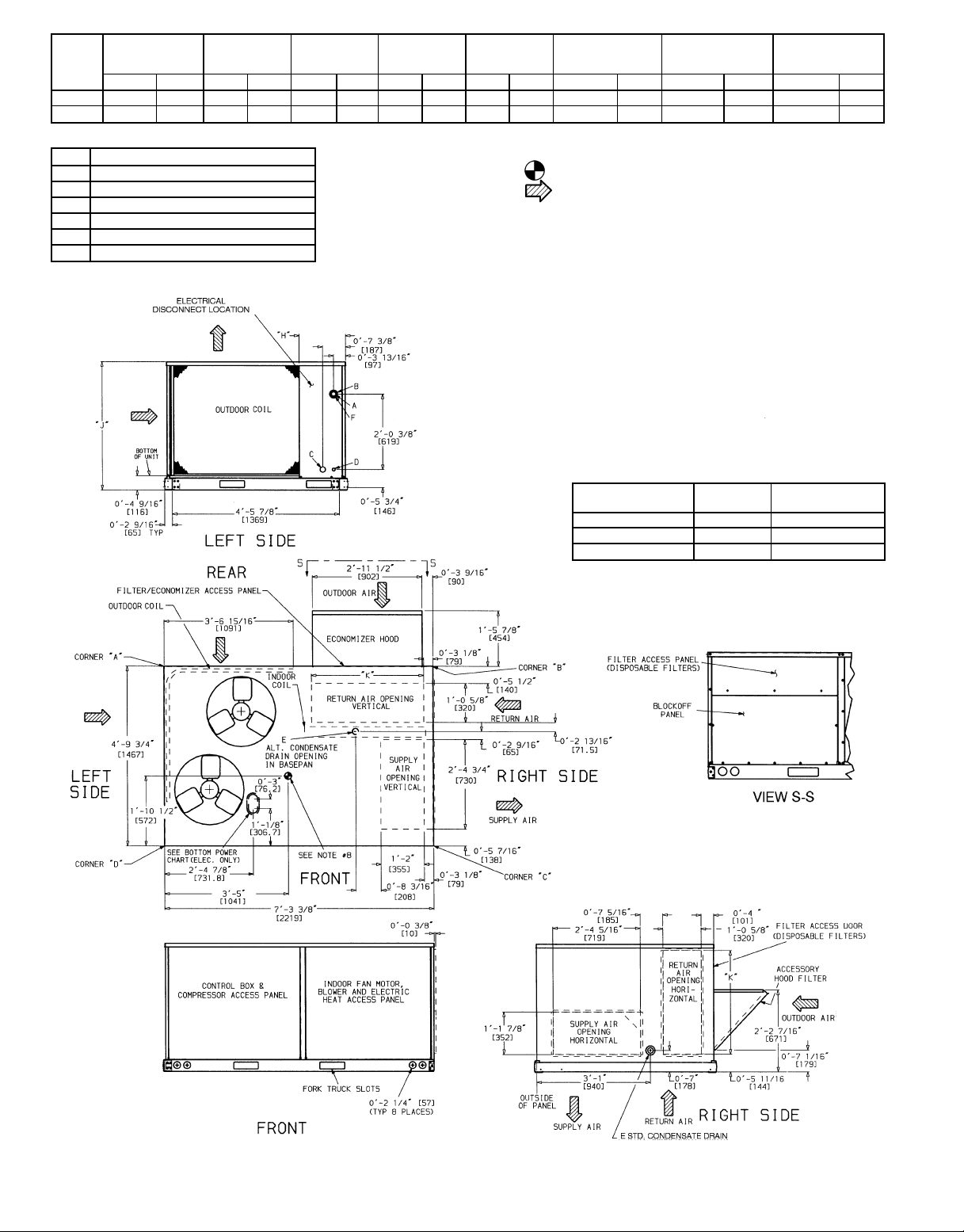
1. Dimensions in [ ] are in millimeters.
2. Center of Gravity.
3. Direction of airflow.
4. Ductwork to be attached to accessory roof curb only.
5. Minimum clearance (local codes or jurisdiction may prevail):
a. Bottom to combustible surfaces (when not using curb) 0 in., on horizon-
tal discharge units with electric heat, 1 in. clearance to ductwork for 1 ft.
b. Outdoor coil, for proper airflow, 36 in. one side, 12 in. the other. The
side getting the greater clearance is optional.
c. Overhead, 60 in. to assure proper outdoor fan operation.
d. Between units, control box side, 42 in. per NEC (National Electrical Code).
e. Between unit and ungrounded surfaces, control box side, 36 in. per NEC.
f. Between unit and block or concrete walls and other grounded surfaces,
control box side, 42 in. per NEC.
g. Horizontal supply and return end, 0 inches.
6. With the exception of the clearance for the outdoor coil and combustible
surfaces as stated in notes 5a, b, and c, a removable fence or barricade
requires no clearance.
7. Units may be installed on combustible floors made from wood or Class A,
B, or C roof covering material.
8. The vertical center of gravity is 18-7
from the bottom of the base rail.
‘‘H’’ ‘‘J’’ ‘‘K’’
7
⁄89 632 38-55⁄169 1050 28-911⁄169 856
7
⁄89 885 48-15⁄169 1253 38-03⁄89 924
1
⁄29 [495] for 090, 28-69 [610] for 120 up
These holes req’d for use with accessory packages —
CRBTMPWR001A00 (
THREADED
CONDUIT SIZE
*Select either
BOTTOM POWER CHART
1
⁄29,3⁄49) or CRBTMPWR002A00 (1⁄29,11⁄49)
WIRE
1
⁄2( 24V
3
⁄4( Power* 11⁄89 [28.4]
1
⁄4( Power* 13⁄49 [44.4]
1
3
⁄49 or 11⁄49 for power, depending on wire size.
USE
REQ’D HOLE
SIZES (MAX.)
7
⁄89 [22.2]
Fig. 2 — Base Unit Dimensions
—2—
NOTE: When installing any accessory item, see the manufacturer’s installation instructions packaged with the accessory. A qualified installer or agency must use only factoryauthorized kits or accessories when modifying this unit.
I. LOCATE THE UNIT
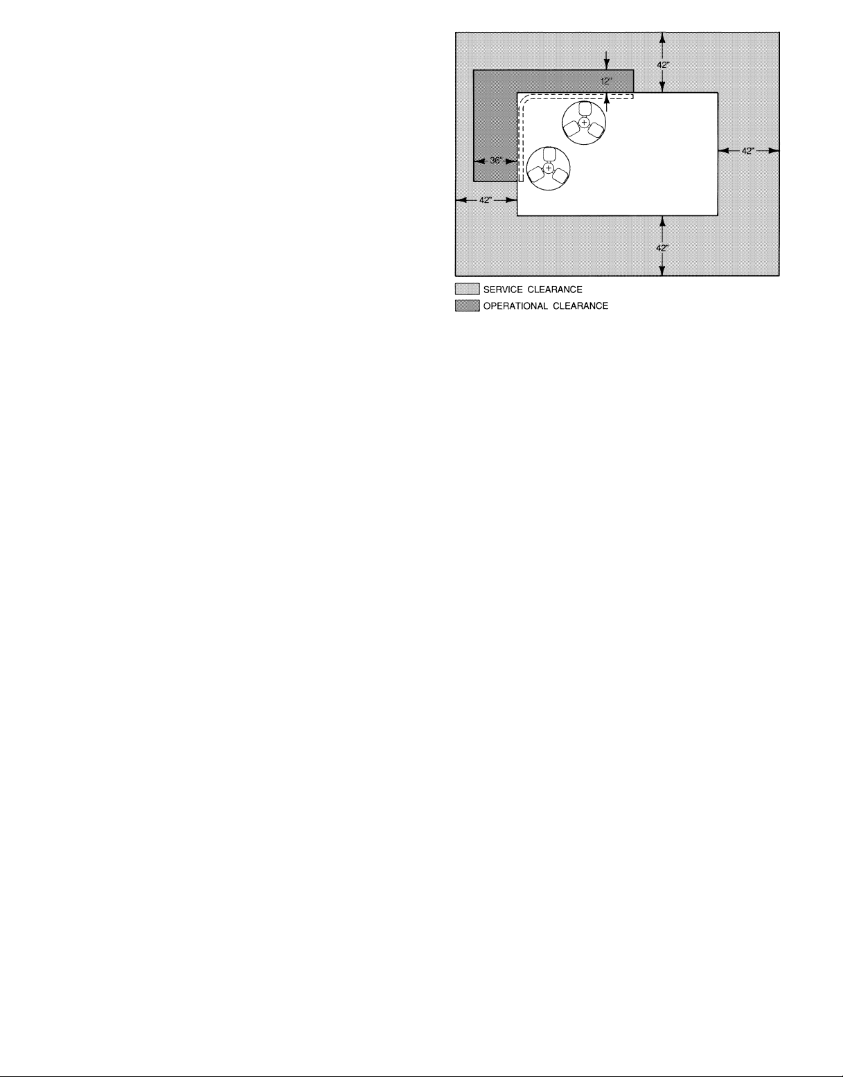
A. Clearance
Maintain clearance around and above unit to provide minimum distance from combustible materials, proper airflow ,and
service access. See Fig. 2 and 3.
Minimum clearance to combustibles (when not using curb) is
0 in. on vertical discharge units and 1 in. on horizontal discharge units.
Minimum clearance to block walls or any other grounded surface is 42 in. on all sides.
Minimum clearance of 42 in. should be provided between units
on side with control box. Between unit and ungrounded surfaces, control box side, clearance is 36 inches.
Minimum clearance around outdoor coil is 12 in. one side and
36 in. the other side (side getting greater clearance is
optional).
Overhead minimum clearance is 60 in.
Do not install unit in an indoor location. Do not locate unit
air inlets near exhaust vents or other sources of contaminated air.
Although unit is weatherproof, guard against water from higher
level runoff and overhangs.
Slab mounted units should be at least 4 in. above the highest
expected water, flood, and runoff levels. Do not use the unit if
it has been under water.
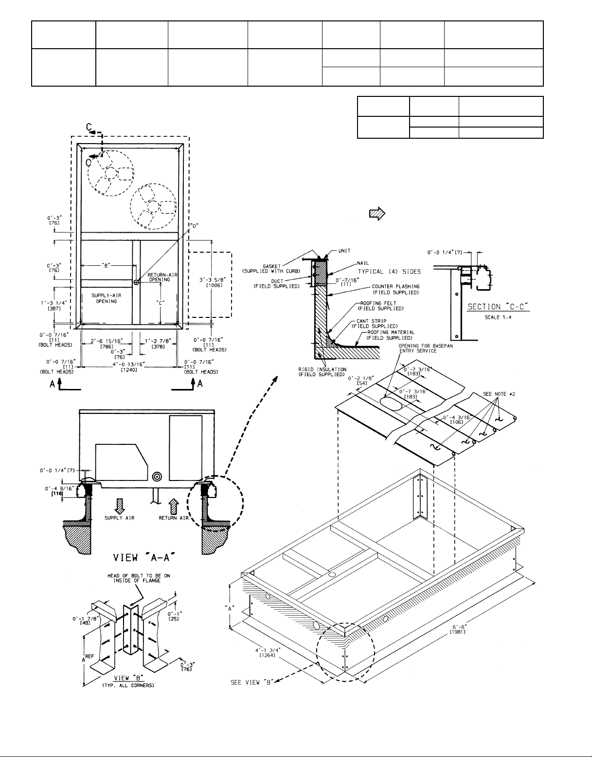
B. Roof Curb Mount
Assemble and install accessory roof curb in accordance with
instructions shipped with curb. See Fig. 4. Install insulation,
cant strips, roofing felt, and counter flashing as shown. Duct-
work must be attached to curb. If electric or control power is
to be routed through the basepan, attach the accessory thruthe-bottom connections to the basepan in accordance with the
accessory installation instructions. Accessory electric connections must be installed before unit is in place on roof curb.
IMPORTANT: The gasketing of the unit to the roof curb is
critical for water integrity. Install gasket with the roof curb
as shown in Fig. 4. Improperly applied gasket can also result
in air leaks and poor unit performance.
Curb should be level. Unit leveling tolerances are shown in
Fig. 5. This is necessary for unit drain to function
properly.
C. Slab Mount (Horizontal Units Only)
Provide a level concrete slab that extends a minimum of
6 in. beyond unit cabinet. Install a gravel apron in front of
outdoor-coil air inlet to prevent grass and foliage from obstructing airflow.
NOTE: Horizontal units may be installed on a roof curb if
required.
II. UNIT DUCT CONNECTIONS
On vertical units, secure all ducts to roof curb and building
structure. Do not connect ductwork to unit. On horizontal units,
duct flanges should be attached to horizontal openings and
all ductwork should be secured to flanges.
Fig. 3 — Service and Operational Clearances
Insulate and weatherproof all external ductwork, joints, and
roof openings with counter flashing and mastic in accordance
with applicable codes.
Ducts passing through an unconditioned space must be insulated and covered with a vapor barrier.
If a plenum return is used on a vertical unit, the return should
be ducted through the roof deck to comply with applicable
fire codes.
A minimum clearance to combustibles is not required
around ductwork on vertical discharge units. On horizontal
discharge units, a minimum clearance of 1 in. is required
for the first 12 in. of ductwork. Cabinet return-air static
shall not exceed –0.35 in. wg with Varislide™ economizer
−0.20 in. wg with PARABLADE economizer, or –0.45 in. wg
without economizer.
NOTE: Connection must be made to roof curb before unit is
set in place.
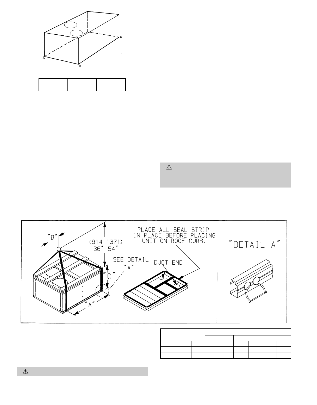
III. RIG AND PLACE UNIT
Inspect unit for transportation damage. File any claim with
transportation agency. Keep unit upright and do not drop.
Spreader bars are not required if top crating is left on unit.
Rollers may be used to move unit across a roof. Level by using unit frame as a reference. See Table 1 and Fig. 6 for additional information. Operating weight is shown in Fig. 6.
Lifting holes are provided in base rails as shown in Fig. 6.
Refer to rigging instructions on unit.
A properly positioned unit will have the following clearances
between unit and roof curb:
and base rails on each side and front of unit; 1
1
⁄4-in. clearance between roof curb
5
⁄32-in. clearance between roof curb and rear of unit. See Fig. 4, Views
A-A and C-C.
After unit is in position, remove polyethylene shipping wrapper and rigging skid.
—3—
UNIT SIZE
549B
090,120 28-8
‘‘B’’ ‘‘C’’
7
⁄169 [827] 18-1015⁄169 [583] 13⁄49 [45]
‘‘D’’ALT
DRAIN HOLE
POWER CONTROL
3
⁄49 NPT
1
1
⁄49 NPT
1
⁄29 NPT
1
⁄29 NPT
CONNECTOR
ACCESSORY
PACKAGE
CRBTMPWR00A100
(Thru-the-Bottom)
CRBTMPWR00A200
(Thru-the-Bottom)
UNIT SIZE
549B
090,120
NOTES:
1. Roof curb accessory is shipped unassembled.
2. Insulated panels.
3. Dimensions in [ ] are in millimeters.
4. Roof curb: galvanized steel.
5. Attach ductwork to curb (flanges of duct rest on curb).
6. Service clearance 4 ft on each side.
‘‘A’’
18-29 [356] CRRFCURB003A00
28-09 [610] CRRFCURB004A00
ROOF CURB
ACCESSORY
7. Direction of airflow.
Fig. 4 — Roof Curb Details
—4—
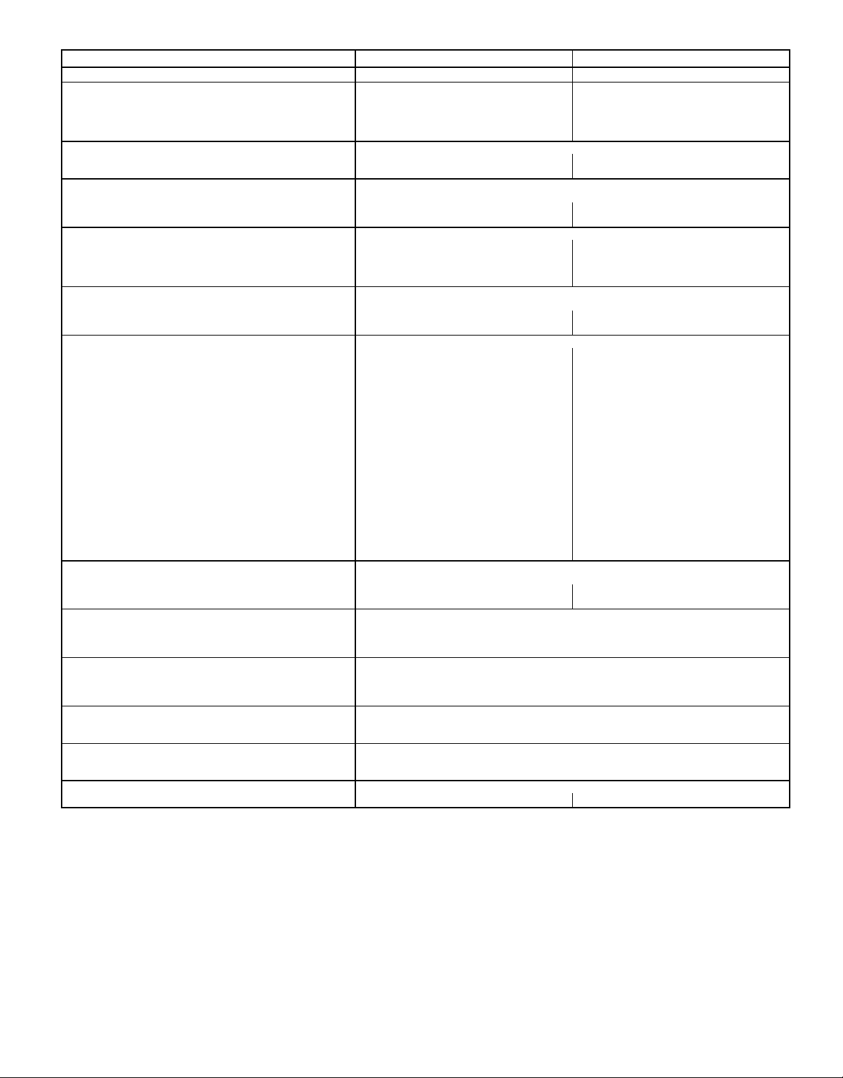
Table 1 — Specifications
UNIT 549B 090 120
1
⁄
1
⁄4...1100
7
⁄
8
2
Acutrol™ Feed Device
Acutrol Feed Device
1...16 x 25 x 1
NOMINAL CAPACITY (tons) 7
OPERATING WEIGHT (lb)
Unit 870 1000
With Varislide™ Economizer 914 1044
With PARABLADE Economizer 932 1062
Roof Curb 143 143
COMPRESSOR Scroll
Quantity 22
Oil (oz) (each compressor) 57 57
REFRIGERANT TYPE R-22
Operating Charge (lb-oz)
Circuit 1 5-3 9-11
Circuit 2 5-8 9-11
OUTDOOR FAN Propeller Type
Quantity...Diameter (in.) 2...22 2...22
Nominal Cfm 6500 7000
Motor Hp...Rpm
Watts Input (Total) 650 650
OUTDOOR COIL
Rows...Fins/in. 2...17 2...17
Total Face Area (sq ft) 20.5 25.1
INDOOR FAN Centrifugal Type, Belt Drive
Size (in.) 1...15 x 15 1...15 x 15
Nominal Cfm 3000 4000
Maximum Continuous Bhp 2.90 4.20
Motor Frame 56 56
Fan Rpm Range 725-925 860-1080
Motor Bearing Type Ball Ball
Maximum Fan Rpm 2100 2100
Motor Pulley Pitch Diameter A/B (in.) 3.4/4.4 4.0/5.0
Nominal Motor Shaft Diameter (in.)
Fan Pulley Pitch Diameter (in.) 8.0 8.0
Belt — Quantity...Type...Length (in.) 1...A...51 1...A...51
Pulley Center Line Distance (in.) 16.75-19.25 15.85-17.50
Speed Change per Full Turn of 50 45
Movable Pulley Flange (rpm)
Movable Pulley Maximum Full Turns 55
From Closed Position
Factory Setting — Full Turns Open 55
Factory Speed Setting (rpm) 725 860
Fan Shaft Diameter at Pulley (in.) 11
High-Efficiency Enhanced Copper Tubes, Lanced Aluminum Fins
INDOOR COIL High Efficiency Enhanced Copper Tubes, Aluminum Double-Wavy Fins,
Rows...Fins/in. 3...15 4...15
Total Face Area (sq ft) 8.9 11.1
HIGH-PRESSURE SWITCH (psig)
Standard Compressor Internal Relief 450±50
Cutout 428
Reset (Auto.) 320
LOSS-OF-CHARGE/LOW-PRESSURE
SWITCH (Liquid Line) (psig)
Cutout 7±3
Reset (Auto.) 22±7
FREEZE-PROTECTION THERMOSTAT
Opens (F) 30±5
Closes (F) 45±5
OUTDOOR-AIR INLET SCREENS Cleanable
Quantity...Size (in.) 1...20 x 25 x 1
RETURN-AIR FILTERS Throwaway
Quantity...Size (in.) 4...16 x 20 x 2 4...20 x 20 x 2
10
1
⁄4...1100
7
⁄
8
LEGEND
Bhp — Brake Horsepower
—5—
MAXIMUM ALLOWABLEDIFFERENCE (in.)
A-B B-C A-C
0.5 1.0 1.0
Fig. 5 — Unit Leveling Tolerances
IV. FIELD CONNECTIONS
A. External Trap Condensate Drain
The unit’s
3
⁄4-in. condensate drain connections are located
at the bottom and end of the unit. Unit discharge connections do not determine the use of drain connections; either
drain connection can be used with vertical or horizontal
applications.
When using the standard end drain connection, make sure
the plug in the alternate bottom connection is tight before
installing the unit.
To use the bottom drain connection for a roof curb installation, relocate the factory-installed plug from the bottom
connection to the end connection. See Fig. 7. The piping for
the condensate drain and external trap can be completed
after the unit is in place.
All units must have an external trap for condensate drainage. Install a trap at least 4-in. deep and protect against freezeup. See Fig. 8. If drain line is installed downstream from the
external trap, pitch the line away from the unit at 1 in. per
10 ft of run. Do not use a pipe size smaller than the unit
connection.
B. Field Duct Connections
NOTE: The design and installation of the duct system must
be in accordance with NFPA standards for the installation of
nonresidence-type air conditioning and ventilating systems,
NFPA No. 90A, or residence-type, NFPA No. 90B, and/or
local codes and ordinances.
Adhere to the following criteria when selecting, sizing, and
installing the duct system:
1. Remove appropriate panels from unit to obtain either
horizontal or vertical discharge. If units are installed in
horizontal discharge applications, remove vertical discharge duct covers, save screws, and install covers on
vertical duct openings.
2. Select and size ductwork, supply-air registers, and returnair grilles according to ASHRAE (American Society
of Heating, Refrigeration and Air Conditioning Engineers) recommendations.
CAUTION:
When drilling the duct system fastening
holes into the side of the unit for duct flanges, use extreme care not to puncture the coil or coil tubes. See
Fig. 9.
NOTES:
1. Dimension in ( ) is in millimeters.
2. Hook rigging shackles through holes in base rail, as shown in detail
9A.9 Holes in base rails are centered around the unit center of gravity. Use wooden top skid when rigging to prevent rigging straps from
damaging unit.
3. Unit weights do not include economizer. See Table 1 for economizer
weights.
CAUTION: All panels must be in place when rigging.
Fig. 6 — Rigging Details
—6—
OPERATING
UNIT
549B
090 870 395 87.38 2219 40.25 1022 41.31 1050
120 1000 454 87.38 2219 40.25 1022 49.31 1253
WEIGHT
lb kg in. mm in. mm in. mm
(A((B((C(
DIMENSIONS
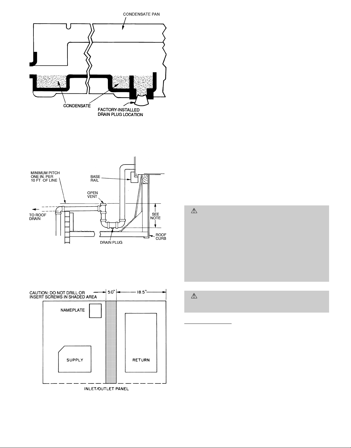
NOTE: Drain plug is shown in factory-installed position.
Fig. 7 — Condensate Drain Pan
3. Use flexible transition between rigid ductwork and unit
to prevent transmission of vibration. The transition may
be screwed or bolted to duct flanges. Use suitable gaskets to ensure weather- and airtight seal.
4. When horizontal return is used, install external fieldsupplied air filters in return-air ductwork where they
are easily accessible for service. Recommended filter sizes
are shown in Table 1.
5. For horizontal applications, be sure ductwork does not
cover nameplate.
6. Size all ductwork for maximum required airflow (either
heating or cooling) for unit being installed.Avoidabrupt
duct size increases or decreases.
7. Adequately insulate and weatherproof all ductwork
located outdoors. Insulate ducts passing through unconditioned space, and use vapor barrier in accordance with
latest issue of SMACNA (Sheet Metal and Air Conditioning Contractors National Association) and ACCA
(Air Conditioning Contractors of America) minimum
installation standards for heating and air conditioning
systems. Secure all ducts to building structure.
A minimum clearance to combustibles is not required
around ductwork on vertical discharge units. On horizontal discharge units, a minimum clearance of 1 in. is
required for the first 12 in. of ductwork.
8. Flash, weatherproof, and vibration isolate all openings
in building structure in accordance with local codes and
good building practices.
NOTE: Trap should be deep enough to offset maximum unit static diffrence. A 4-in. trap is recommended.
Fig. 8 — External Trap Condensate Drain
Fig. 9 — Location of Coil Area
Not to be Drilled
C. Electrical Connections
WARNING:
The unit cabinet must have an uninterrupted, unbroken, electrical ground to minimize the
possibility of personal injury if an electrical fault should
occur. This ground may consist of electrical wire connected to the unit ground lug in the control compartment, or conduit approved for electrical ground when
installed in accordance with NEC ANSI (American
National Standards Institute)/NFPA70-1990(inCanada,
Canadian Electrical Code CSA [Canadian Standards
Association] C22.1) and local electrical codes. Failure
to adhere to this warning could result in personal
injury.
CAUTION:
Failure to obey the following precautions could result in damage to the unit being
installed:
Field Power Supply
1. Make all electrical connections in accordance with NEC
ANSI/NFPA 70-1990 and local electrical codes governing such wiring. In Canada, all electrical connections must be in accordance with CSA Standard C22.1
Canadian Electrical Code Part One and applicable local
codes. Refer to unit wiring diagram.
2. A unit disconnect switch is required within sight
from the unit. The disconnect switch may be mounted
on the unit corner post (see Fig. 2). When mounting disconnect switch, be sure the unit rating plate is not
obstructed.
NOTE: A factory-installed disconnect switch is available.
—7—
3. Use only copper or copper-clad conductor for connections between field-supplied electrical disconnect switch
and unit. The use of aluminum wire is not recommended. Maximum wire size is no. 2 AWG (American
Wire Gage) on units with heat(up to 34 kW). The maximum wire size is no. 2/0 AWG on units with heat (over
34 kW).
4. Units with accessory electric heat must also have the
correct single point box kit to meet UL (Underwriters’
Laboratories) requirements. Refer to installation instructions shipped with the accessory for more details.
5. Voltage to compressor terminals during operation must
be within voltage range indicated on unit nameplate (also
see Tables 2A and 2B). On 3-phase units, voltages between phases must be balanced within 2% and the current within 10%. Use the formula shown in Tables 2A
and 2B, Note 2 to determine the percent voltage imbalance. Operation on improper line voltage or excessive
phase imbalance constitutes abuse and may cause damage to electrical components. Such operation would invalidate any applicable warranty.
6. Insulate low-voltage wires for highest voltage contained within conduit when low-voltage control wires are
run in same conduit as high-voltage wires. Install conduit through side panel openings. For units without accessory electric heat, install conduit between disconnect
and control box.
7. Do not damage internal components when drilling through
any panel to mount electrical hardware, conduit, etc.
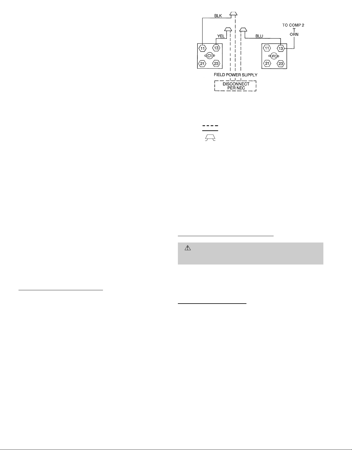
8. Install power lines to terminal connections as shown in
Fig. 10.
9. For units with accessory electric heat, refer to accessory
installation instructions for wiring the accessory.
During operation, voltage to compressor terminals must be
within range indicated on unit nameplate (see Tables 2A and
2B). On 3-phase units, voltages between phases must bebalanced within 2%, and the current within 10%. Use the formula shown in Tables 2A and 2B, Note 2 to determine the
percentage of voltage imbalance. Operation on improper line
voltage or excessive phase imbalance constitutes abuse and
may cause damage to electrical components. Such operation
would invalidate any applicable warranty.
High-Voltage Connections (Fig. 10)
The unit must have a separate electrical service with a field-
supplied, waterproof fused disconnect switch mounted at, or
within sight from, the unit. Refer to the unit rating plate for
maximum fuse/circuit breaker size and minimum circuit amps
(ampacity) for wire sizing. Be sure disconnect switch does not
obstruct unit rating plate. A factory-installed disconnect is
available.
The field-supplied disconnect switch box may be mounted on
the unit over the high-voltage inlet holein the control corner
panel.
Proceed as follows to complete the high-voltage connections
to the unit:
1. Connect ground lead to chassis ground connection when
using separate ground wire.
LEGEND
C—Contactor
COMP — Compressor
IFC — Indoor Fan Contactor
NEC — National Electrical Code
Field Wiring
Factory Wiring
Splice Connection (Factory-Supplied)
Fig. 10 — Power Wiring Connections
2. Pigtails are provided for field power connection. Use
factory-supplied splices or UL-approved copper/aluminum
connector .Install conduit connectors in side panel power
supply knockout openings indicated in Fig. 2. Route power
lines through connector to unit control box.
NOTE: If accessory thru-the-bottom power connections are
used, refer to the accessory installation instructions for information on power wiring. Refer to Fig. 2 for drilling holes
in basepan.
Special Procedures for 208-V Operation
DANGER: Make sure that the power supply to the
unit is switched off before making any wiring changes.
Electrical shock can cause personal injury or death.
For operation on 208 v, disconnect the black wire from the
230-v orange wire on the transformer and connect it to the
200-v red wire from the transformer. Insulate the end of the
orange wire.
Control Voltage Connections
Install a factory-approved room thermostat. See Table 3,
page 11.Locate the thermostat on an inside wall in the space
to be conditioned where it will not be subjected to either a
cooling or heating source or direct exposure to sunlight. Mount
the thermostat 4 to 5 ft above the floor.
NOTE: For wire runs up to 50 ft, use no. 18 AWG insulated
wire (35 C minimum). For 51 to 75 ft, use no. 16 AWG insulated wire (35 C minimum). For 76 to 155 ft, use no. 14 AWG
insulated wire (35 C minimum). All wire larger than no. 18
AWG cannot be connected directly tothe thermostat and will
require a junction box and splice at the thermostat.
—8—
Route thermostat cable or equivalent single leads of colored
wire from subbase terminals to low-voltage connections on
unit (shown in Fig. 11) as described in Steps 1 through 4
below.
1. If unit is mounted on roof curb and accessory thru-thebottom service connections are used, route wire through
basepan.
2. Pass control wires through the hole provided on unit (see
connection D in Connection Sizes table in Fig. 2).
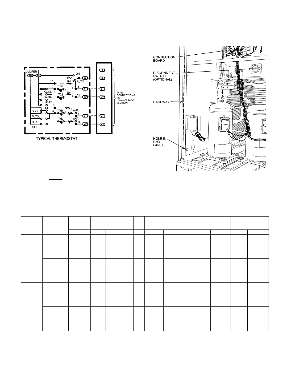
LEGEND
AHA — Adjustable Heat Anticipator
CC — Cooling Compensator
RC — 24 V Cooling
RH — 24 V Heating
TC — Thermostat-Cooling
TH — Thermostat-Heating
Field Wiring
Factory Wiring
Fig. 11 — Low-Voltage Connections With or
Without Economizer
3. Feed wire through the raceway built into the corner post
to the 24-v barrier located on the left side of the control
box. See Fig. 12. The raceway provides the ULrequired
clearance between the high- and low-voltage wiring.
4. Connect thermostat wires to screw terminals of lowvoltage connector (see Fig. 11).
Fig. 12 — Field Control Wiring Raceway
UNIT
549B
090
1
(7
⁄2Tons)
120
(10 Tons)
Table 2A — Electrical Data (Units Without Electrical Convenience Outlet)
NOMINAL
VOLTAGE
(V-Ph-Hz)
208/230-3-60 187 254 12.4 88.0 1.4 7.5
460-3-60 414 508 6.4 44.0 0.7 3.4
208/230-3-60 187 254 19.3 123.0 1.4 10.6
460-3-60 414 508 10.0 62.0 0.7 4.8
VOLTAGE
RANGE
Min Max RLA LRA FLA FLA kW† FLA MCA MOCP FLA LRA
COMPRESSOR OFM IFM ELECTRIC HEAT* POWER SUPPLY
—/—
7.8/10.4
12.0/16.0
18.6/24.8
24.0/32.0
31.8/42.4
—
13.9
16.5
27.8
33.0
41.7
—/—
7.8/10.4
12.0/16.0
24.0/32.0
31.8/42.4
37.6/50.0
—
16.5
27.8
33.0
41.7
50.0
—/—
21.7/ 25.0
33.3/ 38.5
51.6/ 59.7
66.6/ 77.0
88.3/102.0
—
16.7
19.8
33.4
39.7
50.2
—/—
21.7/ 25.0
33.3/ 38.5
66.6/ 77.0
88.3/102.0
104.4/120.3
—
19.8
33.4
39.7
50.2
60.1
38.2/ 38.2
65.3/ 69.5
79.8/ 86.3
102.7/112.8
121.5/134.5
148.6/165.7
19.2
40.1
44.0
61.0
68.8
82.0
56.8/ 56.8
84.0/ 88.1
98.5/105.0
140.1/153.1
167.2/184.3
187.3/177.1
28.7
53.3
70.5
78.3
91.5
88.8
40/ 40**
70/ 70
80/ 90
110/125
125/150
150/175
20**
45**
45**
70
70
90
60/ 60**
90/ 90
100/110
150/175
175/200
200/200
30**
60**
80
80
100
100
MINIMUM UNIT
DISCONNECT
SIZE
40/ 40
65/ 69
79/ 85
100/109
117/129
142/158
60/ 60
85/ 89
98/104
136/148
161/177
180/198
20
39
43
59
66
78
30
53
69
76
88
99
242/242
264/267
275/281††
294/302††
309/319††
330/344††
337/337
358/362††
370/375††
403/414††
425/439††
441/457††
121
138
141
155
161
171
170
189
203
209
220††
230††
—9—
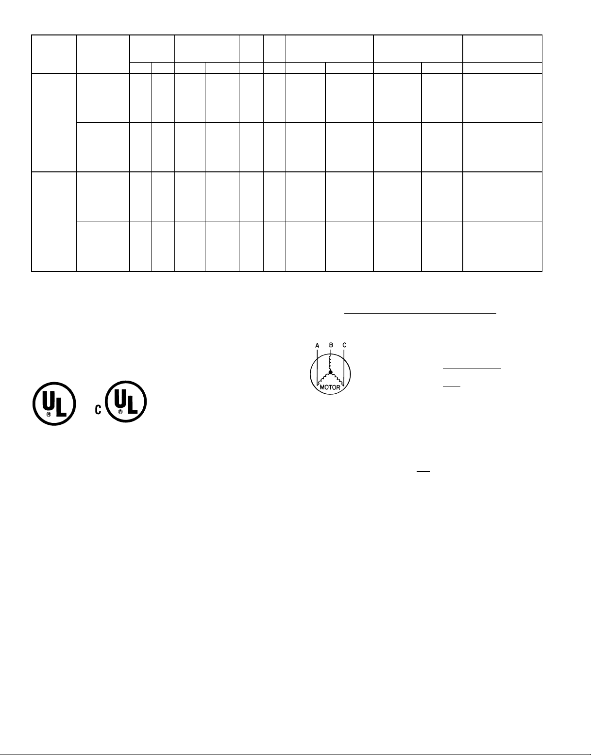
Table 2B — Electrical Data (Units With Electrical Convenience Outlet)
UNIT
549B
NOMINAL
VOLTAGE
(V-Ph-Hz)
VOLTAGE
RANGE
COMPRESSOR OFM IFM ELECTRIC HEAT* POWER SUPPLY
Min Max RLA LRA FLA FLA kW† FLA MCA MOCP FLA LRA
208/230-3-60 187 254 12.4 88.0 1.4 7.5
009
1
(7
⁄2Tons)
460-3-60 414 508 6.4 44.0 0.7 3.4
208/230-3-60 187 254 19.3 123.0 1.4 10.6
120
(10 Tons)
460-3-60 414 508 10.0 62.0 0.7 4.8
LEGEND AND NOTES TO TABLES 2A AND 2B
LEGEND
FLA — Full Load Amps
HACR — Heating, Air Conditioning and Refrigeration
IFM — Indoor Fan Motor
LRA — Locked Rotor Amps
MCA — Minimum Circuit Amps
MOCP — Maximum Overcurrent Protection
NEC — National Electrical Code
OFM — Outdoor Fan Motor
RLA — Rated Load Amps
*Used to determine minimum disconnect per NEC.
†Heater capacity (kW) is based on heater voltage of 208 v, 240 v,
or 480 v. If power distribution voltage to unit varies from rated heater
voltage, heater kW will vary accordingly.
**Fuse or HACR circuit breaker.
††Factory-installed disconnect is not available for these units when elec-
tric heat package is installed.
NOTES:
1. In compliance with NEC requirements for multimotor and combination load and equipment (refer to NEC Articles 430 and 440), the
overcurrent protective device for the unit shall be fuse or HACR breaker.
2. Unbalanced 3-Phase Supply Voltage
Never operate a motor where a phase imbalance in supply voltage is
greater than 2%.
age of voltage imbalance.
Use the following formula to determine the percent-
MINIMUM UNIT
DISCONNECT
SIZE
—/—
7.8/10.4
12.0/16.0
18.6/24.8
24.0/32.0
31.8/42.4
—
13.9
16.5
27.8
33.0
41.7
—/—
7.8/10.4
12.0/16.0
24.0/32.0
31.8/42.4
37.6/50.0
—
16.5
27.8
33.0
41.7
50.0
—/—
21.7/ 25.0
33.3/ 38.5
51.6/ 59.7
66.6/ 77.0
88.3/102.0
—
16.7
19.8
33.4
39.7
50.2
—/—
21.7/ 25.0
33.3/ 38.5
66.6/ 77.0
88.3/102.0
104.4/120.3
—
19.8
33.4
39.7
50.2
60.1
43.0/ 43.0
70.1/ 74.3
84.6/ 91.1
107.5/117.6
126.3/139.3
153.4/170.5
21.4
42.3
46.1
63.1
71.0
84.1
61.6/ 61.6
88.8/ 92.9
103.3/109.6
144.9/157.9
172.0/189.1
192.1/181.9
30.9
55.6
72.6
80.5
93.6
91.0
45/ 45**
80/ 80
90/100
110/125
150/150
175/175
25**
45**
50**
70
80
90
70/ 70
90/100
110/110
150/175
175/200
200/200
35**
60**
80
90
100
100
46/ 46
71/ 75
84/ 90
105/115
122/134
147/163
23
42
46
61
68
80
65/ 65
90/ 94
104/110
142/154
167/183
185/204
33
55
71
78
90
102
247/247
269/272
280/285††
298/307††
313/324††
335/349††
123
140
143
157
163
174
341/341
363/366††
375/380††
408/418††
430/443††
446/462††
172
191
205
211
222††
232††
% Voltage Imbalance
= 100 x
max voltage deviation from average voltage
average voltage
EXAMPLE: Supply voltage is 460-3-60
AB = 452 v
BC = 464 v
AC = 455 v
Average Voltage =
452 + 464 + 455
1371
=
3
3
= 457
Determine maximum deviation from average voltage:
(AB) 457 – 452=5v
(BC) 464 – 457=7v
(AC) 457 – 455=2v
Maximum deviation is 7 v.
Determine percentage of voltage imbalance:
% Voltage imbalance = 100 x
7
457
= 1.53%
This amount of phase imbalance is satisfactory as it is below the
maximum allowable 2%.
IMPORTANT: If the supply voltage phase imbalance is more than 2%
contact your local electric utility company immediately.
—10—
 Loading...