

Bryant 542J Series, 542J150, 542J180 Installation, Start-up And Service Instructions Manual
installation, start-up and
service instructions
SINGLE PACKAGE ROOFTOP
HEAT PUMP UNITS
IMPORTANT — READ BEFORE INSTALLING
1. Read and become familiar with these installation
instructions before installing this unit (Fig. 1).
2. Be sure the installation conforms to all applicable local
and national codes.
3. These instructionscontainimportantinformation for the
proper maintenance and repair of this equipment. Retain these instructions for future use.
CONTENTS
Page
SAFETY CONSIDERATIONS ........................1
INSTALLATION .................................1-13
I. Locate the Unit .............................4
II. Unit Duct Connections ......................6
III. Rig and Place Unit ..........................6
IV. Field Connections ..........................6
PRE-START-UP .................................13
START-UP ....................................13-19
I. Heating Section Start-Up and Adjustments ....13
II. Cooling Section Start-Up and Adjustments ....14
III. Indoor Airflow and Airflow Adjustments .......15
CARE AND MAINTENANCE .......................20
I. Air Filter ..................................20
SERVICE .....................................20-24
I. Cleaning .................................20
II. Lubrication ...............................20
III. Indoor Fan Performance Adjustment .........21
IV. Indoor Fan Service and Replacement .........22
V. Economizer Adjustment ....................22
VI. Power Failure .............................23
VII. Refrigerant Charge .........................23
VIII. Filter Drier ................................23
IX. Protective Devices .........................23
X. Relief Devices .............................24
XI. Control Circuit, 24 V .......................24
XII. Replacement Parts .........................24
TROUBLESHOOTING ...........................24-30
START-UP CHECKLIST ..........................CL-1
SAFETY CONSIDERATIONS
Recognize safety information. This is the safety-alert symbol
( ). When you see this symbol on the unit and in instructions or manuals, be alert to the potential for personal
injury.
Understand the signal words — DANGER, WARNING, and
CAUTION. These words are used with the safety-alert symbol. Danger identifies the most serious hazards which will
result in severe personal injury or death. Warning indicates
a situation that could result in personal injury. Caution is
used to identify unsafe practices which would result in minor
personal injury or product and property damage.
542J
Size 150,180
13 and 15 Tons
Cancels: II 542J-150-1 II 542J-150-2
2/15/97
Fig.1—Typical 542J Unit
WARNING:
nance operations on unit, turn off main power switch
to unit. Electrical shock could cause personal injury.
1. The power supply (volts, hertz, and phase) must correspond to that specified on the unit rating plate.
2. The electrical supply provided by the utility must be
sufficient to handle unit load.
3. Refer to the Locate the Unit section on page 4 and
Fig. 2 and 3 for locations of electrical inlets, condensate
drain, duct connections, and required clearances before
setting unit in place.
4. This installation must conform with local building codes
and with NEC (National Electrical Code) or NFPA
(National Fire Protection Association) 54 TIA-54-84-1.
Refer to Provincial and local plumbing or wastewater
codes and other applicable local codes.
5. Approved for outdoor installation on wood flooring or on
class A, B, or C roof covering materials.
Unit is shipped in the vertical discharge configuration (see
Fig. 4). To convert to horizontal discharge, an accessory roof
curb or accessory horizontal adapter must be used. Remove
the horizontal duct cover and attach ductwork. Seals around
duct opening must be tight. See Fig. 5. To convert to concentric air distribution, a field-supplied and fabricated transition piece must be used. See Fig. 6 and 7.
All units can be connected to existing duct systems that are
properly sized and designed to handle an airflow of 300 to
500 cfm per each 12,000 Btuh of rated cooling capacity.
NOTE: When installing any accessory item, see the manufacturer’s installation instructions packaged with the
accessory. A qualified installer or agency must use only factoryauthorized kits or accessories when modifying this unit.
Before performing service or mainte-
INSTALLATION
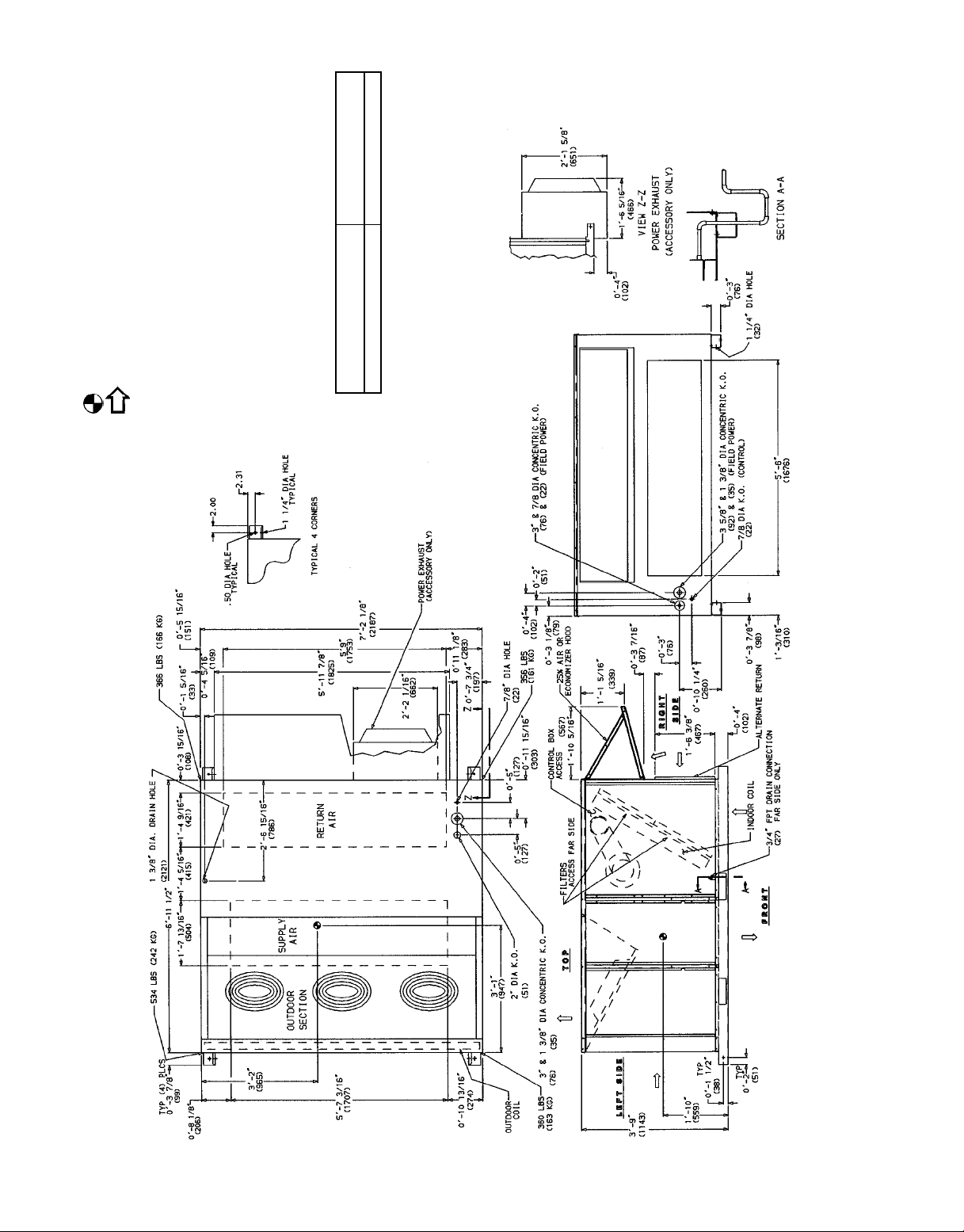
1. Refer to print for roof curb accessory dimensions.
2. Dimensions in ( ) are in millimeters.
3. Center of gravity.
4. Direction of airflow.
• Rear: 78-09 (2134) for coil removal. This dimension can be reduced to
5. Ductwork to be attached to accessory roof curb only.
6. Minimum clearance:
48-09 (1219) if conditions permit coil removal from the top.
• Left side: 48-09 (1219) for proper outdoor coil airflow.
• Front: 48-09 (1219) for control box access.
haust if so equipped.
• Top: 68-09 (1829) to assure proper outdoor fan operation.
• Right side: 48-09 (1219) for proper operation of damper and power ex-
exhaust as stated in note 6, a removable fence or barricade requires no
• Local codes or jurisdiction may prevail.
7. With the exception of clearance for the outdoor coil and the damper/ power
9 (8) on each side
16
⁄
5
clearance.
for top cover drip edge.
8. Dimensions are from outside of corner post. Allow 08-
WEIGHT
ECONOMIZER
WEIGHT
1615 lb (733 kg) 110 lb (50 kg)
STANDARD UNIT
—2—
Fig. 2 — Base Unit Dimensional Drawing — 542J150
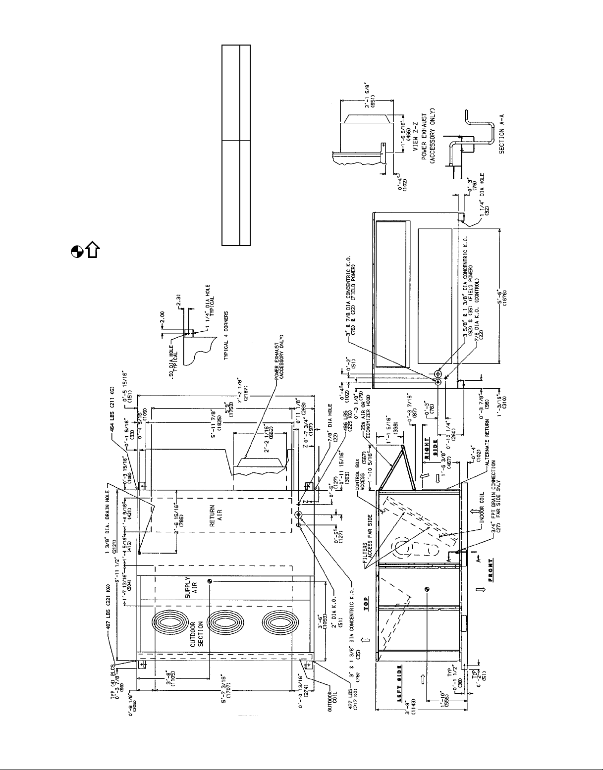
NOTES:
1. Refer to print for roof curb accessory dimensions.
2. Dimensions in ( ) are in millimeters.
9 (8) on each side
16
⁄
5
WEIGHT
ECONOMIZER
WEIGHT
1925 lb (874 kg) 110 lb (50 kg)
STANDARD UNIT
48-09 (1219) if conditions permit coil removal from the top.
haust if so equipped.
exhaust as stated in note 6, a removable fence or barricade requires no
• Rear: 78-09 (2134) for coil removal. This dimension can be reduced to
• Left side: 48-09 (1219) for proper outdoor coil airflow.
• Front: 48-09 (1219) for control box access.
3. Center of gravity.
4. Direction of airflow.
5. Ductwork to be attached to accessory roof curb only.
6. Minimum clearance:
• Right side: 48-09 (1219) for proper operation of damper and power ex-
• Local codes or jurisdiction may prevail.
• Top: 68-09 (1829) to assure proper outdoor fan operation.
7. With the exception of clearance for the outdoor coil and the damper/ power
clearance.
for top cover drip edge.
8. Dimensions are from outside of corner post. Allow 08-
—3—
Fig. 3 — Base Unit Dimensional Drawing — 542J180
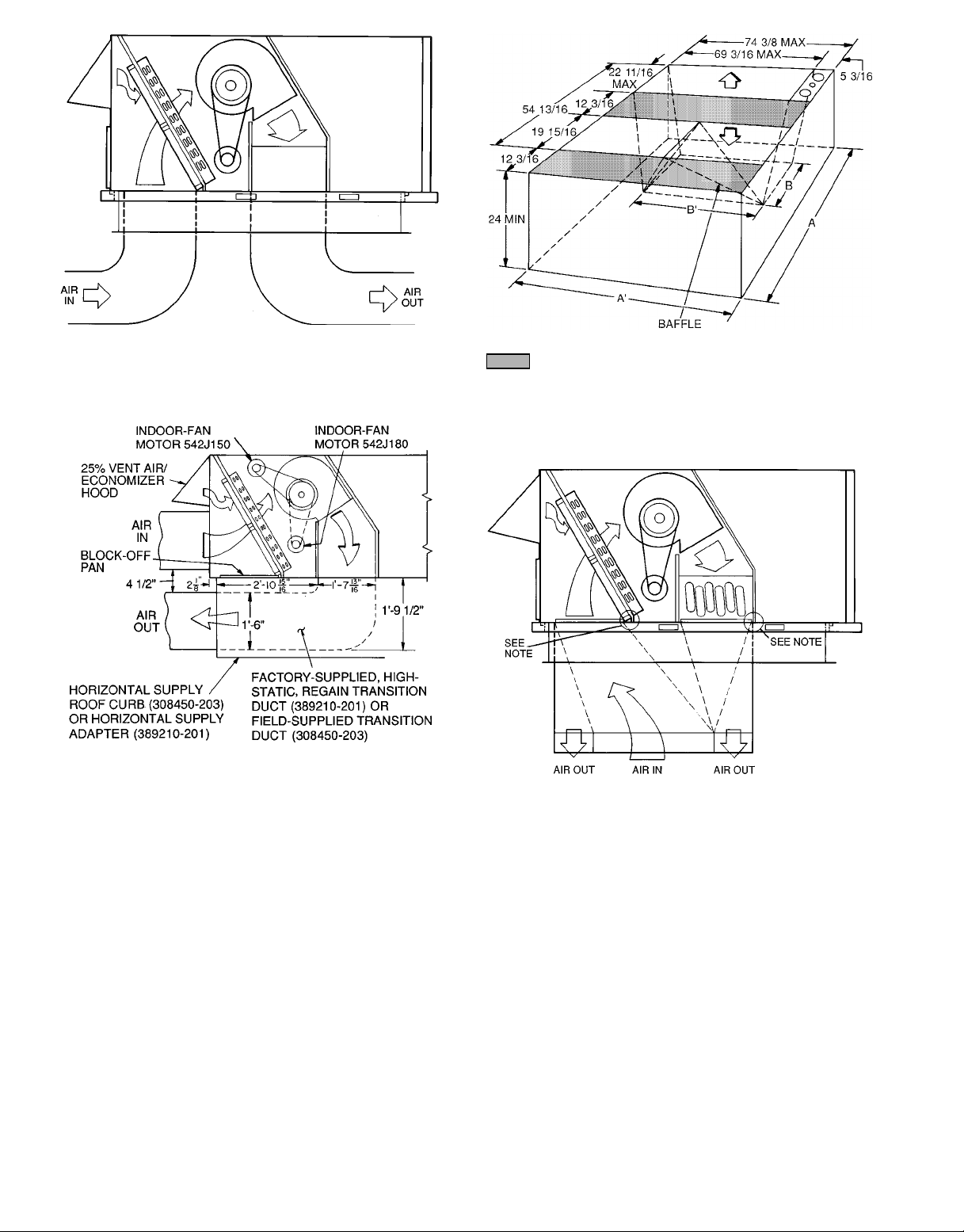
Fig. 4 — Air Distribution — Vertical Discharge
(Size 180 Shown)
NOTE: For preassembled horizontal adapter part no. 389210-201, the
accessory kit includes a factory-designed, high-static, regain transition
duct. For horizontal roof curb part no. 308450-203 (shown), a fieldsupplied transition duct is required.
Fig. 5 — Horizontal Supply/Return Roof Curb and
Adapter Details
Shaded area indicates block-off panels.
NOTES:
1. Dimensions A, A8 and B, B8 are obtained from field-supplied ceiling
diffuser.
2. Dimensions are in inches.
Fig. 6 — Concentric Duct Transition Piece
NOTE: Do not drill in this area; damage to basepan may result in water
leak.
Fig. 7 — Concentric Duct Air Distribution
(Size 180 Shown)
I. LOCATE THE UNIT
A. Clearance
Maintain clearance around and above unit to provide minimum distance from combustible materials, proper airflow,and
service access (see Fig. 2 and 3).
Minimum clearance to combustibles is 0 in. on all sides.
Minimum clearance to block walls or any other grounded sur-
face is 48 in. on all sides.
Minimum clearance between unit and other electrically live
parts is 48 inches.
Do not install unit in an indoor location. Do not locate unit
air inlets near exhaust vents or other sources of contaminated air.
Although unit is weatherproof, guard against water from higher
level runoff and overhangs.
Slab mounted units should be at least 4 in. above the highest
expected water, flood, and runoff levels. Do not use the unit if
it has been under water.
B. Roof Curb Mount
Assemble and install accessory roof curb in accordance with
instructions shipped with curb. See Fig. 8. Install insulation, cant strips, roofing, and counter flashing as shown.Duct-
work must be attached to curb. Electric and control power
can be routed through the curb or control box end panel (see
Fig. 2 and 3).
IMPORTANT: The gasketing of the unit to the roof curb is
critical for a watertight seal. Install gasket with the roof curb
as shown in Fig. 8. Improperly applied gasket can also
result in air leaks and poor unit performance.
Curb should be level. This is necessary for unit drain to function properly. Unit leveling tolerances are shown in Fig. 8.
—4—
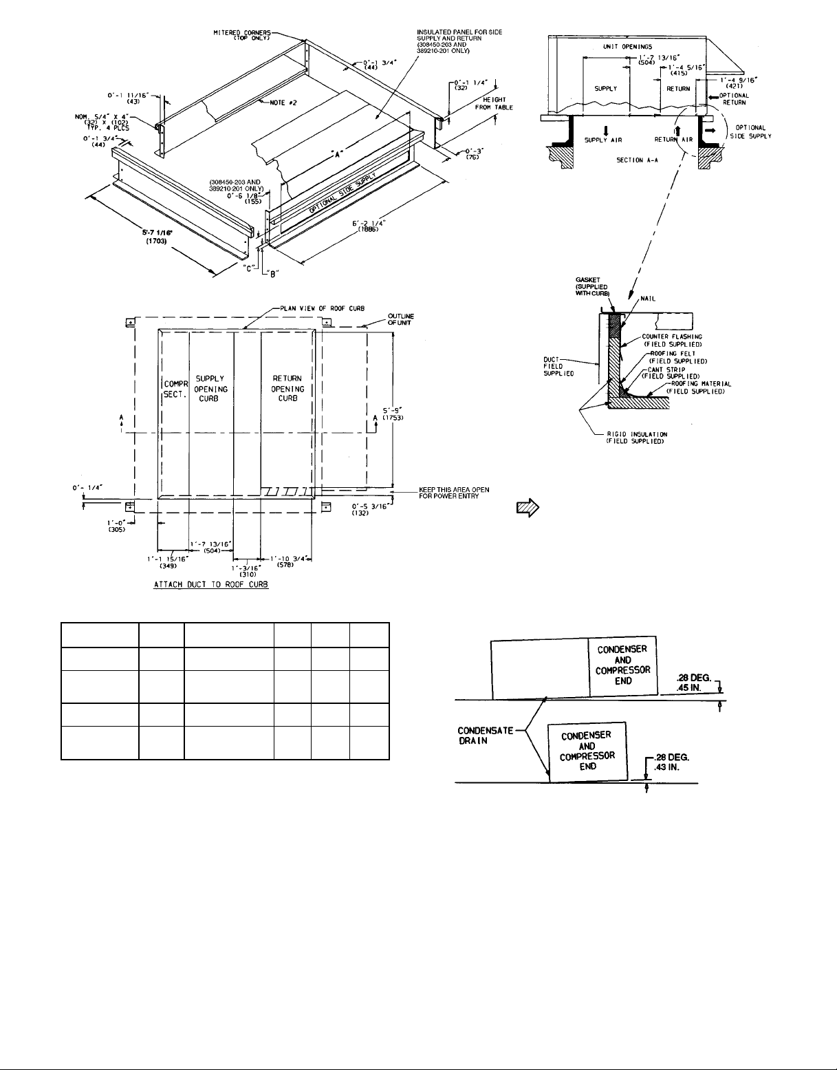
ACCESSORY
PACKAGE NO.
308450-201
308450-202
308450-203
389210-201
CURB
HEIGHT
18-29
(305)
28-09
(610)
28-09
(610)
18-119
(584)
DESCRIPTION ‘‘A’’ ‘‘B’’ ‘‘C’’
Standard Curb —
149 High
Standard Curb
for Units Requiring
High Installation
Horizontal Supply
and Return Curb
Pre-Assembled,
High-Static,
Horizontal Adapter
LEGEND
COMP SECT. — Compressor Section
Fig. 8 — Dimensional Drawing, Horizontal and Vertical Roof Curbs and Horizontal Adapter
———
———
1
⁄
2
9
(64)
(159)
18-69
(457)
1
⁄
4
9
18-25⁄
(371)
58-69
(1676)
68-29
(1880)
08-2
08-6
NOTES:
1. Roof curb accessory is shipped unassembled.
2. Insulated panels,
3. Dimensions in ( ) are in millimeters.
1
⁄2-in. thick neoprene-coated, 2 lb density.
4. Direction of airflow.
5. Roof curb: 18 gage steel.
6. Attach all ductwork to roof curb.
NOTE: To prevent the hazard of stagnant water build-up in the drain pan of the
indoor-air section, unit can only be pitched as shown.
8
9
—5—

C. Slab Mount (Horizontal Units Only)
Provide a level concrete slab that extends a minimum of
6 in. beyond unit cabinet. Install a gravel apron in front of
outdoor-coil air inlet to prevent grass and foliage from obstructing airflow.
NOTE: Horizontal units must be installed on accessory roof
curb or horizontal adapter. See Fig. 5, 8, and 9 for more
details.
II. UNIT DUCT CONNECTIONS
On vertical units, secure all ducts to roof curb and building
structure. Do not connect ductwork to unit. See Fig. 4. On
horizontal units, duct flanges should be attached to horizontal openings and roof curb part no. 308450-203 or horizontal
adapter part no. 389210-201 must be used.All ductwork should
be secured to flanges. See Fig. 5, 8, and 9.
For concentric units, a concentric transition piece must be
field supplied and field fabricated to adapt the unit. See
Fig. 6 and 7.
If a plenum return is used on a vertical unit, the return should
be ducted through the roof deck to comply with applicable
fire codes.
A minimum clearance to combustibles of 1 in. for the first
24 in. of ductwork is required for all units with electric heat.
Cabinet return-air static shall not exceed −0.35 in. wg with
economizer or −0.45 in. wg without economizer. Refer to
Accessory Roof Curb Installation Instructions for more
details.
NOTE: Connection must be made to roof curb before unit is
set in place.
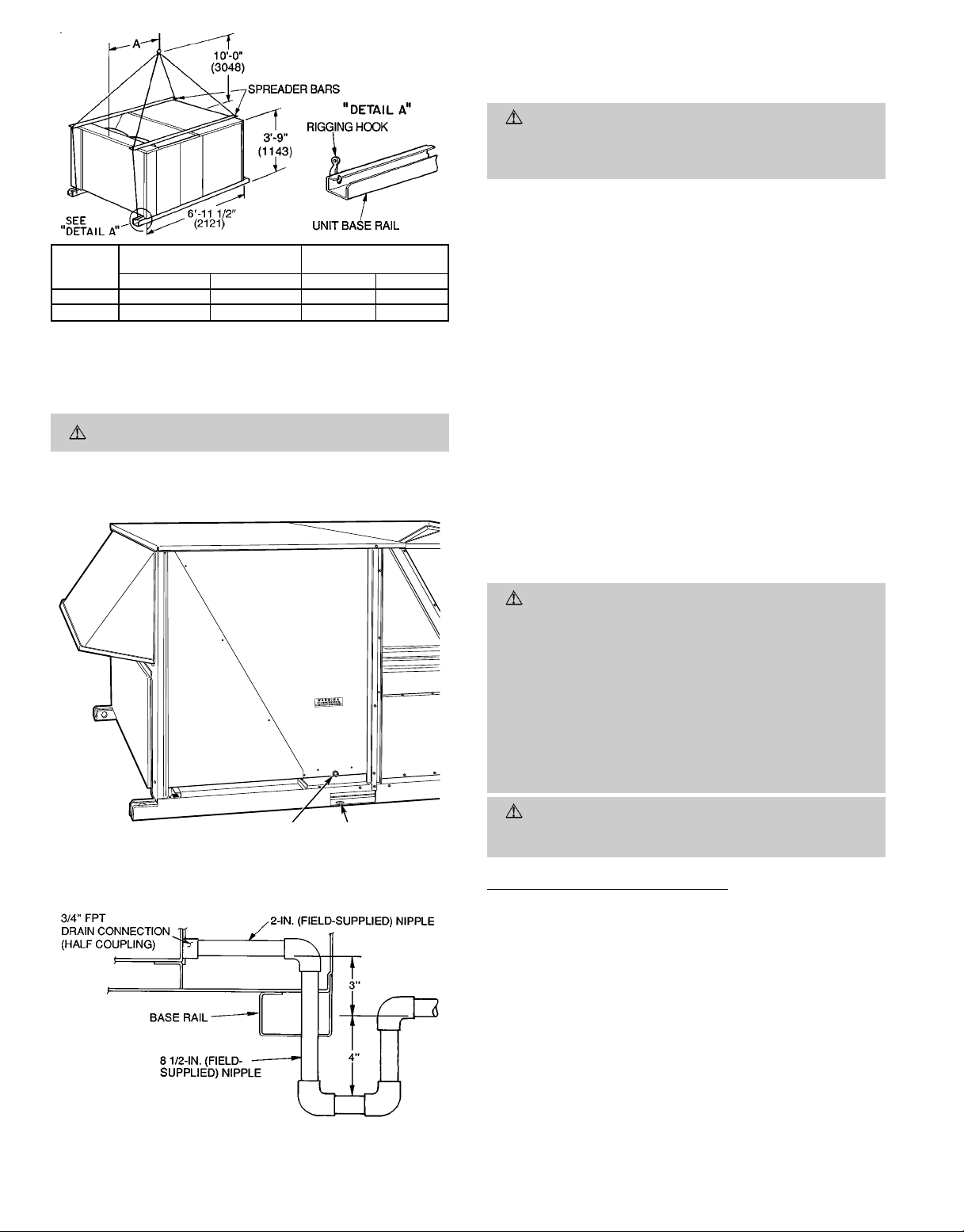
III. RIG AND PLACE UNIT
Inspect unit for transportation damage. File any claim with
transportation agency. Keep unit upright and do not drop.
Spreader bars are not required if top crating is left on
unit. Rollers may be used to move unit across a roof. Level
by using unit frame as a reference. See Table 1 and Fig. 10
for additional information. Operating weight is shown in
Table 1.
Four rigging holes are provided in base rails as shown in
Fig. 10. Refer to rigging instructions on unit.
IMPORTANT: Be sure to remove skids from under unit before setting unit in place.
A properly positioned unit will have the following clearances
1
between unit and roof curb:
⁄4-in. clearance between roof curb
and base rails on front, rear, and indoor air end of unit;
12-in. clearance between roof curb and compressor end of unit.
After unit is in position, remove polyethylene shipping wrapper and rigging skids.
IV. FIELD CONNECTIONS
A. Condensate Drain
3
See Fig. 11 for drain location. A
⁄4-in. half coupling is pro-
vided inside unit indoor-air section for condensate draincon-
1
nection. An 8
2 in. x
3
⁄4-in. diameter elbow provides a straight path down through
⁄2in. x3⁄4-in. diameter pipe nipple and a
3
⁄4-in. diameter pipe nipple coupled to a standard
holes in unit base rails (see Fig. 12).A trap at least 4 in. deep
must be used.
B. Field Duct Connections
NOTE: The design and installation of the duct system must
be in accordance with NFPA standards for the installation of
nonresidence-type air-conditioning and ventilating systems,
NFPA No. 90A or residence-type, NFPA No. 90B, and/or
local codes and ordinances.
Adhere to the following criteria when selecting, sizing, and
installing the duct system:
1. Unit comes shipped for vertical supply and return. If unit
is installed in horizontal discharge application, remove
vertical return-air duct cover, and install block-off pan
shipped with accessory horizontal supply curb or adapter
on vertical return-air duct openings. If unit is installed
with concentric duct connections, a concentric transition piece must be field-supplied and field-fabricated to
adapt for concentric duct connections. See Fig. 6 and 7
for airflow patterns and suggested dimensions for the
concentric duct transition piece.
NOTE: Part no. 389210-201 is a fully factory preassembled horizontal
adapter which includes an insulated high static regain transition duct
and substantially improves fan static performance.
Fig. 9 — Dimensional Drawing — Horizontal Adapter Installation
—6—
Table 1 — Specifications
UNIT SIZE 542J 150 180
OPERATING WT (lb)
Unit 1615 1925
Economizer 110 110
Roof Curb* 200 200
COMPRESSOR Semi-Hermetic
Type (Quantity) 060-328 (1) 060-818 (2)
No. Cylinders 64
Oil Charge (oz.) (Cool Circuit) 115 88
REFRIGERANT TYPE R-22
Charge (lb)
System 1 26.0 16.5
System 2 — 16.5
OUTDOOR COIL
Rows...Fins/in. 3...15 3...15
Total Face Area (sq ft) 21.7 21.7
OUTDOOR FAN Propeller Type, Direct Drive
Nominal Cfm 9,000
Number...Diameter (in.) 3...22
Motor Hp...Rpm
Watts Input (Total) 1090
INDOOR COIL
Expansion Device Fixed Orifice
Rows...Fins/in. 3...15 3...15
Total Face Area (sq ft) 17.5 17.5
INDOOR FAN Centrifugal Type
Quantity...Size (in.) 2...10 x 10 2...12 x 12
Type Drive Belt Belt
Nominal Cfm 5000 6000
Motor Hp 3.7 5.0
Maximum Continuous Bhp 4.25 5.90
Motor Frame Size 56H 184T
Fan Rpm Range 862-1132 799-1010
Motor Bearing Type Ball Ball
Maximum Allowable Rpm 1550 1550
Motor Pulley Pitch Diameter
Min/Max (in.)
Nomimal Motor Shaft Diameter (in.) 1
Fan Pulley Pitch Diameter (in.) 6.0 11.4
Belt, Quantity...Type...Length (in.) 1...BX...42 1...BX...46
Pulley Center Line Distance (in.) 13.5-15.5 13.3-14.8
Speed Change per Full Turn of
Movable Pulley Flange (rpm)
Movable Puley Maximum Full Turns
from Closed Position
Factory Setting 33
Factory Speed Setting (Rpm) 1024 926
Motor Efficiency 0.84 0.84
HIGH-PRESSURE SWITCH (psig)
Standard Compressor Internal Relief —
Cutout 426
Reset (Auto.) 320
LOW-PRESSURE SWITCH (psig)
Cutout 7
Reset (Auto.) 22
FREEZE PROTECTION THERMOSTAT (F)
Opens 30±5
Closes 45±5
3
⁄8in., Internally-Grooved Copper Tubes, Aluminum or Copper Lanced Fins, Acutrol™ Feed Device
OUTDOOR AIR INLET SCREENS Cleanable
Quantity...Size (in.)
RETURN-AIR FILTERS 10% Efficient — 2-in. Throwaway Fiberglass
Quantity... Size (in.)
DEFROST THERMOSTAT
Defrost Timer 30 Min (Adjustable to 50 or 90 Min)
Closes (F) 28
Opens (F) 65
LEGEND
Al — Aluminum
Bhp — Brake Horsepower
Cu — Copper
FIOP — Factory-Installed Option
3
⁄8in., Internally-Grooved Enhanced Copper Tubes, Aluminum Lanced Fins
1
⁄2...1075
3.1/4.1 3.7/4.7
3
⁄
16
17⁄
16
54 42
6† 6†
2...20 x 25 x 1
1...20 x 20 x 1
4...20 x 20 x 2
4...16 x 20 x 2
*Weight of 14 in. roof curb.
†Cannot be set to 0 or
NOTE: The 542J units have a low-pressure/loss-of-charge switch (standard) located on the suction side.
1
⁄2turns open.
—7—
2. Select and size ductwork, supply-air registers, and returnair grilles according to ASHRAE (American Society of
Heating, Refrigeration and Air Conditioning Engineers) recommendations.
UNIT
542J
150 1895 860 3-1 948
180 2205 1000 3-6 1059
NOTES:
1. Dimensions in ( ) are in millimeters.
2. Refer to Table 1 for unit operating weights.
3. Remove boards at ends of unit and runners prior to rigging.
4. Rig by inserting hooks into unit base rails as shown. Use corner post from packaging to protect coil from damage. Use bumper boards for spreader bars.
5. Weights do not include optional economizer. See T able1foreconomizer weight.
MAXIMUM SHIPPING
WEIGHT
Lb Kg Ft-in. mm
DIMENSION A
CAUTION: All panels must be in place when rigging.
Fig. 10 — Rigging Details
CAUTION:
On vertical supply and return units, when
drilling the duct system fastening holes into the bottom of the unit for duct flanges, use extreme care not to
puncture the basepan. See Fig. 7.
3. Use flexible transition between rigid ductwork and unit
to prevent transmission of vibration. The transition may
be screwed or bolted to duct flanges. Use suitable gaskets to ensure weather- and airtight seal.
4. Size all ductwork for maximum required airflow (either
heating or cooling) for unit being installed.Avoid abrupt
duct size increases or decreases.
5. Adequately insulate and weatherproof all ductwork
located outdoors. Insulate ducts passing through unconditioned space, and use vapor barrier in accordance with
latest issue of SMACNA (Sheet Metal and Air Conditioning Contractors National Association) and ACCA
(Air Conditioning Contractors of America) minimum installation standards for heating and air-conditioning systems. Secure all ducts to building structure.
On units equipped with electric heat,a minimum clearance to combustibles of 1 in. for the first 24 in. of ductwork is required.
6. Flash, weatherproof, and vibration isolate all openings
in building structure in accordance with local codes and
good building practices.
C. Electrical Connections
3/4" FPT DRAIN
CONNECTION
1-3/4"
DRAIN HOLES
Fig. 11 — Condensate Drain Details
Fig. 12 — Condensate Drain Piping Details
WARNING:
The unit cabinet must have an uninterrupted, unbroken, electrical ground to minimize the
possibility of personal injury if an electrical fault
should occur. This ground may consist of electrical wire
connected to the unit ground lug in the control compartment, or conduit approved for electrical ground when
installed in accordance with the NEC ANSI (American
National Standards Institute) /NFPA 70 (in Canada,
Canadian Electrical Code CSA [Canadian Standards
Association] C22.1) and local electrical codes. Failure
to adhere to this warning could result in personal
injury.
CAUTION:
Failure to obey the following precautions could result in damage to the unit being
installed:
Field Power Supply (Fig. 13 and 14)
1. Make all electrical connections in accordance with NEC
ANSI/NFPA 70 and local electrical codes governing such
wiring. In Canada, all electrical connections must be in
accordance with CSA Standard C22.1 Canadian Electrical Code Part One and applicable local codes. Refer to
unit wiring diagram.
2. A unit disconnect switch is required within sight from
the unit. The disconnect switch may be mounted on the
unit corner post. When mounting disconnect switch, be
sure the unit rating plate is not obstructed.
3. Use only copper or copper-clad conductor for connections between field-supplied electrical disconnect switch
and unit. The use of aluminum wire is not recommended. See Fig. 13 for maximum wire size. For units
with electric heat, size wire per NEC recommendations.
—8—
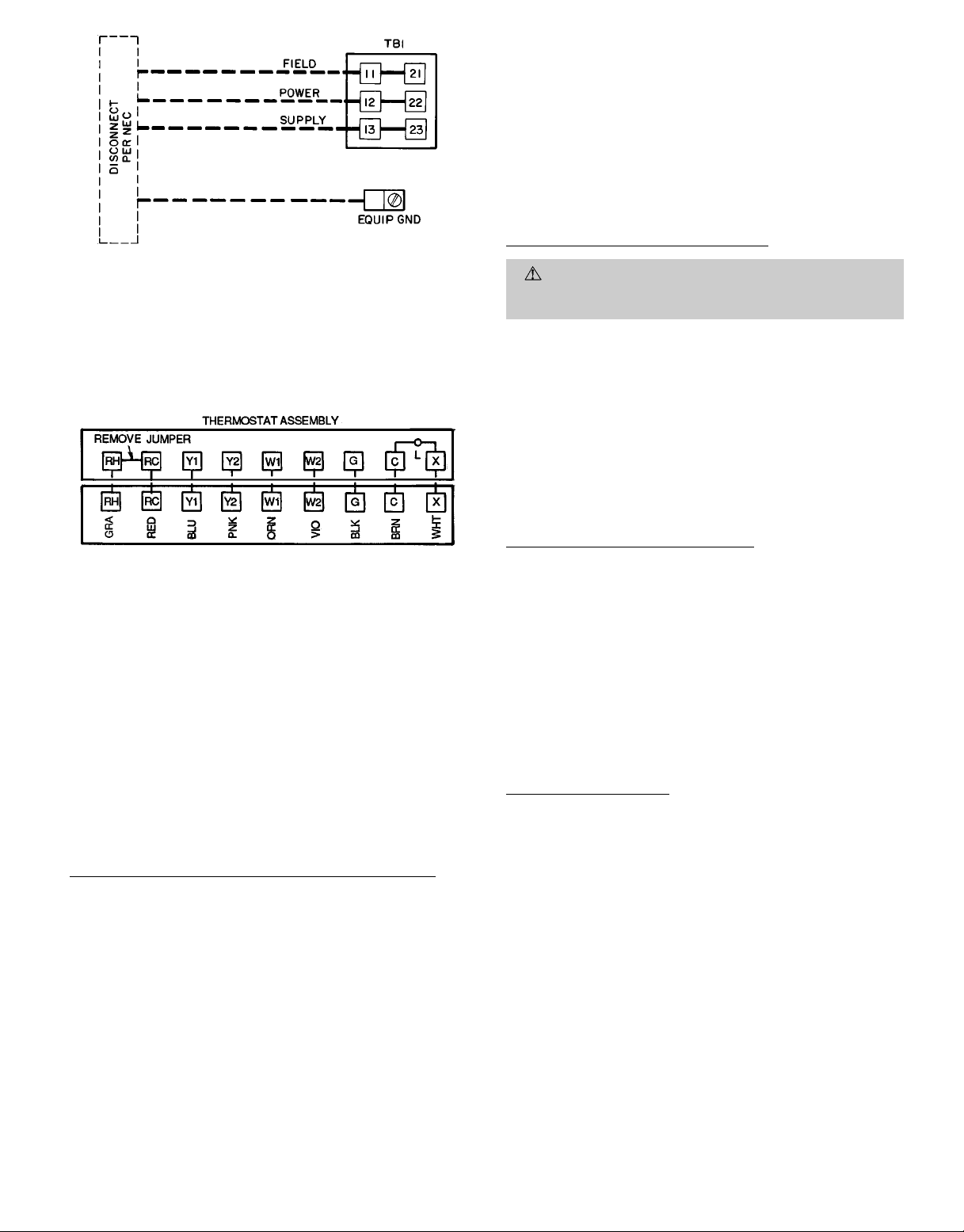
LEGEND
EQUIP GND — Equipment Ground
kcmil — Thousand Circular Mils
NEC — National Electrical Code
TB — Terminal Block
NOTE: The maximum wire size for TB1 is 350 kcmil for all unit voltages.
Fig. 13 — Field Power Wiring Connections
Fig. 14 — Field Control Thermostat Wiring
4. Voltage to compressor terminals during operation must
be within voltage range indicated on unit nameplate (also
see Table2). Voltagesbetween phases must be balanced
within 2% and the current within 10%. Use the formula
shown in Table 2, Note 3, todetermine the percent voltage imbalance. Operation on improper line voltage or
excessive phase imbalance constitutes abuse and may
cause damage to electrical components. Such operation
would invalidate any applicable warranty.
5. Insulate low-voltage wires for highest voltage contained within conduit when low-voltage control wires are
run in same conduit as high-voltage wires.
6. Do not damage internal components when drilling through
any panel to mount electrical hardware, conduit, etc.
High-Voltage Field Power Wiring Connections (Fig. 13)
The unit must have a separate electrical service with afield-
supplied, waterproof, fused disconnect switch mountedat, or
within sight from, the unit. Refer to the unit rating plate for
maximum fuse/circuit breaker size and minimum circuit amps
(ampacity) for wire sizing. Be sure disconnect switch does not
obstruct unit rating plate.
The field-supplied disconnect switchbox may be mounted on
the unit over the high-voltage inlet holein the control corner
panel.
Proceed as follows to complete the high-voltage connections
to the unit:
1. Connect ground lead to chassis ground connection when
using separate ground wire.
2. Unit has a terminal block for field power connections.
Install conduit connectors in side panel power supply
knockout openings indicated in Fig. 2 and 3. Route power
lines through connector to unit control box.
Special Procedures for 208-V Operation
DANGER: Make sure that the power supply to the
unit is switched off before making any wiring changes.
Electrical shock can cause personal injury or death.
For operation on 208 v:
1. Remove the cap from the splice containing the orange
(230 v) transformer primary lead and 2 black wires. See
unit wiring diagram.
2. Remove cap from the red (208 v) transformer primary
lead.
3. Use cap from red lead to splice red lead and 2 black wires
together.
4. Cap the orange lead.
5. Check to be sure no copper wire is left exposed at both
caps.
Control Voltage Connections (Fig. 14)
Install a factory-approved room thermostat. Refer to unit Trade
Prices or contact your local representative for more information. Locate the thermostat on an inside wall in the space to
be conditioned where it will not be subjected to either a cooling or heating source or direct exposure to sunlight. Mount
the thermostat 4 to 5 ft above the floor.
NOTE: For wire runs up to 50 ft, use no. 18AWG (American
Wire Gage) insulated wire (35 C minimum). For 51 to 75 ft,
use no. 16 AWG insulated wire (35 C minimum). For 76 to
155 ft, use no. 14 AWG insulated wire (35 C minimum). All
wire larger than no. 18 AWG cannot be connected directly to
the thermostat and will require a junction box and splice at
the thermostat.
Heat Anticipator Setting
The room thermostat heat anticipator must be properly ad-
justed to ensure proper heating performance. Set the heat
anticipator to settings in Table 3.
Failure to make a proper heat anticipator adjustment may
result in improper operation, discomfort to the occupants of
the conditioned space, and inefficientenergy utilization; however,the required setting may be changed slightlyto provide
a greater degree of comfort for a particular installation.
—9—
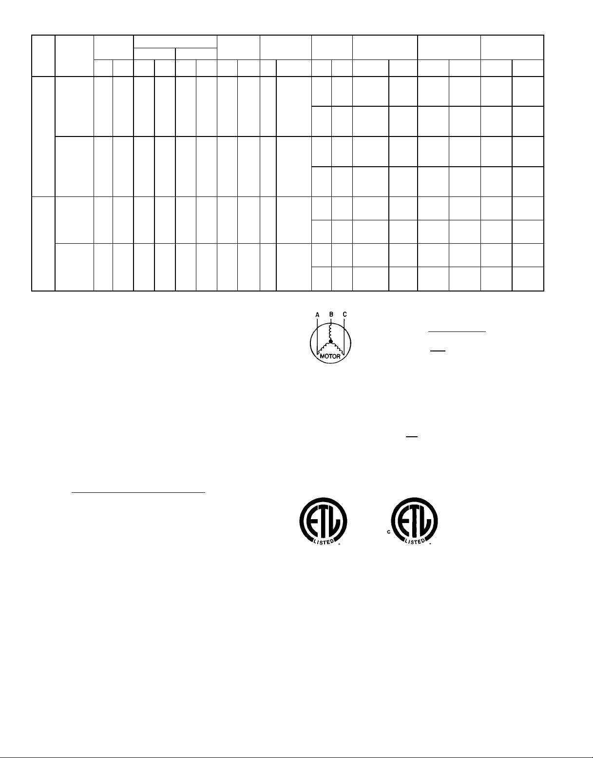
Table 2 — Electrical Data
VOLTAGE
UNIT
542J
150
180
FLA — Full Load Amps
HACR — Heating, Air Conditioning and Refrigeration
LRA — Locked Rotor Amps
MCA — Minimum Circuit Amps
MOCP — Maximum Overcurrent Protection
NEC — National Electrical Code
RLA — Rated Load Amps
*Heater capacity (kW) is based on heater voltage of 208 v, 240 v and 480 v. If
power distribution voltage to unit varies from rated heater voltage, heater kW will
vary accordingly.
†Fuse or HACR circuit breaker. This is the maximum size permissible; smaller
fuse size may be used where conditions permit.
NOTES:
1. In compliance with NEC requirements for multimotor and combination load equip-
2. MCA calculation for units with electric heaters over 50 kW
3. Unbalanced 3-Phase Supply Voltage
(3 Ph,
60 Hz)
208/230 187 253 39.7 228 — — 3 1.7 3.7 10.5/10.5
208/230 187 253 28.2 160 28.2 160 3 1.7 5 15.8/15.8
ment (refer to NEC Articles 430 and 440), the overcurrent protective device for
the unit shall be fuse or HACR breaker. The Canadian units may be fuse or
circuit breaker.
= (1.25 x IFM amps) + (1.00 x heater FLA).
Never operate a motor where a phase imbalance in supply voltage is greater
than 2%.
imbalance.
% Voltage Imbalance
= 100 x
VOLTAGE
RANGE
Min Max RLA LRA RLA LRA Qty
460 414 508 19.9 114 — — 3 0.8 3.7 4.8
460 414 508 14.1 80 14.1 80 3 0.8 5 7.9
LEGEND
Use the following formula to determine the percent of voltage
max voltage deviation from average voltage
average voltage
COMPRESSOR
No. 1 No. 2
OUTDOOR
FAN
MOTOR
FLA
(ea)
INDOOR FAN
Hp FLA FLA LRA FLA kW MCA MOCP† RLA LRA
MOTOR
POWER
EXHAUST
——
4.6 18.8
——
2.3 6.0
——
4.6 18.8
——
2.3 6.0
EXAMPLE: Supply voltage is 460-3-60.
Determine maximum deviation from average voltage.
(AB) 457 − 452 = 5 v
(BC) 464 − 457 = 7 v
(AC) 457 − 455 = 2 v
Maximum deviation is 7 v.
Determine percent of voltage imbalance.
% Voltage Imbalance = 100 x
This amount of phase imbalance is satisfactory as it is below the maximum
allowable 2%.
IMPORTANT: If the supply voltage phase imbalance is more than 2%,
contact your local electric utility company immediately.
ELECTRIC HEAT* POWER SUPPLY
−/−
39/ 45
72/ 82
117/135
−/−
39/ 45
72/ 82
117/135
—
18
39
66
—
18
39
66
—/—
72/ 82
117/135
—/—
72/ 82
117/135
—
39
66
—
39
66
AB = 452 v
BC = 464 v
AC = 455 v
Average Voltage =
14/19
26/34
42/56
14/19
26/34
42/56
—/—
26/34
42/56
—/—
26/34
42/56
= 1.53%
−/−
−/−
—
15
32
55
—
15
32
55
—
32
55
—
32
55
65/ 65
114/122
155/168
211/200
70/ 70
119/126
159/173
216/205
32
54
81
98
34
57
83
100
84/ 84
174/187
231/219
89/ 89
179/191
235/224
42
91
108
44
93
110
452 + 464 + 455
1371
=
= 457
7
457
3
100/100
125/150
175/175
225/225
100/100
125/150
175/175
225/225
50
60
90
110
50
70
90
110
110/110
175/200
250/225
110/110
200/200
250/225
50
100
110
50
100
125
3
147/167
100/112
152/173
101/112
153/173
106/118
158/179
DISCONNECT
SIZING
64/ 64
64/ 64
387/387
94/107
69/ 69
69/ 69
406/406
31
31
189
50
82
34
34
195
53
84
89/ 89
499/485
94/ 94
518/504
44
54
238
85
47
57
244
88
—10—
 Loading...