

Page 1

installation, start-up and
service instructions
SINGLE PACKA GE ROOFT OP
HEAT PUM P UNITS
Cancels: II 542J-150-3 II 542J-150-4
Dura
Pac
542J
Plus Series
Sizes 150,180
12 and 15 Tons
3/15/06
CONTENTS
Page
SAFETY CONSIDERATIONS . . . . . . . . . . . . . . . . . . . . . . . . . 1
INSTALLATION. . . . . . . . . . . . . . . . . . . . . . . . . . . . . . . . . 1-18
I. Step 1 — Provide Unit Support. . . . . . . . . . . . . . . . . 1
II. Step 2 — Rig and Place Unit. . . . . . . . . . . . . . . . . . . 1
III. Step 3 — Field Fabricate Ductwork . . . . . . . . . . . . . 1
IV. Step 4 — Make Unit Duct Connections . . . . . . . . . . 3
V. Step 5 — Trap Condensate Drain. . . . . . . . . . . . . . . 3
VI. Step 6 — Make Electrical Connections . . . . . . . . . . 7
VII. Step 7 — Make Outdoor-Air Inlet Adjustments. . . 10
VIII. Step 8 — Install Outdoor-Air Hood. . . . . . . . . . . . . 10
IX. Step 9 — Install All Accessories . . . . . . . . . . . . . . 10
X. Step 10 — Adjust Factory-Installed Options. . . . . 11
XI. Step 11 — Defrost Cycle . . . . . . . . . . . . . . . . . . . . . 18
START-UP . . . . . . . . . . . . . . . . . . . . . . . . . . . . . . . . . . . . .18-22
SERVICE. . . . . . . . . . . . . . . . . . . . . . . . . . . . . . . . . . . . . .23-29
TROUBLESHOOTING. . . . . . . . . . . . . . . . . . . . . . . . . . . .30-35
INDEX . . . . . . . . . . . . . . . . . . . . . . . . . . . . . . . . . . . . . . . . . . 36
START-UP CHECKLIST . . . . . . . . . . . . . . . . . . . . . . . . . . CL-1
SAFETY CONSIDERATIONS
Installation and servicing of air-conditioning equipment can
be hazardous due to system pressure and electrical components. Only trained and qualified service personnel should
install, repair, or service air-conditioning equipment.
Untrained personnel can perform basic maintenance functions of cleaning coils and filters and replacing filters. All
other operations should be performed by trained se rvice personnel. When working on air-conditioning equipment, observe
precautions in the literature, tags and labels attached to the
unit, and other safety pre c au ti ons th at ma y a ppl y.
Follow all safety codes. Wear safety glasses and work gloves.
Use quenching cloth for unbrazing operations. Have fire
extinguisher available for all brazing operations.
WARNING: Before performing service or maintenance operations on unit, turn off main power switch to
unit. Electrical shock could cause personal injury.
INSTALLATION
IMPORTANT: Units have high ambient operating limits. If
limits are exceeded , the un it will au tomatica lly lock the compressor out of operation. Manual reset will be required to
restart the compressor.
I. STEP 1 — PROVIDE UNIT SUPPORT
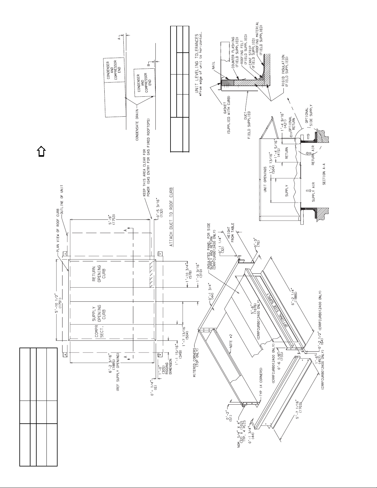
A. Roof Curb
Assemble and install a ccessory roof curb in accordanc e with
instructions shipped with the curb. Accessory roof curb and
information required to field fabricate a roof curb are shown
in Fig. 1 and 2. Install insulation, cant strips, roofing, and
counter flashing as shown. Du ctwork can be secured to roof
curb before unit is set in pl ace. Horizontal adapter installation is shown in Fig. 2.
IMPORTANT: Th e gasketing of the unit to the roof curb is critical for watert ight seal. Install ga sket suppli ed with the ro of
curb as shown in Fig. 1. Improp erly applied gasket can result
in air leaks and poor unit performance.
Curb should be level. This is necessary to permit unit drain to
function properly. Unit leveling tolerances is ±
ear ft in any dire ction . Refe r to Accessory Roof Curb Installation Instructions for addition al information as required.
B. Alternate Unit Support
When the curb cannot be used, support unit with sleepers
using unit curb support area. If sleepers cannot be used, support long sides of unit with a minimum of 3 equally spaced
4-in. x 4-in. pads on each side.
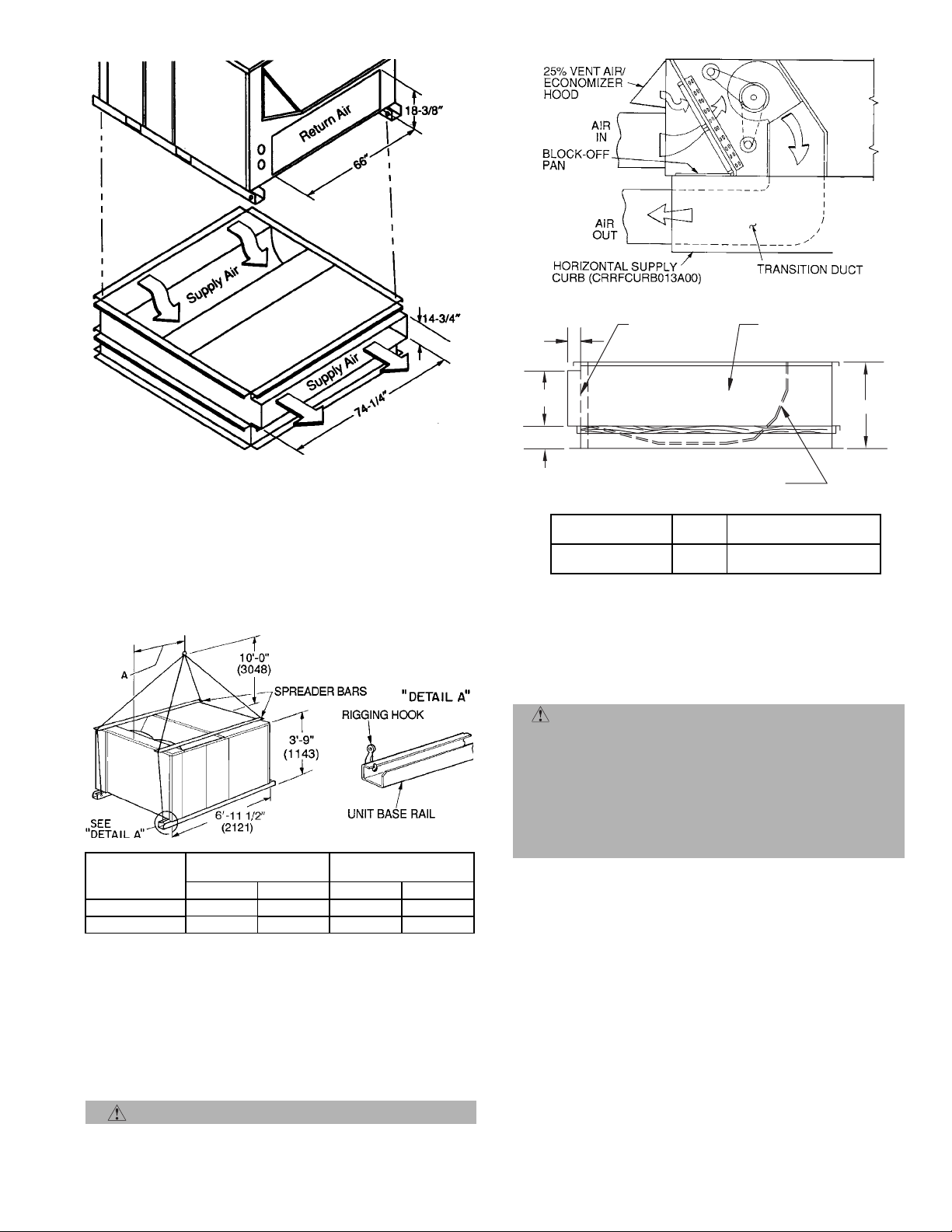
II. STEP 2 — RIG AND PLACE UNIT
Inspect unit for transportation damage. File any claim with
transportation agency. Keep unit upright, and do not drop.
Use spreader bars over unit to prevent sl ing or cabl e damage.
Rollers may be used to move unit across a roof. Level by using
unit frame as a reference; leveling tolerance is ±
linear ft in any direction. See Fig. 1 for additional leveling tolerance information. Unit weight is shown in Table 1.
Four lifting holes are provided in ends of unit base rails as
shown in Fig. 3. Refer to rigging inst ructions on unit.
A. Positioning
Provide clearance around and above unit for airflow, safety,
and service access (Fig. 4 and 5).
Do not install unit in an indoor location. Do not locate air
inlets near exhaust vents or other sources of contaminated air .
Although unit is weatherproof, guard against water from
higher level runoff and overhangs.
B. Roof Mount
Check building codes for weight distribution requirements.
III. STEP 3 — FIELD FABRICATE DUCTWORK
Secure all ducts to buildi ng structure. Use flexible duct connectors between unit and ducts as required. Insulate and
weatherproof all external ductwo rk, join ts, and roof openings
with counter flashing and mastic in accordanc e with applicable codes.
Ducts passing through an unconditioned space must be insulated and covered with a vapor barrier.
The 542J units with electric heat requi r e a 1-in. clearance for
the first 24 in. of ductwork.
1
/16 in. per lin-
1
/
in. per
16
Page 2
lb density.
2
/
1
AB
Deg. in. Deg. in.
DIMENSIONS (degrees and inches)*
ALL .28 .45 .28 .43
UNIT
below the unit discharge for units equipped with electric heaters.
1. Roof curb accessory is shipped disassembled.
2. Insulated panels: 1″ thick neoprene coated 1
3. Dimensions in ( ) are in millimeters.
NOTES:
4. Direction of airflow.
the indoor section, unit can only be pitched as shown.
5. Roof curb: 16 ga. (VA03-56) stl.
6. A 90 degree elbow must be installed on the supply ductwork
7. To prevent the hazard of stagnant water build-up in the drain pan of
DESCRIPTION
CURB
HEIGHT
Fig. 1 — Roof Curb Details
Standard Curbfor Units
Requiring High Installation
Side Supply and Return
Curb for High Installation
PKG. NO. REF.
CRRFCURB010A00 1′-2″ (305) Standard Curb 14″ High
CRRFCURB011A00 2′-0″ (610)
CRRFCURB012A00 2′-0″ (610)
—2—
Page 3
3 1/2"
2" X 1/4
SUPPORT TYP.
STITCH WELDED
FULLY INSULATED
SUPPLY PLENUM
1" INSULATION
1 1/2 # DENSITY,
STICK PINNED & GLUED
NOTE: CRRFCURB013A00 is a fully factory preassembled horizontal
adapter and includes an insulated transition duct. The pressure drop
through the adapter curb is negligible.
For horizontal return applications: The power exhaust and barometric
relief dampers must be installed in the return air duct.
Fig. 2 — Horizontal Supply/Return Adapter Installation
MAXIMUM
UNIT 542J
150 1895 860 3-1 948
180 2205 1000 3-6 1059
NOTES:
1. Dimensions in ( ) are in millimeters.
2. Refer to Table 1 for unit operating weights.
3. Remove boards at ends of unit and runners prior to rigging.
4. Rig by inserting hooks into unit base rails as shown. Use corner
post from packaging to protect coil from damage. Use bumper
boards for spreader bars.
5. Weights do not include optional EconoMi$erIV. See Table 1 for
EconoMi$erIV weight.
6. Weights given are for aluminum indoor coil plate fins and copper
outdoor coil plate fins. Weights of other metal combinations are
listed in Table 1.
SHIPPING WEIGHT
lb kg ft-in. mm
DIMENSION A
CAUTION: All panels must be in place when rigging.
Fig. 3 — Rigging Details
14 3/4"
6"
ACCESSORY
PACKAGE NO.
CRRFCURB013A00
12" WIDE STANDING
SEAM PANELS
CURB
HEIGHT
1′-11″
(584)
DESCRIPTION
Pre-Assembled, Horizontal
Adapter Roof Curb
23"
Outlet grilles must not lie directly below unit discharge.
NOTE: A 90-degree elbo w must be provid ed in the du ctwork
to comply with UL (Underwriters Laboratori es ) co d e s f or use
with electric heat.
WARNING: For vertical supply and return units,
tools or parts could drop into ductwork and cause an
injury. Insta ll a 90-de gree t urn in th e return ductwor k
between the unit and the conditioned space. If a
90-degree elbow cannot be installed, then a grille of
sufficient strength and density should be installed to
prevent objects from falling into the conditioned space.
Due to electric heater, supply duct will require
90-degree elbow.
IV. STEP 4 — MAKE UNIT DUCT CONNECTIONS
Unit is shipped for thru-the-bottom duct connections. Ductwork openings are shown in Fig. 6. Field-fabricated concentric ductwork may be connected as shown in Fig. 7 and 8.
Attach all ductwork to roof curb and roof curb basepans.
Refer to installation instructions shipped with accessory roof
curb for more information.
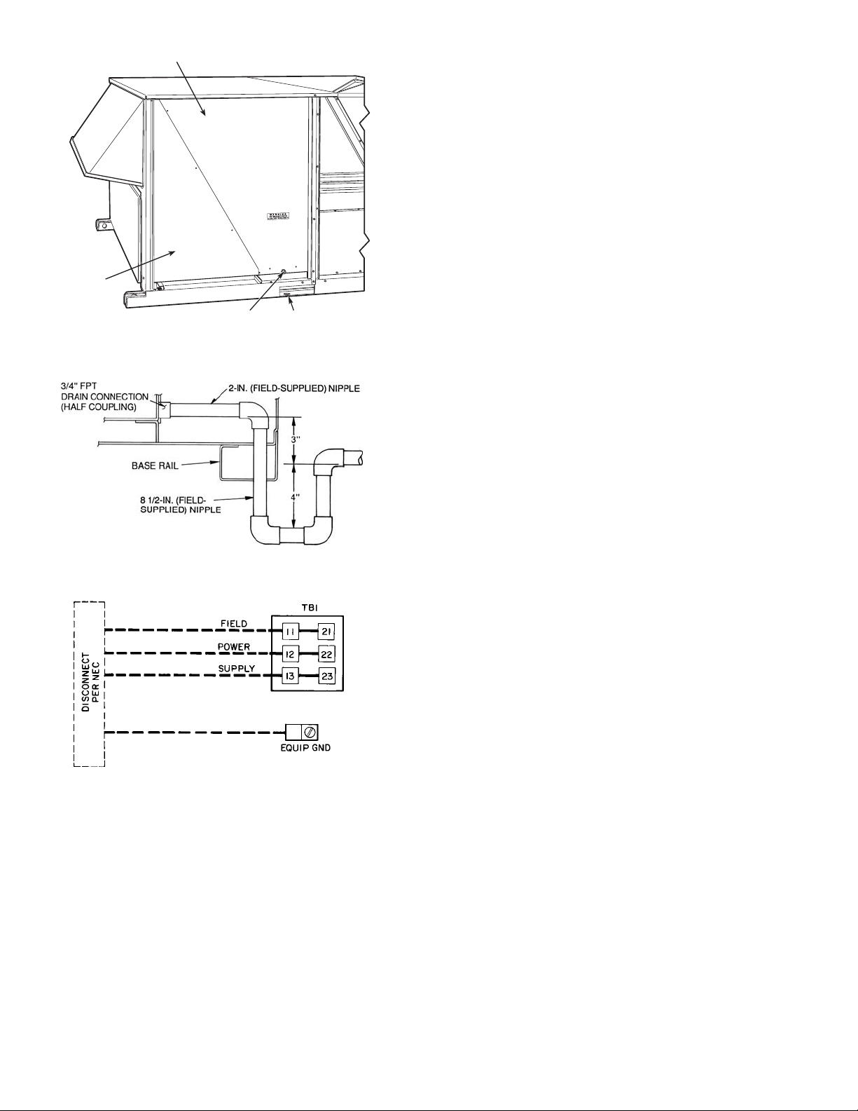
V. STEP 5 — TRAP CONDENSATE DRAIN
See Fig. 4 or 5 and 9 for drain location. Plug is provided in
drain hole and must be removed when unit is operating. One
3
/4-in. half coupling is provided inside unit indoor air section
for condensate drain connection. An 81/2 in. x 3/4-in. diameter
nipple and a 2-in. x
3
/4-in. diameter pipe nipple are coupled
to standard 3/4-in. diameter elbows to provide a straight path
down through holes in unit base rails (see Fig. 10). A trap at
least 4-in. deep must be used.
—3—
Page 4
Table 1 — Physical Data
UNIT SIZE 542J 150 180
NOMINAL CAPACITY (tons) 12
1
/
2
15
OPERATING WT (lb)
Al/Al* 1615 1925
Al/Al Coated* 1615 1925
Unit Al/Cu* 1745 2075
Cu/Cu* 1815 2165
Electric Heat 65 65
EconoMi$erIV 90 90
Roof Curb† 200 200
COMPRESSOR Semi-Hermetic
Type (Number) 06D-328 (1) 06D-818 (2)
Cylinders 64
Oil Change (oz.) (each circuit) 115 88
REFRIGERANT TYPE R-22
Charge (lb)
System 1 26.0 16.5
System 2 — 16.5
3
OUTDOOR COIL
Rows 33
/8 in., Internally Grooved Copper T ubes, Aluminum or Copper Lanced Fins
Fins/in. 15 15
Total Face Area (sq ft) 21.7 21.7
OUTDOOR FAN Propeller Type, Direct Drive
Nominal Cfm 9,000 9,000
Number...Diameter (in.) 3...22 3...22
Motor Hp (1075 rpm)
Watts Input (Total) 1090 1090
INDOOR CO IL
Expansio n D ev i c e Fixed Orifice
3
/8 in., Internally Grooved Copper Tubes, Aluminum or Copper Lanced Fins, Face Split
1
/
2
1
/
2
Rows 33
Fins/in. 15 15
Total Face Area (sq ft) 17.5 17.5
INDOOR FAN Centrifugal, Adjustable Pitch Belt Drive
Quantity...Size (in.)
Nominal Cfm 5000 6000
2...10 x 10 2...12 x 12
Maximum Continuous Bhp 4.25 5.90
Fan Rpm Range 862-1132 799-1010
Maximum Allowable Rpm 1550 1550
Motor Pulley Pitch Diameter (in.) 3.1/4.1 3.7/4.7
Fan Pulley Pitch Diameter (in.)
Belt, Quantity...Type...Length (in.) 1...BX...42 1...BX...46
Pulley Center Line Distance (in.) 13.5-15.5 13.3-14.8
Speed Change Per Turn (rpm)
6.0 11.4
54 42
Pulley Maximum Full Turns 6** 6**
Factory Pulley Turns Setting 33
Factory Speed Setting (rpm) 1024 926
Fan Shaft Diameter (in.)
Motor Hp (Service Factor) 3.7 (1.15) 5.0 (1.15)
Motor Frame Size 56H 184T
Motor Efficiency 0.84 0.84
3
/
1
16
17/
16
HIGH-PRESSURE SWITCH
Cutout (psig) 426
Reset (psig) 320
LOW-PRESSURE/LOSS-OF-CHARGE
SWITCH
Cutout (psig) 7
Reset (psig) 22
AIR INLET SCREENS Cleanable
Economi zer, Quantity...Size (in.)
RETURN-AIR FILTERS (TYPE) 10% Efficient — 2-in. Throwaway Fiberglass
Quantity...Size (in.)
DEFROST THERMOSTAT
Defrost Time 30 min (Adjustable to 50 or 90 min)
2...20 x 25 x 1
1...20 x 20 x 1
4...20 x 20 x 2
4...16 x 20 x 2
Closes (F) 28
Opens (F) 65
LEGEND
Al — Aluminum
Cu — Copper
*Indoor coil fin material/outdoor coil fin material.
†Weight of 14 in. roof curb.
**Pulley cannot be run at 0 or
1
/2 turns open.
—4—
Page 5
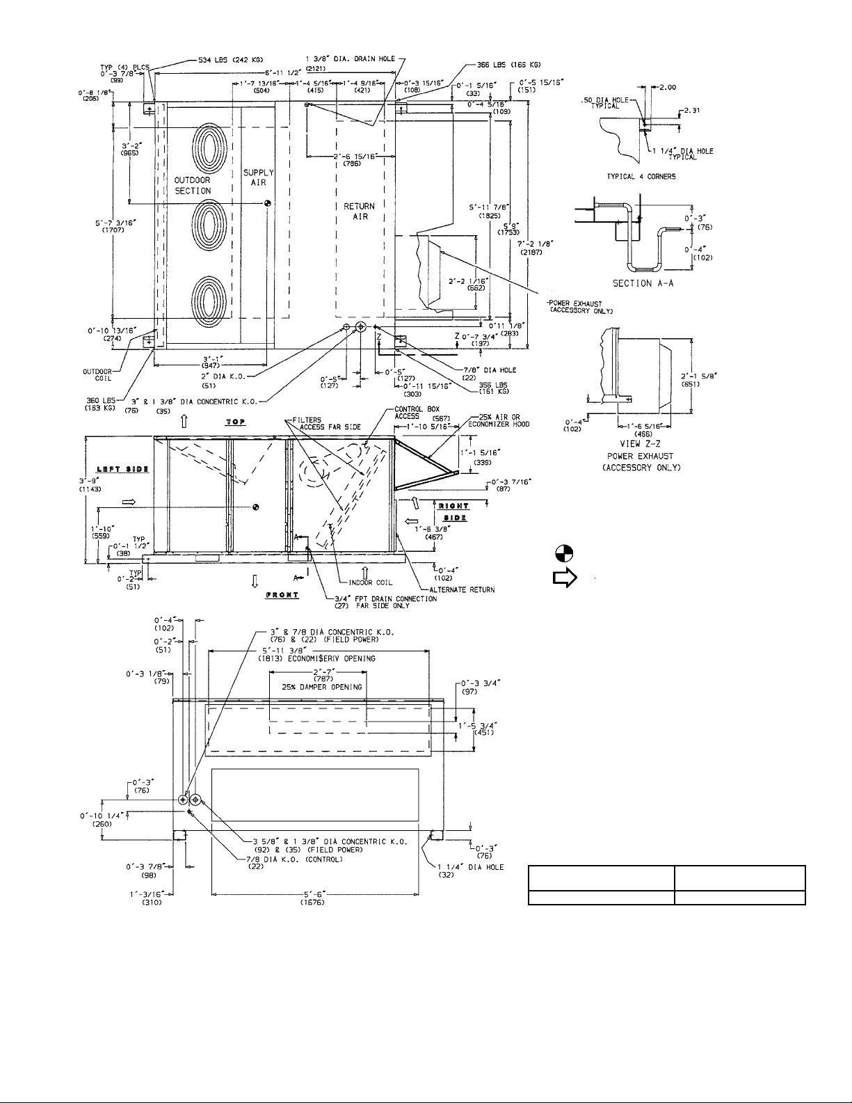
NOTES:
1. Refer to print for roof curb accessory dimensions.
2. Dimensions in ( ) are in millimeters.
3. Center of Gravity.
4. Direction of airflow.
5. Ductwork to be attached to accessory roof curb
only.
6. Minimum clearance:
•Rear: 7′-0″ (2 134) for coil removal. This dimension
can be reduced to 4′-0″ (1219) if conditions per mit
coil removal from the top.
• Left side: 4′-0″ (1219) for proper outdoor coil airflow.
• Front: 4′-0″ (1219) for control box access.
• Right side: 4′-0″ (1219) for proper operation of
damper and power exhaust (if so equipped).
• Top: 6′-0″ (1829) to assure proper outdoor fan
operation.
• Local codes or jurisdiction may prevail.
7. With the exception of clearance for the outdoor coil
and the damper/power exhaust as stated in note
no. 6, a removable fence or barricade requires no
clearance.
8. Dimensions are from outside of cor ner post. Allow
5
/
″ (8) on each side for top cover drip edge.
0′-
16
9. A 90 degree elbow must be installed on the supply
ductwork below the unit discharge for units
equipped with electric heat.
STANDARD UNIT
WEIGHT
ECONOMI$ERIV
WEIGHT
1615 lb (733 kg) 90 lb (41 kg)
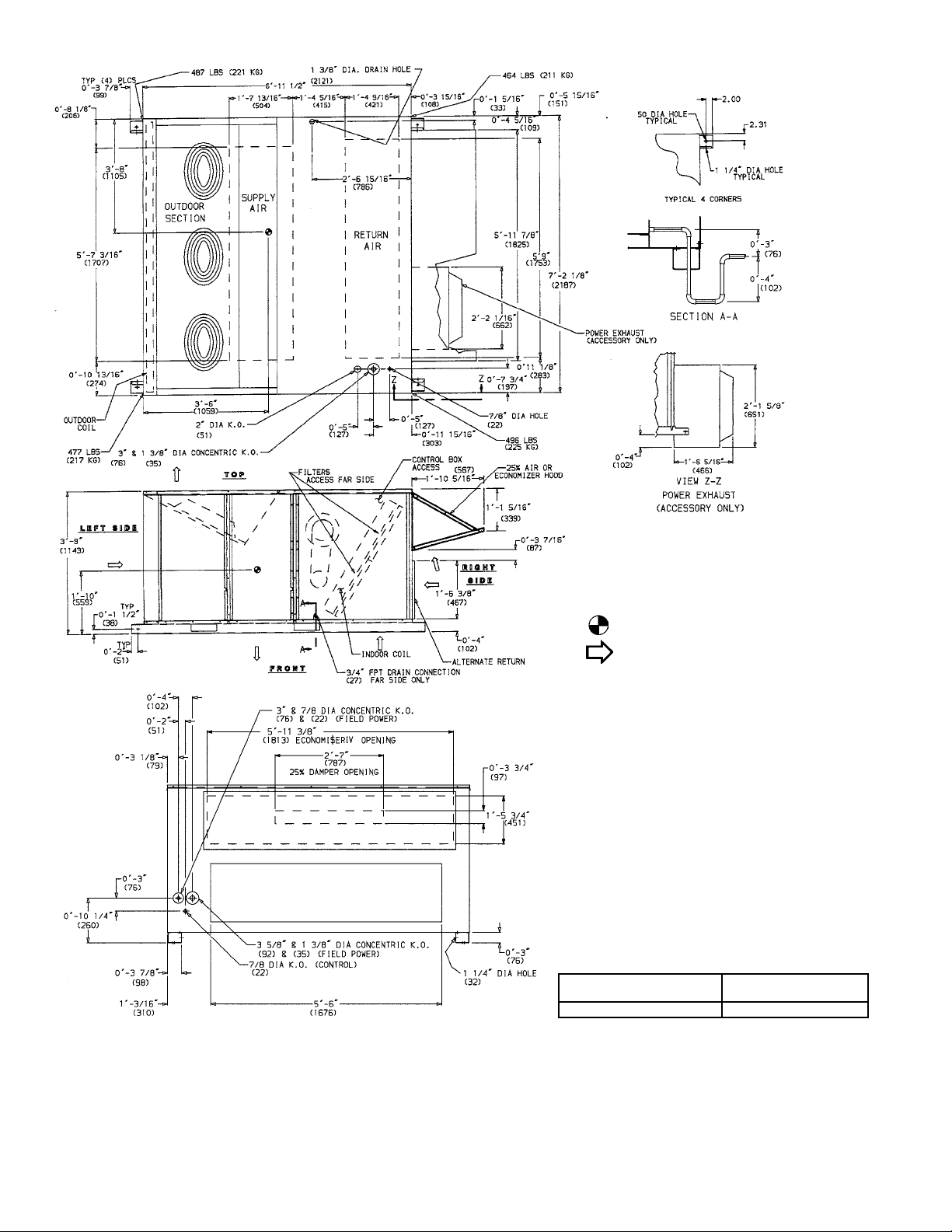
Fig. 4 — Base Unit Dimensions — 542J150
—5—
Page 6
NOTES:
1. Refer to print for roof curb accessory dimensions.
2. Dimensions in ( ) are in millimeters.
3. Center of Gravity.
4. Direc tion of airflow.
5. Ductwork to be attached to accessory roof curb
only.
6. Minimum clearance:
• Rear: 7′-0″ (2134) for coil removal. This dimension
can be reduced to 4′-0″ (1219) if conditions per mit
coil removal from the top.
• Left side: 4′-0″ (1219) for proper outdoor coil airflow.
•Front: 4′-0″ (1219) for control box access.
• Right side: 4′-0″ (1219) for proper operation of
damper and power exhaust (if so equipped).
• Top: 6′-0″ (1829) to assure proper outdoor fan
operation.
• Local codes or jurisdiction may prevail.
7. With the exception of clearance for the outdoor coil
and the damper/power exhaust as stated in note
no. 6, a removable fence or barricade requires no
clearance.
8. Dimensions are from outside of corner post. Allow
5
/
″ (8) on each side for top cover drip edge.
0′-
16
9. A 90 degree elbow must be installed on the supply
ductwork below the unit discharge for units
equipped with electric heat.
STANDARD UNIT
WEIGHT
ECONOMI$ERIV
WEIGHT
1925 lb (874 kg) 90 lb (41 kg)
Fig. 5 — Base Unit Dimensions — 542J180
—6—
Page 7
NOTE: Do not drill in this area, as damage to basepan may result in
water leak.
Fig. 6 — Air Distribution — Thru-the-Bottom
(542J180 Shown)
VI. STEP 6 — MAKE ELECTRIC CONNECTIONS
A. Field Power S upply
Unit is factory wired for voltage shown on nameplate.
When installing units, provide a disconnect of adequate size
per NEC (National Electrical Code) requirements (Table 2).
All field wiring must comply with NEC and local
requirements.
Route power lines through control box access panel or unit
basepan (Fig. 4 and 5) to connections as shown on unit wiring diagram and Fig. 11.
Transformers no. 1 and 2 are wired for 230-v unit. If 208/
203-v unit is to be run with 208-v power supply, the transformers must be rewired as follows:
1. Remove cap from red (208 v) wire.
2. Remove cap from orange (230 v) spliced wire.
3. Replace orange wire with red wire.
4. Recap both wires.
IMPORTANT: BE CERTAIN UNUSED WIRES ARE
CAPPED. Failure to do so may damage the transformers.
Operating voltage to compressor must be within voltage
range indicated on unit nameplate. On 3-phase units, voltages between phases must be balanced within 2% and the
current must be balanced w ith in 10%.
Use the following formula to determine the percentage of
voltage imbalance.
Perce nt ag e of Voltage Imbalance
NOTE: Do not drill in this area, as damage to basepan may result in
water leak.
Fig. 7 — Concentric Duct Air Distribution
(542J180 Shown)
Shaded area indicates block-off panels.
NOTE: Dimensions A, A′ and B, B′ are obtained from field-supplied
ceiling diffuser.
Fig. 8 — Concentric Duct Details
= 100 x
max voltage deviation from average voltage
average voltage
EXAMPLE: Supply voltage is 460-3-60.
AB = 452 v
BC = 464 v
AC = 455 v
Average Voltage =
455 + 464 + 455
1371
=
3
3
= 457
Determine maximum deviation from average voltage:
(AB) 457 – 452 = 5 v
(BC) 464 – 457 = 7 v
(AC) 457 – 455 = 2 v
Maximum deviation is 7 v.
Determine the percent voltage imbal ance:
Percentage of Voltage Imbalance= 100 x
7
457
= 1.53%
This amount of phase imbalance is satisfactory as it is below
the maximum allowable 2%.
IMPORTANT: If the supply voltage phase imbalance is
more than 2%, contact your local electric utility company
immediately.
Unit failure as a res ult of ope ra tio n o n imp ro per line volt age
or excessive phase imbalance constitutes abuse and may
cause damage to electrical components.
—7—
Page 8
INDOOR FAN MOTOR ACCESS
FILTER
ACCESS
3/4" FPT DRAIN
CONNECTION
1-3/8"
DRAIN HOLE
Fig. 9 — Condensate Drain Details
Fig. 10 — Condensate Drain Piping Details
LEGEND
EQUIP GND — Equipment Ground
kcmil — Thousand Circular Mils
NEC — National Electrical
TB — Terminal Block
NOTE: The maximum wire size for TB1 is 350 kcmil f or all unit v olt ages.
Fig. 11 — Field Power Wiring Connections
B. Field Control Wiring
Install a Bryant-approved accessory thermostat assembly
according to th e installation instru ctions included with the
accessory. Refer to unit Price Pages or contact your
local Bryant representative for more information. Locate
thermostat assembly on a solid wall in the conditioned space
to sense average temperature.
Route thermostat cable or equivalent single leads of no. 18
AWG (American Wire Gage) colored wire from subbase te rminals through conduit in unit to low-voltage connections as
shown on unit label wiring diagram and in Fig. 12.
NOTE: For wire runs up to 50 ft, use no. 18 AWG insulated
wire (35 C minimum). For 50 to 75 ft, use no. 16 AWG insulated wire (35 C minimum). For over 75 ft, use no. 14 AWG
insulated wire (35 C minimum). All wi re larger than no. 18
AWG cannot be directly connected to the thermostat and will
require a junction box and splice at the thermostat.
Set heat anticipator settings as indicated in T able 3. Settings
may be changed sligh tly to pr ovide a great er degree of comfort for a particular installation.
C. Optional Non-Fused Disconnect
On units with the optional non-fused disconnect, incoming
power will be wired into the disconnect switch. Refer to
Fig. 13 for wiring for 100 and 200 amp disconnect switches.
Units with an MOCP (maximum overcurrent protection)
under 100 will use the 100 amp disconnect switch. Units
with an MOCP over 100 will use the 200 amp disconnect
switch. Refer to the applicable disconnect wiring diagram.
To prevent breakage during shipping, the disconnect handle
and shaft are shipped and packaged inside the unit control
box. Install the disconnect handle before unit operation.
To install the handle and shaft, perform the following
procedure:
1. Open the control box door and r e mo ve t he handle and
shaft from shipping location.
2. Loosen the Allen bolt located on the disconnect
switch. The bolt is locat ed on the sq uare hole a nd is
used to hold the shaft in place. The shaft cannot be
inserted until the Allen bolt is moved.
3. Insert the disconnect shaft into the square hole on
the disconnect switch. The end of the shaft is specially cut and the shaft can only be inserted in the
correct orientation.
4. Tighten the Allen bolt to lock the shaft into position.
5. Close the control bo x door.
6. Attach the handle to the external access door with
the two screws provided. When the handle is in
the ON position, the handle will be vertical. When
the handle is in the OFF position, the handle will be
horizontal.
7. Turn the handle to the OFF position and close the
door. The handle should fit over th e end of the shaf t
when the door is closed.
8. The handle must be in the OFF position to open the
control box door.
D. Optional Convenience Outlet
On units with optional convenience outlet, a 115-v GFI
(ground fault interrupt) convenience outl et rece ptacle is pr ovided for field wiring. Field wiring should be run thro ugh th e
7
/8-in. knockout provided in the basepan near the return air
opening.
—8—
Page 9
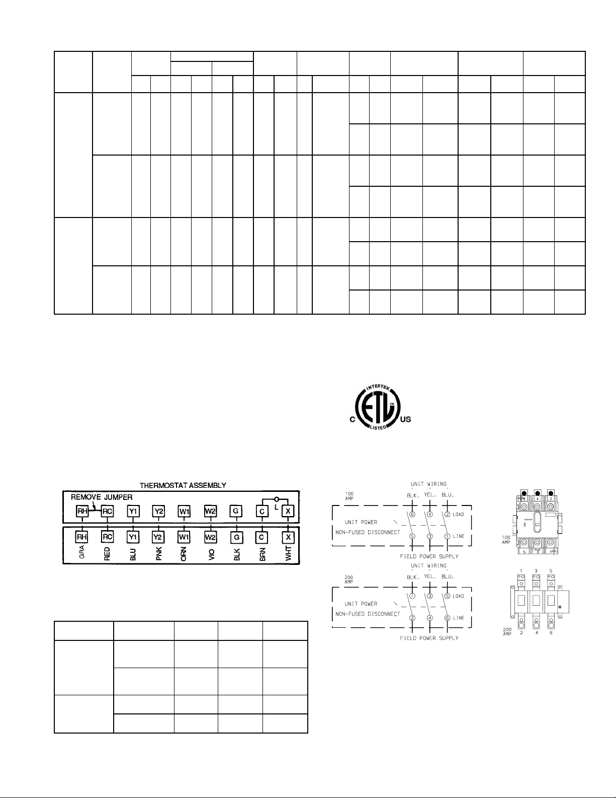
Table 2 — Electrical Data
UNIT
542J
150
180
VOLTAGE
(3 Ph,
60 Hz)
208/230 187 253 39.7 228 — — 3 1.7 3.7 10.5/10.5
208/230 187 253 28.2 160 28.2 160 3 1.7 5 15.8/15.8
VOLTAGE
RANGE
Min Max RLA LRA RLA LRA Qty
460 414 508 19.9 114 — — 3 0.8 3.7 4.8
460 414 508 14.1 80 14.1 80 3 0.8 5 7.9
LEGEND
FLA — Full Load Amps
HACR — Heating, Air Conditioning and Refrigeration
LRA — Locked Rotor Amps
MCA — Minimum Circuit Amps
MOCP — M aximum Overcurrent Protection
NEC — National Electrical Code
RLA — Rated Load Amps
*Heater capacity (kW) is based on heater voltage of 208 v, 240 v, and
480 v. If po wer distribution voltage to unit varies from rated heater voltage, heater kW will vary accordingly.
†Fuse or HACR circuit breaker. This is the maximum size permissible;
smaller fuse size may be used where conditions permit.
COMPRESSOR OUTDOOR
No. 1 No. 2
FAN
MOTOR
FLA
(ea)
INDOOR FAN
MOTOR
Hp FLA FLA LRA FLA kW MCA MOCP† RLA LRA
POWER
EXHAUST
——
4.6 18.8
——
2.3 6.0
——
4.6 18.8
——
2.3 6.0
ELECTRIC HEAT* POWER SUPPLY
—/— —/— 65/ 65 100/100 64/ 64
39/ 45 14/19 114/122 125/150 64/ 64
72/ 82 26/34 155/168 175/175 94/107
117/135 42/56 211/200 225/225 147/167
—/— —/— 70/ 70 100/100 69/ 69
39/ 45 14/19 119/126 125/150 69/ 69
72/ 82 26/34 159/173 175/175 100/112
117/135 42/56 216/205 225/225 152/173
— — 32 50 31
18 15 54 60 31
39 32 81 90 50
66 55 98 110 82
— — 34 50 34
18 15 57 70 34
39 32 83 90 53
66 55 100 110 84
—/— —/— 84/ 84 110/110 89/ 89
117/135 42/56 231/219 250/225 153/173
—/— —/— 89/ 89 110/110 94/ 94
117/135 42/56 235/224 250/225 158/179
— — 42 50 44
66 55 108 110 85
— — 44 50 47
66 55 110 125 88
DISCONNECT
SIZING
387/387
406/406
189
195
499/48572/ 82 26/34 174/187 175/200 101/112
518/50472/ 82 26/34 179/191 200/200 106/118
23839 32 91 100 54
24439 32 93 100 57
NOTES:
1. In compliance with NEC requirements for multimotor and combination load equipment (refer to NEC Articles 430 and 440), the overcurrent protective device for the unit shall be fuse or HACR
breaker. The Canadian units may be fuse or circuit breaker.
2. MCA calculation for units with electric heaters over 50 kW = (1.25 x
IFM amps) + (1.00 x heater FLA).
Fig. 12 — Field Control Thermostat Wiring
Table 3 — Heat Anticipator Settings
UNIT 542J
150
180
UNIT
VOLTAGE
208/230-3-60
460
208/230
460
HEATER
kW
14/19 .40 —
26/34 .40 .40
42/56 .66 .40
15 .40 —
32 .40 .40
55 .40 .66
26/34 .40 .66
42/56 .66 .40
32 .40 .40
55 .40 .66
6T3 4T2 2T1 LOAD
5L3 3L2 1L1 LINE
STAGE 1 STAGE 2
NOTE: The disconnect takes the place of TB-1 as shown on the unit
wiring diagram label and the component arrangement label.
Fig. 13 — Optional Non-Fused Disconnect Wiring
—9—
Page 10
VII. STEP 7 — MAKE OUTDOOR-AIR INLET ADJUSTMENTS
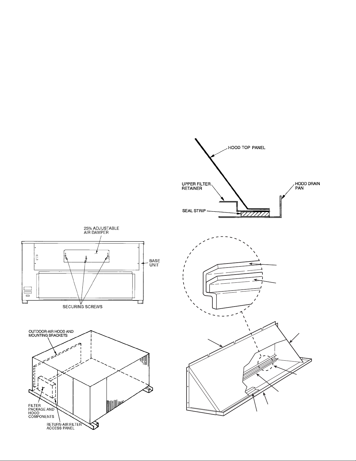
A. Manual Outdoor-Air Damper
All units (except those equipped with a factory-installed
EconoMi$erIV ) h ave a ma nual out door-air damper to provide
ventilation air . Damper can be preset to admit up to 25% outdoor air into return-air compartment. To adjust, loosen
securing screws and move damper to desired setting. Then
retighten screws to secure damper (Fig. 14).
VIII. STEP 8 — INSTALL OUTDOOR-AIR HOOD
IMPORTANT: If the unit is equipped with the optional
EconoMi$erIV component, move the outdoor-air temperature sensor prior to installing the outdoor-air hood. See the
Optional EconoMi$erIV section for more information.
The same type of factory-installed hood is used on units with
25% air ventilation and units with an EconoMi$erIV.
NOTE: The hood top panel, upper and lower filter retainers,
hood drain pan, and filter support bracket are secured opposite the outdoor coil end of the unit. The screens, hood side
panels, remaining section of filter support bracket, seal strip,
and all other hardware ar e in a package located inside t he
return-air filter access panel (Fig. 15).
1. Attach seal strip to upper filter retainer. See Fig. 16.
2. Assemble hood top panel and side panels, upper filter
retainer, and hood drain pan (Fig. 17).
3. Secure lower filter retainer and long section of filter
support bracket to unit. See Fig. 17.
4. Loosen sheet metal screws for base unit top panel
located above o utdoor-air inlet opening, and remove
screws for hood side panels located on the sides of the
outdoor-air inlet opening.
5. Match notches in hood top panel to unit top panel
screws. Insert hood flange between unit top panel
flange and unit. Tighten screws.
6. Hold hood side panel flanges flat against unit, and
install screws removed in Step 4.
7. Insert outdoor-air inlet screens and spacer in channel
created by lower filter retainer and filter support
bracket.
8. Attach remaining short section of filter support
bracket.
IX. STEP 9 — INSTALL ALL ACCESSORIES
After all the factory-installed options have been adjusted,
install all field-instal led accessories. Refer to the accessory
installation instructions included with each accessory.
Fig. 14 — 25% Outdoor-Air Section Details
HOOD TOP
PANEL
Fig. 16 — Seal Strip Location
(Air Hood Cross-Sectional View)
LOWER FILTER
RETAINER
FILTER SUPPORT
BRACKET
FILTER SUPPORT
BRACKET
HOOD SIDE
PANELS (2)
LOWER
FILTER
RETAINER
Fig. 15 — Outdoor-Air Hood Component Location
HOOD DRAIN PAN
UPPER FILTER RETAINER
NOTE: The outdoor-air hood comes with a baffle which is not used on
these units. Discard the baffle.
Fig. 17 — Outdoor-Air Hood Details
—10—
Page 11
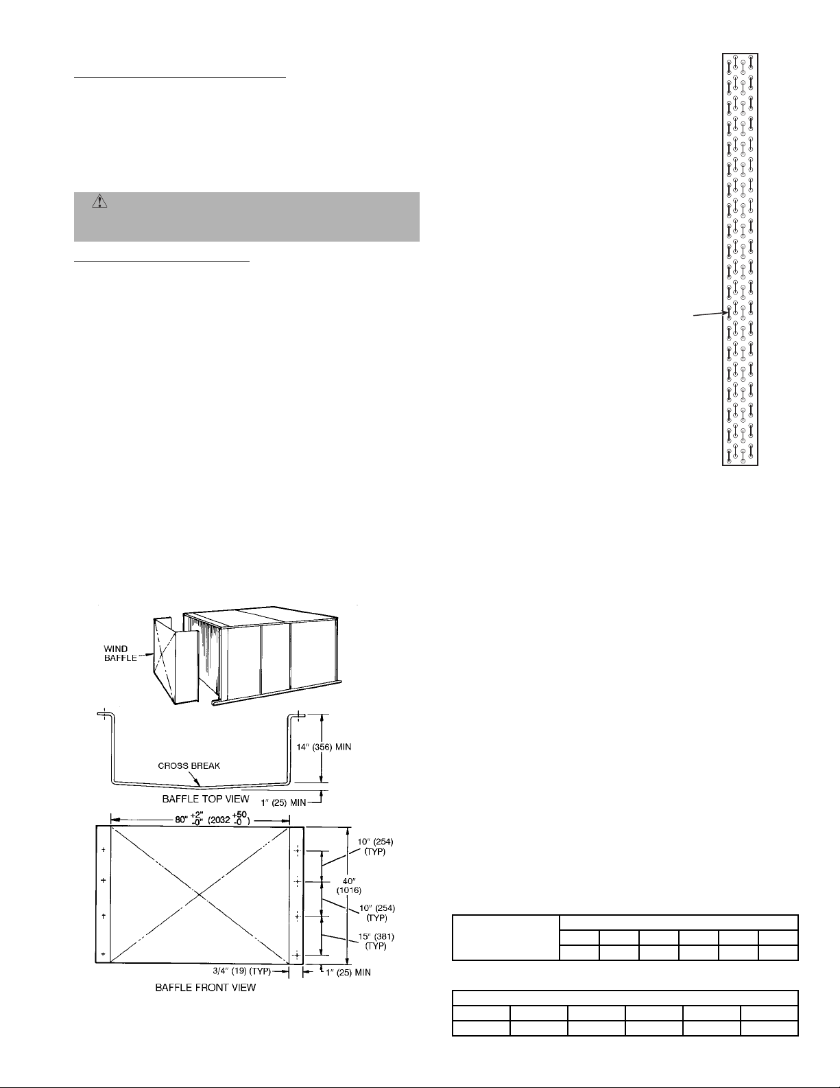
A. Motormaster® I Control Installation
Install Field-Fabricated Wind Baffles
Wind baffles must be field-fabricated for all units to ensure
proper cooling cycle operation at low ambient temperatures.
See Fig. 18 for baffle details. Use 20-gage, galvanized sheet
metal, or similar corrosion-resistant metal for baffles. Use
field-supplied screws to at tach baffles t o unit. Screws shou ld
1
be
/4-in. diameter and 5/8-in. long. Drill required screw holes
for mounting baffles.
CAUTION: To avoid damage to the refrigerant coils
and electrical components, use recommended screw sizes
only. Use care when drilling holes.
Install Motormaster I Controls
Only one Motormaster I control is required per unit. The
Motormaster I control must be used in c onjunction with the
accessory 0° F low ambien t kit (purchased separately). The
Motormaster I device controls outdoor fan no. 1 while ou tdoor fans no. 2 and 3 are sequenced off by the accessory 0° F
low ambient kit.
Accessory 0° F Low Ambient K it — Install the accessory 0° F
low ambient kit per instruction supplied with accessory.
Sensor Assembl y — Install the sensor assembly in the location shown in Fig. 19.
Motor Mount — To ensure proper fan height, replace the
existing motor mount with the new motor m ount provided
with accessory .
Transfor mer (460-V Units On ly) — On 460-volt units a transformer is required. The transformer is provided with the
accessory and must be field-installed.
Motormaster I Control — Recommended mounting location
is on the inside of the panel to the left of the control box. The
control should be mounted on the inside of the panel, vertically, with leads protruding from bottom of extrusion.
MOTORMASTER
SENSOR
LOCATION
NOTES:
1. All sensors are located on the eighth
hairpin up from the bottom.
2. Field-installed tubing insulation is
required to be installed over the TXV
bulb and capillary tube for proper
operation at low ambients. Tubing
insulation is only required on the portion of suction line located between
indoor and outdoor section.
HAIRPIN END
Fig. 19 — Motormaster I Sensor Locations
X. STEP 10 — ADJUST FACTORY-INSTALLED OPTIONS
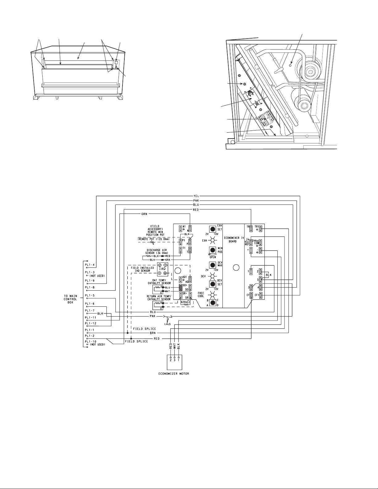
A. Optional EconoMi$erIV
See Fig. 20 and 21 for EconoMi$erIV component locati ons.
NOTE: These instructions are for installing the optional
EconoMi$erIV only. Refer to the accessory EconoMi$erIV or
EconoMi$er2 installation instructions when field in stalling an
EconoMi$erIV or EconoMi$er2 accessory.
To complete installation of t he optional EconoMi$erIV, perform the following procedure.
1. Remove the EconoMi$er IV hood. Refer to Step 8 —
Install Outdoor-Air Hood on page 10 for info rmation
on removing and in stalling the outdoor-air hood.
2. Relocate outdoor air temperature sensor from shipping position to operation pos ition on EconoMi $erIV.
See Fig. 20.
IMPORTANT: Failure to relocate the sensor w ill res ult in the
EconoMi$erIV not operating properly.
3. Re-install economizer hood.
4. Install all EconoMi$erIV accessories. EconoMi$erIV
wiring is shown in Fig. 22.
Outdoor air leakage is shown in Table 4. Return air pressure
drop is shown in Tabl e 5.
Table 4 — Out door Air Damper Leakage
NOTE: Dimensions in ( ) are in mm.
Fig. 18 — Wind Baffle Details
DAMPER STATIC PRESSURE (in. wg)
0.2 0.4 0.6 0.8 1.0 1.2
LEAKAGE (cfm) 35 53 65 75 90 102
Table 5 — Return Air Pressure Drop (in. wg)
CFM
4500 5000 5400 6000 7200 7500
0.040 0.050 0.060 0.070 0.090 0.100
—11—
Page 12
SCREWS
ECONOMI$ERIV
FRAME
TOP
SCREWS
OUTDOOR AIR
TEMPERATURE SENSOR
(INSTALLED OPERATION
POSITION)
LOW TEMPERATURE
COMPRESSOR
LOCKOUT SWITCH
ECONOMI$ERIV
SUPPLY AIR
TEMPERATURE SENSOR
LOCATION
Fig. 20 — EconoMi$erIV Component Locations —
End View
ACTUATOR
CONTROLLER
FLANGE
AND SCREWS
(HIDDEN)
1
R
T
R
T
c
a
V
4
2
M
O
C
4
2
_
c
a
V
T
O
H
H
X
E
+
t
e
S
V
0
2
1
V
2
1
1
N
5
N
n
H
i
X
M
E
s
o
P
4
n
P1
e
p
P
O
3
V
C
1
D
x
a
EF
T1
M
T
V
0
1
EF
V
2
V
C
D
V
t
C
e
D
S
V
1
0
Q
1
A
Q
A
V
2
+
e
O
e
r
S
C
F
l
o
O
o
S
C
B
D
+
R
S
A
R
S
Fig. 21 — EconoMi$erIV Component Locations —
Side View
DCV — Demand Controlled Ventilation
LEGEND
IAQ — Indoor Air Quality
LALS— Low Temperature Compressor
Lockout Switch
OAT — Outdoor-Air Temperature
POT — Potentiometer
Potentiometer Default Settings:
Power Exhaust Middle
Minimum Pos. Fully Closed
DCV Max. Middle
DCV Set Middle
Enthalpy C Setting
Fig. 22 — EconoMi$erIV Wiring
NOTES:
1. 620 ohm, 1 watt 5% resistor should be rem oved only when using differential
enthalpy or dry bulb.
2. If a separate field -supplied 24 v transform er is used for the IAQ sensor power
supply, it cannot have the secondary of the transformer grounded.
3. For field-installed remote minimum position POT, remove black wire jumper
between P and P1 and set control minimum position POT to the minimum
position.
—12—
Page 13

B. EconoMi$erIV Standard Sensors
Outdoor Air Temperature (OAT) Sensor
The outdoor air temperature sensor (HH57AC074) is a 10 to
20 mA device used to measure the outdoo r-air temperature.
The outdoor-air temperature is used to determine when the
EconoMi$erIV can be used for free cooling. The sen sor must
be field-relocat ed. See Fig. 20. The operat ing range of temperature measurement is 40 to 100 F.
Supply Air Temperature (SAT) Sensor
The supply air temperature sensor is a 3 K thermistor
located at the inlet of the indoor fan. See Fig. 21. This sensor
is factory installed. The operating range of temperature
measurement is 0° to 158 F. See Table 6 for sensor temperature/resistance values.
The temperature sensor l ooks like an eyelet terminal with
wires running to it. The sensor is located in the “crimp end”
and is sealed from moisture.
Low Temperature Compressor Lockout Switch
The EconoMi$erIV is equipped with an ambient tempera-
ture lockout switch located in the outdoor air stream which
is used to lockout the compressors below a 42 F ambient temperature. See Fig. 20.
Table 6 — Supply Air Sensor Temperature/
Resistance Values
TEMPERATURE (F) RESIST ANCE (ohms)
–58 200,250
–40 100,680
–22 53,010
–4 29,091
14 16,590
32 9,795
50 5,970
68 3,747
77 3,000
86 2,416
104 1,597
122 1,080
140 746
158 525
176 376
185 321
194 274
212 203
230 153
248 116
257 102
266 89
284 70
302 55
C. EconoMi$erIV Control Modes
Determine the EconoMi$erIV control mode before set up of the
control. Some modes of operation may require different sensors.
Refer to Table 7. The EconoMi$erIV is supplied from the factory
with a supply air temp erat ure sen sor, a low temperature compressor lockout switch, and an outdoor air temperature sensor.
This allows for operation of the EconoMi$erIV with outdoor air
dry bulb changeover control. Additional accessories can be
added to allow for different types of changeover control and
operation of the EconoMi$erIV and unit.
Outdoor Dry Bulb Changeover
The standard controller is shippe d from the factory config-
ured for outdoor dry bulb changeover control. The outdoor
air and su pply air temperature sensors are included as standard. For this control mode, the outdoor temperature is compared to an adjustable set point selected on the control. If the
outdoor-air temperature is above the set point, the
EconoMi$erIV will adjust the outdoor-air dampers to minimum position. If the outdoor-air temperature is below the set
point, the position of the outdoor-air dampers will be controlled to provid e fr ee co o lin g us ing out do or ai r. When in this
mode, the LED next to the free cooling set point potentiometer will be on. The changeover temp erature set poi nt is controlled by the free cooling set poi nt potentiomete r located on
the control. See Fig. 23. The scal e on the p otentio meter i s A,
B, C, and D. See Fig. 24 for the corresponding temp erature
changeover values.
Differential Dry Bulb Control
For differential dry bulb control the standard outdoor dry
bulb sensor is used in conjunction with an additional accessory return air sensor (part number CRTEMPSN002A00).
The accessory sensor must be mounted in the return
airstream. See Fig. 25.
In this mode of operation, the outdoor-air temperature is
compared to the return-air temperature and the lower temperature airstream is used for cooling. When using this mode
of changeover control, turn the free cooling/enthalpy set point
potentiometer fully clockwise to the D setting. See Fig. 23.
Table 7 — EconoMi$er IV Sensor Usage
ECONOMI$ERIV WITH OUTDOOR AIR
APPLICATION
Outdoor Air Dry Bulb None. The outdoor air dry bulb sensor is factory installed. CRTEMPSN002A00*
Differential Dry Bulb CRTEMPSN002A00* ( 2) CRTEMP S N002 A 00*
Single Enthalpy HH57AC078 None. The single enthalpy sensor is factory installed.
Differential Enthalpy
for DCV Control using a
CO
2
Wall-Mounted CO
for DCV Control using a
CO
2
Duct-Mounted CO
*CRENTDIF004A00 an d CRTEMPSN002A00 accessories are used on many different base units. As such, these kits may conta in parts that will not be need ed for
installation.
†CGCDXSEN004A00 is an accessory CO
**CGCDXASP001A00 is an accessory aspirator box required for duct-mounted applicatio ns.
Sensor
2
Sensor
2
sensor.
2
DRY BULB SENSOR
Accessories Required Accessories Required
HH57AC078
and
CRENTDIF004A00*
CGCDXSEN004A00
CGCDXSEN004A00†
and
CGCDXASP001A00**
ECONOMI$ERIV WITH SINGLE
ENTHALPY SENSOR
CRENTDIF004A00*
—13—
Page 14

Fig. 23 — EconoMi$erIV Controller Potentiometer
and LED Locations
19
LED ON
mA
18
17
16
15
14
13
12
11
10
9
40
45
LED OFF
50
D
LED ON
C
LED OFF
60
55
LED ON
B
LED OFF
70
75
65
LED ON
A
LED OFF
90
95
85
80
DEGREES FAHRENHEIT
Fig. 24 — Outside Air Temperature
Changeover Set Points
1
R
T
R
T
c
Va
4
2
OM
C
4
2
_
c
Va
T
H
O
X
H
E
t
+
e
S
V
10
2
V
2
1
N
1
N
5
n
i
XH
M
E
s
o
P
IAQ
SENSOR
1
P
4
en
P
p
O
V
3
C
D
x
1
T
1
a
F
M
E
T
V
0
1
F
E
V
2
V
C
D
V
C
et
D
S
V
0
Q1
1
A
Q
A
V
2
+
O
e
e
S
r
C
F
l
O
o
o
S
C
B
D
+
R
S
A
R
S
RETURN AIR
TEMPERATURE
OR ENTHALPY
SENSOR
Fig. 25 — Return Air Temperature or Enthalpy
Sensor Mounting Location
100
Outdoor Enthalpy Changeover
For enthalpy control, accessory enthalpy sensor (part num-
ber HH57AC078) is required. Replace the standard outdoor
dry bulb temperature sensor with the accessory enthalpy
sensor in the same mounting location. See Fig. 20. When the
outdoor air enthalpy rises above the outdoor enthalpy
changeover set point, the outdoor-air damper moves to its
minimum position. The outdoor enthalpy changeover set
point is set with the ou tdoor enthalpy set poi nt potentiometer on the EconoMi$er IV controller. The set points are A, B,
C, and D. See Fig. 26. The factory-installed 620-ohm jumper
must be in place across terminals SR and SR+ on the
EconoMi$erIV controller. See Fig. 23 and 27.
Differential Ent halpy Control
For differential enthalpy control, the EconoMi$er IV cont rolle r
uses two enthalpy sensors (HH57AC078 and
CRENTDIF004A00), one in the outside air and one in the
return airstream on the EconoMi$erIV frame. The
EconoMi$erIV controller compares t he outdoor air enthalp y to
the return air entha lpy to dete rmine Econo Mi$erIV use. The
controller s elects the lower enthal py air (return or outdoor)
for cooling. For example, when the outdoor air has a lower
enthalpy than the return air and is below the set point, the
EconoMi$erIV opens to bring in outdoor air for free c ooling.
Replace the standard outside air dry bulb temperature sensor with the acc essor y enth alpy senso r in th e same mou nting
location. See Fig. 20. Mount th e return air enthalpy sen sor
in the return airstream . See Fig. 25. The outdoor enthalpy
changeover set point is set with the outdoor enthalpy set
point potentiometer on th e EconoMi$erIV controller. When
using this mode of changeover control, turn the enthalpy set
point potentiometer fully clockwise to the D setting.
NOTE: Remove 620-ohm resistor if differential enthalpy sensor is installed.
Indoor Air Quality (IAQ) Sensor Input
The IAQ input can be used for demand control ventilation
control based on the level of CO2 measured in the sp ace or
return air duct.
Mount the accessory IAQ sensor according to manufacturer
specifica t io n s. The IAQ se n so r sh ould be wired to the AQ and
AQ1 terminals of the controller. Adjust the DCV potentiometers to correspond to the DCV voltage output of the indoor air
quality sensor at the user-determined set point. See Fig. 28.
If a separate field-supplied transformer is used to power the
IAQ sensor, the sensor must not be grounded or the
EconoMi$erIV control board will be damaged.
Exhaust Set Point Adjustment
The exhaust set point will determine when the exhaust fan
runs based on d am p er po sit i on ( if accessory powe r ex ha ust is
installed). The set point is modified with the Exhaust Fan
Set Point (EXH SET) potentiometer. See Fig. 23. The set
point represents the damper position above which the
exhaust fan will be turned on. When there is a call for
exhaust, the E con o Mi $er I V co ntro ller provides a 45 ± 15 sec ond delay before exhaust fan activation to allow the dampers
to open. This delay allows the damper to reach the appropriate position to avoid unnecessary fan overload.
—14—
Page 15

CONTROL
CURVE
4
1
2
1
A
B
C
D
1
6
1
CONTROL POINT
APPROX. °F (°C)
AT 50% RH
73 (23)
70 (21)
67 (19)
63 (17)
HA
NT
E
4
2
2
2
0
2
8
35
(2)
LPY
40
(4)
85
(29)90(32)95(35)
46
4
4
42
40
IR
8
3
Y A
6
DR
3
D
N
U
4
3
PO
R
32
E
P
TU
30
B
—
28
26
(16)
55
(13)
B
50
C
(10)
45
D
(7)
70
(21)
0
1
65
(18)
60
A
80
(27)
75
(24)
0
0
9
80
70
0
6
50
40
RELA
3
100
105
(38)
110
(41)
(43)
)
%
(
IDITY
IVE HUM
T
0
20
0
1
N1
P1
T1
AQ1
SO+
SR+
A
B
C
D
35
40
45
50
55
60
65
70
75
80
(2)
(4)
(7)
(10)
(13)
(16)
(18)
(21)
(24)
85
(27)
(29)90(32)95(35)
100
(38)
105
(41)
110
(43)
HIGH LIMIT
CURVE
APPROXIMATE DRY BULB TEMPERATURE— °F (°C)
Fig. 26 — Enthalpy Changeover Settings
CO SENSOR MAX RANGE SETTING
EXH
2V 10V
EXH
Open
2V 10V
DCV
2V 10V
Free
Cool
B
A
Min
Pos
DCV
Max
DCV
C
D
Set
Set
N
P
T
AQ
SO
SR
TR1
TR
24
24 Vac
Vac
COM
HOT
_
+
12
5
4
3
EF1
EF
6000
5000
4000
3000
2000
1000
RANGE CONFIGURATION (ppm)
0
Fig. 28 — CO2 Sensor Maximum Range Setting
2
800 ppm
900 ppm
1000 ppm
1100 ppm
2345678
DAMPER VOLTAGE FOR MAX VENTILATION RATE
Fig. 27 — EconoMi$erIV Controller
—15—
Page 16

Minimum Position Control
There is a minimum damper p osition potent iometer on the
EconoMi$erIV controller. See Fig. 23. The minimum damper
position maintains the minimum airflow into the building
during the occupied period.
When using demand ventilation, the minimum damper position represents the minimum ventilation position for VOC
(volatile organic compound) ventilation requirements. The
maximum demand ventilation position is used for fully occupied ventilation.
When demand ventilation control is not being used, the minimum position potentiometer should be used to set the occupied ventilation position. The maximum demand ventilation
position should be turned fully clockwise.
Adjust the minimum position potentiometer to allow the
minimum amount of outdoor air, as required by local codes,
to enter the building. Make minimum position adjustments
with at least 10° F temperature difference between the outdoor and return-air temperatures.
To determine the minimum position setting, perform the
following proced ur e :
1. Calculate the appropriate mixed-air temperature
using the following formula:
OA
(T
x
O
T
= Outdoor-Air Temperature
O
)+ (TR xRA ) = T
100 100
M
OA = Percent of Outdoor Air
T
= Return-Air Temperature
R
RA = Percent of Return Air
T
= Mixed-Air Temperature
M
As an example, if local codes require 10% outdoor air
during occupied conditions, outdoor-air temperature
is 60 F, and return-air temperature is 75 F.
(60 x .10) + (75 x .90) = 73.5 F
2. Disconnect the supply-air sensor from terminals T
and T1.
3. Ensure that the f actory-installed jumper is i n place
across terminals P and P1. If remote damper positioning is being used, make sure that the terminals
are wired accor din g to Fig. 22 and that t he mi nimu m
position potentiometer is turned fully clockwise.
4. Connect 24 vac across terminals TR and TR1.
5. Carefully adjust the minimum position potent iomet er
until the measured mixed-air temperature matches
the calculated va lue.
6. Reconnect the supply-air sensor to terminals T and T1.
Remote control of the EconoMi$erIV damper is desirable
when requiring additional temporary ventilation. If a
field-supplied remote potentiometer (Honeywell part number S963B1128) is wired to the Ec onoMi $erIV con tr oller, the
minimum position of the damper can be controlled from a
remote location.
To control the minimum damper position remotely, remove
the factory-insta lled jumper on the P and P1 terminals on
the EconoMi$erIV controller. Wire the field-supplied potentiometer to the P and P1 terminal s on the EconoMi $erIV controller. See Fig. 27.
Damper Movement
Damper movement from full open to full closed (or vice
versa) takes 2
1
/2 minutes.
Thermostats
The EconoMi$erIV control works with conventional thermo-
stats that have a Y1 (cool stage 1), Y2 (cool stage 2), W1
(heat stage 1), W2 (heat stage 2), and G (fan). The
EconoMi$erIV control does not support space temperature
sensors. Connections are made at the thermostat terminal
connection board located in the main control box.
Occupancy Control
The factory defaul t configuration for EconoMi$er IV control
is occupied mode. This is implemented by the RED jumper at
TB2-9 to TB2-10. When unoccupied mode is desired, remove
the RED jumper and install a field-supplied timeclock
function between TB2-9 and TB2-10. When the timeclock
contacts are open, the unit control will be in unoccupied
mode; when the contacts ar e closed, the u nit control w ill be
in occupied mode.
Demand Controlled V enti lation (DCV)
When using the EconoMi$erIV for demand controlled venti-
lation, there are some equipment selection criteria which
should be considered. When selecting the heat capacity and
cool capacity of the equipment, the maximum ventilation
rate must be evaluated for design conditio ns. The maximum
damper position must be calculated to provide the desired
fresh air.
Typically the maximum ventilation rate will be ab out 5 to
10% more than the typical cfm required per person, using
normal outside air design criteria.
A proportional anticipatory strategy should be taken with
the following conditions: a zone with a large area, varied
occupancy, and equipment that cannot exceed the requ ired
ventilation rate at design con dition s. Exceeding th e requ ired
ventilation rate means the equipment can co ndition air a t a
maximum ventilation rate that is gre ater than the requ ired
ventilation rate for maximum occupancy. A proportionalanticipatory strategy will cause the fresh air supplied to
increase as the room CO
level increases even though the
2
CO2 set point has not been reached. By the time the CO
level reaches the set point, the damper will be at maximum
ventilation and should maintain the set point.
In order to have the CO
sensor control the economizer damper
2
in this manner, first determine the damper voltage output for
minimum or ba se ventilatio n. Base ventila tion is the ven tilation required to remove contaminants during unoccu pied periods. The following equation may be used to determine the
percent of outside-air entering the building for a given damper
position. For best results there should be at least a 10 degree
difference in outside and return-air temperatures.
(TO x
T
OA
)+ (TR x
100 100
= Outdoor-Air Temperature
O
RA
) = T
M
OA = Percent of Outdoor Air
T
= Return-Air Temperature
R
RA = Percent of Return Air
T
= Mixed-Air Temperature
M
2
—16—
Page 17

Once base ventilation has been determined, set the minimum damper position potentiometer to the correct position.
The same equation can be used to determine the occupied or
maximum ventilation rate to the building. For example, an
output of 3.6 volts t o the ac tuat o r pro vide s a ba se ve ntil at io n
rate of 5% and an output of 6.7 volts provides the maximum
ventilation rate of 20% (or bas e plu s 15 cfm pe r pers on). Use
Fig. 28 to determine the maximum setting of the CO
sensor.
2
For example, a 1100 ppm set point relates to a 15 cfm per
person design. Use the 1100 ppm curve on Fig. 28 to find the
point when the CO
sensor output will be 6.7 volts. Line up
2
the point on the graph with the left side of the chart to determine that the range configuration for the CO
sensor sho uld
2
be 1800 ppm. T he EconoMi$erIV control ler will output the
6.7 volts fro m the CO
sensor to the actuator when the CO
2
concentration in the spac e is a t 1100 ppm . The D CV set point
may be left at 2 volts since the CO
sensor voltage wi ll be
2
ignored by the Econo Mi$erIV controller until it rises above
the 3.6 volt setting of the minimum position potentiometer.
Once the fully occupied damper position has been determined, set the maximu m da mpe r de ma nd con t ro l ve nt il atio n
potentiometer to this position. Do not set to the maximum
position as this can result in over-ventilation to the space
and potential high-humidity levels.
CO
Sensor Configuration
2
The CO2 sensor has preset standard voltage settings that
can be selected anytime afte r the sensor is powere d up. See
Table 8.
Use setting 1 or 2 f or Bryant equipment. See Table 8.
1. Press Clear and Mode buttons. Hold at least 5 seconds until the sensor enters the Edit mode.
2. Press Mode twice. The STDSET Menu will appear.
3. Use the Up/Down button to select the preset number.
See Table 8.
4. Press Enter to lock in the selection.
5. Press Mode to exit and resume normal operation.
The custom settings of the CO
sensor can be changed any-
2
time after the s ensor is energiz ed. Follow the s teps belo w to
change the non-standard settings:
1. Press Clear and Mode buttons. Hold at least 5 seconds until the sensor enters the Edit mode.
2. Press Mode twice. The STDSET Menu will appear.
3. Use the Up/Down button to toggle to the NONSTD
menu and press Enter.
4. Use the Up/Down button to toggle through each of
2
the nine variables, starting with Altitude, until the
desired setting is reached.
5. Press Mode to move through the variables.
6. Press Enter to lock in the selection, then press Mode
to continue to the next variable.
Dehumidification of Fresh Air with DCV Control
Information from ASHRAE indicates that the largest humid-
ity load on any zone is the fresh air introduced. For some
applications, a field-supplied energy recovery unit can be
added to reduce the moisture content of the fresh air being
brought into the building when the enthalpy is high. In most
cases, the normal heating and cooling processes are more
than adequate to remove the humidity loads for most commercial applications.
If normal roof top heating and cooling operation is not adequate for the outdoor humidity level, an energy recovery unit
and/or a dehumidification option should be considered.
Table 8 — CO
SETTING EQUIPMENT OUTPUT
1
Interface with Standard
2 Proportional Any
Building Control System
3 Exponential Any
4
5 Proportional 20
Economizer
6 Exponential 15
7 Exponential 20
8 Health & Safety Proportional —
Parking/Air Intakes/
9
Loading Docks
LEGEND
ppm — Parts Per Million
Proportional Any
Proportional 15
Proportional —
Sensor Standard Settings
2
VENTILATION
RATE
(cfm/Person)
ANALOG
OUTPUT
0-10V
4-20 mA
2-10V
7-20 mA
0-10V
4-20 mA
0-10V
4-20 mA
0-10V
4-20 mA
0-10V
4-20 mA
0-10V
4-20 mA
0-10V
4-20 mA
0-10V
4-20 mA
CO
CONTROL RANGE
2
(ppm)
0-2000 1000 50
0-2000 1000 50
0-2000 1100 50
0-1100 1100 50
0- 900 900 50
0-1100 1100 50
0- 900 900 50
0-9999 5000 500
0-2000 700 50
OPTIONAL
RELAY SETPOINT
(ppm)
RELAY
HYSTERESIS
(ppm)
—17—
Page 18

XI. STEP 11 — DEFROST CYCLE
The defrost timer is factory set at 30 minutes. The timer may
be field-adjusted to 50 or 90 minutes by moving the wire
from the 30 minute contact to the 50 to 90 minute contact. At
the end of the time period, the defro st cycle will begin. See
Fig. 29.
START-UP
Use the following information and complete Start-Up Checklist on page CL-1 to check out unit PRIOR to start-up.
I. UNIT PREPARATION
Check that unit has been installed in accordance with these
installation instructions and all applicable codes.
II. COMPRESSOR MOUNTING
Loosen compressor holddown bolts until sideways movement
of the washer under each holddown bolt head can be
obtained. Do not loosen completely, as bolts are self -locking
and will maintain adjustment.
III. INTERNAL WIRING
Check all electrical co nnec t ions i n uni t contr ol boxe s; tig h ten
as required.
IV. REFRIGERANT SERVICE PORTS AND VALVES
Each 542J unit has 2 Schrader-type service ports per circuit;
one on the suction line and one on the liquid line. Be sure
that caps on the ports are tight. The units also have 2 service
valves per circuit; one on the suction line and one on the discharge line. Be sure all valves are open.
V. CRANKCASE HEATERS
Heaters are energized as long as there is power to un it.
IMPORTANT: Unit power must be on for 24 hours prior to
start-up. Otherwise, damage to compressor may result.
VI. INDOOR FAN
Fan belt and pulleys are factory installed. Remove tape from
the fan pulley and adjust pulleys on 542J150 units as
required. See Service section on page 23 for inst ructions on
adjusting indoor fan performance. See Table 9 for air quantity limits. See Tables 10 and 11 for fan performance data.
DEFROST BOARD
90
50
30
DFT
T2
T1
O
R
Y
C
C
OF1
OF2
W2
DEFROST
CYCLE TIME
DR
O
R
Y
C
ADJUSTMENT
WIRE
LOGIC
CTD
TEST
Fig. 29 — Defrost Board Timer Wiring
Be sure that fa ns r otate in the proper di re c t ion . Se e Table 12
for static pressure drops for accessories and options. See
Fig. 30 and 31 for fan performance using horizontal adapter
and power exhaust. See Table 14 for fan rpm pulley settings.
See Table 16 for indoor-fan moto r performance. To alter fan
performance, see Indo or-F an, 542 J150 Un its and In door -Fan,
542J180 Units sections, pages 23 and 24.
Table 9 — Air Quantity Limits
UNIT 542J
150 3750 6250
180 4500* 7500
*Minimum cfm is 5600 when electric heater is used.
MINIMUM AIRFLOW
(Cfm)
MAXIMUM AIRF LOW
(Cfm)
—18—
Page 19

Table 10 — Fan Performance Data, 542J150 Units
AIRFLOW
(Cfm)
3750 724 481 0.55 838 685 0.78 937 889 1.01 1028 1097 1.25 1111 1309 1.49
4000 754 613 0.70 865 824 0.94 962 1034 1.18 1050 1247 1.42 1131 1463 1.67
4250 786 757 0.86 893 975 1.11 987 1191 1.36 1073 1408 1.60 1152 1629 1.86
4500 818 914 1.04 922 1138 1.30 1013 1360 1.55 1097 1583 1.80 1174 1808 2.06
4750 850 1084 1.23 951 1313 1.50 1040 1541 1.76 1122 1770 2.02 1197 2000 2.28
5000 883 1267 1.44 980 1501 1.71 1068 1736 1.98 1147 1969 2.24 1221 2204 2.51
5250 917 1464 1.67 1011 1703 1.94 1096 1943 2.21 1174 2183 2.49 1 246 2423 2.76
5500 950 1675 1.91 1041 1918 2.19 1124 2165 2.47 1201 2409 2.75 1 272 2655 3.02
5750 985 1901 2.17 1072 2147 2.45 1153 2400 2.73 1228 2650 3.02 1 298 2901 3.31
6000 1020 2142 2.44 1103 2391 2.72 1183 2649 3.02 1256 2905 3.31 1324 3160 3.60
6250 1055 2398 2.73 1135 2650 3.02 1213 2912 3.32 1284 3175 3.62 1352 3435 3.91
AIRFLOW
(Cfm)
3750 1190 1526 1.74 1265 1746 1.99 1337 1972 2.25 1405 2199 2.51 1471 2431 2.77
4000 1208 1684 1.92 1281 1908 2.17 1351 2136 2.43 1418 2368 2.70 1483 2603 2.97
4250 1227 1853 2.11 1299 2082 2.37 1367 2313 2.64 1433 2548 2.90 1496 2787 3.18
4500 1247 2036 2.32 1317 2268 2.58 1384 2503 2.85 1448 2742 3.12 1510 2983 3.40
4750 1269 2232 2.54 1337 2468 2.81 1403 2707 3.08 1465 2948 3.36 1526 3194 3.64
5000 1291 2441 2.78 1358 2680 3.05 1422 2923 3.33 1484 3168 3.61 1544 3418 3.89
5250 1315 2664 3.03 1380 2907 3.31 1443 3154 3.59 1503 3403 3.88 1562 3655 4.16
5500 1339 2900 3.30 1403 3148 3.59 1464 3398 3.87 1524 3651 4.16 —— —
5750 1364 3151 3.59 1426 3403 3.88 1486 3657 4.17
6000 1389 3416 3.89 1450 3672 4.18
6250 1415 3695 4.21
LEGEND
Bhp — Brake Horsepower Input to Fan
FIOP — Factory-Installed Option
Watts — In p u t Watts to M o t o r
NOTES:
1. Boldface indicates field-supplied drive required.
2. indicates field-supplied motor and drive required.
3. Factory-shipped motor drive range is 862 to 1132 rpm. Other rpms
may require a field-supplied drive.
4. Maximum continuous bhp is 4.25 maximum continuous watts are
3775. Do not adjust motor rpm such that motor maximum bhp and/
or watts is exceeded at the maximum operating cfm.
Rpm Watts Bhp Rpm Watts Bhp Rpm Watts Bhp Rpm Watts Bhp Rpm Watts Bhp
Rpm Watts Bhp Rpm Watts Bhp Rpm Watts Bh p Rpm Watts Bhp Rpm Watts Bhp
0.2 0.4 0.6 0.8 1.0
1.2 1.4 1.6 1.8 2.0
1476 3957 4.51 1534 4219 4.81 — — — — — —
EXTERNAL STATIC PRESSURE (in. wg)
EXTERNAL ST ATIC PRESSURE (in. wg)
1510 3930 4.48 — — — — — —
5. Static pressure losses (i.e., EconoMi$erIV) must be added to
external static pressure before entering Fan Performance table.
6. Interpolation is per miss ible. Do not extrapolate.
7. Fan performance is based on wet coils, clean filters, and casing
losses. See Table 12 for accessory/FIOP static pressure information.
8. Extensive motor and drive testing on these units ensures tha t the
full horsepower and watts range of the motor can be utilized with
confidence. Using fan motors up to the watts or bhp rating shown
will not result in nuisance tripping or premature motor failure. Unit
warranty will not be affected.
1545 3914 4.46 — — —
—19—
Page 20

Table 11 — Fan Performance Data, 542J180 Units
AIRFLOW
(Cfm)
4500 584 717 0.8 695 952 1.1 798 1205 1.3 893 1483 1.7 984 1786 2.0
4800 609 839 0.9 717 1085 1.2 815 1346 1.5 907 1630 1.8 994 1938 2.2
5100 634 971 1.1 738 1229 1.4 833 1500 1.7 921 1791 2.0 1006 2104 2.4
5400 660 1118 1.3 760 1389 1.6 852 1669 1.9 937 1968 2.2 1019 2286 2.6
5700 687 1284 1.4 783 1566 1.8 873 1858 2.1 956 2165 2.4 1034 2490 2.8
6000 712 1458 1.6 805 1752 2.0 892 2055 2.3 973 2371 2.7 1049 2703 3.0
6300 736 1644 1.8 826 1952 2.2 911 2265 2.5 990 2591 2.9 1064 2930 3.3
6600 763 1856 2.1 851 2176 2.4 933 2502 2.8 1010 2837 3. 2 1082 3186 3.6
6900 788 2078 2.3 873 2410 2.7 954 2747 3.1 1029 3093 3. 5 1099 3451 3.9
7200 813 2316 2.6 896 2662 3.0 975 3011 3.4 1048 3367 3. 8 1117 3734 4.2
7500 841 2584 2.9 921 2943 3.3 998 3304 3.7 1070 3672 4. 1 1137 4049 4.5
AIRFLOW
(Cfm)
4500 1070 2113 2.4 1151 2458 2.8 1229 2819 3.2 1302 3194 3.6 1371 3578 4.0
4800 1078 2269 2.5 1157 2620 2.9 1233 2990 3.3 1306 3374 3.8 1375 3769 4.2
5100 1086 2439 2.7 1164 2795 3.1 1238 3170 3.5 1310 3560 4.0 1378 3965 4.4
5400 1097 2626 2.9 1172 2986 3.3 1245 3366 3.8 1315 3763 4.2 1382 4174 4.7
5700 1110 2835 3.2 1183 3200 3.6 1253 3584 4.0 1322 3986 4.5 1388 4404 4.9
6000 1122 3053 3.4 1193 3422 3.8 1262 3810 4.3 1329 4216 4.7 1393 4638 5.2
6300 1135 3286 3.7 1204 3660 4.1 1271 4052 4.5 1336 4461 5.0 1399 4887 5.5
6600 1151 3549 4.0 1218 3928 4.4 1283 4325 4.8 1347 4739 5.3 1409 5169 5.8
6900 1167 3821 4.3 1232 4207 4.7 1295 4608 5.2 1357 5026 5.6
7200 1183 4113 4.6 1246 4505 5.0 1308 4912 5.5
7500 1202 4437 5.0 1264 4837 5.4
LEGEND
Bhp — Brake Horsepower Input to Fan
FIOP — Factory-Installed Option
Watts — In p u t Watts to M o t o r
NOTES:
1. Boldface indicates field-supplied drive required.
2. indicates field-supplied motor and drive required.
3. Factory-shipped motor drive range is 799 to 1010 rpm. Other rpms
may require a field-supplied drive.
4. Maximum continuous bhp is 5.90 maximum continuous watts are
5180. Do not adjust motor rpm such that motor maximum bhp and/
or watts is exceeded at the maximum operating cfm.
Rpm Watts Bhp Rpm Watts Bhp Rpm Watts Bhp Rpm Watts Bhp Rpm Watts Bhp
Rpm Watts Bhp Rpm Watts Bhp Rpm Watts Bh p Rpm Watts Bhp Rpm Watts Bhp
0.2 0.4 0.6 0.8 1.0
1.2 1.4 1.6 1.8 2.0
EXTERNAL STATIC PRESSURE (in. wg)
EXTERNAL ST ATIC PRESSURE (in. wg)
1324 5251 5.9 1383 5679 6.4 1440 6122 6.9
5. Static pressure losses (i.e., EconoMi$erIV) must be added to
external static pressure before entering Fan Performance table.
6. Interpolation is per miss ible. Do not extrapolate.
7. Fan performance is based on wet coils, clean filters, and casing
losses. See Table 12 for accessory/FIOP static pressure information.
8. Extensive motor and drive testing on these units ensures tha t the
full horsepower and watts range of the motor can be utilized with
confidence. Using fan motors up to the watts or bhp rating shown
will not result in nuisance tripping or premature motor failure. Unit
warranty will not be affected.
1368 5335 6.0 1437 5773 6.5
1417 5460 6.1
—20—
Page 21

Table 12 — Accessory/FIOP Static Pressure (in. wg)
ACCESSORY/FIOP
Electric Heaters
UNIT SIZE
542J
150
180
UNIT VOLTAGE kW
208/230-3-60
460-3-60
208/230-3-60
460-3-60
14,34
42,56
15,32550.05
26,34
42,56
32
55
3750 4000 4500 5000 5600 6000 6250 7200 7500
0.05
0.05
0.06
0.05
0.06
0.06
0.07
0.06
0.07
0.06
0.06
****
****
AIRFLOW (Cfm)
0.07
0.08
0.08
0.10
0.07
0.08
0.08
0.10
0.08
0.10
0.08
0.10
0.09
0.12
0.09
0.12
0.09
0.12
0.09
0.12
0.09
0.13
0.09
0.13
0.09
0.13
0.09
0.13
††
††
0.11
0.16
0.11
0.15
EconoMi$erIV All All — 0.030.030.040.050.060.070.070.090.10
Glycol Coil All All — 0.160.180.220.260.310.350.370.440.46
LEGEND
FIOP — Factory-Installed Option
*Do not operate unit with electric heat at this cfm. Operation at this cfm
is below electric heat required minimum cfm.
†Do not operate unit at this cfm. Operation at this cfm is above unit
maximum cfm limit.
NOTES:
1. Heaters are rated at 208 v, 240 v and 480 v.
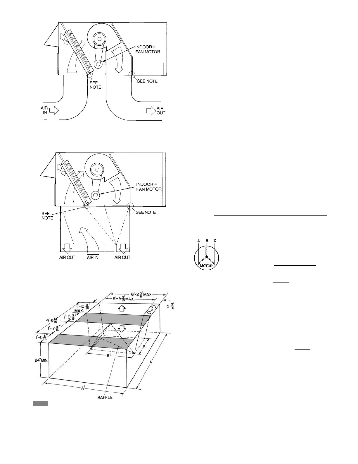
2. The factory asse mbled horizontal adapter substantially improves
fan performance. See Fig. 30.
3. The static pressure must be added to external static pressure. The
sum and the indoor-air section entering-air cfm should then be
used in conjunction with the Fan Performance table to deter mine
blower rpm, bhp, and watts.
Table 13 — Fan Rpm at Motor Pulley Settings* (Factory-Supplied Drives)
UNIT 542J
0
1
/
2
11
1
/
2
150 † † 1132 1105 1078 1051 1024 997 970 943 916 889 862
180 † † 1010 989 968 947 926 905 883 862 841 820 799
*Approximate fan rpm shown.
†Due to belt and pulley size, pulley cannot be set to this number of turns
open.
MOTOR PULLEY TURNS OPEN
22
1
/
2
33
NOTE: To run units at speeds not listed, field-supplied drives are
required.
1
/
2
44
1
/
2
551/
0.12
0.17
0.12
0.17
6
2
Table 14 — Indoor-Fan Motor Performance
UNIT
542J
UNIT
VOLTAGE
ACCEPTABLE
CONTINUOUS
BHP*
MAXIMUM
150
180
208/230
460 4.9 85.8
208/230
460 7.9 87.5
4.25 3775
5.90 5180
LEGEND *Extensive motor and electrical testing on these units ensures that the
Bhp — Brake Horsepower
MAXIMUM
ACCEPTABLE
OPERATING
MAXIMUM
AMP DRAW
MOTOR
EFFICIENCY
WATTS
10.5 85.8
15.8 87.5
full horsepower range of the motors can be utilized with confidence.
Using fan motors up to the horsepower ratings shown in this table will
not result in nuisance tripping or premature motor failure. Unit warranty
will not be affected.
NOTE: The CRRFCURB013A00 horizontal supply and return adapter
accessory improves 542J fan performance by increasing external static
pressure by amount shown above.
Fig. 30 — Horizontal Supply/Return Fan Performance
with CRRFCURB013A00 Horizontal Supply Adapter
Fig. 31 — Fan Performance Using Accessory
Power Exha ust
—21—
Page 22

VII. OUTDOOR FANS AND MOTORS
Fans and motors are factory set. Refer to Outdoor-Fan
Adjustment section on page 24 as required.
VIII. RETURN-AIR FILTERS
Check that correc t filters are instal led in filter tracks. See
Table 1. Do not operate unit without return-air filters.
IX. OUTDOOR-AIR INLET SCREENS
Outdoor-air inlet screens mu st be in place before op erating
unit.
X. OPERA TING SEQUENCE
A. Cooling, Units Without Economizer
When thermostat calls for cooling, terminals G and Y1 are
energized. The indoor-fan contactor (IFC), reversing valve
solenoids (RVS1 and RVS2 [RVS2 on size 180 only]) and
compressor contactor are energized and indoor-fan motor,
compressor, and outdoor fan starts. The outdoor-fan motor
runs continuously while unit is cooling.
B. Heating, Units Without Economizer
Upon a request for heating from the space thermostat, terminal W1 will be ener gized with 24 v. The IFC, outdoor-fan
contactor (OFC), C1, and C2 (size 180 only) will be energized. The indoor fan, outdoor fans, and compressor no. 1,
and compressor no. 2 are energized and RVS1 and RVS2
(size 180 only) are deenergized and switch position.
If the space temperature continues to fall while W1 is
energized, W2 will be energized with 24 v, and the heater
contactor(s) (HC) will b e energized, which will energize the
electric heater(s).
When the space thermo stat is satisfied, W2 will be deenergized first, and the electric heater(s) will be deenergized.
Upon a further rise in space temperature, W1 will be
deenergized.
C. Cooling, Units With EconoMi$erIV
When free cooling is not avail able, the compressors will be
controlled by the zone thermostat. When free cooling is
available, the outdoor-air damper is modulated by the
EconoMi$erIV c on tr o l to p rov id e a 50 to 5 5 F supply-air temperature into the zone. As the supply-air temperature fluctuates above 55 o r below 50 F, the dampers will be modu lated
(open or close) to bring the supply-air temperature back
within set point limits.
For EconoMi$erIV operation, there must be a thermostat
call for the fan (G). This will move the damper to its minimum position during the occupied mode.
Above 50 F supply-air temperature, the dampers will modulate from 100% o pen to the minimum open po sition. From
50 F to 45 F supply-air temperature, the dampers will maintain at the minimum open position. Below 45 F the dampers
will be completely shut. As the supply-air temperature rises,
the dampers will com e ba ck ope n to the m inim u m ope n po si tion once the supply-air temperature rises to 48 F.
If optional power exhaust is installed, as the outdoor-air
damper opens and c loses, the power exhaust fan will be e nergized and deenergized.
If field-installed accessory CO
sensors are connecte d to the
2
EconoMi$erIV control, a demand controlled ventilation
strategy will begin to operate. As the CO
increases abov e the CO
set point, the minimum position of
2
level in the zone
2
the damper will be increased proportionally. As the CO2 level
decreases because of the increase in fresh air, the outdoor-air
damper will be propo rtionally closed. Damper position will
follow the higher demand condition from DCV mode or free
cooling mode.
Damper movement from full closed to full open (or vice
versa) will take between 1
1
/2 and 21/2 minutes.
If free cooling can be used as determined from the appropriate changeover command (switch, dr y bulb, enthalpy curve,
differential dry bulb, or differential enthalpy), a call for cooling (Y1 closes at the thermostat) will cause the control to
modulate the dampers open to maintain the supply a ir temperature set point at 50 to 55 F.
As the supply-air temperature drops below the set point range
of 50 to 55 F, the control will modulate the outdoor-air dampers closed to maintain the proper supply-air temperature.
D. Heating, Units With EconoMi$erIV
When the room thermostat calls for heat, the heating
controls are energized as described in the Heating, Units
Without Economizer section. When the indoor fan is
energized, the economizer damper moves to the minimum
position. When the indoor fan is off, the economizer damper
is fully closed.
E. Defrost
When the tempera ture of the outdoo r coil drops bel ow 28 F
as sensed by the defros t thermostat (DFT2) and the defr ost
timer is at the end of a timed period (adjustable at 30, 50, or
90 minutes), reversing valve solenoids (RVS1 and RVS2) are
energized and the OFC is deenergized. This switches the
position of the reversing valves and shuts off the outdoor fan.
The electric heaters (if installed) will be energized.
The unit continues to defrost until the coil temperature as
measured by DFT2 (see Fi g. 32 ) reach es 65 F, or the duration
of defrost cycle completes a 10-minute period.
During the Defrost mode, if circuit 1 defrosts first, RVS1 will
oscillate between Heating and Cooling modes until the
Defrost mode is complete.
At the end of the defrost cycle, the electric heaters (if
installed) will be deenergized; the reversing valves switch
and the outdoor-fan motor will be energized. The unit will
now operate in the Heating mode.
If the space thermostat is satisfied during a defrost cycle, the
unit will continue in the Defrost mode until the time or temperature constraints are satisfied.
DEFROST
THERMOSTAT
NOTE: Defrost thermostat is located at the bottom tee of circuit no. 1
and the top tee of circuit no. 2.
Fig. 32 — Defrost Thermostat Location
—22—
Page 23

SERVICE
WARNING: Before performing service or mainte-
nance operations on unit, turn off main power switch to
unit. Turn off accessory heater power switch if applicab le.
Electrical shock could cause personal injury.
I. CLEANING
Inspect unit i nterior at beginni ng of each heating and cooling season and as operating conditions require. Remove unit
top panel and/or side panels for access to unit interior.
A. Indoor Coil
Clean as required with a commercial coil cleaner.
B. Outdoor Coil
Clean outdoor coil annually and as required by location and
outdoor-air conditions. Inspect coil monthly — clean as
required.
C. Condensate Drain
Check and clean each year at start of cooling season.
D. Filters
Clean or replace at start of each heating and cooling season,
or more often if operating conditions require. Refer to Table 1
for type and size.
E. Outdoor-Air Inlet Screens
Clean screens with steam or hot water and a mild detergent.
Do not use throwaway filters in place of screens.
II. LUBRICATION
A. Compressors
Each compressor is charged with the correct amount of oil at
the factory. Observe the level in the sight glass immediately
after shutdown while the oil is still warm. If the oil level is
observed when the oil is cold, the level observed may be a
mixture of oil and refrigerant which is not a true indication
of the oil level. If oil level observed is not between the low
limit and high limit levels as indicated in Fig. 33, add oil
until it is in the correct range.
B. Fan Shaft Bearings
For size 150 units, bearings are permanently lubricated. No
field lubrication is required. For size 180 units, the bearings
are of the pillow block type and have grease fittings. The
bearing opposite the motor end has an extended tube line so
it can be lubricated from the motor side. Lubricate the bearings twice annually.
Typical lubricants are given below:
MANUFACTURER LUBRICANT
Texaco Regal AFB-2*
Mobil Mobilplex EP No. 1
Sunoco Prestige 42
Texaco Multifak 2
*Preferred lubricant because it contains rust and oxidation inhibitors.
C. Outdoor and Indoor-Fan Motor Bearings
The outdoor and indoor-fan motors have permanently sealed
bearings, so no field lubrication is necessary.
III. INDOOR FAN, 542J150 UNITS
A. Performance Adjustment
Fan motor pulleys on the 542J150 units are factory set for
speed shown in Table 1.
To change fan speeds :
1. Shut off unit power supply.
2. Loosen belt by loosening fan motor mounting plate
nuts.
3. Loosen movable-pulley flange setscrew (see Fig. 34).
4. Screw movable flange toward fixed flange to increase
speed and away from fixed flange to decrease speed.
Increasing fa n speed i ncreases load on mo tor. Do not
exceed maximum speed specifie d in Table 1.
5. Set movable flange at nearest keyway of pulley hub
and tighten setscrew.
To align fan and motor pulleys:
1. Loosen fan pulley setscrews.
2. Slide fan pulley along fan shaft.
3. Make angular alignment by loosening motor from
mounting plate.
B. Service and Replacement (see Fig. 35)
NOTE: To remove belts only, follow Steps 1-7.
1. Remove filter and supply-air section panels.
2. Remove unit top panel.
3. Remove coil guard.
4. Loosen screws A and B on both sides of motor mount
assembly.
5. Loosen screw C.
6. Rotate motor mount assembly (with motor attached)
as far as possible away from indoor coil.
7. Remove belt.
8. Rotate motor mount assembly back past original
position toward indoor coil.
9. Remove motor mounting nuts D and E (both sides).
10. Lift motor up through top of unit.
11. Reverse Steps 1-10 to install new motor.
12. Check and adjust belt tension as necessary.
Fig. 33 — Compressor Sight Glass Oil Level
Fig. 34 — Indoor-Fan Pulley Alignment and Adjustment
—23—
Page 24

Fig. 35 — 542J150 Indoor-Fan Motor Section
IV. INDOOR FAN, 542J180 UNITS
A. Performance Adjustment
Fan motor pulleys are factory set for speed shown in Table 1.
To change fan speeds :
1. Shut off unit power supply.
2. Loosen nuts on th e 2 carriage bolts in the mo unting
base. Install jacking bolt and plate under motor base
(bolt and plate are shipped in installer’s packet).
Using bolt and plate, raise motor to top of slide and
remove belt. Secure motor in this position by tightening the nuts on the carriage bolts.
3. Loosen movable-pulley flange setscrew (See Fig. 34).
4. Screw movable flange toward fixed flange to increase
speed and away from fixed flange to decrease speed.
Increasing fan speed incr eases lo ad on motor. Do not
exceed maximum speed specified in Table 1. See
Table 9 for air quantity limits.
5. Set movable flange at nearest keyway of pulley hub
and tighten setscrew. (See Table 1 for speed change
for each full turn of pulley flange.)
6. Replace and tighten belts. See Belt Tension Adjustment section below.
To align fan and motor pulleys:
1. Loosen fan pulley setscrews.
2. Slide fan pulley along fan shaft.
3. Make angular alignment by loosening motor from
mounting plate.
B. Service and Replacement (see Fig. 36)
The 542J180 units use a fan motor mounting system that
features a slide-out motor mounting plat e. To replace or service the motor, slide out the bracket.
1. Remove the indoor-fan access panel and the heating
control access panel.
2. Remove the center post (located between the indoor
fan and heating control access panels) and all screws
securing it.
3. Loosen nuts on the two carriage bolts in the motor
mounting base.
4. Using jacking bolt under motor base, raise motor to
top of slide and remove belt. Secure motor in this
position by tightening the nuts on the carriage bolts.
5. Remove the belt drive.
6. Remove jacking bolt and tapped jacking bolt plate.
7. Remove the 2 screws that secure the motor mounting
plate to the motor support channel.
8. Remove the 3 screws from the end of the motor support channel that interfere with the motor slide path.
9. Slide out the motor and motor mounting plate.
10. Disconnect wiring connections and remove the 4
mounting bolts.
11. Remov e the motor.
12. To install the new motor, reverse Steps 1-11.
13. Check and adjust belt tension as necessary.
V. BELT TENSION ADJUSTMENT
To adjust belt tension:
1. Loosen fan motor bolts.
2. a. Size 150 units:
Move motor mounting plate up or down for proper
belt tension (
1
/2 in. deflection w ith one finger).
b. Size 180 units:
Turn motor jacking bolt to move motor mounting
plate up or down for proper belt tension (3/8 in.
deflection at midspan with one finger [9 lb force]).
3. Tighten nuts.
4. Adjust bolts and nut on mounting plate to secure
motor in fixed position.
VI. OUTDOOR-FAN ADJUSTMENT (Fig. 37)
1. Turn off unit power supply.
2. Remove access panel(s) closest to the fan to be
adjusted.
3. Loosen fan hub setscrews.
4. Adjust the fan height on the shaft using a straight-
edge placed across the fan orifice.
5. Tighten setscrews and replace panel(s).
6. Turn on unit power.
VII. POWER FAILURE
Dampers have a spring return. In event of power failure,
dampers will return to fully closed position until power is
restored. Do not manually operate damper motor.
—24—
Page 25

NOTE: A 31/2-in. bolt and threaded plate are included in the installer’s
packet. They can be added to the motor support channel below the
motor mounting plate to aid in raising the motor.
Fig. 36 — 542J180 Indoor-Fan Motor Section
NOTE: Dimensions are in inches.
Fig. 37 — Outdoor Fan Adjustment
VIII. REFRIGERANT CHARGE
Amount of refrigerant charge is listed on unit nameplate and
in Table 1.
Unit panels must be in place when unit is operating during
charging procedure.
A. No Charge
Use standard evacuating techniques. After evacuating system, weigh in the specified amount of re frigerant (refer to
Table 1).
B. Low Charge, Cooling
Using appropriate cooling charging chart (see Fig. 38 and
39), add refrigerant until conditions of the chart are met.
Note that charging charts are different from those normally
used. Charts are based on ch arging units to correct superheat for various operating co nditions. An accurate pressure
gage and temperature sensin g device are required. Connec t
temperature sensing device to service port on suction line
and insulate it so that outdoor ambient temperature does not
affect reading. Indoor-air cfm must be within normal operating range of unit.
C. To Use Cooling Charging Chart
Take outdoor ambient temperature and read the suction
pressure gage. Refer to appropriate chart to determ ine correct suction temperature. If suction temperature is high, add
refrigerant. If suction tem perature is low, careful ly recover
some of the charge. Recheck suction pressure as charge is
adjusted.
Example (Fig. 39)
Outdoor Temperature . . . . . . . . . . . . . . . . . . . . . . . . . . . .8 5 F
Suction Pressure . . . . . . . . . . . . . . . . . . . . . . . . . . . . . .70 psig
Suction Temperature Should be . . . . . . . . . . . . . . . . . . . .60 F
(Suction Temperature may vary ± 5 F.)
D. Low Charge, Heating
If outdoor ambient temperature is above 40 F, operate unit
on cooling and refer to Low Charge, Cooli ng se ction ab ove. If
outdoor ambient is below 40 F, evacuate sys tem and weigh in
specified amount of refrigerant. (Refer to Table 1.)
IX. FILTER DRIER
Replace whenever refrigerant system is exposed to
atmosphere.
X. PROTECTIVE DEVICES
A. Compressor Protection
Overcurrent
Each compressor has one manu al reset, calibrated trip, mag-
netic circuit bre aker. Do not bypass c onnections or incr ease
the size of the circuit break er to correct trouble. Determine
the cause of the trouble and c orrect it before resetting the
breaker.
Overtemperature
Each compressor has internal protector to protect it against
excessively high discharge gas temperature.
Crankcase Heater
Each compres sor ha s 125-wa tt cran kcase heat ers to preven t
absorption of liq uid r efri ge rant by oi l in the cr ank case when
the compressor is idle. Since power for the crankcase heaters
is drawn from the unit incoming power, main unit power
must be on for the heaters to be energized.
IMPORTANT: After a prolonged shutdown or service job,
energize the crankcase heaters for 24 hours before starting
the compressors.
Compressor Lockout
If any of the saf eties (high-pressure or low-pressure, freeze
protection thermostat, compressor internal thermostat) trip,
or if there is loss of power to the compressor s, the CLO (compressor lockout) will lock the compressor s off. To reset, manually move the thermostat setting.
B. Indoor-Fan Motor Protection
A manual reset, calibrated trip, magnetic circuit breaker
protects against ov ercurrent. Do not bypass connections or
increase the size of the breaker to correct trouble. Determine
the cause and correct it before r esetting the breaker.
C. Outdoor-Fan Motor Protection
Each outdoor-fan motor is internally protected against
overtemperature.
—25—
Page 26

Fig. 38 — Cooling Charging Chart, 542J150 Units
D. High and Low-Pressure Switches
If either switch trips, or if the compressor overtemperature
switch activates, that refrigerant circuit will be automatically locked out by the CLO. To reset, manually move the
thermostat setting.
E. Freeze Protection Thermostat (FPT)
An FPT is located on the indoor coil. It detects frost build-up
and turns off the compressor, allowing the coil to clear. Once
the frost has melted, the compressor can be reenergized by
resetting the CLO from the thermostat.
XI. RELIEF DEVICES
All units have relief devices to protect against damage from
excessive pressu res (i.e., fire). These devices protect the high
and low side.
XII. CONTROL CIRCUIT, 24-V
This control circuit is protected against overcurrent by a
3.2-amp circuit breaker. Breaker can be reset. If it trips,
determine cause of trouble before resetting. Typical wiring is
shown in Fi g. 40 and 41.
XIII. OPTIONAL HINGED ACCESS DOORS
When the option al se rvic e pac ka ge is ord ered or i f the hin ged
access doors option is ordered, the unit will be provided
with external and internal hi nged access doors to facilitate
service.
Four external hinged access doors are provided. All external
doors are provid ed with 2 l arge
1
/4 turn latches with folding
bail-type handles. (Compressor access doors have one latch.)
A single door is provided for filter and drive access. One door
is provided for control box access. The control box access door
is interlocked with the non-fused disconnect which must be
in the OFF position to open the door. Two doors are provided
for access to the compressor compartment.
Two internal access doors are provided inside the filter/drive
access door. The filter access d oo r (on t he left) is secured by 2
1
small
/4 turn latches with folding bail-type handles. This
door must be opened prior to opening the drive access door.
The drive access door is shipped with 2 sheet metal screws
holding the door closed. Upon initial opening of the door,
these screws may be removed and discarded. The door is
then held shut by the filter access door, which closes over it.
XIV. REPLACEMENT PARTS
A complete list of repl acement parts may be obtained from
any Bryant distributor upon request.
Fig. 39 — Cooling Charging Chart, 542J180 Units
—26—
Page 27

Fig. 40 — Typical Wiring Diagram (542J150, 208/230-3-60 V Shown)
—27—
Page 28

Fig. 41 — Typical Component Arrangement (542J150, 208/230-3-60 V Shown)
—28—
Page 29

LEGEND AND NOTES FOR FIG. 40 AND 41
LEGEND
AHA — Adjustable, Heat Anticipator
BRK W/AT — Breaks with Amp Turns
C—Contactor, Compressor
CAP — Capacitor
CB — Circuit Breaker
CC — Cooling Compensator
CH — Crankcase Heater
CLO — Compressor Lockout
COMP — Compressor Motor
CTD — Compressor Time Delay
DB — Defrost Board
DFT — Defrost Thermostat
DM — Damper Motor
DR — Defrost Relay
DU — Dummy Terminal
EQUIP — Equipment
FL — Fuse Link
FPT — Freeze Protection Thermostat
FU — Fuse
GND — Ground
HC — Heater Contactor
HPS — High-Pressure Switch
HR — Heat Relay
HTR — Heater
IAQ — Indoor Air Quality Sensor
IFC — Indoor-Fan Contactor
IFCB — Indoor-Fan Circuit Breaker
IFM — Indoor-Fan Motor
IP — Internal Protector
L—Light
LALS — Low Temperature Compressor
LPS — Low-Pressure Switch
LS — Limit Switch
NEC — National Electric Code
OAT — Outdoor Air Temperature Sensor
OCCUP — Occupancy Sensor
Lockout Switch
OFC — Outdoor Fan Contactor
OFM — Outdoor Fan Motor
OP — Overcurrent Protector
PL — Plug Assembly
QT — Quadruple Terminal
RVR — Reversing Valve Relay
RVS — Rev ersing Valve Solenoid
TB — Terminal Block
TC — Ther m osta t Cooling
TH — Ther m osta t Heating
TRAN — Transformer
Terminal (Marked)
Terminal (Unmarked)
Terminal Block
Splice
Factory Wiring
Field Wiring
Option/Accessory Wiring
To indicate common potential only;
not to represent wiring.
Economizer Motor
Remote POT Field Accessory
OAT Sensor
Disch Air Sensor
RAT Accessory Sensor
Low Ambient Lockout Switch
NOTES:
1. Compressor and/or fan motor(s) thermally protected three-phase motors protected against primar y single
phasing conditions.
2. If any of the original wire furnished must be replaced, it must be replaced with T y pe 90° C or its equiv alent.
3. TRAN1 is wired for 230-v operation. If unit is 208-v, disconnect the black wires from the ORN TRAN wire
and reconnect to the RED TRAN wire, apply wirenuts to wires.
4. CB1,2 must trip amps are equal to or less than 156% FLA, IFCB 140%.
5. The CLO locks out the com pressor to p revent short cycling on com pressor overload and safety devices;
before replacing CLO, check these devices.
6. Jumpers are omitted when unit is equipped with economizer.
7. Number(s) indicates the line location of used contacts. A bracket over (2) numbers signifies a single pole,
double throw contact. An underlined number signifies a norm ally closed contact. Plain (no line) number
signifies a normally open contact.
8. Remove jumper between RC & RN.
9. 620 Ohm, 1 watt, 5% resistor should be removed only when using differential enthalpy or dry bulb.
10. If a separate field-supplied 24-v transformer is used for the IAQ sensor power supply, it cannot have the
secondary of the transformer grounded.
11. OAT sensor is shipped inside unit and must be relocated in the field for proper operation.
12. For field-installed remote minimum position POT, remove black wire jumper between P and P1 and set
control minimum position POT to the minimum position.
—29—
Page 30

TROUBLESHOOTING
I. UNIT TROUBLESHOOTING
Refer to Table 15 and Fig. 42-45, for assistance when troubleshooting the 542J units.
A. Cooling Cycle
1. Hot gas from compressor flows through the 4-way
valve and is directed to the outdoor-coil header. At
the header it is condensed and subcooled through
converging circuits (7-2-1). Refrigerant leaves the
outdoor-coil by way of the check valve to the liquid
line.
2. The refrigerant then flows through the filter drier
and feeds the indoor coil by way of fixed orifice tubes
on each circuit.
3. Each circuit evaporates the refrigerant, and the circuits are combined in the indoor-coil header with
some of the circuits flowin g through the check valve.
4. The refrigerant then flows through the 4-way valve,
accumulator and back to the compressor.
B. Heating Cycle
1. Hot gas from the compressor flows through the 4-way
valve and is directed to the indoor-coil header. At the
header it is condensed and directed through subcooling circuits and out the indoor-coil check valve to the
liquid line.
2. The refrigerant then flows through a strainer and
feeds the outdoor-coil by way of fixed orific e tubes on
each circuit.
3. Each circuit evaporates the refrigerant, and the circuits are combined in the outdoor-coil header with
some of the circuits flowin g through the check valve.
4. The refrigerant then flows through the 4-way valve,
accumulator and back to the compressor.
II. ECONOMI$ERIV TROUBLSHOOTING
See Table 16 for EconoMi$erIV logic.
A functional view of the Econ oMi$erIV is shown in Fig. 46.
Typical settings, sensor ranges, and jumper positions are
also shown. An EconoMi$erIV simulator program is available from Bryant to help with EconoMi$erIV training and
troubleshooting.
A. EconoMi$erIV Preparation
This procedure is used to prepare the EconoMi$erIV for
troubleshooting. No troubleshooting or testing is done by
performing the following procedure.
NOTE: This procedure requires a 9-v battery, 1.2 kilo-ohm
resistor, and a 5.6 kilo-ohm resistor which are not supplied
with the EconoM i$ er IV.
IMPORTANT: Be sure to record the positions of all potentiometers before star ting troubleshooting.
1. Disconnect power at TR and TR1. All LEDs should be
off. Exhaust fan contac ts should be open.
2. Disconnect device at P and P1.
3. Jumper P to P1.
4. Disconnect wires at T and T1. Place 5.6 kilo-ohm
resistor across T and T1.
5. Jumper TR to 1.
6. Jumper TR to N.
7. If connected, remove sensor from terminals S
and +.
O
Connect 1.2 kilo-ohm 4074EJM checkout resistor
across terminals S
8. Put 620-ohm resistor across terminals S
and +.
O
and +.
R
9. Set minimum position, DCV set point, and exhaust
potentiometers fully CCW (counterclockwise).
10. Set DCV maximum position potentiometer fully CW
(clockwise).
11. Set enthalpy potentiometer to D.
12. Apply power (24 vac) to terminals TR and TR1.
B. Differential Enthalpy
To check differential enthalpy:
1. Make sure EconoMi $erIV preparat ion procedure h as
been performed.
2. Place 620-ohm resistor across S
3. Place 1.2 kilo-ohm resistor across S
and +.
O
and +. The Free
R
Cool LED should be lit.
4. Remove 620-ohm resistor across S
and +. The Free
O
Cool LED should tu rn off.
5. Return EconoMi$erIV settings and wiring to normal
after completing troubleshooting.
C. Single Enthlapy
To check si ngle enthalpy:
1. Make sure EconoMi $erIV preparat ion procedure h as
been performed.
2. Set the enthalpy potentiometer to A (fully CCW). The
Free Cool LED should be lit.
3. Set the enthalpy potentiometer to D (fully CW). The
Free Cool LED should turn off.
4. Return EconoMi$erIV settings and wiring to normal
after completing troubleshooting.
D. DCV (Demand Controlled Ventilation) and Power
Exhaust
To check DCV and Power Exhaust:
1. Make sure EconoMi $erIV preparat ion procedure h as
been performed.
2. Ensure terminals AQ and AQ1 are open. The LE D for
both DCV and Exhaust should be off. The actuator
should be fully closed.
3. Connect a 9-v battery to AQ (positive node) and AQ1
(negative node). The LED for both DCV and Exhaust
should turn on. The a ctua tor s hou ld dri ve to be tween
90 and 95% open.
4. Turn the Exhaust potentiometer CW until the
Exhaust LED turns off. The LED should turn off
when the potentiometer is approximately 90%. The
actuator should remain in position.
5. Turn the DCV set point potentiometer CW until the
DCV LED turns off. The DCV LED should turn off
when the potentiometer is approximately 9 v. The
actuator should drive fully closed.
6. Turn the DCV and Exhaust potentiometers CCW
until the Exhaust LED turns on. The exhaust contacts will close 30 to 120 seconds afte r the Exhaust
LED turns on.
7. Return EconoMi$erIV settings and wiring to normal
after completing troubleshooting.
—30—
Page 31

E. DCV Minimum and Maximum Position
To check the DCV minimum and maximum position:
1. Make sure EconoM i$erIV prepara tion procedu re has
been performed.
2. Connect a 9-v battery to AQ (positive node) and AQ1
(negative node). Th e DCV LED should turn on. The
actuator should drive to between 90 and 95% open.
3. Turn the DCV Maximum Position potentiometer to
midpoint. The actuator should drive to between 20
and 80% open.
4. Turn the DCV Maximum Position potentiometer to
fully CCW. The actuator should drive fully closed.
5. Turn the Minimum Position potentiometer to midpoint. The actu ator should drive to bet ween 20 and
80% open.
6. Turn the Minimum Position Potentiometer fully CW.
The actuator should drive fully open.
7. Remove the jumper from TR and N. The actuator
should drive fully closed.
8. Return EconoMi$erIV settings and wiring to normal
after completing troubleshooting.
F. Supply-Air Input
To check supply-air input:
1. Make sure EconoM i$erIV prepara tion procedu re has
been performed.
2. Set the Enthalpy potentiometer to A. The Free Cool
LED turns on. The actuator should drive to between
20 and 80% open.
3. Remove the 5.6 kilo-ohm resistor and jumper T to T1.
The actuator should drive fully open.
4. Remove the jumper across T and T1. The actuator
should drive fully closed.
5. Return EconoMi$erIV settings and wiring to normal
after completing troubleshooting.
G. EconoMi$erIV Troubleshooting Completion
This procedure is used to return the Eco no Mi$ er IV to op eration. No trouble shooting or testing is done by performing the
following procedure.
1. Disconnect power at TR and TR1.
2. Set enthalpy potentiometer to previous setting.
3. Set DCV maximum position potentiomete r to previous setting.
4. Set minimum position, DCV set point, and exhaust
potentiometers to previous settings.
5. Remove 620-ohm resistor from terminals S
and +.
R
6. Remove 1.2 kilo-ohm checkout resistor from terminals
S
and +. If used, reconnect sensor from terminals S
O
and +.
7. Remove jumper from TR to N.
8. Remove jumper from TR to 1.
9. Remove 5.6 kilo-ohm resistor from T and T1. Reconnect wires at T and T1.
10. Remov e jumper from P to P1. Reconn ect device at P
and P1.
11. Apply power (24 vac) to terminals TR and TR1.
O
CHECK VALVE
IDENTIFICATION
(See Fig. 42 and 43)
A
B
C
D
E
F
LOCATION
Outdoor coil;
Header
Outdoor coil;
Liquid line feeding
fixed orifice
Outdoor coil;
Liquid line leaving
coil
Indoor coil; Liquid
line feeding fixed
orifice
Indoor coil; Liquid
line leaving coil
Indoor coil;
Header
Table 15 — Check Valve Functions
COOLING
CYCLE
Closed Open
Open Closed Normal
Closed Open
Open Closed Normal
Closed Open
Open Closed Normal
HEATING
CYCLE
Lose circuiting in
outdoor coil. Acts
like low charge.
Restricted
liquid line
Bypasses coil and
floods compressor
COOLING CYCLE
CHECK VALVE STUCK
Open Closed Open Closed
Normal Normal
Lose some
capacity
Normal Normal
Restricted
indoor
fixed orifice
Normal Normal
Bottom circuits
of indoor coil
inactive
Restricted outdoor
fixed orifice
Lose some capacity Normal
Lose indoor coil
circuiting — symptom
of low charge
HEATING CYCLE
CHECK VALVE STUCK
Bottom 3 circuits
restricted
Normal
Flooding outdoor
coil and compressor
Restricted
liquid line
Normal
—31—
Page 32

LEGEND
→ — Refrigerant Flow Direction
∆ — Check Valve Flow Direction
X—Fixed Orifice
NOTE: Circuitry shown is for single system; 542J180 units have
2 individual and independent refrigeration systems that each
operate in an identical manner.
Fig. 42 — Heat Pump Cooling Cycle
CHECK VALVE* COOLING
A
B
C
D
E
F
*See Table 15 for check valve operation
details.
Closed
Open
Closed
Open
Closed
Open
LEGEND
→ — Refrigerant Flow Direction
∆ — Check Valve Flow Direction
X—Fixed Orifice
NOTE: Circuitr y shown is for single system; 542J180 units have
2 individual and independent refrigeration systems that each
operate in an identical manner.
Fig. 43 — Heat Pump Heating Cycle
—32—
CHECK VALVE* COOLING
A
B
C
D
E
F
*See Table 15 for check valve operation
details.
Open
Closed
Open
Closed
Open
Closed
Page 33

—33—
Fig. 44 — Troubleshooting Chart, Heating Cycle
ODT — Outdoor Temperature
Page 34

—34—
Fig. 45 — Troubleshooting Chart, Cooling Cycle
Page 35

Table 16 — EconoMi$erIV Input/Output Logic
INPUTS OUTPUTS
Demand Control
Ventil ation (DCV)
Below set
(DCV LED Off)
Above set
(DCV LED On)
*For single enthalpy control, the module compares outdoor enthalpy
to the ABCD set point.
†Power at N terminal determines Occupied/Unoccupied setting:
24 vac (Occupied), no power (Unoccupied).
**Modulation is based on the supply air sensor signal.
††Modulation is based on the DCV signal.
High
(Free Cooling LED Off)
Low
(Free Cooling LED On)
High
(Free Cooling LED Off)
Low
(Free Cooling LED On)
Enthalpy*
Outdoor Return
Low On On On On Minimum position Closed
High On On On Off Modulating** (between min.
Low On On On On M odulating†† (between min.
High On On On Off Modulating*** Modulating†††
Y1 Y2
On Off On Off
Off Off Off Off
On Off Off Off
Off Off Off Off Minimum position Closed
On Off On Off
Off Off Off Off
On Off Off Off
Off Off Off Off
Compressor N Terminal†
Stage1Stage
2
position and full-open)
position and DCV maximum)
***Modulation is based on the greater of DCV and supply air sensor
signals, between minimum position and either maximum position
(DCV) or fully open (supply air signal).
†††Modulation is based on the greater of DCV and supply air sensor
signals, between closed and either maximum position (DCV) or fully
open (supply air signal).
Occupied Unoccupied
Damper
Modulating** (between
closed and full-open)
Modulating†† (between
closed and DCV
maximum)
Fig. 46 — EconoMi$erIV Functional View
—35—
Page 36

Air quantity limits
18
Changeover set points 14
Charging chart, refr igera nt 26
Clearance 5, 6
CO2 sensor
Configuration 17
Settings 15, 17
Compressor
Lockout 13, 25
Lubrication 23
Mounting 18
Concentric duct 7
Condensate drain
Cleaning 23
Location 3, 8
Control circuit
Wiring 8, 9
Convenience outlet 8
Crankcase heater 18, 25
Defrost thermostat 22
Demand control ventilation 16, 17
Dimensions 2, 3, 5, 6
Ductwork 1, 3, 7
EconoMi$erIV 11-17
Control mode 13
Controller wiring 12
Damper movement 16
Demand ventilation control 16
Dry bulb changeover 13
Troubleshooting 30, 31, 35
Usage 13
Wiring 12
Electrical connections 7
Electrical data 9
Enthalpy changeover set points 15
Filter
Cleaning 23
Size 4
Filter drier 25
Freeze protection thermostat 26
Heat anticipator settings 9
High-pressure switch 4
Hinged access doors 26
Horizontal adapter roof curb 3, 21
Indoor air quality sensor 14
Indoor coil 4
Cleaning 23
Indoor fan motor
Lubrication 23
Motor data 21
Performance 19, 20
Pulley adjustment 23
Pulley setting 4, 21
Speed 4
Low-pressure switch 4
Manual outdoor air damper 10
Motormaster I cont ro l 11
Mounting
Compressor 18
Unit 1
Non-fused disconnect 8, 9
Operating limits 18
Operating sequence 22
Cooling 22
Defrost 22
EconoMi$erIV 22
Heating 22
Outdoor air hood 10
Outdoor air i nlet s cre ens
Cleaning 23
Outdoor air temperature sensor 13
Outdoor coil 4
Cleaning 23
Outdoor fan 4
Adjustment 24, 25
Physical data 4
Power exhaust 21
INDEX
Power supply 7
Wiring 8
Pressure, drop
Economizer 21
Electric heat 21
Glycol heat 21
Pressure switches
High pressure 4
Low pressure 4
Refrigerant
Charge 25
Type 4
Refrigerant service ports 18
Replacement parts 26
Return air filter 4, 22
Return air temperature sen sor 14
Rigging unit 1, 3
Roof curb
Assembly 1
Dimensions 2, 3
Leveling tolerances 2
W eight 4
Safety considerations 1
Service 23-29
Start-up 18-22
Start-up checklist CL-1
Supply-air temperature sensor 13
Thermostat 9, 16
Troubleshooting 30-35
W eight
Economizer 4-6
Maximum 3
Unit 4-6
Wind baffle 11
Wiring
EconoMi$erIV 12
Power connections 8
Thermostat 9
Unit 27, 28
—36—
Page 37

SERVICE TRAINING
Packaged Service Training programs are an excellent way to increase your knowledge of the equipment
discussed in this manual, including:
• Unit Familiari zat ion • Maintenance
• Installation Overview • Operating Sequence
A large selection of product, theory, and skills programs are available, using popular video-based formats
and materials. All include video and/or slides, plus companion book.
Classroom Service Training which includes “hands-on” experience with the products in our labs can
mean increased confidence that really pays dividends in faster troubleshooting and fewer callbacks. Course
descriptions and schedules are in our catalog.
CALL FOR FREE CATALOG 1-800-644-5544
[ ] Packaged Service Training [ ] Classroom Service Training
—37—
Page 38

Copyright 2006 Bryant Heating & Cooling Systems Printed in U.S.A. CATALOG NO. 5354-203
Page 39

Page 40

START-UP CHECKLIST
(Remove and Store in Job File)
MODEL NO.: __________________________________ SERIAL NO.: _____________________________________
DATE: ________________________________________ TECHNICIAN: ____________________________________
I. PRE-START-UP
VERIFY THA T ALL PACKING MATERIALS HAVE BEEN REMOVED FROM UNIT
VERIFY PROPER ADJUSTMENT OF INDOOR FAN MOTOR ADJUSTMENT BOLT (150 UNITS) AND
ADJUSTMENT BOL T AND PLATE (180 UNITS)
LOOSEN ALL SHIPPING HOLDDOWN BOLTS PER INSTRUCTIONS
OPEN ALL SERVICE VAL VES (SUCTION, DISCHARGE, AND LIQUID)
VERIFY INSTALLATION OF OUTDOOR-AIR HOOD
VERIFY THA T CONDENSATE CONNECTION IS INSTALLED PER INSTRUCTIONS
VERIFY THA T ALL ELECTRICAL CONNECTIONS AND TERMINALS ARE TIGHT
CHECK THAT AIR INLET FIL TERS ARE CLEAN AND IN PLACE
VERIFY THA T UNIT IS LEVEL
CHECK FAN WHEEL AND PROPELLER FOR LOCATION IN HOUSING/ORIFICE, AND VERIFY SET SCREW
IS TIGHT
VERIFY THA T FAN SHEAVES ARE ALIGNED AND BEL TS ARE PROPERLY TENSIONED
VERIFY THA T CRANKCASE HEATERS HAVE BEEN ENERGIZED FOR AL LEAST 24 HOURS
II. START-UP
ELECTRICAL
CUT ALONG DOTTED LINE
SUPPLY VOL TAGE L1-L2 L2-L3 L3-L1
COMPRESSOR AMPS — COMPRESSOR NO. 1 L1 L2 L3
INDOOR-F AN AMPS — COMPRESSOR NO. 2 (180 ONL Y ) L1 L2 L3
SUPPL Y FAN AMPS EXHAUST FAN AMPS
ELECTRIC HEAT AMPS L1 L2 L3
TEMPERATURES
OUTDOOR-AIR TEMPERATURE F DB (Dry-Bulb)
RETURN-AIR TEMPERATURE F DB F WB (Wet-Bulb)
COOLING SUPPLY AIR F
HEAT PUMP SUPPLY AIR F
ELECTRIC HEAT SUPPL Y AIR F
PRESSURES (COOLING MODE)
REFRIGERANT SUCTION CIRCUIT NO. 1 PSIG CIRCUIT NO. 2 (180 ONL Y) PSIG
REFRIGERANT DISCHARGE CIRCUIT NO. 1 PSIG CIRCUIT NO. 2 (180 ONLY ) PSIG
VERIFY REFRIGERANT CHARGE USING CHARGING CHARTS ON PAGE 26
GENERAL
ECONOMI$ERIV MINIMUM VENT AND CHANGEOVER SETTINGS TO JOB REQUIREMENTS
CUT ALONG DOTTED LINE
Copyright 2006 Bryant Heating & Cooling Systems Printed in U.S.A. CL-1 CATALOG NO. 5354-203
 Loading...