

Page 1
524J
PACKAGED AIR--HANDLING UNITS, 60 Hz
WITH PURONR(R--410A) REFRIGERANT
SIZES: 16, 25, 28, 30
Electrical Data Supplement
NOTE: Read the entire instruction manual before starting the installation
th
This supplement only applies to 524J size 16, 25, 28 & 30 units when the 13
is either a 1, 2, or 3 as shown in the Model Number Nomenclature diagram below. Check the Unit
Nameplate (see Figs. 1 & 2). If the digit in the 13
th
position is not either a 1, 2, or 3 discard this document.
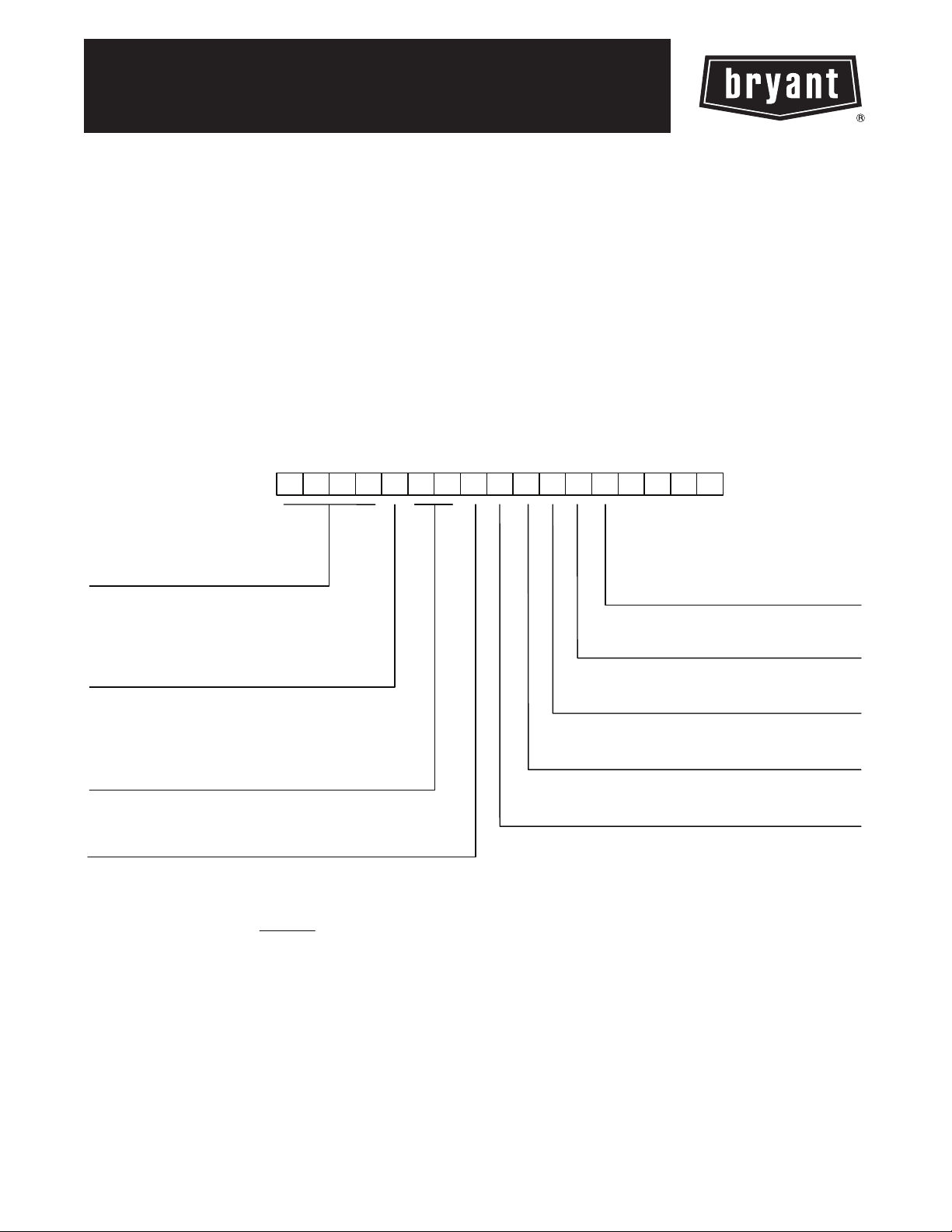
MODEL NUMBER NOMENCLATURE
digit of the Model Number
123456789
524JE16A000A10AAA
Model
524J = Packaged Air-Handling Unit
Puron
Voltage
T = 575-3-60l
J = 208/230-1-60
P = 208/230-3-60
E = 208/230/460-3-60*
Cooling Tons
16 = 15 ton
25 = 20 ton
28 = 25 ton
30 = 30 ton
Type of Coil
A = Standard 4 Row DX Puron Coil
H = Heat Pump
* Size 16 units are triple voltage in the “E” configuration unless
the unit is equipped with the discrete 460-3-60 High Static motor option.
** Size 30 units - designate standard motor and high static drive.
®
R-410A Refirgerant
10 11 12
Factory Assigned
0 = Default
Factory Assigned
0 = Default
13
14 15 16 17
Indoor Fan Options – Belt Drive
1 = Standard Motor/ Standard Drive
2 = Standard Motor / Medimum Drive
3 = High Motor / High Drive**
Coil Options
A = Standard Aluminum Fin / Copper Tube
Factory Assigned
0 = Default
C11002
Page 2
SAFETY CONSIDERATIONS
Improper installation, adjustment, alteration, service,
maintenance, or use can cause explosion, fire, electrical
shock or other conditions which may cause personal
injury or property damage. Consult a qualified installer,
service agency, or your distributor or branch for
information or assistance. The qualified installer or
agency must use factory--authorized kits or accessories
when modifying this product. Refer to the individual
instructions packaged with the kits or accessories when
installing.
Follow all safety codes. Wear safety glasses and work
gloves. Use quenching cloths for brazing operations and
have a fire extinguisher available. Read these instructions
thoroughly and follow all warnings or cautions attached to
the unit. Consult local building codes and appropriate
national electrical codes (in USA, ANSI/NFPA70,
524J
National Electrical Code (NEC); in Canada, CSA C22.1)
for special requirements.
It is important to recognize safety information. This is the
safety--alert symbol
unit and in instructions or manuals, be alert to the
potential for personal injury.
. When you see this symbol on the
!
WARNING
ELECTRICAL SHOCK HAZARD
Failure to follow this warning could cause personal
injury or death.
Before performing service or maintenance operations
on unit, always turn off main power switch to unit and
install lockout tag. Unit may have more than one
power switch.
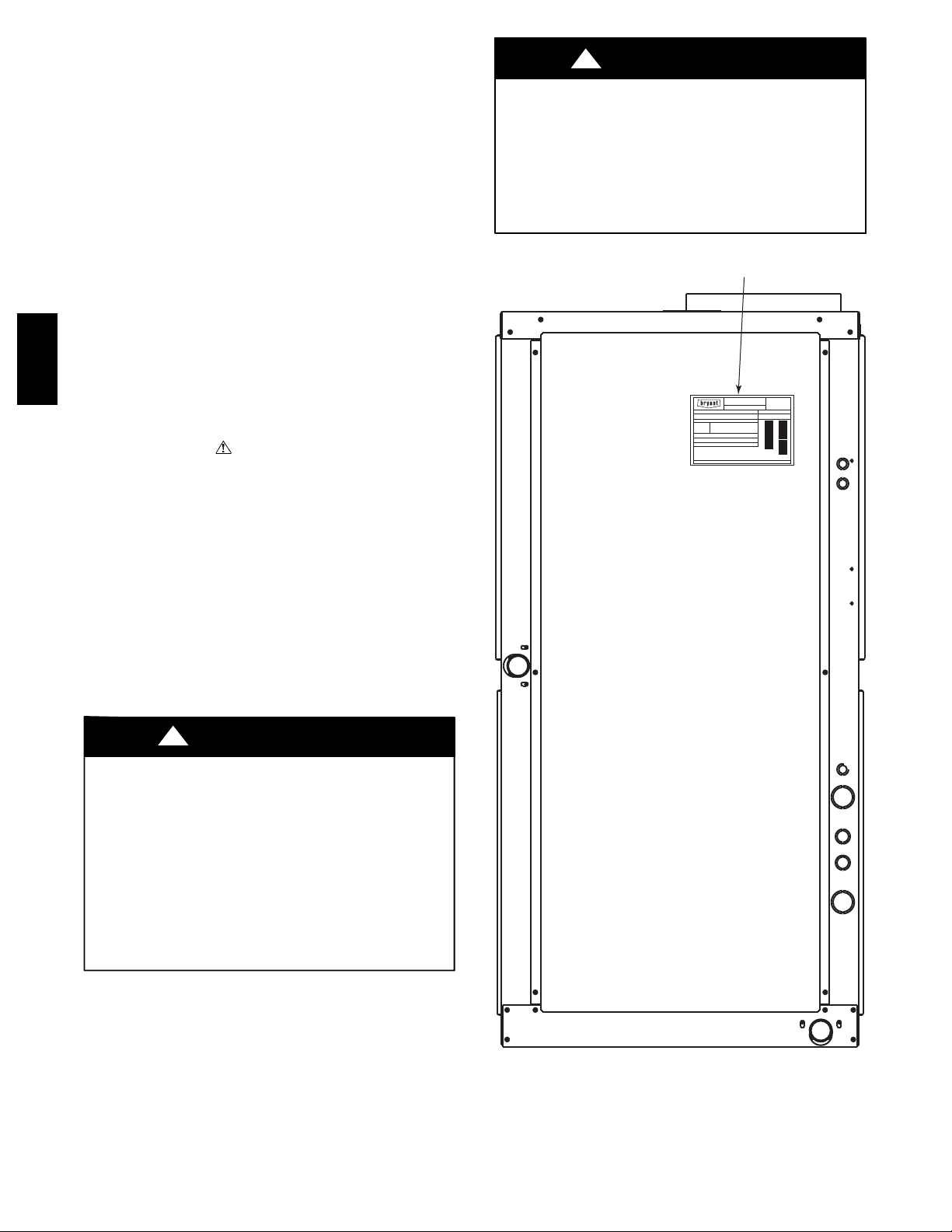
Nameplate Location
MODEL
BRYANT
SERIAL
Compressors (Factory Charged) Refrigerant/System
Qty Volts AC PH Hz RLA LRA lbs kg R
1
2
Fan Motors Qty PHHz FLA HP KWVolts AC
Power
Supply
*MCA (Fuse or HACR Bkr.)
=
Min Circuit Amps
=
Max Over Current Protective Device Amps
*MOCP
Test with External Static
in H20
kPa NOT Suitable for Outdoor Use
Charge System per Installation Instructions
Test Pressure Gage
—
Hi PSI ( kPa)
SERIAL
MODEL
Max
Min
Volts
VoltsPH MCA * MOCP *HzVolts AC
Part Number/Rev
Designed in U.S.A.
Assembled in Mexico
99NA504634/2.0
Understand the signal words DANGER, WARNING,
CAUTION, and NOTE. These words are used with the
safety--alert symbol. DANGER identifies the most serious
hazards which will result in severe personal injury or
death. WARNING signifies hazards which could result in
personal injury or death. CAUTION is used to identify
unsafe practices, which may result in minor personal
injury or product and property damage. NOTE is used to
highlight suggestions which will result in enhanced
installation, reliability, or operation.
!
CAUTION
ELECTRICAL HAZARD
Failure to follow this caution may result in personal
injury or product and property damage.
The electrical data contained in this document is only
for use with 524J size 16, 25, 28 and 30 units which
display either a 1, 2, or 3 in the 13
th
position of the 17
digit model number as displayed on the unit’s
nameplate.
See Fig. 1 for location of the unit’s nameplate.
See Fig. 2 for details of the 17 digit model number.
C11003
Fig. 1 -- Location of Unit Nameplate
2
Page 3

MODEL
524JE16A000A10AAA
SERIAL
Compressors (Factory Charged) Re fri ger ant /Syst em
Qty Volts AC PH Hz RLA LRA lbs kg R
1
2
Fan Motors Qty PH Hz FLA HP KWVolts AC
BRYANT
—
Test Pressure Gage
Hi PSI ( kPa)
MODEL
SERIAL
Power
Supply
* MCA (Fuse or HACR Bkr.)
=
Min Circuit Amps
=
*MOCP
Test with External Static
Charge System per Installation Instructions
Max Over Current Protective Device Amps
in H20
kPa NOT Suitable for Outdoor Use
512
Max
Volts
43J4E51
2
Min
VoltsPH MCA * MOCP *HzVolts AC
Model Number
67A80
6
Position of Digit
Fig. 2 -- Example of Nameplate with Model Number
Table 1 – Electrical Data, Standard Motors
Designed in U.S.A.
Assembled in Mexico
09011A12113014A15A16A
10
17
524J
Part Number/Rev
99NA504644/2.0
C11004
UNIT V --- P H --- H z
524J*16A
524J
*16H
524J*25A
524J*25H
524J*28A
524J*30A
208/230--- 3 ---60 187--- 253 3.7 (2.76) 10.6 13.3 20
4 6 0 --- 3 --- 6 0 414--- 506 3.7 (2.76) 4.6 6.0 15
5 7 5 --- 3 --- 6 0 518--- 632 3.0 (2.24) 3.8 4.8 15
208/230--- 3 ---60 187 --- 253 5.0 (3.73) 14.6/12.8 18.3/16.0 30/25
4 6 0 --- 3 --- 6 0 414 --- 506 5.0 (3.73) 6.4 8.0 15
5 7 5 --- 3 --- 6 0 518 --- 632 5.0 (3.73) 5.1 6.4 15
208/230--- 3 ---60 187 --- 253 7.5 (5.59) 21.4/19.4 26.9/24.3 45/40
4 6 0 --- 3 --- 6 0 414 --- 506 7.5 (5.59) 9.7 12.1 20
5 7 5 --- 3 --- 6 0 518 --- 632 7.5 (5.59) 7.8 9.8 15
208/230--- 3 ---60 187 --- 253 10.0 (7.46) 28.2/26.8 35.3/33.5 60/60
4 6 0 --- 3 --- 6 0 414 --- 506 10.0 (7.46) 13.4 16.8 30
5 7 5 --- 3 --- 6 0 518 --- 632 10.0 (7.46) 10.3 12.9 20
{
VOLTAGE
NOTE: See page 5 for table legend and notes
LIMITS
FAN MOTOR POWER SUPPLY
Hp (kW) FLA
3
Minimum
Circuit Amps
MOCP
Page 4

Table 2 – Electrical Data, Alternate Motors
UNIT V --- P H --- H z
208/230--- 3 ---60 187 --- 253 5.0 (3.73) 14.6/12.8 18.3/16.0 30/25
524J*16A
524J
*16H
4 6 0 --- 3 --- 6 0 414 --- 506 5.0 (3.73) 6.4 8.0 15
5 7 5 --- 3 --- 6 0 518 --- 632 5.0 (3.73) 5.1 6.4 15
208/230--- 3 ---60 187 --- 253 7.5 (5.59) 21.4/19.4 26.9/24.3 45/40
524J*25A
524J*25H
4 6 0 --- 3 --- 6 0 414 --- 506 7.5 (5.59) 9.7 12.1 20
5 7 5 --- 3 --- 6 0 518 --- 632 7.5 (5.59) 7.8 9.8 15
208/230--- 3 ---60 187 --- 253 10.0 (7.46) 28.2/26.8 35.3/33.5 60/60
524J*28A
524J*30A
4 6 0 --- 3 --- 6 0 414 --- 506 10.0 (7.46) 13.4 16.8 30
5 7 5 --- 3 --- 6 0 518 --- 632 10.0 (7.46) 10.3 12.9 20
NOTE: See below for table legend and notes
524J
Legend and Notes for Tables 1 and 2
LEGEND:
F L A --- F u l l L o a d A m p s
MOCP --- Maximum Overcurrent P rotection
{
Motors are designed for satisfactory operation within 10% of
normal voltage shown. Voltages should not exceed the limits
shown in the Voltage Limits column.
NOTES:
1. Minimum circuit amps (MCA) and MOCP values are calcu-
lated in accordance with The NEC. Article 440.
2. Motor FLA values are established in accordance with Under-
writers’ Laboratories (UL). Standard 1995.
3. Unbalanced 3-Phase Supply Voltage
Never operate a motor where a phase imbalance in supply
voltage is g reater than 2%. Use the formula in the example
(see column to the right) to determine the percentage of voltage imbalance.
4. Installation with Accessory Electric Heaters
Size the Field Power Wiring between the heater TB1 and the
40RU indoor fan motor per NEC Article 430--- 28 (1) or (2)
(depends on length of conduit between heater enclosure and
40RU power entry location). Install wires in field ---installed
conduit.
{
VOLTAGE
LIMITS
FAN MOTOR POWER SUPPLY
Hp (kW) FLA
Minimum
Circuit Amps
MOCP
Example: Supply voltage is 230-3-60
% Voltage Imbalance = 100 x
max voltage deviation from average voltage
average voltage
AB = 393 v
BC = 403 v
AC = 396 v
Average Voltage =
(393 + 403 + 396)
3
= 397
1192
=
3
Determine maximum deviation from average voltage.
(AB) 397 – 393 = 4 v
(BC) 403 – 397 = 6 v
(AC) 397 – 396 = 1 v
Maximum deviation is 4 v.
Determine percent of voltage imbalance.
% Voltage Imbalance = 100 x
=1.5%
6
397
This amount of phase imbalance is satisfactory as it is below the
maximum allowable 2%.
IMPORTANT: If the supply voltage phase imbalance is more than
2%, contact your local electric utility company immediately.
2011 Bryant Heating and Cooling Systems. D 7310 W. Morris St. D Indianapolis, IN 46231 Printed in U.S.A. Edition Da te: 01/11
Manufacturer reserves the right to change, at any time, specifications and designs without notice and without obligations.
4
Catalog No: SS524J---01
Replaces: New
 Loading...