

Page 1

installation, operation,
and maintenance instructions
542E
Sizes 024 thru 06(f
PACKAGED HEAT PUMPS
NOTE: Installation must conform to the guidelines pre
sented in these unit Installation Instructions. Read and
become familiar with these instructions before starting in
stallation.
Models 542D and 542E Packaged Heat Pumps are fully selfcontained combination heating/cooling units designed for
outdoor installation. Model 542E may be installed either on
a rooftop or ground level slab. Model 542D is used in con
junction with an accessory roof mounting curb and incorpor
ates a down-discharge/return-air plenum as an integral part
of the unit.
These packaged heat pumps are factory-charged and sealed.
Installation is easy—simply connect condensate drain, air
ducts, high- and low-voltage wiring, and install a field-sup
plied air filter in the return-air ductwork (except for Model
542D which has factory-supplied high-capacity air filters) to
obtain heating during the heating season, cooling and
dehumidification during the cooling season, and filtering of
the conditioned space.
All units can be connected into existing duct systems that
are properly sized and designed to handle an airflow of 400 to
450 ft^lmin per each 12,000 Btuh of unit capacity.
Accessory UL-listed, field-installed, supplemental electric
heat packages are available in a variety of KW and voltage
options. These electric resistance heaters mount inside the
unit blower compartment.
Important-Read Before Installing
1. Check all local and other applicable codes for informa
tion concerning proximity to property lines, height
above roof, obstructions, or other special installation re
quirements.
2. Make certain that power supply available (volts, hertz,
and phase) corresponds to that specified on unit rating
plate.
3. Check electrical supply provided by utility to be sure
that service capacity is sufficient to handle load imposed
by unit being installed.
4. Refer to the 542D or 542E dimensional drawing for loca
tions of electrical inlets, condensate drain, duct connec
tions, and required clearances before setting unit in
place.
GENERAL
Models 542D and 542E Packaged Heat Pumps have been de
signed and tested in accordance with ARI Standard 240-77
and 270-75, and are UL-listed.
These instructions contain the following sections:
I. Moving and Setting Unit in Place
II. Condensate and Defrost Disposal
III. Duct Connections
IV. Electrical Connections
V. Preparing Unit for Startup
& 542D060
Cancels: New
Figure 1—Model 542E
Figure 2—Model 542D060 Mounted On
Accessory Roof Mounting Curb
VI. Refrigerant Leaks
VII. Startup and Adjustments
VIII. Sequence of Operation
IX. Care and Maintenance
I. MOVING AND SETTING UNIT IN PLACE
CAUTION: Pjvc ■aiition.' Mui.-iT hf lakcii 1o prevunl d.itnage
wlic-n nio\ing the unit. The unit intfrl remain in at) upright
position during all rigging and moving oper;ition.-!, lie .-iure
to |)j-olect the top and ■iide-! of the unit by using spreaders
when rigging the unit to be lifted. Model 5i2n mu.st be
rigged for lifting as .shown in Figure 7. Model .542E must he
rigged for lifting ;is shovsn in Figure
The unit must be installed level for proper condensate
drainage. Be sure that the ground level pad, field-fabricated
support, or accessory roof mounting curb is level before set
ting the unit in place.
When selecting an installation site, try to locate the unit on
the side opposite the prevailing wind to assure proper opera
tion of the defrost cycle and to avoid snow drifts that could
block the outdoor coil. Be sure that the unit is installed at least
6 inches above the highest probable snow level to prevent
blockage of the outdoor coil and assure proper drainage of
defrosted ice.
A. Rooftop Installation
When installing a Model 542D downflow unit or a Model
542E end-discharge unit with an accessory downflow
40542DP6-A
12/15/79
A79110
flplt
A79111
BDP Company, Division of Carrier Corp.
Page 2

Top of unit ...............................
Duct side of unit
Compressor access door access end
side
........
......................
............................. 30 Bottom of unit above
. CONTROL ACCESS DOOR^ 7
COMPRESSOR
ACCESS DOOR
Size
024 & 030
036
042, 048, & 060
48 Blower access door end..
12 End opposite blower
■ anticipated snow level.. ■6
A
60-3/16
60-3/16
68-3/16
542E REQUIRED CLEARANCE (Inches)
..30
.112
\ /-4oia r-i DIÁ
,MPT DRAIN
^CONNECTION
542E DIMENSIONS (Inches)
B
32-3/16 24-13/16 21
32-3/16
40-3/16 30-13/16 21
c D E F
24-13/16 21 13-3/4
HIGH-VOLTAGE
INLET WITH MULTIPLE.
KNOCKOUTS
11-1/2 13-5/16 54
16-3/8 17-5/16
13-5/16
i-E
.«
------------------
-SUPPLY-AIR
61-3/16 5-1/8 ' 7-1/2
A
ELECTRIC HEAT
HIGH-VOLTAGE INLET WITH
MULTIPLE KNOCKOUTS
G H
54
6-7/8 6-15/16
4-5/8
U-N"
“T
M
_L
J
6-15/16
A79071
Sizes K
024 & 030
036
042, 048, & 060
18-1/8 3
18-1/8 3
25
L
3-3/8 20-3/32
M N P
15-3/32
15-3/32 12-9/16
12-9/16 13 ,28-9/16
15-1/8 16-19/32 34-9/16 44-1/4 2
Figure 3--542E Dimensional Drawing
TABLE l-RATINGS, PERFORMANCE, & RECOMMENDED FILTER SIZES
MODEL
SIZE
SERIES A
Rated Heating Capacity® 47°F (Btuh)*
Total Power Consumption (Watts)*
COP*
Rated Heating Capacity® 17°F (Btuh)*
Total Power Consumption (Watts)*
COP*
Rated Cooling Capacity @ 95°F (Btuh)*
Total Power Consumption (Watts)*
EER
Rated Indoor Airflow (Ft3/Min)*
Rated External Static Pressure (In. wc)*
ARI Sound Rating Humbert
Recommended Minimum Filter Size (Sq ln.)t
Standard-Type
Cleanable- or High-Capacity-Type
* Rated in accordance with ARI Standard 240-77.
t
Rated in accordance with ARI Standard 270-75.
i Recommended field-supplied filter sizes shown are
**Two 20 X 20 X 2 high-capacity filters are furnished
with Model 542D060.
024
26,000
2850 3300 3850
2.7 2.7 2.7
14,000 16,000 18,000
2300 2650 3000 3650
1.8
25,500 30,000 35,000
3350
7.6
850
0.3
19
408 504 624
265
based on a velocity of 300 ft/min at the rated indoor airfow.
plenum, the accessory roof mounting curb must be installed
on and flashed into the roof before unit installation. The in
structions for installing the curb are packaged with the
curb.
CAUTION: Be sure that the roof will support the additional
weight. Refer to Figure 5 or 6 for weight information. On a
downflow installation with a-Model 542D or a Model 542E
with an accessory downflow plenum where the accessory roof
mounting curb is not being used, the field-fabricated support
must be level and must properly support the unit and downflow plenum.
When installing a Model 542E without an accessory down
flow plenum, place the unit on a level base that provides
proper support. On flat roofs, be sure that the unit is at least
R S T
7.5
37-1/8
542E
4700 5100 6300 6300
2.7 2.8 2.7 2.7
22,000 25,000 31,500 31,500
43,000 47,000 58,000 58,000
8.1
1550 1700 2000 2000
744
484
13 28-9/16 37-1/8 2 7/8 27-3/8
030 036 042 048 060
A A A
30,000 35,000 43,000 48,000 58,000
1.8 1.8 1.8 1,8 1.8
3800 4650 5300 6100
7.9
1050 1300
0.3 0.3 0.3 0.3 0.3
19 19 18 18 20 20
328 406
U
2
7/8 27-3/8
7/8 33-11/16
4150 5200 5200
7.7
816 960
530 624
V
542D
060
A A A
58,000
1.8
7700 7700
7.5 7.5
0.3
**
**
4 inches above the highest expected water level on the roof
to prevent flooding. Consult local codes for installation re
quirements.
NOTE: See Figure 10 for a typical rooftop installation. B. Ground-Level Installation
The unit must be placed on a solid level concrete pad that is
a minimum of 4 inches thick and that extends approximate
ly 2 inches beyond the casing on all four sides of the unit.
The unit does not need to be secured to the pad except when
required by local codes.
NOTE: See Figure 11 for a typical ground level installation. C. Clearances
The required minimum operating and service clearances are
-2-
Page 3

542D060 REQUIRED CLEARANCES (Inches)
Top of unit
Compressor access door End opposite blower
side
Side opposite compressor Bottom of unit above
access door
.......
.........................48 Blower access door end__30
........................................
..........................
30 accessend
12 anticipated snow level
.....
___
12
6
-FRESH AIR
INLET HOOD
l-MPT DRAIN
^CONNECTION
Figure 4—542D060 Dimensional Drawing
542E
Size
024
030
036
042
048
060
Shipping
Wt (lbs)
320 310 78 75 77 80
334 324 81 78 81 84
348 338 85 82 84 87
453 443
465 455 114 110 113
490 480 120 116 120 124
Operating
Wt (lbs)
Corner Wt (lbs)
A B
111 107
D
C
110 115
118
Figure 5—542E Corner Weights
shown in Figure 3 for Model 542E and Figure 4 for Model
542D.
CAUTION: Any air restriction at the outdoor air inlet tthe
entire surface of the outdoor coil) can be detrimental to com
pressor life.
The fan discharge is through the top of the unit. Do not
locate the unit under a complete overhead obstruction. Mini
mum clearance under a partial overhang (such as a normal
house roof overhang) is 48 inches.
Be sure that the unit is located so that water, ice, or snow
from an overhang or roof will not fall directly on the top of
the unit and damage it. Be sure that grass, shrubs, or other
plants do not interfere with the airflow into or out of the
unit.
II. CONDENSATE AND DEFROST DISPOSAL
NOTE: Condensate and defrost water disposal methods must
comply with local codes, restrictions, and practices.
Models 542D and 542E are designed to dispose of cooling
cycle condensate water through a 3/4-inch MPT plastic
HIGH-VOLTAGE INLET
A79072
Top View
Model 5420
A79116-A,
Shipping Wt (lbs) 703
Operating Wt (lbs)
Unit Corner Wts (lbs)
ROOF MOUNTING CURB P/N 304851-302
Shipping Wt (lbs) 120
Operating Wt (lbs)
Curb Corner Wt (lbs) A
Combined Operating Wt (lbs)
Curb Corner Wts with
Unit on Curb
UNIT-MODEL 542D060
A B
144
27.5 27.5 29 29
UNIT&CURB
A B
154 164
556
C D
134
138
113
B C D
669
C
181 170
140
D
Figure 6—542D060 Corner Weights
drain fitting. To prevent damage during the shipping and
moving of the unit, this fitting is shipped inside the unit
compressor compartment (secured with tape). Locate this
fitting and insert the nonthreaded end into the drain hose
located in the compressor compartment. See Figure 12.
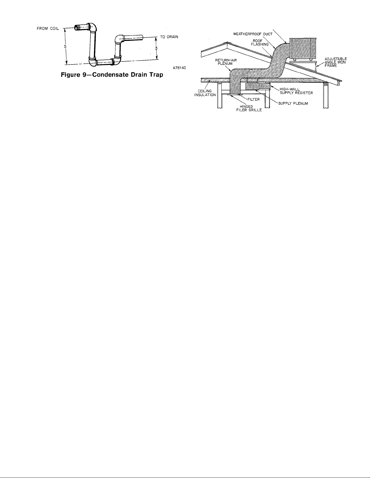
It is recommended that a 3-inch trap be installed in the
drain line to avoid improper drainage and to prevent leakage
of indoor air to the outdoors. See Figure 9. Make sure that
the outlet of the trap is at least 2 inches lower than the unit
drain pan connection to prevent the pan from overflowing.
-3-
Page 4

TABLE ll-ELECTRICAL DATA-MODEL 542E-SIZES 024 THRU 042
MODEL
SIZE
SERIES A A A
Unit Volts-Phase (60Hz)
Operating Voltage Range 197-253 197-253 197-253 187-253
Total Unit Amps
Max Branch Circuit Fuse Size (Amps) 30
Unit Ampacity for Wire Sizing 20.2 27.5 29.2
Minimum Wire Size (AWG)*
Maximum Wire Length (Ft)* 115 85 80 95
024
208-230-1
16.7
10
030 036
208-230-1
22.7
45
10
208-230-1
542E
208/230-3
23.9 14.8
45 25
10
17.8
12
042
A
230-1
207-253 187-253
28.7 21.0
50
34.9
8
112
208/230-3
40
25.2
10
107
TABLE MI-ELECTRICAL DATA-MODELS 542E048, 542D060, & 542E060
MODEL
SIZE
SERIES
Unit Volts—Phase (60Flz) 230-1
Operating Voltage Range 207-253
Total Unit Amps
Max Branch Circuit Fuse Size (Amps) 60
Unit Ampacity for Wire Sizing 38.9
Minimum Wire Size (AWG)* 8 10
Maximum Wire Length (Ft)* 101 100
*Only use copper wire for field connections to unit. Wire size is based on 60 or 75°C copper conductor at 86°F (30°C) ambient tempera
ture and ampacity shown in fable. If other than 60 or 75°C copper conductor is used, if ambient temperature is above 86°F, or if voltage
drop of wire exceeds 2% of unit rated voltage, determine wire size from ampacity shown and the National Electrical Code. Wire lengths
shown are measured one way along the wire path between unit and service panel for minimum voltage drop.
USE SPREADER BARS TO PROTECT UNIT
31.9
542E 542E
048 060
A A
208/230-3 460-3
187-253
22.4 10.9 40.9 26.1
45 20 60
27.1
414-506 207-253 187-253
13.2
14
181 123
USE SPREADER BARS TO PROTECT UNIT
230-1
49.8
6 8
542D & 542E
208/230-3
50
31.3
137
060
A
460-3
414-506
13.7
25
16.4
12
229
ONE INCH FROM PLENUM FOR
PROPER FIT ON CURB AND PLATFORM
CHAIN RETAINER FOR
PROPER BALANCE
Figure 7—542D060 Suggested Rigging
Prime the trap with water and check the condensate line for
leaks.
CAUTION; Do not undersize the condensate drain line.
During the heating defrost cycle, defrost water from the
melting ice on the outdoor coil flows through the slots in the
heat pump base directly below the outdoor coil. If a field-supplied drain pan is to be used to catch the defrost water, this
pan should be at least 2 inches high and extend at least 2 in
ches beyond the width and length of the unit.
If the installation requires draining the condensate and/or
defrost away from the unit, connect a minimum of 7/8-inch
OD copper tubing, 3/4-inch galvanized pipe, or 7/8-inch
plastic pipe. The drainage lines should pitch downward at a
slope of at least 1 inch in every 10 feet of horizontal run.
Both condensate and defrost water can be drained directly
onto the roof in rooftop installations where permitted or
onto a gravel apron in ground-level installations. When a
gravel apron is being used, it should extend at least 24 in
ches around the mounting pad to ensure proper drainage.
III. DUCT CONNECTIONS
Flanges are provided on the 542E supply- and return-air
A79148
Figure 8—542E Suggested Rigging
openings on the side of the unit. See Figure 3 for connection
sizes and locations. See Figures 10 and 11 for illustrations of
typical installations.
Flanges are provided on the 542D supply- and return-air
openings on the bottom of the unit. See Figure 4 for connec
tion sizes and locations.
NOTE: The minimum installation requirements of the duct
system must be in accordance with the standards of the Na
tional Fire Protection Association for installation of air con
ditioning and ventilating systems of other than residence
type, NFPA No. 90; or residence type, NFPA No. 90B; and/or
local codes and ordinances.
CAUTION: When the duct system fastening holes are being
drilled into the 542E side instead of the unit duct flanges
provided, use care to avoid puncturing the coil tubes.
The following criteria must be followed when selecting, siz
ing, and installing ductwork:
1. When electric heater is installed, a minimum clearance
of one inch to combustible materials must be main
tained for the first 36 inches of duct.
2. It is recommended that flexible connectors be used be-
-4-
Page 5
tween the ductwork and unit to prevent transmission of
vibration. The duct system can be screwed or bolted to
the unit duct flanges. Suitable gaskets should be used to
insure an airtight seal. When a supplemental electric
resistance heater is being used, use fireproof material
for the connector between the ductwork and unit sup
ply-air duct flange. If flexible duct (which is not heat re
sistant) is being used, use a sheet metal duct sleeve in
side the flexible duct for at least the first 36 inches of
duct.
3. An external field-supplied air filter must be installed in
the 542E return-air ductwork. Recommended filter sizes
are shown in Table I. Filters should be installed where
they are easily accessible for service.
NOTE: Model 542D has factory-supplied high-capacity air
filters. High-capacity air filters are also factory-supplied
when the accessory plenum, horizontal economizer, or highcapacity filter rack is being used with Model 542E.
4. Avoid abrupt duct size increases of decreases.
5. Size all ductwork for required heat pump airflow.
6. Adequately insulate and weatherproof all ductwork
located outdoors. Ducts passing thru an unconditioned
space must be insulated and covered with a vapor bar
rier in accordance with the latest issue of SMACNA and
NESCA minimum installation standards for heating
and air conditioning systems.
7. Secure all ducts to the building structure.
8. All openings in the building structure must be properly
flashed, weatherproofed, and vibration-isolated in ac
cordance with local codes and good building practices.
IV. ELECTRICAL CONNECTIONS
WARNING: Tlit- iiiiit l aliinet have.-in uninrerrupted or
unbroken electrical ground to mininii/o por.ional injury if aii
electrical fault should occur. This may consist of elec.rical
wire connected to the unit ground lug in the control com
partment, or conduit approved for electrical ground when in
stalled in accordance with the National Electrical Code and
local electrical codes. A failure to follow this warning can re
sult, in the installer being liable for the personal injury .of
others. ■ , ■ ,
CAUTiON: A failure to follow these precautions could result
in danaage to the. unit being installed:
1. All electrical connections must be made in accordance
with the National Electrical Code and local electrical
codes governing such wiring.
2. Copper conductor is the only type of wire that is to be
connected between the field-supplied electrical discon
nect switch and the unit. DO NOT USE ALUMINUM
WIRE.
3. High-voltage power to the unit must be within the
operating voltage range indicated on the unit rating
plate. On 3-phase units, phases must be balanced within
2%. Consult the local power company for correction of
improper voltage and/or phase balance.
4. When the low-voltage control wires are run in the same
conduit as the high-voltage wires, the low-voltage wires
must be insulated for the highest voltage contained
within the conduit.
ACOUSTIC a INSULATION
DUCT LINER
Figure 10—542E Typical Rooftop
Installation on Pitched Roof
5. When drilling thru any panel to mount electrical hard
ware, conduit, etc; ensure that the drill does not damage
internal components.
6. If aluminum ,conductors are used between the electrical
service panel (power source) and the field-supplied
electrical disconnect switch, the wire gauge selected
must have a current capacity that is not less than the
; copper wire specified and must not create a; voltage drop
in excess of 2% of the unit rated voltage.
A. High-Voltage Connections
A separate electrical line with a field-supplied, waterproof,
fused disconnect, switch mounted at, or within sight of, the
unit must be used for this installation. Refer to the unit rat
ing plate for maximum fuse size and minimum amps
(ampacity) for wire sizing. Tables II and III show recom
mended wire sizes and lengths based on rating plate data.
NOTE: The field-supplied fused disconnect may be mounted
over the unit high-voltage inlet hole directly on the control
corner panel adjacent to the blower access panel. See Figure
3 or 4. Be sure that the disconnect box does not interfere
with the removal of the blower access panel. When mount
ing the disconnect box, align the knockout in the box with
the unit high-voltage inlet hole. Route the wiring from the
disconnect box thru the aligned holes. This connection must
be watertight to prevent water from entering the control
box.
Proceed as follows to complete the high-voltage connections
to the unit:
1. Run high-voltage power leads from fused disconnect
thru high-voltage inlet hole in control corner panel. See
Figure 3 or 4.
2. Connect ground lead to chassis ground connection, and
connect high-voltage power leads to unit high-voltage
pitgail leads. Single-phase units have two black pigtail
leads. Three-phase units have two black and one red pig
tail lead. See Figure 12, Figure 13, and unit wiring
label. Use a suitable wire splice connector or wirenut to
make each high-voltage connection. Tape each com
pleted connection.
B. Low-Voltage Connections
Recommended heat pump room thermostats for heat pump
operation with or without supplemental electric heaters are
P/N 34427DP115 (subbase included) for automatic system
changeover and P/N34427DP118 (subbase included) for
manual system changeover. These thermostats have an
emergency heat (EM. HT.) switch and red indicator light.
Heat pump room thermostat P/N 34427DP87 (subbase in
cluded) can be used for heat pump operation without supple
mental electric heaters. This thermostat provides for
manual system changeover and does not have an emergency
heat switch.
-5-
Page 6

LOW-PRESSURE
SERVICE FITTING
ACCUMULATOR
ACCUMULATOR
FUSIBLE
PLUG
DEFROST
THERMOSTAT
METERING
DEVICE
Figure 11—542E Typical Ground Level Installation
Into Crawl Space
DUAL CAPACITOR
REVERSING VALVE
ASSEMBLY .
HIGH-PRESSURE
SERVICE FITTING
(COMPRESSOR a
FAN MOTOR)
BLOWER MOTOR
RELAY
------
.Si LOW-VOLTAGE
-
--------- \ TERMINAL
A79242
BLOWER MOTOR
CAPACITOR
DEFROST
RELAY
DEFROST
TIMER
TRANSFORMER
\ BOARD
LOW-VOLTAGE
INLET HOLE
CHASSIS
GROUND
CONNECTION
LOW-PRESSURE SWITCH
INDOOR COIL DRAIN PAN
I MPT PLASTIC DRAIN FITTING
^(SHIPPED TAPED INSIDE
COMPRESSOR COMPARTMENT)
Figure 12—Partial Side View With Compressor & Control
Access Panels Removed (Model 542E036, 208V-230V—1)
QUICK-START PTC
THERMISTOR
COMPRESSOR
HIGH-VOLTAGE
PIGTAIL LEADS
FIELD SPLICE
FIELD-SUPPLIED
FUSED DISCONNECT
SWITCH
Figure 13—Field High-Voltage Connections
-6-
A79244
HIGHVOLTAGE
PIGTAIL
LEADS
A79243
Page 7

Figure 14—Field Low-Voltage Connections Using Room
Thermostat P/N 34427DP115or P/N 34427DP118
HEAT PUMP
LOW-VOLTAGE
TERMINAL
BOARD
Figure 15—Field Low-Voltage Connections Using Room Thermostat P/N 34427DP87
Mount the room thermostat on an inside wall in the space to
be conditioned. The thermostat should be approximately 4 or
5 feet above the floor and located where it will not be sub
jected to either a cooling or heating source, or direct ex
posure to sunlight.
Use No. 18 AWG “color-coded” insulated wires to make the
low-voltage connections between the thermostat and the
unit. If the thermostat is located more than 100 feet from
the unit as measured along the low-voltage wires, use No. 16
AWG wire.
A grommeted low-voltage inlet hole has been provided in the
control panel adjacent to the control access panel. See
Figure 3 or 4. Run the low-voltage thermostat leads thru the
inlet hole and to the low-voltage terminal board. See Figure
12. Complete the low-voltage thermostat connections as
shown in Figure 14 or 15, depending on which recommended
room thermostat is being used.
C. Heat Anticipator Settings
The recommended room thermostats have a fixed heat antic
ipator for heat pump heating. When using an accessory
electric heater to provide supplemental heat and emergency
heat capability for the system, see the Installation Instruc
tions packaged with the heater for setting the adjustable
second-stage heat anticipator.
V. PREPARING UNIT FOR STARTUP
WARNING/DANGER: A failure to Inllow the-e in.struclion.'
could roiult in seiiou.-< person;.I injury:
1. Follow recognized safety practice.- and wear protective
goggles when checking or .servicing the refrigerant
2. Do not oper.ali' the compres.=or or pro\ ide any electric
power to thi- unil unles.s compre-.'or tormin.il co\ or i.- in
place and secured.
0. Do not rerno\e the compres.-or terminal cu\er iinli! all
electrical source- lia\e been di.sronnected.
1. If a rcl'ngeranl leak is su.-pi'Cted ,iround the com)!re.--or
terminals, relie\e all pres-utv from the -v-tem before
touching or di-ttirliing anything inside the tciminal
■7). .Sy-tem contani.- ml :ind r efri.ger.int under pre.-.-tire. De
not use a torch to remove any component To remote a
component, wear protective goggles and [U'oceed as fol-
a. Shut oil electrical power to unit.
li. Reliete all pressure from sy-tem.
c. (7ut component connectin.g tubing with tubing ciit-
ti'i- and remove component from unit.
d. When nece.ssary. un.-weat remaining tubing -tubs
carefully. Oil may ignite when exposed to torch
ÎiisilïiïiSilSijîliSîiiïiiliillS^^
Proceed as follows to prepare the unit for initial startup:
1. Read and follow instructions on all WARNING, CAU
TION, and INFORMATION labels attached to the unit;
for example, blower rotation labels etc.
2. Visually inspect for oil at all refrigerant tubing connec
tions and on unit base. Detecting oil generally indicates
a refrigerant leak. Leak-test all refrigerant tubing con
nections, using electronic leak detector, halide torch, or
liquid-soap solution. If refrigerant leak is detected, see
Section VI, “Refrigerant Leaks,” in these instructions.
-7-
Page 8

3. Make certain all field and factory wiring connections
have been completed and are tight.
4. Inspect all supply ducts and grilles to be sure they are
open.
5. Check for correct position of outdoor fan blade in fan
orifice. Blades should clear fan motor by no more than
1/4 inch.
6. Check to be sure air filters are in proper place.
7. Fill condensate drain pan with water to assure proper
drainage.
8. Make certain all tools and miscellaneous loose parts
have been removed.
9. If coil fins have been damaged during shipping and han
dling, carefully straighten fins with a fin comb.
10. Replace all access panels. Unit is now ready for initial
startup.
VI. REFRIGERANT LEAKS
In rare instances when the factory refrigerant charge has
been lost because of a shipping damage leak, or when a re
frigerant leak has been found, proceed as follows:
1. Locate leak and ensure that refrigerant system
prressure has been relieved.
2. Repair leak following accepted practices.
3. Add a small charge of R-22 refrigerant to system and
leak-test unit.
4. If additional leaks are not found, evacuate refrigerant
system.
5. Charge unit with R-22 refrigerant to exact amount
shown on unit rating plate, using volumetric charging
cylinder or accurate scale.
NOTE: It is recommended that a filter-drier be installed
whenever the system has been open for repair. If a filterdrier has been installed, be sure to add enough extra R-22 to
compensate for the internal volume of the filter-drier.
VII. STARTUP AND ADJUSTMENTS
CAUTION: Ho nm lu'iiperanv .-.afct\ di'\ue.s wln-n oiu-nii
ing the unit. Do not operate the compressor until electric
power has been applied to the heat pump for a minimum of 4
hours to ensure that the off-cycle crankcase heater has sufii-
cii.-Miiy uyrnii.'d I hi’ l.■ll[llV"'^■'■.мll■ oil t(.i fit-e niosi of ilu- ac
cumulated refrigerant.
A. Checking Unit Operation
The heat pump should be started and checked for proper
operation as follows:
1. Set room thermostat SYSTEM switch to OFF position.
Observe that indoor blower motor starts when FAN
switch is placed in ON position and shuts down when
FAN switch is placed in AUTO position.
Proceed as follows to evaluate the system performance and
refrigerant charge level:
2. Place SYSTEM switch in COOL position and FAN
switch in AUTO position. Set thermostat temperature
setting to “call” for cooling. Compressor, outdoor fan,
and indoor blower motors should start. Observe that
unit shuts down when thermostat temperature setting
is satisfied. Wait 5 minutes for pressues to equalize.
3. Place SYSTEM switch in HEAT position and leave FAN
switch in AUTO position. Increase room thermostat
temperature setting gradually unitl thermostat “calls”
for heat. Compressor, outdoor fan, and indoor blower mo
tor should start. If supplemental electric heater is being
used in the system, increase room thermostat tempera
ture setting an additional 6 degrees. The supplemental
electric heater should energize. Set thermostat setting
below room temperature and observe that heater
deenergizes and that heat pump shuts down.
4. If supplemental electric heater is being used in the sys
tem, leave FAN switch in AUTO position, SYSTEM
switch in HEAT position, and move emergency heat
switch from NORM, position to EM. HT. position. Set
room thermostat temperature setting above room tem
perature. Observe that all supplemental electric heat is
energized, that indoor blower motor starts, and that
emergency heat indicator bulb lights. When thermostat
temperature setting is satisfied, observe that heater
deenergizes and that blower motor stops; however,
indicator light should remain on as long as emergency
heat switch is in EM. HT. position.
5. If autochangeover thermostat P/N 34427DP115 is
being used, place both SYSTEM and FAN switches in
AUTO position. Observe that heat pump operates in
heating mode when thermostat temperature selector is
set above room temperature, and operates in cooling
mode when selector is set below room temperature.
B. Checking and Adjusting Refrigerant Charge
The refrigerant system has been fully charged with R-22 re
frigerant, tested, and factory-sealed. The factory charge is
the correct charge for optimum performance for most in
stallations; however, this charge may require a slight
adjustment for some installations to assure full rated per
formance.
An operating pressure/temperature tag (also see Tables IV
and V) is fastened inside the unit compressor compartment.
This tag is provided so that the refrigerant charge can be
evaluated by checking operating pressures and tempera
tures. This method of checking is sufficiently accurate to
determine the adequacy of the refrigerant charge in the sys
tem when the conditions and system components are nor
mal; however, it does not solve or fix system abnormalities.
The evaluation indicates whether the refrigerant charge
needs a slight increase or decrease to establish the correct
operating pressures for the system at the time of checking.
The level of refrigerant operating charge determines how
efficiently and economically the unit will operate. An over
charged or undercharged unit will lead to insufficient heat
ing and cooling mode capacity, high operating costs, and the
possibility of premature compressor failure.
When checking the refrigerant using the temperature/pressure evaluation method, adhere to the following criteria:
1. Check refrigerant charge in cooling mode when outdoor
temperature is above 65°F.
2. Check refrigerant charge in heating mode when outdoor
temperature is below 65°F.
3. For best results, do not operate unit continuously for
more than 10 minutes if for any reason charge must be
checked in opposite mode above or below 65°F.
1. Remove caps from low- and high-pressure service fit
tings. See Figure 12.
2. Attach low- and high-side pressure gauge hoses to lowand high-pressure service fittings, respectively. Hoses
must have valve core depressors. Gauges should be cali
brated for accuracy.
3. Set room thermostat below room temperature to start
cooling operation or above room temperature to start
heating operation, depending on outdoor temperature.
Allow unit to operate until conditions stabilize and pres
sures level out.
4. Determine and record these conditions:
a. Low- and high-side pressure.
b. Dry-bulb temperature of inlet air at outdoor coil.
c. Temperature of inlet air at return-air grille—wet
bulb if operating in cooling mode or dry bulb if
operating in heating mode.
-8-
Page 9

TABLE IV-HEATING PERFORMANCE PRESSURES
Air Temp at
Indoor Coil
Inlet l°F DB|
Pressure
Designation
(Psig)
60 50 40
65 High Side 250 229 209 190 172 155 140 127 238 218 201
Low Side
69 59
70 High Side 268 243 220
Low Side 70 60 50 42 34
75
High Side 280 256 233 211 190 172 155
Low Side
71 61 51
5426024
Air Temperature at Outdoor Coil F°0B Air Temperature at Outdoor Coil °F0B Air Temperature at Outdoor Coil °FDB
30 20 10 0
49 41 33 25 18 14
199 180 162 147 134
26 19 15
-to
60 50 40
251
266 246 226
140
71
72 61 51
43 35 27 20 16 73 62
50 41 32
60
211 195 179
231
52 43
542E030 542E036
30 20 10 0 -10 60 50 40 30
184 169 155 144 134 232
24
18 13
165 153 142
42 33 25 19 14 65
207 190 176 162 151 261
34
26 20
15 66
214
198 183 170
64 52 46 38
247 230 213
53 47 39 31
225
243
54 48 40 32 26
198 184 171 161 152
209 195 182 171 162
20 10 0 -10
158 149 142
31 25 18 13
25 19 13
19
14
Air Temp at
Indoor Coil
Inlet (°F OBI
65
Pressure
Designation
High Side
Low Side
70 High Side
Low Side 72 63 51
75
High Side 283 266 243 218 194 180 166
Low Side
(PsigI
60 50 40 30 20 10 0
254 234
71 62
250 230
268
73 64
542E042 542E04B
Air Temperature at Outdoor Coil °FDB Air Temperature at Outdoor Coil °FDB
216 193 171 159 148 136 262 237 214 193
50 42 32
24
205 183 169 156 144 278 251 226
43 33
25
52 44 34 26 19 14 66 58
TABLE V-COOLING PERFORMANCE PRESSURES
Air Temp at
Indo or Coil
Inle t (°FWB I
Air Temp at
indo or Coil
Inle t l°F WB I
Pressure
Des ignatio n
55 High S ide 157 174 190
50 High S ide 162 179 195 212 228
65 High Side 168 185 200 216 232 247
70
75 High S ide 175 192 209 227 242 260 278 294 315 336 164
55 High Side 165 179
60 High Side 169
65
70
75
IPsi gi
Low Side 58 59
Low Side
Low Side
High Side
Low Side 77 78 79
Low Side 84 85
Pressure
Des ignatio n
Low Side
Low Side 64 66
High Side 173 187
Low Side 68
High Side 177 191
Low Side 72
High Side 181 196
Low Side
173 191
IPsi gi
75 B O B5 90 95 10 0 10 5
65 70
60 61 62 63 64 66
64 65 66 67 68 69 70 71 73
70 71 72 73 75 76 77 78 79 80 67
206 223 239
86 87 88
70 7 5 80 85 90
65
192 206 222
60 62 63
183 196 210 226
67 69 70 72
201 215 231 246 263 280 298
69 71 73
205 220 235 251 268 285 303
73 75
210 225 240 256 273 290 3 08
76 77 79 81
542 E02 4
Air T em p a t Ou tdo or C oil i°F D BI
207 224 240 258 276 293 313
244 261 279 296 315
264
270 288 304 324
253
80
81 82 83
91 93 94 95
90
542 E04 2 542 E04 8
Air T em p a t Ou tdo or C oil (°F O B)
65 67 68 70 72
77
95 1 00 1 05 11 0
237 254 270 289 308 178 192 207 224 238 255 272 291 308 330 176 189 202
241 258 275 293 312
74 75 77 79 65 66 67 69 70 72 74 76 78 80 63 65 66 67 68 70
74
78 79 81 83 69 70 71 73 74 76 78 80 82 8 4 67 69 70
76
80 82 83 85 87 73 74 '75 77 78 80 82
78
82 84 86 87 89 91
67
298 317
282
84 86 87
74 75 61 62 63 65 66 68 70 72 74
5420060 S 542E060
Air Temperature at Outdoor Coil °FDB)
-10
18 14
60 50 40
64
56 48 40 33
20 10 0 -10
30
174
144 134 268
158
26
19
204 184 166 154 146
18 14
153
65 57 49 41
290 266 242
34 27
20 13
220 201 184 169 158 298 268
50 42 35 28 21
542 E03 0 54ZE036
110
65 70 75 60 85 9 0 95 100 10 5 1 10 65 70 7 5 8 0 85 90 95 100 105 110
150 166 181 196 212 226 246 264
68
60 62 63 65 67 69
153 169 185 200 216 230 250 268
74
63 65 66 68 70 72 75 77 79 81 69 ' 71 72
157 173
160 177 192 208 224 240 259 277 295 315 192 207 223 239 255 273 290 308 326 346
70
180 196 212 2 28 244 264 282 300 320 196 212 228
74
65
70 7 5 80 85 9 0
183 197
317 188 203
322 193 208
327 198 214
77
Air T em p a t Ou tdo or C oil i°FD BI Air T em p a t Ou tdo or C oil l°FD BI
282 302 182 196
71
73 75 77 67 69 70 72 74 75 76 78 79 8 1
286 306 185 199
204 220 235 255 273
188
69 70 72 74 76 79 81 83 85 71 73
74
72
76 78 80 83
76 78 80 82
Air T em p a t Ou tdo or C oil l°F D BI Air Te mp at O utd oor Co il l°FDB |
212 229 243 260 277 296 314 335 180 193
235 249 266 283 302 320
218
240 254 271 288 307 326 345 191 205 219 234 250 266 283
223
229 246
78 80 81 8 3
84 87
260 277 294 312 332 350 198 212
84 86 88 90 92 76 77 79 80 82
291 311 188 203
85 87
89 91 93 79
95
100 10 5 110 6 5 70
84
86 88
60 50
13 66
284 252
67 57
14
68 58
74
89
59 61 62 63 65 67 68 70
76
340 185 198
71
40 30 20
210 186 166 151 142 136
238
47 39 32
56
224 198 178
48 40
238 212
49
211 227 242 259 276 294 312 332
215 231 246 263 280 298 316 336
74
219 235 251 268 285 303 321 341
74
76 78
77 79 81 83 84 86 88 89
76
244
81 83 84 86 88 89 91 93 95
75 6 0 B5 90 95 100 105 11 0
217 233
207
222
212 227 242 259 275 292 310 329
71 72 74 75 76 78 80
74 75 77 79 80 81 83
73
227 242 258 274 292 310 328 346
32 25 19 13
190 174 162 156
41 33 25 20
77
76
79 80 82
80
81 83
260 278 296
542 006 0 8 542E060
266 283 300 320
249
237 254 270 287 305
71
84
85
10
0 -10
24
19 13
164 154 146
14
83
85 86
314
332 352
72 74
324
75 77
73
301 319 338
85
87
89 91
5. Evaluate system performance and refrigerant charge
level by comparing recorded readings with unit operat
ing pressure/temperature tag.
6. When necessary, make slight adjustment to refrigerant
charge. If a substantial adjustment is indicated, deter
mine abnormal condition in system that is causing inac
curate readings, such as insufficient airflow across
either or both coils.
CAUTION: If it i.-^ dcri-rrniin-d thaï ihe problem i' ai; o\cr
charged or undercharged unit’when operating in the heat
ing mode, the refrigerant system should be evacuated and
recharged by adding the exact amount of R-22 refrigerant as
shown on the unit rating plate. A volumetric charging
cvliiuler or ac'. uraie .•fcoie should be u.~ed. \V her. operating in
the cooling mode, the operatiiig pre.ssiin' tempierature tag
may be used to adjust the charge.
C. Indoor Airflow & Airflow Adjustments
Model 542D and 542E units are equipped with direct-drive
-9-
blower motors. All motors have a high- and low-speed con
nection except for 460-V motors which have only a high
speed connection.
The system airflow for all units (except 460-V) can be
changed, when necessary, by changing the blower motor
speed connection from the factory setting to the unused
speed connection. The factory setting is indicated on the
unit wiring label.
CAUTION: The recommended airflow is 400 to 450 ftVmin
per each 12,000 Btuh of unit capacity. Inadequate airJlmv
can cause unsatisfactory operation and performance. Cer
tain unit./heater combinations can only be used with high
speed blower operation. See electric heater information
Table VI shows the air delivery performance of all units at
various external static pressures. Determine the airflow for
the system being installed as follows:
1. Start unit and measure static pressure in duct system at
unit.
Page 10

TABLE VI-AIR DELIVERY (FtVMin) AT INDICATED EXTERNAL STATIC PRESSURE & VOLTAGE*
Blower
Model
542E024 Low
542E030 Low
■ 542E036
542E042 Low 208
542E048
542E060 Low
542D060 Low
*Air delivery values shown for Model 542D060 are with factory-supplied air filter and plenum. Air delivery values shown for all sizes of
Model 542E are without air filter.
t Heating airflow values are with a dry coil. Cooling airflow values are with a wet coil.
NOTE: Shaded portions of this table fall below 350 ft^/min per 12,000 Btuh of rated cooling
airflows below this point. Dashes are used in those areas of the table that fall beyond
Motor
Speed
High
High
Low 208 Heating
High
High
Low
High
High
High
Opera
ting
Voltage
208
230
208 Heating
230
208 Heating
230 Heating 1070 1050 1025
208 Heating
230
230 Heating
208 Heating
230 Heating 1850
230
208 Heating
230
208 Heating
230 Heating
208 Heating
230 Heating
460 Heating
208
230 Heating
208 Heating
230 Heating
460 Heating
208 Heating
230
208 Heating 2270
230 Heating
460 Heating
Applica-
tiont
Heating 880
Cooling 850
Heating
Cooling
Cooling 985 940 890
Heating 1070
Cooling
Cooling 980 945 910
Cooling
Cooling
Heating
Cooling 1245 1225 1200
Cooling
Cooling 1400 1350
Cooling
Cooling
Heating 1400
Cooling
Heating 1655
Cooling
Cooling
Heating
Cooling
Cooling
Cooling
Cooling
Cooling
Cooling
Heating
Cooling
Cooling
Cooling
Cooling
Cooling
Cooling
Heating
Cooling 2085
Cooling 2190
Cooling 2395
Cooling 2165
0.0
965 925 880
940 900 855
1015 970 920
1040 1000 955
995 965 930
1055 1030 1005
1165 1145 1125
1150 1130 1105
1260 1245 1225
1280 1235 1185
1225 1185 1140
1485 1435
1685 1630 1575
1565 1510
1670 1615
1370 1330
1615 1565
1895
1825 1770
2125
2030 1970
1690
1650 1595
1905
1860
2005 1955
1955
2270 2195
2180
2070 2000
2000 1930
1860 1850
1840 1830
2250
2180 2135
2355 2315
2285 2240
2700 2625
2550 2475
2290 2260
2240 2205
1840 1825
1820 1800
2160
2550
2225
0.1 0.2 0.3
835 790
810 770
1030 985
1785 1720
1360
1610
1840
■ 2065
1635
1855 1800
1810
1905
2110
2205
2110
2030
2225
2135
2465
2315
2185 2140 2090
2115
External Static Pressure—Inches wc
/i 740 690
725,';'
835
810
870
840
940
910
890
865
995
970
1095
1075
1200
1170
1135 1080
1380 1325
1300
1455
1560
1315
1280
1560 1505
1510
1780
1710
2005 1935 1860
1905
1575 1510 1440
1535
1755 1690
1900
1850 1790
2120
2040 1960
1925
1855 1775 1690
1840
1820
2160 2110
2085
2270 2220 2165
2190
2550
2395 2315
2225
2165 2115 2065
1805
1765
2050 1990 1915
1970
2170 2105 2035
2075
2380 2285 2180
2225 2120 2010
2065 2000 1915
1095
1250 1190
1510 1440
1395 1325
1650 1575
1495 1425
....
1265 1205
1230 1165
1450 1380
1715
1645 1570
1835 1760
1475 1405
1740 1675
1845 1780
2040 1955
1845 1760
1825 1805
1800 1765
2030 1970
2135 2075
2465 2380
2185 2140
1770 1710
1705 1600
1900 1815 1700
2005
0.4
; . 675;
780 : 720
755 700 635
815 , 750 ' ; : 685
785 ; 730 ,S65 '
885
855
845
820
960.
930
1065
1035
1165
1135
1040
1265
1435
1645
1625
1725
1880
2050
2220 2120
1920
2025
capacity. Indoor coil icing may occur at
the capability of the indoor blower motor.
f
0.5
■ 630 ; 565
'.615
830 '.765.; :■ : : 680
800 735
785 705
760 680
915
880 800
1020 955 845 ,
980 900
1125
1080
1020
985
1200
1125
1360
1250 1160
1490
1345 1250
1130
1085 955 —
1360
1,305 1205
1570
1490 1395
1775
1675 1575
1360 1270
1325
1600 1510
1545
1705 1625
1650
1870
1785
1665
1595
1770
1705
1990
1900
2105
2005
2285
2090
2000
1585
— —
1830
1950
1800
2055
1860
1940
1770
0.6
: 550 :
:655„'" "■ 5.75'"‘i
840 730
1065 970
1005
955
920
1115 1025
1050
1275
1395
1015
1270 1140
1480 1365
1685 1570
1230
1445
1560
1765 1650
1685
1560 1425
1490
1710
1600 —
1915
1815 1700
2035
1920
2175 2055
2005
2025
1915
-
1695 —
...
1815
—
1905 -
—
1790 —
—
0.7
470 :
465 :
560 ; :
605
585 ;;
660
590 '
560
680
770
875
875
850
970
1160
1045
1280
1100
1050
1270
1440
1140
1100
1370
1290
1510
1430
1570 ,
1355
1575
1830
1950
1800
1860
1940
1770
—
—
■
—
—
—
-10-
Page 11

2. Refer to Table Vl and determine airflow at static pres
sure measured.
When an accessory electric heater is being used, the system
airflow can also be determined by measuring the tempera
ture rise through the unit and using the following formula:
AIRFLOW (fts/min) = i X Y
where,
KW = Heater nominal KW at 240 or 480V
TR = Measured température rise
Y =
200V
2195 2374
NOTE: Value Y varies with the operating voltage at the heater.
Interpolate to determine the value of Y for voltages not
shown.
D. Unit Controls and Safety Devices
208V 220V
440V 460V
2655 2902
230V
240V
480V
3160
1. High-Pressue Relief VaZue—This valve, which is located
in the compressor, opens when the pressure differential
between the low and high side becomes excessive.
2. Compressor Internal Overload—Hhis overload, which is
located in the compressor, interrupts power to the com
pressor when the current and internal temperature
become excessive. It automatically resets when the
internal motor temperature drops to a safe level. It may
require up to 60 minutes or longer for this overload to
reset; therefore, if an internal overload is suspected of
being open, disconnect the electrical power to the unit
and check the circuit thru the overload with an ohmmeter or continuity tester.
3. Low-Pressure Switch—This switch with automatic reset
interrupts the compressor control circuit when the re
frigerant high-side pressure becomes too low. It protects
the compressor from damage attributable to loss of the
refrigerant charge.
4. Time/Temperature Defrost System—The defrost control
system consists of a defrost timer, a defrost thermostat
switch, and a defrost relay. The system initiates defrost
cycle operation every 90 minutes if a coil icing condition
exists. See the defrost cycle sequence of operation in
Section VIII.
5. Crankcase Heater—This device prevents overdilution of
compressor oil with refrigerant during shutdown
periods, thereby extending the life of the compressor.
See the crankcase heater sequence of operation in Sec
tion VIII.
6. Compressor Quick-Start Componenis—These components
are used with all single-phase units to improve com
pressor starting characteristics.
7. Outdoor Fan Thermostat—This control, which is
featured on all 3-phase units, maintains the proper cool
ing mode condensing temperature by switching the
outdoor fan motor to high- or low-speed operation. Lowspeed fan operation permits low-ambient cooling opera
tion down to 40°F outdoor temperature.
Vili. SEQUENCE OF OPERATION
Do not leave the installation until the heat pump has been
observed throughout one or two complete cycles. The in
staller should make certain during this time that all compo
nents are operating in correct sequence.
The sequences of operation described in this section pertain
to all 208/230-volt, 3-phase units; however, the sequence of
operation of single-phase and 460-volt units is Very similar.
Refer to the line-to-line wiring diagram in Figure 16.
NOTE: Although the actual unit wiring may vary slightly
from that shown in Figure 16, the sequence of operation will
not be affected. The sequences of operation described in this
section pertain to a typical system using room thermostat
P/N 34427DP115 or P/N 34427DP118 for system control,
and using an accessory electric resistance heater for supple
mental heat.
NOTE: The indoor blower motor will operate continuously,
regardless of the room thermostat SYSTEM switch position,
when the FAN switch is in the ON position. The ON position
of the FAN switch keeps the circuit through blower relay
coil 2A closed and the coil energized. When the FAN switch
, is in the AUTO position, the blower operates only when the
system is started by the room thermostat demand for heat
ing or cooling.
A. Crankcase Heater Operation
Compressor crankcase heater llA is connected across nor
mally open compressor contractor 2D contacts between 13
and 23. When electric power is supplied to the heat pump,
and the unit is not operating in either the heating or cooling
mode, a completed circuit between power legs LI and L3 per
mits current to flow through one leg of compressor motor 3F
windings and through crankcase heater 11 A. The high
electrical resistance of the crankcase heater causes the
heater to heat up, while the compressor motor windings
serve only as a means of completing the circuit between LI
and L3.
When the heat pump receives a “call” for either heating or
cooling, normally open compressor contactor 2D contacts be
tween 13 and 23 are closed. (See heating and cooling
sequences of operation in this section.) Electric current,
which always follows the path of least resistance, now flows
through the closed contacts and through both compressor
motor 3F and outdoor fan motor 3D1. The crankcase heater,
which offers a much higher electrical resistance than the
two motors, receives virtually no electrical current as long
as the contactor is energized.
B. Cooling Operation
With the room thermostat SYSTEM switch in COOL posi
tion and the FAN switch in AUTO position, the cooling
sequence of operation is as follows:
When the room temperature rises to within 2 degrees of the
room thermostat temperature setting, the thermostat cool
ing operation bulb “makes” and thermostat terminal R is
connected to thermostat terminal 0. This completed circuit
through the thermostat completes the circuit through unit
terminal 0. Reversing valve solenoid coil 5B and outdoor fan
relay coil 2C are now connected across the 24-volt secondary
of unit transformer IB.
Energized solenoid coil 5B switches the reversing valve from
the normal heating mode position to the cooling mode posi
tion. Energized outdoor fan relay coil 2C closes its set of nor
mally open contacts between 1 and 3, and opens its set of
normally closed contacts between 1 and 2, permitting twospeed outdoor fan motor 3D1 to operate on either high- or
low-speed depending on the outdoor ambient temperature.
NOTE: When the contacts of outdoor fan relay coil 2C are in
their normal heating mode positions as shown in Figure 16,
fan motor 3D1 operates on high speed, regardless of the out
door ambient temperature.
The heat pump is now in a “standby” condition and ready to
operate in the cooling mode when the room thermostat
“calls” for cooling.
When the room temperature rises slightly above the ther
mostat temperature setting, the thermostat cooling bulb
“makes” and thermostat terminal R is automatically con
nected to thermostat terminals G and Y. These completed
circuits through the thermostat connect indoor blower relay
coil 2A (through unit terminal G) and compressor contactor
coil 2D (through unit terminal Y) across the 24-volt sec
-11-
Page 12

ondary of unit transformer IB.
Energized indoor blower relay coil 2A closes its set of nor
mally open contacts between 1 and 3, completing the circuit
through indoor blower motor 3D2, and the motor starts.
Energized compressor contactor coil 2D closes its normally
open contacts between 13 and 23, and 11 and 21, completing
the circuit through compressor motor 3F and outdoor fan
motor 3D1. Both motors start instantly. The current flow
through outdoor fan motor 3D1 also flows through fan
switching thermostat 7K which maintains the optimum
cooling mode condensing temperature by switching the fan
motor to high- or low-speed operation, depending on the out
door ambient temperature.
The heat pump is now operating in the cooling mode. The
energized reversing valve is directing the high-temperature,
high-pressure discharge gas to the outdoor coil where the
heat is transferred to the outdoor air.
All three energized motors will continue to run and the cool
ing cycle will remain “on” until the room temperature falls
slightly below the room thermostat temperature setting.
When this point is reached, the thermostat cooling bulb will
tilt and break the circuit between thermostat R to terminals
G and Y. These open circuits deenergize indoor blower relay
coil 2A and compressor contactor coil 2D. All closed contacts
return to their normally open position and all three motors
stop.
The heat pump has now returned to a “standby” condition,
awaiting another “call” for cooling by the room thermostat.
If the room temperature should continue to fall, the ther
mostat cooling operation bulb will tilt and break the circuit
between thermostat terminals R and 0. This open circuit
deenergizes reversing valve solenoid coil 5B and outdoor fan
realy coil 2C. The fan relay contacts open and the reversing
valve switches to the normal heating mode position.
Except for the crankcase heater, all heat pump components
are now deenergized. When the room temperature rises
again and reaches the room thermostat control points, the
cooling sequence will start again. If the room temperature
continues to drop, the heat pump will remain “olT’ and the
heating mode will not start until the room thermostat SYS
TEM switch is moved to the HEAT position (either HEAT or
AUTO when using autochangeover thermostat P/N
34427DP115).
C. Heating Operation
With the room thermostat SYSTEM switch in HEAT posi
tion and the FAN switch in AUTO position, the heating
sequence of operation is as follows:
When the room temperature drops slightly below the ther
mostat temperature setting, the thermostat first-stage heat
ing bulb “makes” and thermostat terminal R is connected to
thermostat terminals G and Y. These completed circuits
through the thermostat connect indoor blower relay coil 2A
(through unit terminal G) and compressor contactor coil 2D
(through unit terminal Y) across the 24-volt secondary of
unit transformer IB.
Energized indoor blower relay coil 2A closes its set of nor
mally open contacts between 1 and 3, completing the circuit
through indoor blower motor 3D2, and the motor starts.
Energized compressor contactor coil 2D closes its normally
open contacts between 13 and 23, and 11 and 21, completing
the circuit through compressor motor 3F and outdoor fan
motor 3D1. Both motors start instantly. Outdoor fan motor
3D1 will operate on high speed regardless of the outdoor
temperature because outdoor fan relay contacts 2C are in
their normal heating mode positions as shown in Figure 16.
In these normal positions, the line-voltage circuit to fan mo
tor 3D1 is always to the high-speed motor windings, regard
less of the switching action of fan switching thermostat 7K.
The heat pump is now operating in the heating mode. The
nonenergized reversing valve is in the normal heating mode
position and the high-temperature, high-pressure discharge
gas is being directed to the indoor coil, where the heat is
transferred to the indoor air.
All three energized motors will continue to run and the heat
ing cycle will remain “on” until the room temperature rises
slightly above the room thermostat temperature setting. If
the outdoor temperature has dropped to the point where the
heating capacity of the heat pump cannot maintain the
desired indoor room temperature, the second-stage heating
bulb will “make” when the indoor temperature continues to
drop to a point slightly below the room thermostat factory
differential setting. Thermostat terminal R is automatically
connected to thermostat terminals W1 and W2. These com
pleted circuits through the thermostat connect the relay coil
(or coils if using a two- or three-bank heater) of the supple
mental electric heater across the 24-V secondary of heat
pump transformer IB. The electric heater energizes to pro
vide supplemental electric heat to the system.
NOTE: See the Installation Instructions packaged with the
electric heater for a more comprehensive description of the
electric heater sequence of operation.
When the room temperature rises slightly above the room
thermostat second-stage heat setting, the second-stage
heating bulb will tilt and break the circuit between ther
mostat terminal R to terminals W1 and W2. The supplemen
tal electric heat deenergizes. When the room temperature
continues to rise to a point slightly above the room ther
mostat temperature setting, the first-stage heating bulb
will tilt and break the circuit between thermostat terminal
R to terminals G and Y. These open circuits deenergize
indoor blower relay coil 2A and compressor contactor coil
2D. All closed contacts return to their normally open posi
tion and all three motors stop.
The heat pump has now returned to a “standby” condition
awaiting another “call” for heating by the room thermostat.
Except for the crankcase heater, all heat pump components
are now deenergized. If the room temperature continues to
rise, the heat pump will remain “off” and the cooling mode
will not start until the room thermostat SYSTEM switch is
moved to the COOL position (either COOL or AUTO when
using autochangeover thermostat P/N 34427DP115).
D. Defrost Cycle
The defrost control circuit consists of defrost timer 3M,
defrost thermostat switch 7M, and defrost relay 2P. The
defrost timer is factory-set for 90-minute intervals of
elapsed running time, which results in optimum heating
mode efficiency for most installations; however, the adjusta
ble cam can be reset for a 30-minute interval when abnormal
climatic conditions dictate. The conditions include such
things as excessive outdoor humidity at low outdoor temper
atures.
CAUTION; The factory-set 90-minute interval should never
be adjusted unless the unit does not completely defrost after
the 10-rainute time-terminated defrost cycle.
With the heat pump operating in the heating mode, the
defrost cycle sequence of operation is as follows:
Defrost thermostat 7M switches to the closed position when
the outdoor coil refrigerant temperature drops to approx
imately 30°F. When defrost timer 3M completes 90 minutes
of elapsed running time, a coil in the timer energizes and the
normally open timer contacts between 3 and 4 for approx
imately 10 seconds. (The normally closed timer contacts be
tween 3 and 5 do not open at this time, as explained later.) If
defrost thermostat switch 7M has not switched close, the
normally open timer contacts return to the open position and
the heat pump continues to operate in the heating mode.
-12-
Page 13

LEGEND
1B-Transformer
2A-lndoor Blower Relay SPST (N.O.)
2C-Outdoor Fan Relay SPOT
2D-Compressor Contactor DPST (N.O.)
2P-Defrost Relay TPDT
3D1-Outdoor Fan Motor
3D2-lndoor Blower Motor
3F-Compressor
3M-Defrost Timer
4A1-Fan Motor Capacitor
4A2-Blower Motor Capacitor
5B-Reversing Valve Solenoid
7K-Fan Switching Thermostat
SPOT
7M-Defrost Thermostat
Switch (N.O.)
7P-Low-Pressure Switch
SPST (N.O.)
11A-Crankcase Heater
When normally open defrost timer contacts between 3 and 4
close for their 10-second interval and defrost thermostat
switch 7M has switched close, the defrost control circuit is
completed and defrost relay coil 2P is energized.
Energized defrost relay coil 2P switches all of its contacts
and each of the following events occur simultaneously:
1. Normally open defrost relay contacts between 7 and 9
close before defrost timer 3M contacts between 3 and 4
complete their 10-second interval. The defrost control
circuit is maintained and defrost relay coil 2P remains
energized.
2. Normally closed defrost relay contacts between 7 amd 8
open and the circuit through outdoor fan motor 3D 1 is
broken. The motor stops running.
3. Normally open defrost relay contacts between 1 and 3
close, completing the circuit to reversing valve solenoid
5B. The reversing valve switches from the normal heat
ing mode position to the cooling mode position and the
hot discharge gas is directed to the outdoor coil to melt
the frost on the coil.
4. Normally open defrost relay contacts between 4 and 6
close. Unit terminal R is now connected to unit terminal
W1 and the first bank of supplemental electric heat is
automatically energized. Terminals W1 and W2 of the
room thermostat are internally connected; therefore,
any additional banks of supplemental electric heat are
also automatically energized.
The system is now heating the conditioned space with the
supplemental heaters while the outdoor coil is defrosting.
When the outdoor coil refrigerant temperature rises to ap
proximately 67°F, defrost thermostat 7M switches to the
open position to terminate the defrost cycle; however, if the
defrost thermostat 7M has not terminated the defrost cycle
within a 10-minute interval, normally closed timer 3M con
tacts between 3 and 5 automatically open and terminate the
defrost cycle.
When the defrost cycle is terminated by either the defrost
thermostat or the timer contacts, defrost relay 2P is
deenergized. Outdoor fan motor 3D1 restarts and reversing
valve solenoid 5B is deenergized. The reversing valve
switches to the normal heating mode position. The supple
mental electric heaters are deenergized if the room ther
mostat is not “calling” for second-stage heating.
The system has now returned to normal heating mode opera
tion. After 90 minutes of elapsed running time, defrost timer
3M will automatically make another check to determine if
the outdoor coil requires defrosting.
E. Emergency Heat Operation
When there is a heat pump compressor malfunction or other
malfunction in normal heat pump heating operation, it is
desirable to deactivate the compressor control circuit and to
remove the compressor from the heating system while con
tinuing to supply the conditioned space with heat. Room
thermostats P/N 34427DP115 and P/N 34427DP118, which
have an emergency heat switch, are used to deactivate the
compressor and are used in conjunction with the accessory
supplemental electric heater to continue supplying heat. See
the Installation Instructions packaged with the electric
heaters for the emergency heat sequence of operation.
F. Automatic Changeover Operation
When autochangeover thermostat P/N 34427DP115 is being
used, the switching from heating to cooling to heating, is au
tomatically controlled by the room thermostat when the
SYSTEM switch is in the AUTO position.
To prevent unwanted cycling between heating and cooling
mode operation, the heating and cooling temperature selec
tion levers provide for a 4°F minimum temperature setting
differential. For most installations, this differential will
probably be set closer to 10°F to comply with recommended
guidelines for energy conservation.
With both the SYSTEM and FAN switches in the AUTO
position, the heat pump will start operation in the heating
mode when the room temperature drops to the thermostat
heating temperature setting, or will start operation in the
cooling mode when the room temperature rises to the ther
mostat cooling temperature setting.
-13-
Page 14

IX. CARE AND MAINTENANCE
WARNING: A failure to follow these instructions could re-
: suit in serious personal injury:
1. Disconnect all electrical power to system before per
forming any maintenance or service on the unit.
2. Because of possible personal injury or damage to the
equipment, maintenance and/or service should be per
formed by qualified persons only.
3. As with any mechanical equipment, personal injury can
, result from sharp edges, etc.; therefore, be very careful
; \ when removing panels and parts.
ft; 4. Never place anything combustible on, ;in contact with,
eft:' or near the unit.
...
■ ftft
To ensure continuing high performance, and to minimize
possible equipment failure, it is essential that periodic main
tenance be performed on this equipment. Consult your local
Dealer as to the proper frequency of maintenance and the
availability of a maintenance contact.
The ability to perform maintenance on this equipment re
quires certain mechanical skills and tools. If you do not
possess these, contact your Dealer for maintenance.
The minimum maintenance that should be performed on
this equipment is as follows:
1. Inspect air filter after each month of system operation.
Clean or replace as required.
2. Inspect coils, drain pan, and condensate drain before
each heating and cooling season for cleanliness. Clean
as necessary.
3. Inspect blower motor and wheel for cleanliness and
lubrication each heating and cooling season. Clean and
lubricate as necessary.
4. Inspect all electrical connections for tightness and con
trols for proper operation each heating and cooling
season. Service as necessary.
A. Air Filter
CAUTION: I).. not operate the unit without having a suita
ble air filter in place in the return-air duct system. Alwaysreplace filter w'ith same size and type.
Air filters should be inspected at least once each month and
replaced (disposable-type) or cleaned (cleanable-type) at
least twice during each heating and cooling season or when
ever the filter becomes clogged with dust and lint.
Filters are not supplied as an integral part of the 542E. The
field-supplied air filter may be either disposable or cleanable.
Contact your Dealer if you cannot determine the location or
type of air filter in your system.
Model 542D units have two factory-supplied disposable
filters located in the down-discharge plenum section of the
unit. The access door on the return-air inlet side of the
plenum must be removed to gain access to the filters. See
Figure 4. When clogged with dirt or lint, these filters should
be replaced with the same size and type.
B. Lubrication
The outdoor fan motor and indoor blower are prelubricated
for 2 years of heavy duty or 5 years of normal duty. When
lubrication is necessary, call your Dealer for service.
C. Indoor and Outdoor Coils
WARNING: Be sure all electrical power to the system is '
turned OFF before cleaning coils.
The unit top cover must be removed to gain access to the
coils. The outdoor fan motor, leads must be disconnected in
the unit control box before lifting the cover, and reconnected
in accordance with the unit wiring label after replacing the
top cover.
The coils are easily cleaned when they are dry; therefore,
they should be inspected and cleaned before each cooling
season, and inspected periodically during the year.
If the coils are coated with dirt or lint, they should be
vacuumed with a vacuum cleaner soft brush attachment. Be
careful not to bend the fins. If the coils are coated with oil or
grease, they can be cleaned with a mild detergent and water
solution. Rinse coils with clear water, using a garden hose.
Be careful not to splash water on motors, insulation, wiring,
or filters. For best results, spray outdoor fins from inside to
outside the unit. On units with an outer and inner outdoor
coil, be sure to clean between coils. Be sure to flush all dirt
and debris from the unit base, from the condensate drain pan
located under the indoor coil, and from the condensate drain
line.
D. Condensate Drain
The drain pan and condensate drain should be checked at the
same time the coils are checked. Clean the pan and drain pan
and condensate drain by removing all foreign matter from
the pan. Flush pan and drain tube with clear water. Be care
ful not to splash water on insulation, motor, wiring, or air
filter. If the drain tube is restricted, it can generally be
cleared with high-pressure water. If this does not work, try a
“plumber’s snake’’ or similar probe device.
E. Indoor Blower
WARNING: Be eiiro all elei'l rical power to t lie unit ii ruri ied
off hefore servicing the blower.
The blower should be inspected at least once each year. Re
move caked-on dirt from the blower wheel and housing with
a brush; remove grease with a mild solvent. Make sure the
blower is centered in the blower housing. Be careful not to
disturb balance weights.
F. Outdoor Fan
WARNING: Be m ire all electrical power to the unit is ofl
lieforc S('f\ icing the fan. Do not poke slicks, screwdriver.-, or
any other object into revolving fan blades—severe bodily in
jury may result.
The fan should be kept free of all obstructions to ensure
proper operation. Do not set articles on top of unit that could
possibly interfere with the airflow of the fan.
Each year the fan blades should be inspected for cracks or
bends. The blades should clear the motor by no more than 1/4
inch. If the blade assembly has slipped down the motor shaft,
adjust the fan position on the motor shaft by loosening the
setscrew (s) and moving the blade assembly up. Be sure the
setscrew (s) is on the flat of the motor shaft before tight
ening.
G. Electrical Controls and Wiring
WARNING; Be sure all electrical power to the unit and the
heaters (if used) is turned off.
NOTE: When an accessory supplemental electrical heater is
being used in the system, there may be a separate electrical
supply to the heater.
With power disconnected to the unit, check all electrical
connections for tightness. Tighten all screws on connections.
If any smoky or burned connections are noticed, disassemble
the connections, clean all parts, strip the wire, and reassem
ble properly and securely. Electrical controls are difficult to
check without proper instrumentation; therefore, reconnect
electrical power to the unit and observe the unit through one
complete operating cycle. If there are any discrepancies in
the operating cycle, contact your Dealer and request service.
H. Refrigerant Circuit
The refrigerant circuit is difficult to check for leaks without
proper equipment; therefore, if inadequate performance is
suspected, contact your local Dealer for service.
-14-
Page 15

TABLE VII-TROUBLESHOOTING CHART-HEATING CYCLE
-15-
Page 16

TABLE VIII-TROUBLESHOOTING CHART-GdOLlNG CYCLE
-16-
 Loading...