

Page 1
Su
AUTO
Installation Instructions
DIGITAL THERMOSTAT 53DFS250-SL-BRY
Cooling Only, Heat Cool, and Heat Pump
Cancels: New IIK 53-1
10/1/04
STEP #1 PREPARATION
A. Proper installation of the thermostat will be ac-
complished by following these step by step instructions. If you are unsure about any of these
steps, call a qualified technician for assistance.
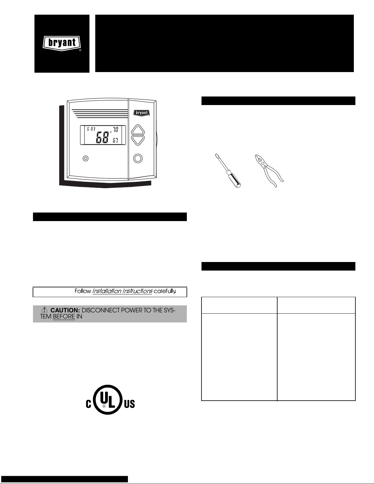
B. Assemble tools:
COOL
HEAT
o
o
Am
:
MULTI-STAGE • SEVEN DAY PROGRAMMABLE
Table of Contents
STEP #1 PREPARATION 1
STEP #2 WIRE CONNECTIONS 1
SAMPLE WIRING DIAGRAMS 2
STEP #3 TEST OPERATION 2
TROUBLESHOOTING 2
CALIBRATION 2
IMPORTANT:
CAUTION: DISCONNECT POWER TO THE SYS-
TEM BEFORE
This device complies with Part 15 of the FCC rules. Operation is subject to the following 2 conditions: (1) This device
may not cause harmful interference, and (2) This device
must accept any interference received, including interference that may cause undesired operation.
Follow
Installation Instructions
INSTALLING THE THERMOSTAT.
carefully.
Flat Blade
Screwdriver
Wire Cutter
and Stripper
C. Carefully unpack the thermostat. Save the screws,
bracket, and instructions.
D. Turn off the power to the system at the main fuse
panel. Most systems have a separate breaker for
disconnecting power to the indoor and outdoor
units.
STEP #2 WIRE CONNECTIONS
Refer to the chart below, or the wiring diagrams that
follow for thermostat functions and corresponding
thermostat connectors.
INSTALL ON THE
FUNCTION
Lo Fan G1
Compressor Y
Heating H2
24 v Power R
Common C
Rev. Valve O*
Hi Fan G2
Remote Sensor +5vdc RS+5
Remote Sensor Signal RS
Remote Sensor Ground RS GND
Dry Contact Switch 1 CK1
Dry Contact Switch 2 CK2
Defrost H1
*Only used with Heat Pump Systems.
NEW THERMOSTAT
CONNECTOR MARKED
LISTED
Page 2
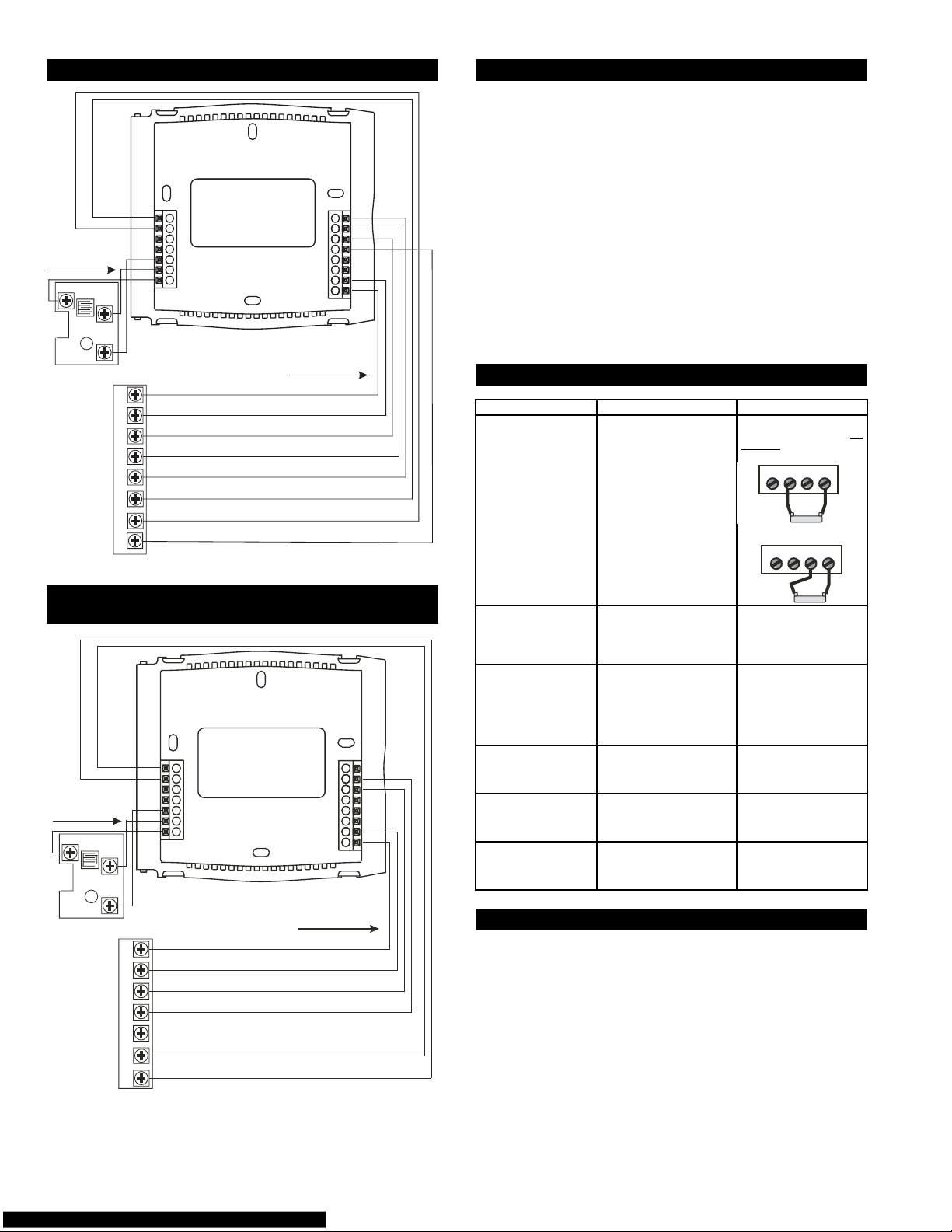
Sample Wiring Diagrams HEAT PUMP
3 conductor 18 ga
unshielded cable from
the thermostat to the
remote sensor.
RS-GND
COMPRESSOR
REVERSING
AUX HEAT
g
RS
RS+V
COMMON
POWER
LO FAN
VALVE
HIGH FAN
DEFROST
H2
e
G1 R CY
OH2
G2
H1
G2
RS+5
RS
RS GND
8 Conductor 18 gage
unshielded cable from the
thermostat to the equipment.
CK1
CK2
G1
H1
O
Y
R
C
STEP #3 TEST OPERATION
Turn the power on to the HVAC (heating, ventilation,
A.
and air conditioning) system.
B.
Press the
MODE
button until the HEAT icon appears
on the display. Press the Up or Down buttons until the
set temperature is 10 degrees above room temperature. The unit should turn on and supply heat.
C.
Press the
MODE
button until the COOL icon appears
on the display. Press the Up or Down buttons until the
set temperature is 10 degrees below room temperature. The unit should turn on.
NOTE: Most equipment has a time delay between cycles. This feature is defeatable on the thermostat.
Consult the Owner's Manual under Setup: Cycles per
hour.
D.
Press the
MODE
button repeatedly until OFF is displayed on the thermostat.
TROUBLESHOOTING
SYMPTOM CAUSE REMEDY
When not using a common wire the air conditioning equipment tries
repeatedly to tur n on,
but cannot. At times
the display dims or disappears.
There is not enough power
available to “power share”.
Connect a 270 ohm,
10 watt power resistor at
the unit as shown below.
For Probl em A/C
RH2 YC
TR300-10w
For Probl em Heat
RH2 Y C
Sample Wiring Diagrams HEAT-COOL/
COOLING ONLY
H2
3 conductor 18 gag
unshielded cable from
the thermostat to the
remote sensor.
RS-GND
COMMON
24vPOWER
COMPRESSOR
AUX HEAT
HIGH FAN
e
RS
RS+V
LO FAN
G1 R CY
OH2
G2
G2
RS+5
RS
RS GND
8 Conductor 18 gage
unshielded cable from the
thermostat to the equipment.
NOTE: For cooling only, the H2 connection is not required.
CK1
CK2
G1
H1
O
Y
R
C
TR300-10w
The air conditioning
does not attempt to
turn on.
The display is blank. Lack of proper power. Make sure power is
The air conditioning
does not attempt to
turn on.
The heating does not
attempttoturnon.
The strip heater turns
off well before reaching
set point.
The compressor timer lockout may prevent the air
conditioner from turning
on, for a period of time.
The cooling set point is set
too high.
The heating set point is set
too low.
Heat pump is incorrectly
selected “on”inthe
Advanced Setup.
Consult the Owner’s
Manual in the Setup section to defeat the cycles
per hour and compressor
timeguard.
turned on to the HVAC
unit and there is 24 vac
between R and H2.
If the HVAC unit is cooling only, check there is
24 vac between R and C.
Press the down arrow
until the cooling set point
is 10 degrees lower than
the room temperature.
Press the up arrow until
the heating set point is
10 degrees higher than
the room temperature.
Select heat pump “off”
during Advanced Setup
programming. Consult
the Owner’s Manual.
CALIBRATION
Every thermostat is calibrated before it leaves the factory. Under normal circumstances there will never be a need to recalibrate the thermostat again. To accommodate s
the thermostat may be recalibrated following these steps:
1. While holding the Mode button in, press the fan button
for 5 seconds. After all the icons in the display appear,
release the buttons.
2. Press the Up and Down arrow buttons simultaneously,
twice.
3. Press the up or down buttons until the flashing number
equals the current room temperature.
4. Press the Mode button to return to normal operation.
pecial needs
,
Copyright 2004 Bryant Heating & Cooling Systems Printed in U.S.A. CATALOG NO. 5353-000
 Loading...