

Bryant 619P Series, 538P Series Installation Instructions Manual
619P/538P
Heating & Cooling Systems
TABLE OF CONTENTS
PARTS LIST
MODEL NU MBER NOMENCLATURE
SAFETY C ONSIDERATI ONS
DIMENS IONS
CLEARA NCES
INSTALLATIO N INSTRUCTION S
INDOOR U NIT INSTAL LATION
OUTDOO R UNIT INSTA LL ATION
RUNNIN G TESTS
PAGE
2
3
4
5
6
7
8
12
17
NOTE: Re ad the entire ins tr uction manual b ef ore starting th e
instal lation.
538/619P
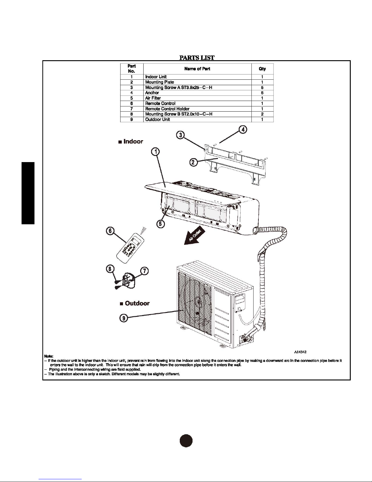
PARTS
Part
No.
1 Indoor Unit
2 Mounting Plate
3 Mounting
4 Anchor 5
Air Filter
5
Remote Control
6
7 Remote Control Holder
6 Mounting
9 Outdoor Unit 1
Saaw A ST3.9x25-C-H
Saew B ST2.0x10-C-H
N•m•
LIST
of
Pert
•Indoor
Qty
5
2
• Outdoor
Nale:
- If the outdoor unit
enters the wall
- Piping and
-
The
illuslnltion
Is
higher than the Indoor unit, prevent
to the indoor unit. This will
the
Interconnecting wlrtng
above
is only a
sketch.
ensure
are
fteld
Dilfarent models
that
BUpplled.
rain
from
ftowtng
Into
the
rain
will drip from the connection pipe before it enters the wall.
may
be
slightly dilfarent
Indoor unit along the connection pipe
2
•
by
making a
downward
arc In the connection pipe
A14342
before
It

40 MA Q B 09 B -- 3
Digits 7, 8 indicate the system's capacity in 1000
BTU/Hr
Example: 09 = 9000 BTU/Hr
Maximum Number of fan coil units connected to the outdoor unit
B = 1:1
Digit 12 indicates voltage
1 = 115/l/60
3 = 208-230-1-60Hz
Digits 10, 11 - blank
Digit 9 - Indoor Fan Coil Unit Type
B = High-Wall
C = Cassette
D = Ducted
F = Console
G = Underceiling
H = High Wall Color Variation
- = Outdoor
Digit 5 indicates the system's type:
C = Cooling only;
Q = Heat pump
Digits 3 and 4 represent the model
The first two digits indicate the equipment type.
40 = Indoor unit;
38 = Outdoor uni
3
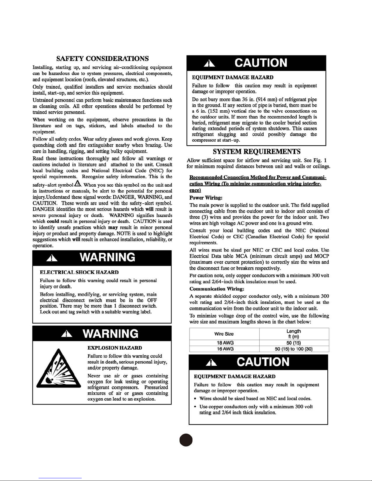
SAFETY CONSIDERATIONS
Installing, starting up, and servicing air-conditioning equipment
to
can be hazardous due
and equipment location (roofs, elevated structures, etc.).
Only trained, qualified installers and service mechanics should
install, start-up, and service this equipment.
Untrained personnel can perform basic maintenance functions such
as
cleaning coils. All other operations should be performed by
trained service personnel.
When working on the equipment, observe precautions in the
literature and on tags, stickers, and labels attached to the
equipment.
Follow all safety codes.
quenching cloth and fire extinguisher nearby when brazing. Use
care in handling, rigging, and setting bulky equipment.
Read these instructions thoroughly and follow all warnings or
cautions included in literature and attached to the unit. Consult
local building codes and National Electrical Code
special requirements. Recognize safety information. This is the
safety-alert
in instructions or manuals, be alert
injury. Understand these signal words: DANGER, WARNING, and
CAUTION. These words are used with the safety-alert symbol.
DANGER identifies the most serious hazards which will result in
severe personal injury or death. WARNING signifies hazards
which could result in personal injury or death. CAUTION is used
to
identify unsafe practices which
injury or product and property damage. NOTE is used
suggestions which will result in enhanced installation, reliability, or
operation.
symbol&.
A.
ELECTRICAL
Failure to follow this warning could result in personal
injury or death.
Before installing, modifying, or servicing system, main
electrical disconnect switch must be in the OFF
position. There may be more than 1 disconnect switch.
Lock out and tag switch with a suitable warning label.
A.
system pressures, electrical components,
Wear
safety glasses and work gloves. Keep
(NEC) for
When you see this symbol on the unit and
to
the potential for personal
may
result in minor personal
to
WARNING
SHOCK
HAZARD
WARNING
EXPLOSION HAZARD
Failure
to
result in death, serious personal injury,
and/or property damage.
Never use air or gases containing
oxygen for leak testing or operating
refrigerant compressors. Pressurized
mixtures
oxygen can lead
follow this warning could
of
air or gases containing
to
an
explosion.
highlight
A.
EQUIPMENT DAMAGE HAZARD
Failure
to
damage or improper operation.
Do not bury more than 36 in. (914 mm)
in the ground.
6 in. (152 mm) vertical rise
a
the outdoor units.
buried, refrigerant may migrate
during extended periods
refrigerant slugging and could possibly damage the
compressor
follow this caution may result in equipment
CAUTION
If
any section
If
more than the recommended length is
of
at
start-up.
of
of
pipe is buried, there must be
to
the valve connections on
to
the cooler buried section
system shutdown. This causes
refrigerant pipe
SYSTEM REQUIREMENTS
Allow sufficient space for airflow and servicing unit. See Fig. 1
for minimum required distances between unit and walls or ceilings.
and
Recommended Connection Method for Power
cation Wiring
ence>
Power Wiring:
The main power is supplied
connecting cable from the outdoor unit
three (3) wires and provides the power for the indoor unit.
wires are high voltage AC power and one is a ground wire.
Consult your local building codes and the NEC (National
Electrical Code) or CEC (Canadian Electrical Code) for special
requirements.
All wires must be sized per NEC or CEC and local codes. Use
Electrical Data table MCA (minimum circuit amps) and MOCP
(maximum over current protection)
the disconnect fuse or breakers respectively.
Per caution note, only copper conductors with a minimum 300 volt
rating and 2/64-inch thick insulation must be used.
Communication Wiring:
A separate shielded copper conductor only, with a minimum 300
volt rating and 2/64-inch thick insulation, must be used
communication wire from the outdoor unit
To
minimize voltage drop
wire size and maximum lengths shown in the chart below:
EQUIPMENT DAMAGE HAZARD
Failure to follow this caution may result in equipment
damage or improper operation.
• Wires should be sized based on NEC and local codes.
• Use copper conductors only with a minimum 300 volt
rating and 2/64 inch thick insulation .
A.
ITo
minimize communication wiring interfer-
to
Wire Size
18AWG
16AWG
the outdoor unit. The field supplied
of
the control wire, use the following
to
indoor unit consists
to
correctly size the wires and
to
50 {15)
CAUTION
Communi-
the indoor unit.
Length
ft (m)
50 {15)
to
100 (30)
as
of
Two
the
4
•
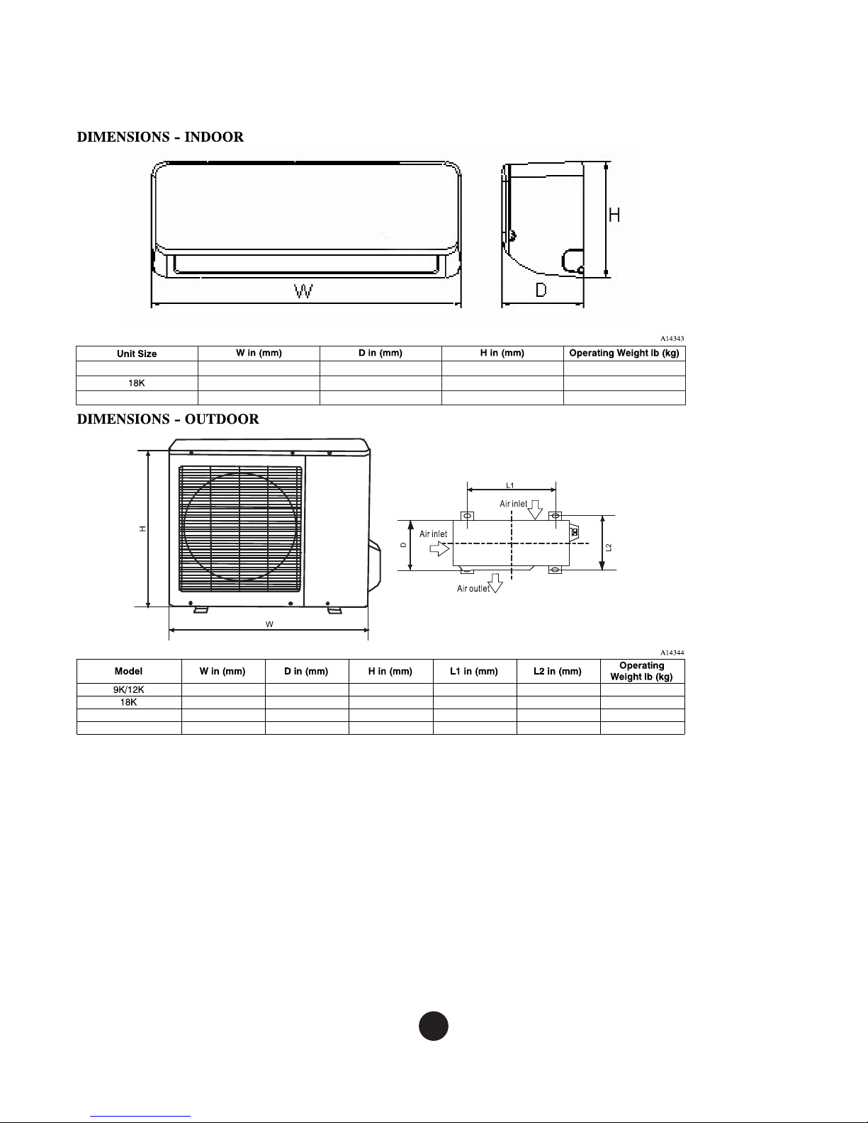
9K/12K
24K/30K
32.9 (835) 7.8 (198) 11.0 (280) 19.2 (8.7)
39.0 (990) 8.6 (218) 12.4 (315) 26.5 (12.0)
46.7 (1186) 10.2 (258) 13.4 (343) 40.8 (18.5)
24K
30K
32.0 (810) 22.0 (558) 82.5 (37.4)
32.3 (845) 27.6 (700) 102.5 (46.5)
37.2 (945) 31.9 (810) 137.6 (62.4)
37.2 (945) 31.9 (810)
12.2 (310)
12.6 (320)
15.6 (395)
15.6 (395) 157.6 (71.5)
20.9 (530)
22.1 (560)
25.1 (640)
25.1 (640)
11.4 (290)
13.2 (335)
15.9 (405)
15.9 (405)
5
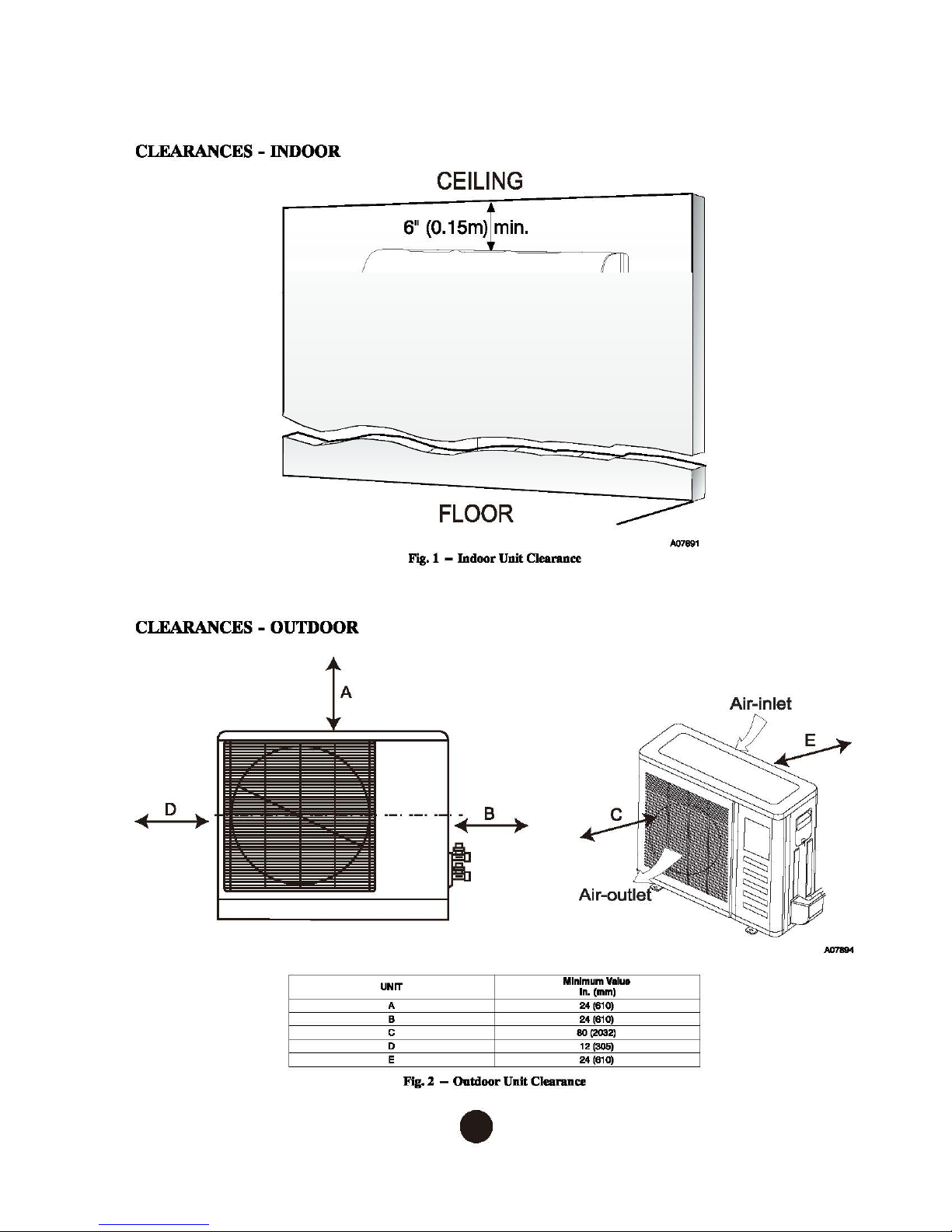
CLEARANCES-ENDOOR
511
(0.13mf
min.
~
,,
CEILING
11
6
(0.15m) min.
s·
.._
---
FLOOR
Fig. 1 -
(1.8m)
Indoor
Unit
00
---
Clearance
I
511
(0.13m)
=
min.
"'--
::::::-
_;n
~---
A07891
CLEARANCES-OUTDOOR
UNIT
A
B
c
D
E
Fig. 2 -
B •
Outdoor
Unit
Minimum V.lua
eo
Clearance
ln.(mm)
24
(810)
24
(810)
(2032)
12
(305)
24
(610)
Air-inlet
6
•
 Loading...