

Bryant 538F, 619F Owner's Manual
538F / 619F
High --Wall Ductless Split S
Sizes 09 to 18
yste
m
Owner' s
NOTE: Read the entire instruction manual before starting the
installation.
Manual
the environmentally sound refrigerant
TABLE OF CONTENTS
PAGE
2SAFETY CONSIDERATIONS . . . . . . . . . . . . . . . . . . . . . . . . .
SYSTEM REQUIREMENTS 2. . . . . . . . . . . . . . . . . . . . . . . . . ..
Wo
rking temperature range 3
Model numbers
Parts name 4. . . . . . . . . . . . . . . . . . . . . .
Remote controller 6. . . . . . . . . . . . . . . . . . . . . . . . . . . . . . . . . . . ..
Lost or damaged remote control 16. . . . . . . . . . . . . . . . . . . . . . . . .
CLEANING AND MAINTENANCE 17.
Troubleshooting 19. . . . . . . . . . . . . . . . . . . . . . . . . . . . . . . . . . . . .
Installation diagram 23. . . . . . . . . . . . . . . . . . . . . . . . . . . . . . . . .
Tools for installation
INDOOR UNIT INSTALLATION 26. . . . . . . . . . . . . . . . . . . . . .
OUTDOOR UNIT INSTALLATION FOR SINGLE ZONE APLICATIONS
(REFER TO THE 538K OWNER'S MANUAL FOR MULTIZONE)
Vacuum pumping
Leakage detection 34. . . . . . . . . . . . . . . . . . . . . . . . . . . . . . . . . . .
Checking installation 35. . . . . . . . . . . . . . . . . . . . . . . . . . . . . . . .
Testing unit operation 35. . . . . . . . . . . . . . . . . . . . . . . . . . . . . . ..
Configuring connection pipe 36. . . . . . . . . . . . . . . . . . . . . . . . . ..
Pipe expanding method 38. . . . . . . . . . . . . . . . . . . . . . . . . . . . . ..
. . . . . . . . . . . . . . . . . . . . . . . . . . . . . . . . . . . . . .
. . . . . . . . . . . . . . . . . . . . . . . . . . . ..
. . . . . . . . . . . . . . . . . . ..
. . . . . . . . . . .
. . . . . . . .
. . . . . . . .
3
5. . . . . . .noitidnoc ria dna etomer gnimmargorp - snoitcurtsnI r e
24. . . . . . . . . . . . . . . . . . . . . . . . . . . . . . . . .
31
34. . . . . . . . . . . . . . . . . . . . . . . . . . . . . . . . . . . .
Please read this Owner’s Information Manual carefully before installing and using this appliance
and keep this manual for future reference.
For your convenience, please record the model and serial numbers of your new equipment in the
spaces provided. This information, along with the installation data and dealer contact information,
will be helpf
UNIT INFORMATION
Model #
Serial #
INSTALLATION INFORMATION
Date Installed
ul should your system require maintenance or service.
NOTE TO EQUIPMENT OWNER:
DEALERSHIP CONTACT INFORMATION
Company Name:
Address:
Phone Number:
Technician Name:
SAFETY CONSIDERATIONS
Installing, starting up, and servicing air--conditioning equipment
can be hazardous due to system pressures, electrical components,
and equipment location (roofs, elevated structures, etc.).
Only trained, qualified installers and service mechanics should
install, start--up, and service this equipment.
Untrained personnel can perform basic maintenance functions such
as cleaning coils. All other operations should be performed by
trained service personnel.
When working on the equipment, observe precautions in the
literature and on tags, stickers, and labels attached to the
equipment.
Follow all safety codes. Wear safety glasses and work gloves. Keep
quenching cloth and fire extinguisher nearby when brazing. Use
care in handling, rigging, and setting bulky equipment.
Read these instructions thoroughly and follow all warnings or
cautions included in literature and attached to the unit. Consult
local building codes and National Electrical Code (NEC) for
special requirements. Recognize safety information. This is the
safety--alert symbol
!
!
. When you see this symbol on the unit and
in instructions or manuals, be alert to the potential for personal
injury.Understand these signal words: DANGER, WARNING, and
CAUTION. These words are used with the safety-- alert symbol.
DANGER identifies the most serious h azards which will result in
severe personal injury or death. WARNING signifies hazards
which could result in personal injury or death. CAUTION is used
to identify unsafe practices which may result in minor personal
injury or product and property damage. NOTE is used to highlight
suggestions which will result in enhanced installation, reliability, or
operation.
!
WARNING
ELECTRICAL SHOCK HAZARD
Failure to follow this warning could result in personal
injury or death.
Before installing, modifying, or servicing system, main
electrical disconnect switch must be in the OFF
position. There may be more than 1 disconnect switch.
Lock out and tag switch with a suitable warning label.
EXPLOSION HAZARD
Failure to follow this warning could
result in death, serious personal injury,
and/or property damage.
Never use air or gases containing
oxygen for leak testing or operating
refrigerant compressors. Pressurized
mixtures of air or gases containing
oxygen can lead to an explosion.
!
WARNING
CAUTION
!
EQUIPMENT DAMAGE HAZARD
Failure to follow this caution may result in equipment
damage or improper operation.
Do not bury more than 36 in. (914 mm) of refrigerant pipe
in the ground. If any section of pipe is buried, there must be
a 6 in. (152 mm) vertical rise to the valve connections on
the outdoor units. If more than the recommended length is
buried, refrigerant may migrate to the cooler buried section
during extended periods of system shutdown. This causes
refrigerant slugging and could possibly damage the
compressor at start--up.
SYSTEM REQUIREMENTS
Allow sufficient space for airflow and servicing unit. See Fig. 1
for minimum required distances between unit and walls or
ceilings.
Recommended Connection Method for Power and
Communi-
cation Wiring (To minimize communication wiring
interfer-
ence)
Power Wiring:
The main power is supplied to the outdoor unit. The field supplied
connecting cable from the outdoor unit to indoor unit consists of
three (3) wires and provides the power for the indoor unit. Two
wires are high voltage AC power and one is a ground wire.
Consult your local building codes and the NEC (National
Electrical Code) or CEC (Canadian Electrical Code) for special
requirements.
All wires must be sized per NEC or CEC and local codes. Use
Electrical Data table MCA (minimum circuit amps) and MOCP
(maximum over current protection) to correctly size the wires and
the disconnect fuse or breakers respectively.
Per caution note, only copper conductors with a minimum 300 volt
rating and 2/64--inch thick insulation must be used.
Communication Wiring:
A separate shielded copper conductor only, with a minimum 300
volt rating and 2/64--inch thick insulation, must be used as the
communication wire from the outdoor unit to the indoor unit.
To minimize voltage drop of the control wire, use the following
wire size and maximum lengths shown in the chart below:
Wire Size
Length
ft (m)
18 AWG 50 (15)
16 AWG 50 (15) to 100 (30)
CAUTION
!
EQUIPMENT DAMAGE HAZARD
Failure to follow this caution may result in equipment
damage or improper operation.
S Wires should be sized based on NEC and local codes.
S Use copper conductors only with a minimum 300 volt
rating and 2/64 inch thick insulation.
-2-
Working temperature range
Indoor side DB/WB
( )
°F/°C
(°F/°C)
Outdoor side DB/WB
Maximum cooling
115/75(46.1/23.9)
Maximum heating
80/-(26.7/-)
75/64.9(23.9/18.3)
The operating temperature range (outdoor temperature) for cooling only unit is
-0.4°F(-18°C) (-30°C)~114.8°F(46°C); for heat pump unit is -22°F ~ 72.5°F(24°C)
NOTICE:
-3-
System
Tons
System
Btuh
Volt-Ph@
60Hz
Indoor Model Number
Indoor Unit
Color
Outdoor Model Number
Single Zone
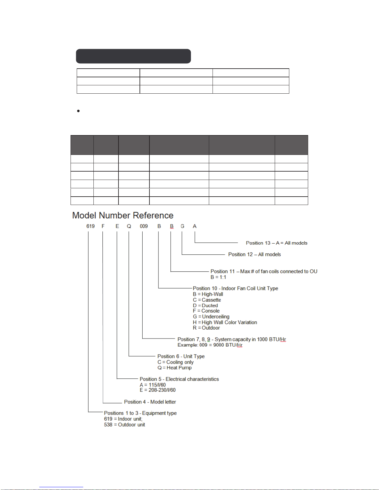
0.75 9,000 208/230-1 619FEQ009BBGA 538FEQ009RBGA Gray
1 12,000 208/230-1 619FEQ012BBGA 538FEQ012RBGA Gray
1.5 18,000 208/230-1 619FEQ018BBGA 538FEQ018RBGA Gray
1.5 12,000 208/230-1 619FEQ018HBGA 538FEQ018RBGA White
0.75 9,000 208/230-1 619FEQ009HBGA 538FEQ009RBGA White
1 12,000 208/230-1 619FEQ012HBGA 538FEQ012RBGA White
Model Number
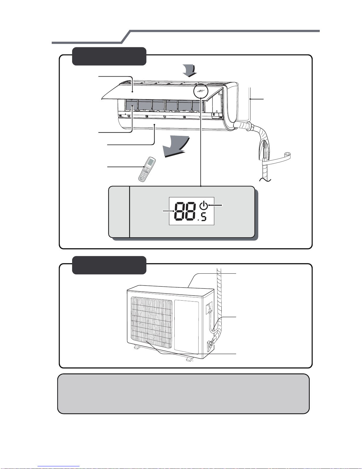
Parts name
-4-
Indoor Unit
panel
filter
horizontal louver
remote controller
display
air inlet
power wire
air outlet
power
tem.display
Outdoor Unit
air inlet
Connection wire
air outlet
NOTE:
The illustration above is only a sketch. Different models may be slightly
different.
Instructions - programming remote and air conditioner
-5-
The RF remote control must be synchronized with air conditioner prior to use.
Follow the instructions below.
Note
Synch remote controls within 6.5ft (2m) from air conditioning unit.
While synching, the remote controller and air conditioner should be on standby
status.
Synching remote controller with air conditioner is a one-time requirement.
Programming remote control
. Press standy status on air conditioner.
. Stand near air conditioner while holding remote control. Press standby button on remote.
. Synching will occur automatically.
. If synch does not occur, move closer to unit and repeat steps.
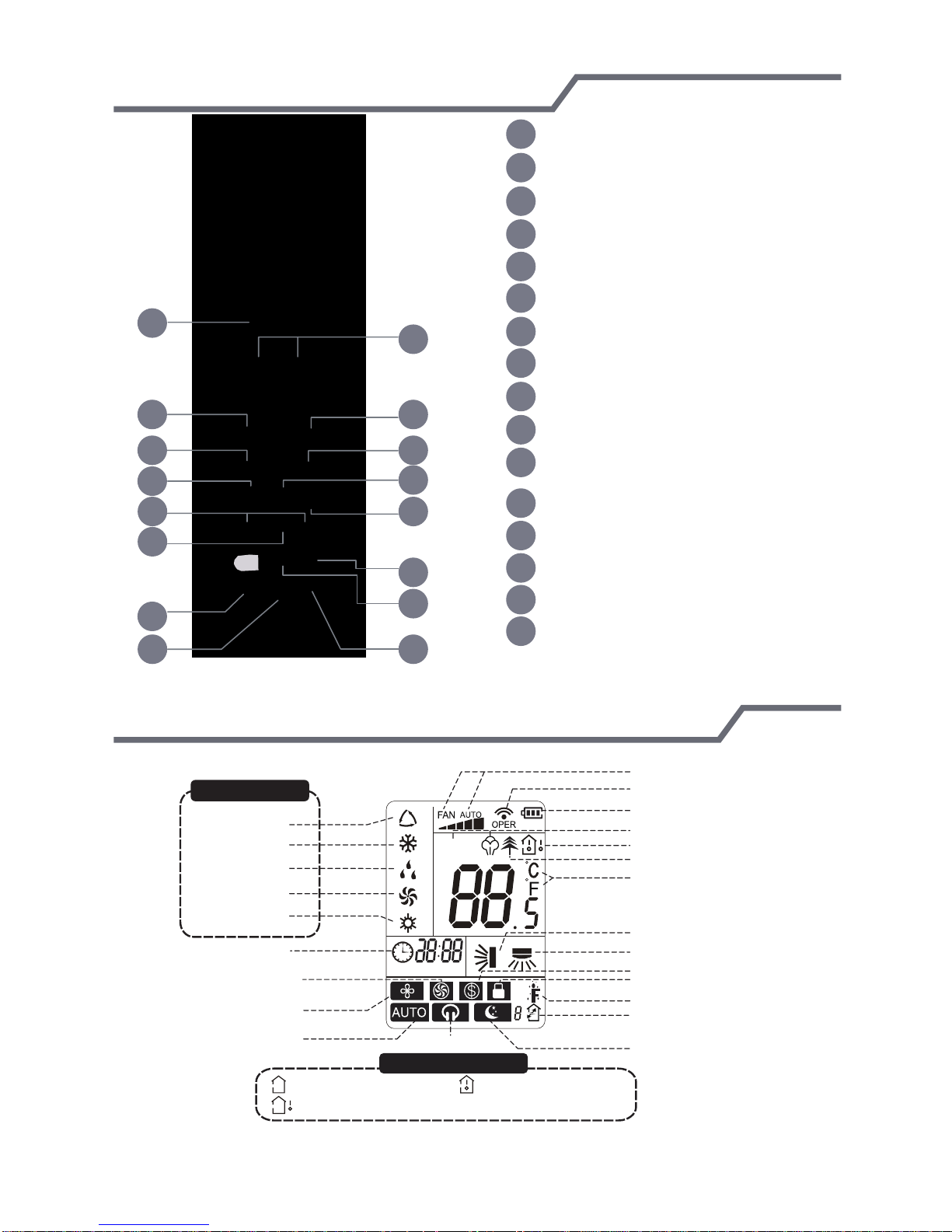
Remote controller
-6-
1
3
7
10
11
2
4
65
8
9
12
1 ON/OFF button
+/- button
2
Cool button
3
Heat button
4
Fan button
5
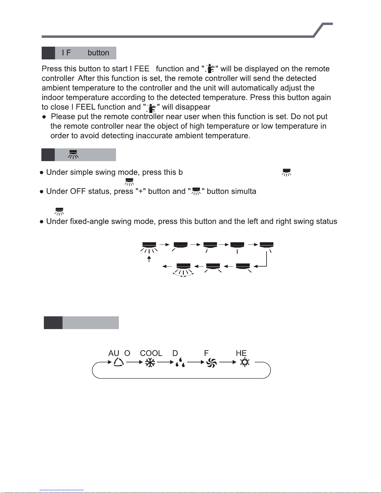
6 I FEEL button
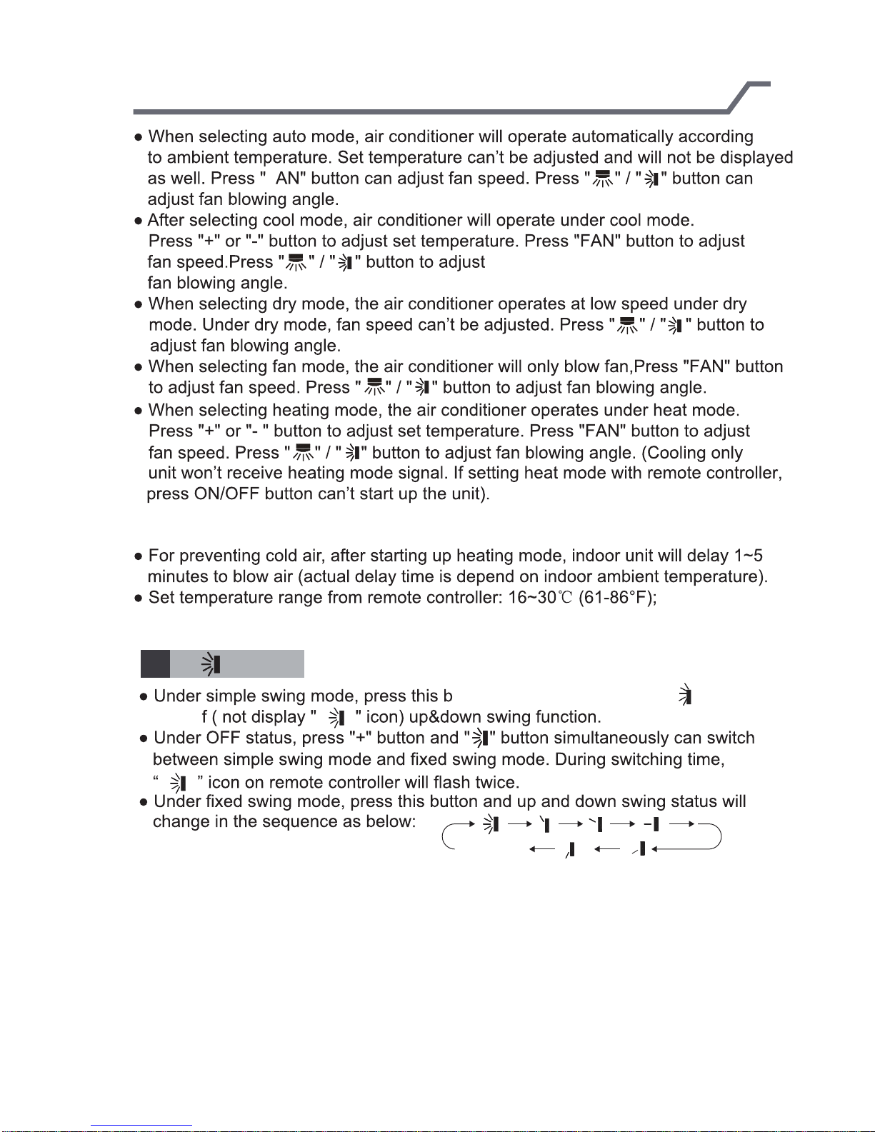
up down swing button
7
8
Mode button
9
Left right swing button
10
T-ON/T-OFF button
11
Clock button
12
X-fan button
13
Air button
14
Light button
15
13
Sleep button
14
16
15
16
WIFI button
Introduction for icons on display screen
Set fan speed
Operation mode
Auto mode
Cool mode
Dry mode
Fan mode
Heat mode
Set time
Turbo fan speed
X-FAN function
Auto quiet mode
INTELLIGENT
HOUR ON OFF
Quiet mode
Temp. display type
:Set temp.
:Outdoor ambient temp.
WIFI
:Indoor ambient temp.
Send signal
battery power
humidity functions
Temp.display type
Healthy mode
Set temperature
Up & down swing
Left & right swing
46°F (8°C) heating function
child lock
I feel function
Replacing air
Sleep mode
Matching Remote Control
-7-
The RF remote control must be synchronized with air conditioner prior to use.
Follow the instructions below.
Note
Synch remote controls within 6.5ft (2m) from air conditioning unit.
While synching, the remote controller and air conditioner should be on standby
status.
Synching remote controller with air conditioner is a one-time requirement.
Programming remote control
. Press standy status on air conditioner.
. Stand near air conditioner while holding remote control. Press standby button on remote.
. Synching will occur automatically.
. If synch does not occur, move closer to unit and repeat steps.
REMOTE CONTROL FUNCTIONS
-8-
Note:
After the air conditioner has been properly installed, you can use the remote
control to operate the air conditioner. Press the power button on the remote
control. The green indicator light will display on the air conditioner unit.
Follow the instructions for using the remote control.
1
Use the ON/OFF remote button to turn on or turn off the air conditioner.
The button on the remote will display ON when the air conditioner is on.
2
The +/- button increases or decreases the temperature setting on the air
conditioning unit. Hold the "+" or "-" for 2s to change the temperature setting.
NOTE: Temperature setting can not be adjusted in "auto mode".
Press the "+" or "-" for setting and adjusting TIMER.
3
Press the Cool button to operate in cool mode.
4
Press the Heat button to operate in heat mode.
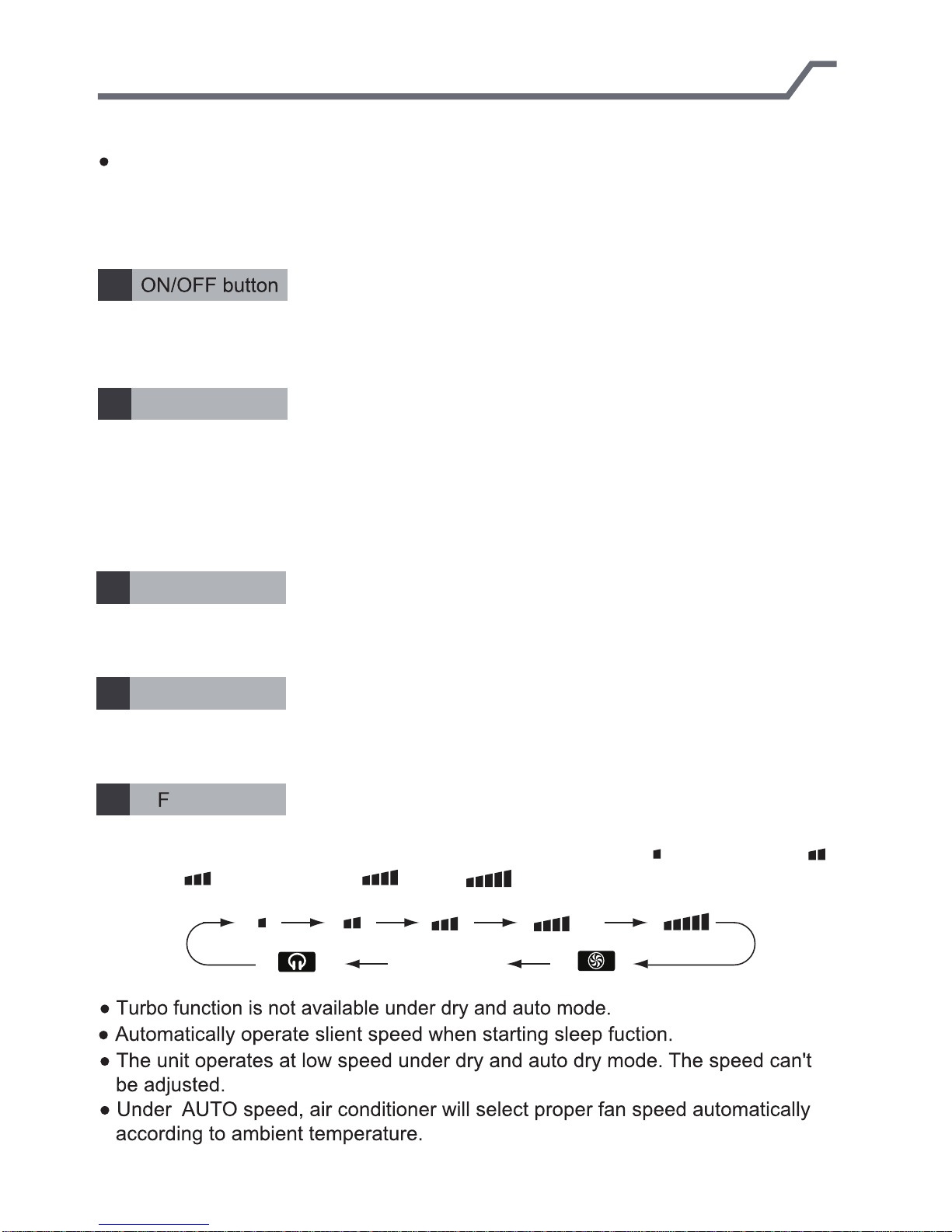
5
Press the FAN button to adjust the fan circulation speed: low( ), low medium( ),
medium( ), medium high( ), high( ), super, auto and quiet.
+/- button
Cool button
Heat button
AN button
Note:
Auto
REMOTE CONTROL FUNCTIONS
-9-
6
7
turn off ( not display " " icon) left&right swing function.
between simple swing mode and fixed swing mode. During switching time,
“ ” icon on remote controller will flash twice.
will change in the sequence as below:
EEL
L
.
.
button
utton can turn on (display " " icon ) or
neously can switch
no display
(stops at current position)
MODE button
8
Press this button to select your required operation mode.
T ANRY AT
REMOTE CONTROL FUNCTIONS
-10-
F
Note:
9
turn of
button
utton can turn on ( display " " icon) or
no display
(horizontal louvers stops
at current position)
REMOTE CONTROL FUNCTIONS
-11-
10
“T-ON” button can set the time for timer on. After pressing this button, " " icon
disappears and the word “ON" on remote controller blinks. Press “+” or “-”button
to adjust T-ON setting. After each pressing “+” or “-”button, T-ON setting will
increase or decrease 1min. Hold “+” or “-”button, 2s later, the time will change
condition that T-ON is started up, press “T-ON” button to cancel it.
“T-OFF” button can set the time for timer off. After pressing this button, " " icon
disappears and the word "OFF" on remote controller blinks. Press "+" or "-" button
to adjust T-OFF setting. After each pressing "+" or "-" button, T-OFF setting
will increase or decrease 1min. Hold "+" or "-" button, 2s later, the time will change
"OFF" will stop blinking. " " icon resumes displaying. Cancel T-OFF.Under the
condition that T-OFF is started up, press “T-OFF” button to cancel it.
T-ON/T-OFF button
T-ON button
quickly until reaching your required time. Press“T-ON”to confirm it. The word “ON”
will stop blinking. " " icon resumes displaying.Cancel TIMER ON: Under the
T-OFF button
until reaching your required time. Press“T-OFF”to confirm it. The word “ON”will
Note:
ff status, you can set T-OFF or T-ON simultaneously.
T-ON or T-OFF, please adjust the clock time.
After starting up T-ON or T-OFF, set the constant circulating valid. After that,
air conditioner will be turned on or turned off according to setting time. ON/OFF
button has no effect on setting. If you don’t need this function, please use remote
controller to cancel it.
11
Press this button to set clock time. " " icon on remote controller will blink.
Press "+" or "-" button within 5s to set clock time. Each pressing of "+" or "-"
button, clock time will increase or decrease 1 minute. Hold "+" or "-" button, 2s
later, time will change quickly. Release this button when reaching your required
time. Press “CLOCK”button to confirm the time. " " icon stops blinking.
Note:
CLOCK button
The interval between two operations can’t exceeds 5s. Otherwise, remote
controller will quit setting status. Operation for TIMER ON/TIMER OFF is
the same.
REMOTE CONTROL FUNCTIONS
-12-
12
Pressing this button in COOL or DRY mode, the icon " " is displayed and the
indoor fan will continue operation for 2 minutes in order to dry the indoor unit even
though you have turned off the unit. After energization, X-FAN OFF is defaulted.
X-FAN is not available inAUTO, FAN or HEAT mode.
This function indicates that moisture on evaporator of indoor unit will be blowed
after the unit is stopped to avoid mould.
button indoor fan will continue running for about 2 min. at low speed. In this
period, press X-FAN button to stop indoor fan directly.
button, the complete unit will be off directly.
Press this button to select your required operation mode.
Note:there is no this function for this unit. If press this button,the main unit will click,
X-FAN button
FAN function on: After turning off the unit by pressing ON/OFF
FAN function off: After turning off the unit by pressing ON/OFF
13
Air button
but it also runs under original status.
cancel
LIGHT button
14
Pressing this button to turn off display light on indoor unit. Press this button again
to turn on display light.
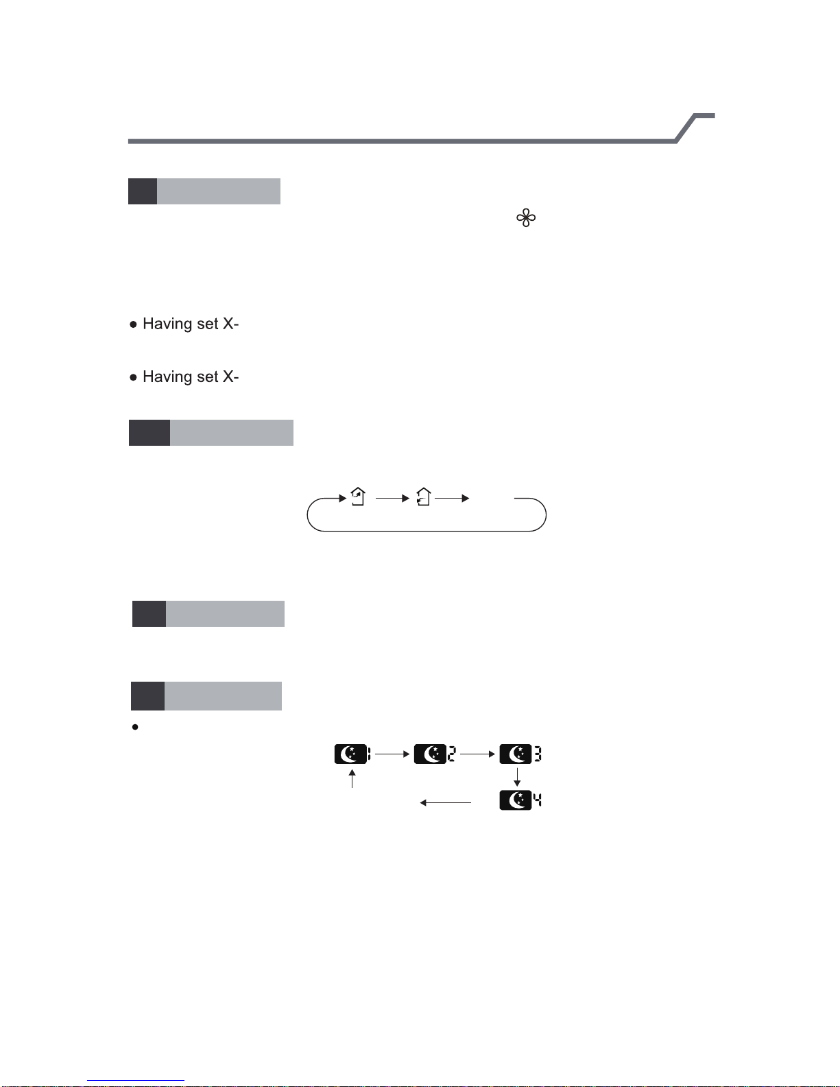
15
SLEEP button
Pressing this button can select Sleep 1, Sleep 2,Sleep 3, Sleep 4 or cancel Sleep
circularly as below:
cancel
 Loading...