

Page 1
Bryant
JiiTJpüA
Airconditioning
Indianapolis, IN
City of Industry. CA
HORIZONTAL RIGHT
FAN-COIL UNITS
fi l e
CO P Y
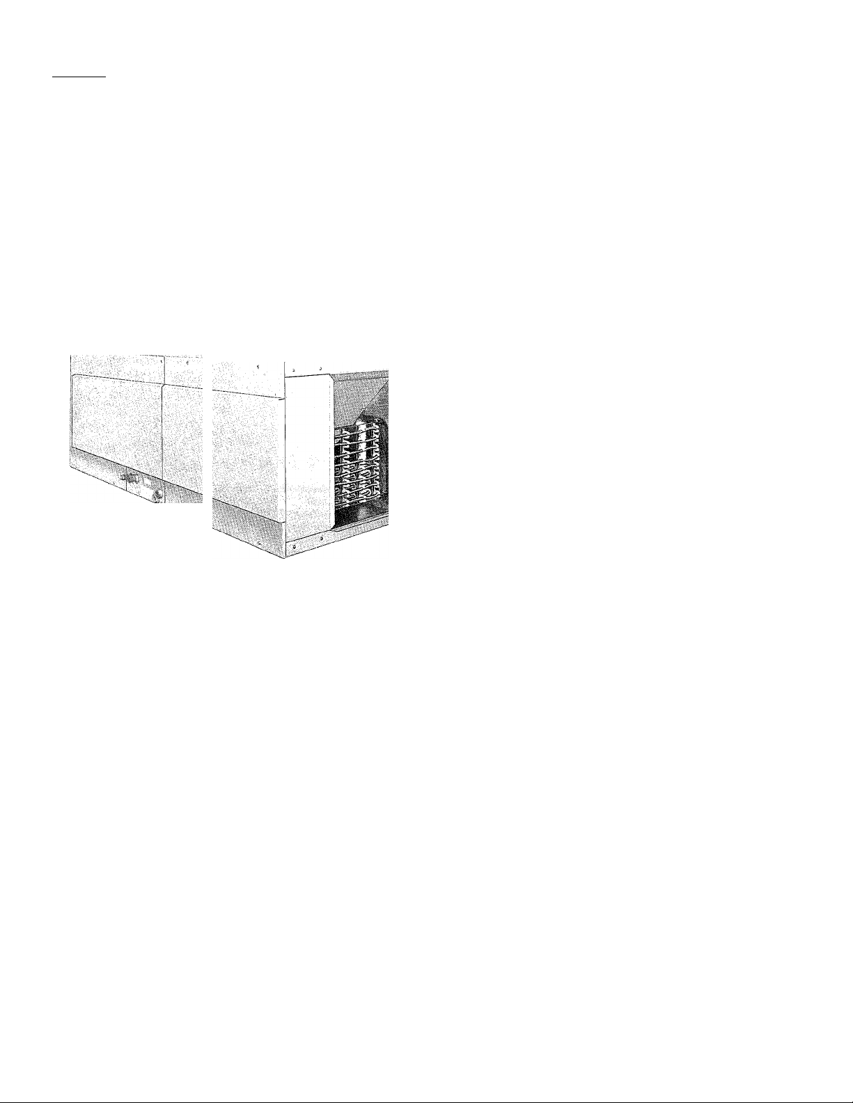
Model 517G Fan-Coil Units are packaged air handlers that are
specifically designed for horizontal right-hand discharge for
split-system applications—both conventional air conditioning and
heat pump.
These fan-coil units are available In nominal coil sizes 042, 048,
and 060. Fan-Coil units with electric heaters and the accessory
heat packages for field-installation into the fan-coil units without
heaters are available in sizes ranging from 7.5 to 30KW.
Model 517G
Sizes 042, 048,
&060
FEATURES
WRAPAROUND FULLY INSULATED CABINET—One-piece
heavy-duty steel construction helps eliminate casing noise. Fully
insulated interior provides both thermal and acoustic isolation.
The cabinet exterior is finished with an attractive silver sage
enamel.
SPECIAL DESIGN FEATURES—Designed for horizontal-right
mounting attitude. Refrigerant and condensate connections are
provided on the front of the fan-coil units for ease of installation.
Knockouts are provided for optional horizontal suspension,
using suspension rods. Separate access panels for the coil sec
tion and blower/control section on the cabinet front make these
units totally serviceable from the front. A third front access panel
provides easy access to the permanent-type air filter furnished
with each unit.
DIRECT-DRIVE MULTISPEED, PSC, BLOWER MOTORS have
been carefully selected to minimize energy consumption while
providing the airflow to meet the requirements of a wide variety
of applications. A blower speed-tap-changer simplifies speed
changes. Blower and motor assembly is resiliently mounted to
minimize vibration, and slides out for easy servicing.
COMPUTER-DESIGNED INDOOR COILS provide for optimum
heat transfer and cooling and/or heat pump heating efficiency.
Flare refrigerant connections enable quick leak-proof connec
tions, using our precharged refrigerant tubing sets. All coils have
a condensate drain pan with primary and secondary connec
tions, and a holding charge of R-22 refrigerant.
CHECK-FLO-RATER—All coils have a Check-Flo-Rater for effi
cient and dependable refrigerant metering, and to eliminate the
potential service requirements of other metering devices.
Located external to the unit, the Check-Flo-Rater is readily
accessible for piston changeout or maintenance. For added sys
tem reliability, all coils have a liquid-tube strainer to help maintain
clean, unrestricted operation.
ELECTRIC HEAT PACKAGES are available either as factoryinstalled in the heating/cooling fan-coil units or as a field-instalied
accessory for the fan-coil units. The application flexibility of
these heaters is increased with the availability of single- and
three-phase power supply options. The 10-, 15-, and 20-KW
single-phase heaters are available with or without circuit break
ers for internal circuit protection. Sequencer control is used for
incremental energizing and deenergizing of the heater elements.
Field-installation of a heater into a unit has been made extremely
easy—simply slide in the heater, secure with three screws, and
plug-in three leads for blower motor control.
Form No. PDS517G.42.1B
Page 2
¿OD FLARE--------3 LIQUID CONN
Vi
'32^
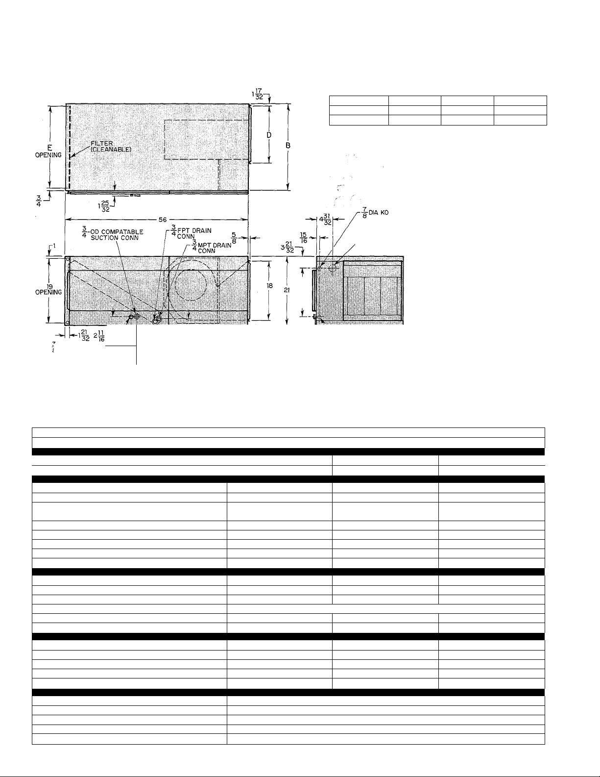
DIMENSIONAL DRAWING
517G Size B
042 22-3/4
048 & 060 26-7/16
(FIELD POWER-COOL)
^2 DIA KO
/ (FIELD POWER-HEAT)
I-Di A KO
S LOW-VOLTAGE
517G DIMENSIONS (Inches)
D E
13-13/16 21
17-9/32 24-1/2
Shipping Weights (lbs)
042
.......................................
048 .........................................185*
060 ........................................
*Add heater weights shown in
heater table to determine ap
proximate weights of fan-coil
units with heaters.
REQUIRED CLEARANCES
Recommended service clearance from front
of unit..........................................................21
Minimum clearance from combustible
materials:
Unit............................................................... 0
First 36 inches of uninsulated supply duct
A33202
when using heater
(Inches)
................................
175*
190*
36
SPECIFICATIONS—UNITS WITHOUT ELECTRIC HEATER
MODEL
SIZE
N042
I N048 1 N060
RATINGS & PERFORMANCE
Nominal Capacity (Btuh)*
Nominal Airflow (FWMin)t
42,000 48,000 60,000
1400
ELECTRICAL
Unit Voits—Phase (60 Hz)
Operating Voltage Range
208/230-1 208/230-1
187-253
Single-Circuit Operation
Rated Load Amps
Minimum Ampacity for Wire Sizing
Minimum Wire Size
Maximum Wire Length (Ft)
Maximum Fuse Size (Amps)
3.8
7.0
14
191/212
15
Control Transformer—24V (VA)
INDOOR COIL
Rows & Fins Per Inch
Height X Width (In.)
Face Area (Sq Ft)
R-22 Refrigerant Metering Device
•Piston ID Number
Condensate Drain Connection (Pri-Sec)
r Check-Flo-Rater |
3&13
32.5x19.4
4.4 5.1 5.1
76
3/4 MPT-3/4 FPT
INDOOR BLOWER & MOTOR
Wheel Diameter x Width (in.)
Filter Size—Cleanable (in.)
Blower Motor HP
Blower Motor Speeds & Type
Rated Load Amps
10x9
20x21 x1
1/2
3 & DD(PSC)
3.8 4.8 5.6
OPTIONAL EQUIPMENT (P/N’S)
Liquid-Tube Swivel Ell (3/8)tt
Vapor-Tube Swivel Ell (3/4)tt
Single-Circuit Kit** 301820-4001
Electric Heat Package***
See Accessory Electric Heat Package Table
Control Package***
See notes on next page.
517G
1600 2000
187-253
4.8
7.0
14
152/158
15
***
3&13
32.5 X 22.8
82
3/4 MPT-3/4 FPT
10x9
20 X 25 x 1
1/2
3 & DD(PSC)
P651-1066
P651-1068
305971-464
208/230-1
187-253
5.6
7.0
14
130/144
15
4&14
32.5 X 22.8
93
3/4 MPT-3/4 FPT
11x9
20 X 25 X1
3/4 ■
3 & DD(PSC)
SSC-66
Page 3
SPECIFICATIONS—UNITS WITH ELECTRIC HEATER
MODEL
SIZE N042075 N042010 P042010 N042012
RATINGS & PERFORMANCE
Nominal Capacity (Btuh)^
Nominal Airflow (FP /Min)t
Electric Heating Output (KW)t
Electric Heating Capacity (MBtuh)t
42,000 42,000 42,000 42,000
1400 1400 1400 1400 1400 1400 1400 1400
7.5 10.0 10.0 12.0 15.0 15.0 18.0 20.0
19.2/23.5 25.6/31.3 25.6/31.3 30.8/37.6 38.5/47.0 38.5/47.0 46.1/56.4 51.3/62.7
ELECTRICAL
Unit Volts—Phase (60 Hz)
Operating Voltage Range
208/230-1
187-253 187-253 187-253
Internal Circuit Protections^ None
208/230-1 208/230-3 208/230-1 208/230-1
187-253 187-253 187-253 187-253 187-253
None iCBft
None
Fuses Fuses
Single-Circuit Operation
Rated Load Amps
Minimum Ampacity for Wire Sizing 40.8/44.5
30.8/33.8 39.8/43.8 24.6/26.8
52/57 33/35.75
Minimum Wire SizeH 8/8 6/6 8/8
Maximum Wire Length (Ft)B 95/96 115/115 146/148
Maximum Fuse Size (Amps)
45/45 60/60 35/40
47.2/51.8 57.8/63.8
61.25/67 74.5/82
6/4
97/154 79/125
70/70 80/90
Dual-Circuit Operation
Rated Load Amps LI & L2
L3&L4
—
32.7/35.8
—
14.5/16
Minimum Ampacity for Wire Sizing
LI &L2
L3&L4
Minimum Wire SizeH LI & L2
L3&L4
Maximum Wire Length (Ft)H L1 & L2
L3&L4
Maximum Fuse Size (Amps) LI & L2
L3&L4
— —
—
_
_
—
_
— —
_ _
— —
—
— —
—
43.1/47 52/57
18/20
8/6
12/12 10/10
89/141 115/115
80/80
45/50 60/60
20/20 25/25
Control Transformer—24V (VA) 60 60 60 60
INDOOR COIL
Rows & Fins Per Inch
Height X Width (In.)
Face Area (Sg Ft)
R-22 Refrigerant Metering Device
Piston ID Number
Condensate Drain Connection (Pri-Sec)
INDOOR BLOWER & MOTOR
Wheel Diameter x Width (In.)
Filter Size—Cleanable (In.)
Blower Motor HP
Blower Motor Speeds & Type
Rated Load Amps
OPTIONAL EQUIPMENT (P/N’S)
Liguid-Tube Swivel Ell (3/8)TT
Vapor-Tube Swivel Ell (3/4)tt
Single-Circuit Kit^*
*See condensing unit or heat pump outdoor section PDS for cooling and/or heating capacity ratings with 517G Fan Coils.
tSee air delivery table in this PDS.
JKW values shown are nominal rated heater outputs at 240V and do not Include blower motor heat. Capacity values shown are calculated using KW
outputs at 208V/230V.
♦♦Single-phase 10-, 15-, or 20-KW electric heaters have the internal circuit protection options shown. Single-phase 12-, 15-, or 20-KW heaters are
wired for dual-circuit operation. The optionai single-circuit kit may be field-installed In units with a 12-, 15-, or 20-KW single-phase fused heater for
single-circuit operation.
ttCB = circuit breakers
ttUsed for right-angle refrigerant connections to the coil.
♦♦♦A 60-VA control transformer for units without factory-supplied heaters is supplied with the accessory electric heat package or control package. The
control package must be field-installed when a heater is not being used.
HWire sizes and lengths are based on copper conductor at 86 ° F (30 ° C) ambient temperature and ampacity shown in table. Insulation must be 90 ° C
on conductor used between the disconnect switch and the heater and at least 75 °C on the conductor used between the disconnect and the serv
ice panel. If other than copper conductor Is used, or if ambient temperature is above 86 ° F, determine wire size from ampacity shown and the Na
tional Electrical Code. Wire lengths shown are measured one way along the wire path between the disconnect and service panel for minimum 2%
voltage drop.
5170
N042015 P042015 P042018
42,000
42,000 42,000 42,000
208/230-3
CBtr
6/4
39.8/43.8
18/20
None
_
35.0/38.5 41.4/45.4
—
46/50.4
_
— 160/161
— 50/60 60/60 100/110 —
6/6 6/6 3/2
_ _
_
_
22.5/25
6/6
102/102
60
3&13
32.5x19.4
4.4
Check-Flo-Rater
76
3/4 MPT-3/4 FPT
10x9
20 X 21 X1
1/2
3 & DD(PSC)
3.8
P651-1066
P651-1068
—
— — 6/6
—
—
—
—
60 60
- 1 - 1 - 1 301820-4001 1 - 1 - 1 301820-4001
N042020
208/230-3 208/230-1
None Fuses
75.8/83.8
54/59 97/107
136/137
120/152 —
39.8/43.8
-
_
—
—
—
—
—
—
36/40
52/57
45/50
8/6
115/115
81/126
60/60
45/50
60
CBtt
_
—
—
CERTIFICATION APPLIES ONLY WHEN
USED WITH PROPER COMPONENTS
AS USTED WITH ARI
SSC-67
Page 4

SPECIFICATIONS—UNITS WITH ELECTRIC HEATER
MODEL
SIZE
1 RATINGS & PERFORMANCE
Nominal Capacity (Btuh)»
Nominal Airflow (Fts/Min)t 1600
Electric Heating Output (KW)t
Electric Heating Capacity (MBtuh)t
1 ELECTRICAL
Unit Voits—Phase (60 Hz)
Operating Voltage Range
Internal Circuit Protection»»
N048075 IN048010
48,000
48,000
1600
7.5 10.0
19.2/23.5
25.6/31.3
208/230-1 208/230-1
187-253 187-253
None
None 1 CBtt
P048010 N048012 N048015 P048015 P048018
48,000 48,000
1600 1600 1600 1600 1600
10.0 12.0
25.6/31.3
208/230-3 208/230-1 208/230-1
187-253
None Fuses
Single-Circuit Operation
Rated Load Amps
Minimum Ampacity for Wire Sizing
Minimum Wire Size»»»
Maximum Wire Length (Ft)»»»
Maximum Fuse Size (Amps)
31.8/34.8
40.8/44.5
8/8
92/93
45/45
40.8/44.8
52/57
6/6
112/113
60/60
25.6/27.6 48.2/52.8
33/35.75 61.25/67
8/8 6/4
140/144 95/151 78/123
35/40 70/70
Dual-Circuit Operation
Rated Load Amps LI & L2
L3&L4
—
— —
Minimum Ampacity for Wire Sizing
LI &L2
Minimum Wire Size»»» LI. & L2
L3 & L4
L3&L4 - -
Maximum Wire Length (Ft)»»» LI & L2
L3&L4
Maximum Fuse Size (Amps) LI & L2 —
L3&L4
Control Transformer—24V (VA)
— —
—
—
—
— — —
—
— —
—
60 60
-
—
—
_
—
60 60
INDOOR COIL
Rows & Fins Per Inch
Height X Width (In.)
Face Area (Sg Ft)
R-22 Refrigerant Metering Device
Piston ID Number
Condensate Drain Connection (Pri-Sec)
INDOOR BLOWER & MOTOR
Wheel Diameter x Width (In.)
Filter Size—Cleanable (In.)
Blower Motor HP
Blower Motor Speeds & Type
Rated Load Amps
OPTIONAL EQUIPMENT (P/N’S)
Liguid-Tube Swivel Ell (3/8)tt
Vapor-Tube Swivel Ell (3/4)tt
Single-Circuit Kit»»
1 1 i 301820-4001 \ = 1
»See condensing unit or heat pump outdoor section PDS for cooiing and/or heating capaoity ratings with 517G Fan Coils.
fSee air delivery table in this PDS.
tKW values shown are nominal rated heater outputs at 240V and do not include blower motor heat. Capacity values shown are calculated using KW
outputs at 208V/230V.
»»Single-phase 10-, 15-, or 20-KW electric heaters have the internal circuit protection options shown. Single-phase 12-, 15-, or 20-KW heaters are
wired for dual-oirouit operation. The optional single-circuit kit may be field-installed in units with a 12-, 15-, or 20-KW single-phase fused heater for
single-circuit operation.
ttCB = circuit breakers.
ttUsed for right-angle refrigerant connections to the coil.
»»»Wire sizes and lengths are based on copper conductor at 86 ° F (30 ° C) ambient temperature and ampacity shown in table. Insulation must be 90 ° C
on conductor used between the disconnect switch and the heater and at least 75 “ C on the conductor used between the disconnect and the serv
ice panel. If other than copper oonductor is used, or is ambient temperature is above 86 °F, determine wire size from ampacity shown and the Na
tional Electrical Code. Wire lengths shown are measured one way along the wire path between the disoonnect and service panel for minimum 2%
voltage drop.
517G
48,000
15.0
30.8/37.6
38.5/47.0 38.5/47.0 46.1/56.4
187-253 187-253
Fuses
58.8/64.8
74.5/82
6/4
80/90
33.7/36.8 40.8/44.8
14.5/16
18/20
43.1/47 52/57
18/20
22.5/25
8/6 6/6
12/12 10/10
87/137
112/113
80/80 102/102
45/50
20/20
60/60
25/25
60 60 60
3&13
32.5x22.8
5.1
Check-Flo-Rater
82
3/4 MPT-3/4 FPT
10x9
20 X 25 X1
1/2
3 & DD(PSC)
4.8
P651-1066
P651-1068
48,000 , -48,000
15.0 18.0
208/230-3 208/230-3
187-253 187-253
CBtt
None None
36.0/39.5 42.4/46.4
46/50.4
_
—
156/157 132/134
—
50/60 60/60
6/6 6/6
54/59
—
— —
— —
_
—
— —
■ —
—
—
SSC-68
Page 5

SPECIFICATIONS—UNITS WITH ELECTRIC HEATER
I
MODEL
SIZE
1 RATINGS & PERFORMANCE
Nominal Capacity (Btuh)*
Nominal Airflow (FF/Min)t 1600 1600 1600
Electric Heating Output (KW)t 20.0 25.0 30.0
Electric Heating Capacity (MBtuh)f: 51.3/62.7 64.1/78.4
1 ELECTRICAL ^
Unit Volts-Phase (60 Hz) 208/230-1 208/230-3 1 208/230-1 ■ 208/230-3 1 208/230-1B 208/230-1 208/230-1
Operating Voltage Range
Internal Circuit Protection** Fuses
Single-Circuit Operation
Rated Load Amps 76.8/84.8
Minimum Ampacity for Wire Sizing 97/107
Minimum Wire Size*** 3/2
Maximum Wire Length (Ft)*** 119/151 — 156/157 154/194 167/168
Maximum Fuse Size (Amps) 100/110
Dual-Circuit Operation
Rated Load Amps L1 & L2
Minimum Ampacity for Wire Sizing
Minimum Wire Size*** L1 & L2
Maximum Wire Length (Ft)*** Lt &L2
Maximum Fuse Size (Amps) L1 & L2 60/60
Control Transformer—24V (VA) 60 60 60 60
INDOOR COIL .
Rows & Fins Per Inch 3&.13
Height X Width (In.) 32.5 x22.8
Face Area (Sq Ft) 5.1 5.1
R-22 Refrigerant Metering Device Check-Flo-Rater
Piston ID Number 82 88
Condensate Drain Connection (Pri-Sec) 3/4 MPT-3/4 FPT
INDOOR BLOWER & MOTOR
Wheel Diameter x Width (In.) 10x9 11x9
Filter Size—Cleanable (In.) 20x25 x1
Blower Motor HP 1/2
Blower Motor Speeds & Type 3 & DD(PSC)
Rated Load Amps 4.8
OPTIONAL EQUIPMENT (P/N’S) I
Liquid-Tube Swivel Ell (3/8)tt P651-1066
Vapor-Tube Swivel Ell (3/4)t1: P651-1068
Single-Circuit Kit**
L3&L4
L1 & L2 52/57
L3&L4
L3&L4
L3&L4
L3&L4
H048020
48,000 48,000 48,000
187-253 187-253 187-253 187-253 187-253
CBtt
_
-
—
—
40.8/44.8
36/40
P0480Z5H P048030I
Fuses Fuses None
56.8/62.5 94.8/104.8 67.2/74.1 112.8/124.8 32.6/35.6 41.6/45.6 26.4/28.6
72/79.1 119.5/132 85/93.6 142/157 40.8/44.5
4/4 1/0 3/3 0/00
80/80 125/150 90/100 150/175
_ _ _
_
_ _ _
45/50
6/6
8/6
112/113
81/126
45/50
301802-4001 1 1 =
-
- - - — - . 8/6
-
- -
_
- - - ■ - — 45/50
- - - — 20/20
*See condensing unit or heat pump section PDS for cooling and/or heating capacity ratings with 517G Fan Coils.
tSee air delivery table in this PDS.
$KW values shown are nominal rated heater outputs at 240V and do not include blower motor heat. Capacity values shown are calculated using KW
outputs at 208V/230V.
**Single-phase 10-, 15-, or 20-KW electric heaters have the internal circuit protection options shown. Single-phase 12-, 15-, or 20-KW heaters are
wired for dual-circuit operation. The optional single-circuit kit may be field-installed in units with a 12-, 15-, or 20-KW single-phase fused heater for
single-circuit operation.
ttCB = circuit breakers.
ttUsed for right-angle refrigerant connections to the coil.
***Wire sizes and lengths are based on copper conductor at 86 ° F (30 ° C) ambient temperature and ampacity shown in table. Insulation must be 90 ° C
on conductor used between the disconnect switch and thé heater and at least 75 °C on the conductor used between the disconnect and the serv
ice panel. If other than copper conductor is used, or if ambient temperature is above 86 ° F, determine wire size for ampacity shown and the National
Electric Code. Wire lengths shown are measured one way along the wire path between the disconnect and service panel for minimum 2%
voltage drop.
■Units with 25- and 30-KW electric heaters are wired for 3-phase operation. These units are field-convertible for single-phase operation by moving
two factory high-voltage wires.
517G
I N060075 I N060010 I P060010 I N060012
60,000 60,000
2000 2000
76.9/86.0 19.2/23.5 25.6/31.3
163/205
7.5 10.0 10.0
None ICBtt
52/57
8/8 6/6 8/8
90/91 110/111 .136/139 93/149
45/45 60/60 35/40
_
- - - 14.5/16
_
_
_
- -
— — - 18/20
- - - 12/12
_
- - 85/135
60 60 60
Check-Flo-Rater
3/4 MPT-3/4 FPT
3 & DD(PSC)
60,000
2000 2000
25.6/31.3 30.8/37.6
208/230-3 208/230-1
187-253
None Fuses
33/35.75 61.25/67
_
_
_
4&12
32.5 x22.8
20x25x1
3/4
5.6
P651-1066
P651-1068
T 1 1 = |301820-4001
60,000
12.0
187-253
49.0/53.6
6/4
70/70
34.5/37.6
43.1/47
80/80
Page 6

SPECIFICATIONS-UNITS WITH ELECTRIC HEATER
I MODEL
SIZE
RATINGS & PERFORMANCE
Nominal Capacity (Btuh)*
Nominal Airflow (Ft^/Min)t
Electric Heating Output (KW)t
Electric Heating Capacity (MBtuh)f:
ELECTRICAL ■■■' '
Unit Volts—Phase (60 Hz)
Operating Voltage Range
Internal Circuit Protection**
Single-Circuit Operation
Rated Load Amps
Minimum Ampacity for Wire Sizing
Minimum Wire Size***
Maximum Wire Length (Ft)***
Maximum Fuse Size (Amps)
Dual-Circuit Operation
Rated Load Amps L1 & L2
L3&L4 18/20
N060015 I PD60015 I P060D18'
60,000 60,000 60,000
2000 2000 2000 2000
15.0 15.0 18.0 20.0
38.5/47.0 38.5/47.0 46.1/56.4
208/230-1 208/230-3
187-253 187-253
Fuses
CBtt
59.6/65.6
74.5/82
6/4
77/122
80/90
36.8/40.3
-
46/50.4
-
__
152/154 130/132 118/149
—
41.6/45.6
None
6/6 6/6
50/60
208/230-3
187-253
None
43.2/47.2
54/59
60/60
_ _
- -
51.3/62.7 64.1/78.4
208/230-1
Fuses
77.6/85.6
97/107
3/2
100/110 -
41.6/45.6
Minimum Ampacity for Wire Sizing
Minimum Wire Size*** LI & L2
Maximum Wire Length (Ft)*** LI & L2
Maximum Fuse Size (Amps) L1 & L2
Control Transformer—24V (VA)
INDOORCOIL
LI &L2 52/57
L3&L4 22.5/25
6/6
L3&L4 10/10
110/111
L3&L4 102/102
60/60
L3&L4 25/25
60
_
- -
- -
- -
- -
- -
-
60
-
110/111 - -
-
60
Rows & Fins Per Inch
Height X Width (In.)
Face Area (Sq Ft)
R-22 Refrigerant Metering Device
Piston ID Number
Condensate Drain Connection (Pri-Sec)
INDOOR BLOWER & MOTOR
Wheel Diameter x Width (In.)
Filter Size—Cleanable (In.)
Blower Motor HP
Blower Motor Speeds & Type
Rated Load Amps
OPTIONAL EQUIPMENT (P/N’S)
Liquid-Tube Swivel Ell (3IS)tt
Vapor-Tube Swivel Ell (3/4)tt
Single-Circuit Kit**
301820-4001 1 = 1 = 1 301820-4001 ] = |
*See condensing unit or heat pump outdoor section PDS for cooiing and/or heating capacity ratings with 517G Fan Coils.
tSee air delivery table in this PDS.
tKW values shown are nominal rated heater outputs at 240V and do not include blower motor heat. Capacity values shown are calculated using KW
outputs at 208V/230V.
♦♦Single-phase 10-, 15-, 20-KW electric heaters have the internal circuit protection options shown. Single-phase 12-, 15-, or 20-KW heaters are
wired for dual-circuit operation. The optional single-circuit kit may be field-installed in units with a 12-, 15-, or 20-KW single-phase fused heater for
single-circuit operation.
tfCB = circuit breakers.
ttUsed for right-angle refrigerant connections to the coil.
♦♦♦Wire sizes and lengths are based on copper conductor at 86 ° F (30 ° C) ambient temperature.and ampacity shown in table. Insulation must be 90 ° C
on conductor used between the disconnect switch and the heater and at least 75 °C on the conductor used between the disconnect and the serv
ice panel. If other than copper conductor is used, or if ambient temperature is above 86° F, determine wire size from ampacity shown and the Na
tional Electrical Code. Wire lengths shown are measured one way along the wire path between the disconnect and service panel for minimum 2%
voltage drop.
■Units with 25- and 30-KW electric heaters are wired for 3-phase operation. These units are field-convertible for single-phase operation by moving
two factory high-voltage wires.
517Б
N060020 P060025I
60,000 60,000
2000
25.0
208/230-3 1 208/230-1 ■
187-253
CBtt
_
187-253
Fuses
57.6/63.3
72/79.1
4/4 1/0
-
154/155
80/80
_
36/40
52/57
45/50
6/6 8/6
81/126
60/60
45/50
60 60
4&12
32.5 X 22.8
5.1
Check-Flo-Rater
88
3/4 MPT-3/4 FPT
11x9
20x25 x1
3/4
3 & DD (PSC)
5.6
P651-1066
P651-1068
-
_
_
- -
-
- -
- -
208/230-3 1 208/230-1 ■
95.6/105.6
68.0/74.9. 113.6/125.6
119.5/132 85/93.6
3/3
153/192 165/166
125/150 90/100
Р060030И
60,000
2000
30,0
76.9/86.0
187-253
Fuses
142/157
0/00 ■
161/203
150/175
_
-
_
-
-
-
60
SSC-70
Page 7

517E
Size
042
(Without Heater)
042
(With Heater)
048
(Without Heater)
048
(With Heater)
060
(Without Heater)
060
(With Heater)
AIR DELIVERY (Ft^/Min) AT INDICATED EXTERNAL STATIC PRESSURE (With Filter)
Motor
Speed
Coil
Tap
High
Dry 1760 1700 1625
Wet
Medium
Dry 1615 1545
Wet
Low Dry
Wet
High Dry
Wet
Medium
Dry 1565 1505
Wet
Low Dry
Wet
High Dry
Wet 1950
Medium Dry
Wet
Low Dry 1710
Wet
High Dry 1970
Wet
Medium
Dry 1830 1770
Wet 1750
Low Dry
Wet 1620
High
Dry 2315
Wet
Medium Dry
Wet
Low Dry
Wet 1860
High
Dry 2265
Wet
Medium
Dry
Wet
Low
Dry 1875
Wet
-
0.1 0.2
External Static Pressure
0.3 0.4 0.5 0.6
1690 1625 1545
1490 1415
1545 1495
1435 1385
1395
1350
1700 1635
1625 1565
1435
1340
1300 1235
1560
1485
1450 1385
1510 1450
1410 1360
1370
1325
2075 1995
1870
1900 1830
1810 1745
1665
1660 1615
1905
1875 1800
1390
1315
1270 1205
1910 1830
1795 1725
1765
1685
1615 1565
1565
1825
1740
1705
1670 1625
1690
1575
2280
2250
2215
2125 2080
2065
2025
1900 1870
1830
2230
2210 2170
2070 2035
2025 1985
1630
1580 1525
1525
2240 2200
2165 2140
2040
1990 1945
1840
1800 1760
2190 2145
2130
1995 1955
1945 1910
1850 1820
1850 1815
1780
—Inches wc
1535 1450 1350
1455 1355 1260
1345 1255 1150
1365 1275 1185
1280 1210 1135 1035
1165 1080
1475
1415
1395 1290 —
1320 1200
1305 1215
1320
1250
1235 1150
1180
1135
1745
1645
1700
1615
1625
1540
1510
1515
1755
1660
1635
1560
1450
1675
1580
1560
1485
1470
1470
1390
2155
2095 2045
1995
1950
1900
1805
1770
1730
2100
2085
2045
1915 1870
1865
1785
1750
1750
1715
0.7
1225
—
—
—
—
—
—
1100
—
— —
1655 1550
1555 1455
1545 1450
1455
—
1450 1370
1385
—
1580 1490
1490
1485
1400
1405
—
2115
1400
—
—
—
_
2065
1990
1905
1850
1850
1790
1730 1690
1680
2060
2000
1650
2010
1950
1820
1820
1710
1675
1765
1665
1625
OPTIONAL FIELD-INSTALLED ELECTRIC HEAT PACKAGES*
Heater
Capacity
(MBtuh)**
208V 230V
19.2
25.6
25.6 31.3
25.6
30.8
38.5
38.5 47.0
38.5
46.1 56.4
51.3
23.5
31.3
31.3
37.6
47.0 Fuses
47.0
62.7 Fuses
62.7
Heater
P/N
305971-451
305971-452
305971-453
305971-470
305971-471
305971-472
305971-473
305971-474
305971-475
305971-476
305971-477
305971-478tt
305971-479tt
517E
Sizes
Used
Witht
042, 048, 060
042, 048, 060
042, 048, 060
042, 048, 060
042, 048, 060
042, 048, 060
042, 048, 060
042, 048, 060
042, 048, 060
042, 048, 060
042, 048, 060
048, 060
048, 060
Heater
Volts-
Phase
(60 Hz)t
208/230-1
208/230-1
208/230-1 10
208/230-3
208/230-1 12
208/230-1 15
208/230-1
208/230-3
208/230-3
208/230-1
208/230-1
208/230-3
208/230-3
Total
7.5 7.5
Nominal Heater KW
@ 240V**
KW/Stage
1st 2nd
—
10 10
10 6.66 3.33
15
15 10 5
18
20 10 10
20 10
25
30 10
10
8 4
10 5
10 5
12
8.33 8.33
—
—
6
10
10 10 76.9 86.0
3rd
—
—
_
—
—
—
—
—
— 51.3
—
8.33 64.1 78.4
♦Refer to the appropriate unit/factory-installed heater combinations in the specifications tabies in this PDS for the eiectrical appiication data for these
heat packages.
fAli heat packages are used with Modei 517G Fan Units.
^Operating voitage range is 187—253V.
**KW vaiues shown are nominai rated heater outputs at 240V. Capacity vaiues shown are caicuiated using nominai KW outputs.
ttThese heaters are fieid-convertibie for singie-phase operation by moving two factory high-voltage wires.
ttThese heaters are factory-supplied for dual-circuit operation. Optional single-circuit kit P/N 301820-4001 is available to provide for single-circuit
operation.
SSC-71
Internal
Circuit
Supply
Protection
Provided
None
None
Ckt Brkr
None
Fuses
Ckt Brkr
None
None
Ckt Brkr Dual
Fuses
Fuses
Options
Circuit
Single
Single
Single
Single
Duaitt
Dualtt
Dual
Single
Single
Duaitt
Single
Single
Approx
Ship.
Wt
(lbs)
13
13
14
14
15
15
15
15
15
17
17
20
20
Page 8

BRYANT RECOMMENDED ROOM THERMOSTATS & SUBBASES
I
Application
Single-Stage Electric Heating-Only
P/N
♦P271-2161
♦P271-2162
♦P271-2171
♦P271-2121
♦P271-2121
P271-2781
Two-Stage Electric Heating-Only
Single-Stage Cooling-Only
P271-2782
♦P271-2161
♦P271-2162
♦P271-2161
♦P271-2162
♦P271-2171
P271-2781 0.1-1.2
Single-Stage Electric Heating
& Cooling
♦P271-2161
♦P271-2162
♦P271-2171
Manual Changeover
Autochangeover
P271-2781
P271-2781
Two-Stage Eleotric Heating &
Single-Stage Cooling
Manual Changeover
P271-2782 0.1-1.2
Autochangeover P271-2782
Heat Pump Heating & Cooling
Without Electric Heater
Manual Changeover
Autochangeover
P271-3773
♦P271-3454 0.15-0.7t
♦P271-3453
Heat Pump Heating & Cooling
With Electric Heater
Manual Changeover
Autochangeover
♦P271-3454
♦P271-3453 0.15-0.7*
♦These thermostats have a Bryant logo—all others have a Honeywell logo,
tField-supplied relay P/N P283-1203 must be installed as shown in unit Instaiiation Instructions to energize the indoor blower during electric heat
ing operation.
JThe heat pump heating mode anticipator is fixed. Range shown is for adjustable electric heater second-stage heating anticipator.
♦♦These thermostats also have an emergency heat switch and indicator light.
Thermostat
Heat
Anticipator
Range
0.18-1.0
P/N
System Switch Fan Switch
(Included) (No Switch) (No Switch)
Subbase
0.5-1.5
0.1-1.2
0.15-1.2
0.15-1.2
0.1-1.2
0.1-1.2
0.18-1.0
P271-1821 (No Switch) AUTO-ON
P271-1884 OFF-AUTO AUTO-ON
P271-1885
HEAT-OFF-COOL AUTO-ON
(Included) (No Switch)
0.5-1.5
0.18-1.0
P271-1861
AUTO-OFF AUTO-ON
0.5-1.5
0.1-1.2 P271-1874 COOL-OFF AUTO-ON
P271-1884 OFF-AUTO
0.18-1.0
P271-1811
HEAT-OFF-COOL AUTO-ON
0.5-1.5
0.1-1.2
P271-1873
HEAT-OFF-COOL
0.1-1.2 P271-1885 HEAT-OFF-COOL AUTO-ON
0.1-1.2 P271-1882*
HEAT-AUTO-COOL-OFF
P271-1885 HEAT-OFF-COOL
0.1-1.2 P271-1882* HEAT-AUTO-COOL-OFF
(Fixed) (Included)
HEAT-OFF-COOL
(Included) HEAT-OFF-COOL^*
0.15-0.7i (Included)
0.15-0.7* (Included)
(Included)
HEAT-AUTO-COOL-OFF^*
HEAT-OFF-COOL*^
HEAT-AUTO-COOL-OFF^^ AUTO-ON
(No Switch)
AUTO-ON
AUTO-ON
AUTO-ON
AUTO-ON
AUTO-ON
AUTO-ON
AUTO-ON
AUTO-ON
AUTO-ON
Bryant
Air Conditioning
BDP Company
Intjianapolis, IN
City of Industry. CA
SSC-72
SPECIFICATIONS SUBJECT TO CHANGE WITHOUT NOTICE
UNIT MUST BE INSTALLED IN ACCORDANCE
WITH INSTALLATION INSTRUCTIONS
PRINTED IN U.S.A. 10-83
 Loading...