

Page 1
Installation Instructions
516
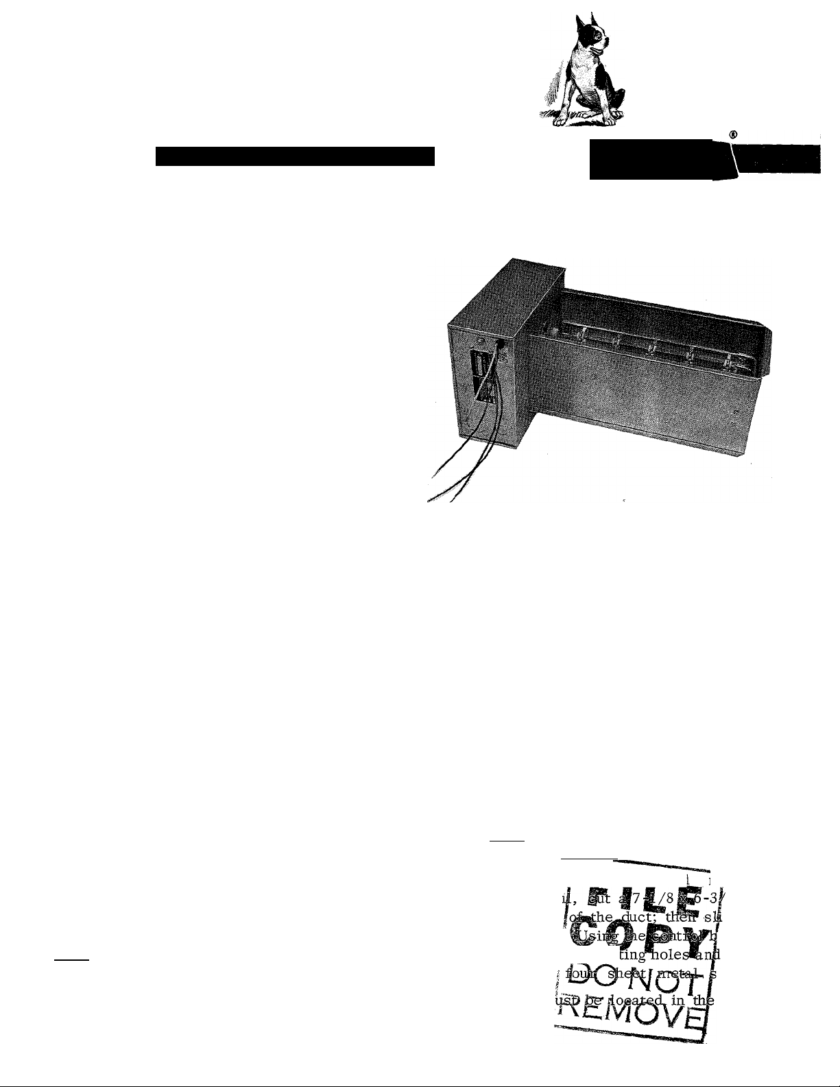
ELECTRIC DUCT HEATER PACKAGE
These instructions are to be used in con
junction with the basic instructions for the
Model 516 Fan Coil Unit. Section II of this
instruction describes the installation of the
electric duct heater package with other than
the Model 516 air handlers .
SECTION I
The electric duct heater is designed to be
used with the Models 18- and 24-516 Fan Coil
Units. Refer to Table I, Ratings and Capaci
ties, for sizes and power inputs. Refer also
to the Dimensional Drawing.
The package, as shipped from the factory,
contains heater coils, a rating plate, a
sequencing relay (for 11- through 14,4-KW
size units), automatic temperature control,
and a manual temperature control switch.
Each heater has both sides of the power line
broken by a main contactor and a backup
contactor, and has an open set of contacts for
fan control.
Before Starting Installation:
1. Check local codes and ordinances for ad
ditional requirements.
2. Check the incoming power supply to be
sure that the rated voltage, frequency, and
phase correspond to that stamped on the unit
ratirig plate.
3 . Check the building power supply to be sure
that it is sufficient to handle the additional
electrical load imposed by this equipment.
b Pliant
39516D3
5/1/69
I
if the heater is to be installed within 6 inches
downstream from the Fan Coil. Mount the
collar on the duct flanges of the Fan Coil so
that the opening for the duct heater is on the
same side of the Fan Coil as the coil con
nections and rating plate. Make certain that
the flange is at the bottom of the duct heater
opening. This will insure that the heater is
placed at the correct depth.
Now, place the heater into the collar and
attach it to the collar with four sheet metal
screws.
If the application does not provide adequate
space for the duct heater to be installed
6 inches from the Fan Coil, then the duct
heater must be installed 48 inches down
stream from the Fgyj-Coil Unit-.
Installing the Electric Duct Heater Package
The duct heater package is designed for zero
clearance from combustible material. There
must be a 7 -1 /2 inch clearance in front of the
control box cover.
A collar for mounting the duct heater is pro
vided with each Fan Coil Unit. Use this collar
To install the he,
from the Fan Co
hole in the side
heater into place
template, drill fo|.r_moun
the heater with
An air filter mi
airstream.
es .downstream
8 inch
de the
Ox as a
attach
crews.
return
Page 2
TOP VIEW
SIDE VIEW
10
D
Electric Duct Heater Dimensional Drawing
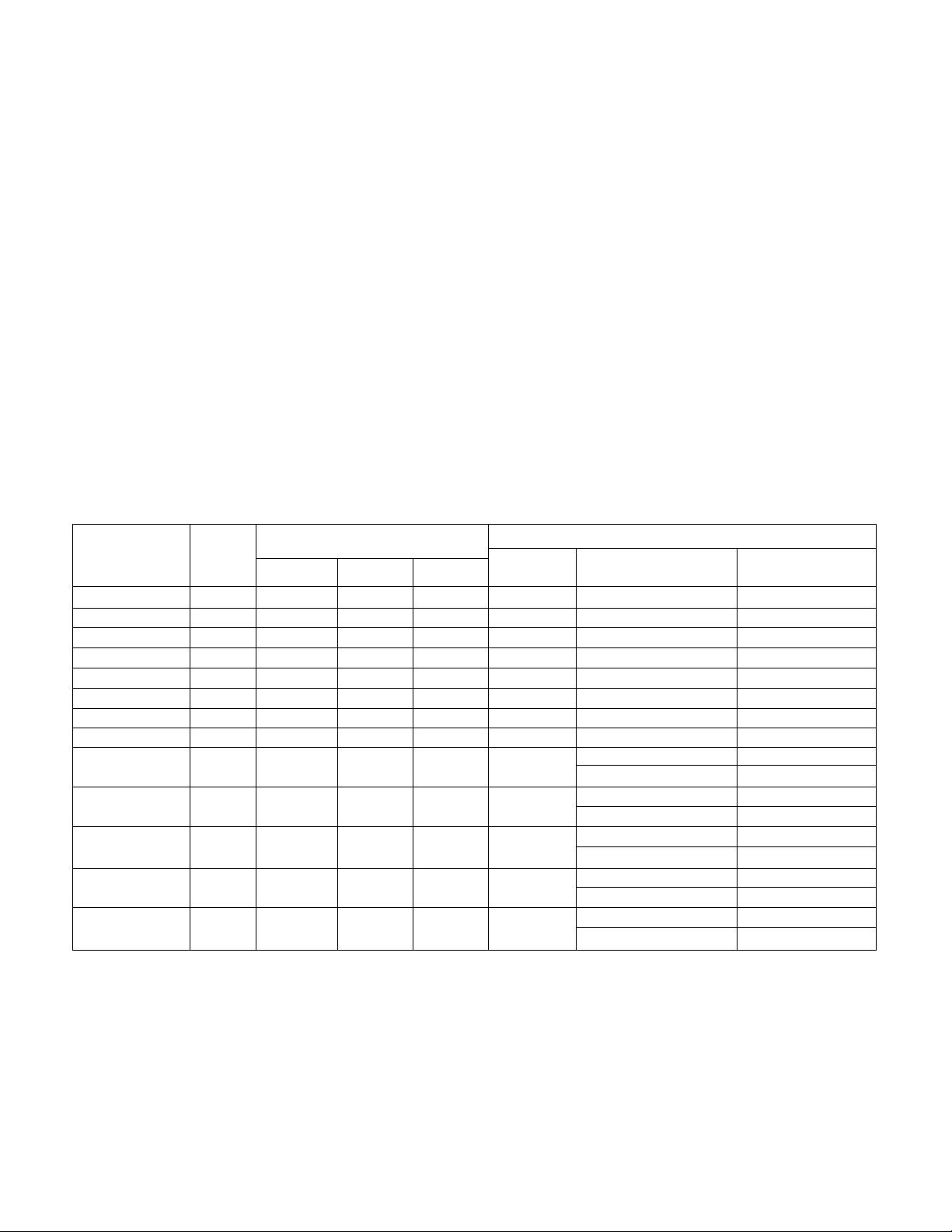
TABLE I - RATINGS AND CAPACITIES
Packoge
P/N
KW
Rating
208 V
65901D03 3
65901D04 4 10,254
65901D05 5
65901D06
65901D07
6
7 17,944 21,941
65901D08 8
65901D09
65901D010
65901D011
65901D012
9 23,071
.9.6
11
12
6590IDO13 13
6590IDO14 14
65901D015 14.4
12,817 15,672 17,065 1
15,381
20,508 25,076
24,610 30,091
28,199 34,479 37,543 2
30,762
33,326
35,889
36,915
* Rated at 240V, 60 cycle, single phase
** Includes blower motor and one heating element
* Capacity Btuh
7,690 9,403 10,239
230V 240V
12,538
18,807
13,652
20,478 1
No. of
Circuits
23,891 1
27,304
28,210
30,717
32,764
37,614
40,956
40,748 44,369
43,883
47,782 2
45,136 49,147 2
«i
o o
Field Wire Connections
Minimum Wire Size
AWG - 90° C - Copper
1
1
12
10
10
10 (2)40
8
1
1
1
8 (2) 50
6 (2) 60
6
10 ** (2) 30
10 (2) 40
2
2
10
8
10 ** (2) 30
8 (2) 50
10 ** (2) 30
8 (2) 50
10
8 - (2) 50
Max Fuse Size
Amps
(2) 20
(2) 20
(2) 30
(2) 50
(2) 60
** (2) 30
(2) 50
** (2) 30
39516D3
-2 -
Page 3

Limitations and Recommendations
1. The duct heaters should never be installed
from the bottom or the top of the duct - only
from the sides of the duct. The heaters must
always be installed on the discharge side of
the Fan Coil.
2. Only one duct heater may be used in any
one duct. If the capacity required exceeds the
output of one duct heater, select the total
number of heaters and proportion them in
separate runouts or separate ducts from the
plenum.
Table II - Air Delivery at Indicated Static Pressure
(Dry Coil, Less Filter)
Evaporator
Model
18-516
24-516
* Static pressure - inches w.c.
Motor
Speed Tap
High 930 920
Medium
Low
High 955
Medium
Low
*0.0
705
605
695
615 605
*0.1 *0.2 *0.3
CFM
890
905
700 690
600 590
940 915
690 680 670
675 650
580
880
600 580
*0.4
860
550
830
680
555
3. Install the duct heater at least 18 inches
away from any canvas duct connector. If the
heater must be located closer, replace the
canvas connector with an asbestos connector.
4 . The control enclosures of the duct heaters
must be completely accessible and so located
as to provide ventilation at all times.
5. The air duct should be installed in ac cordance with the standards of the National
Board of Fire Underwriters for the Instal
lation of Air Conditioning and Ventilating
Systems of other than Resident Type (pamphlet
no. 90A), and Resident-Type Warm Air Heat
ing and Air Conditioning Systems (pamphlet
no. 90B).
6. Each duct heater should be provided with
a fan relay. The heater and fan motor are to
be wired so that the duct heater cannot oper
ate unless the fan is on. Always hook the fan
interlock to the high-voltage side of the
system. Never use a fan delay with the
electric duct heater.
7. The coil of the secondary contactor
(general-purpose, continuous duty rated at
6000 cycles) must be wired in series with the
manual reset limit control (TMR).
NOTE; Observe at least one complete heating
cycle before leaving the installation.
Electrical Connections
Make all electrical connections in accordance
with the National Electric Code and any local
codes or ordinances that may apply.
Provide power supply (or supplies; 11- throu^
14.4-KW heaters will have two power sup
plies) for the heating capacity of the unit
being installed in accordance with Table I Ratings and Capacities. Power supply con
nections are made at the high-voltage termi
nals with wire suitable for at least 90° C
(194°F). It is good practice to ground casing
parts and to check factory wiring connections,
to be sure none were loosened in transit or
installation. Refer to Figures 5, 6, and 7 for
field wiring diagrams.
Thermostat Connection
The electric duct heater and Model 516 Fan
Coil Unit are designed for use with a 24-V
heat-cool thermostat, Bryant Model 883 .
Connect the thermostat and the low-voltage
terminal block on the side of the Fan Coil in
accordance with field wiring diagrams Figures 5, 6, and 7. Set the thermostat
heating anticipator at 0.8 amps .
- 3 -
39516D3
Page 4

Start-up, Adjustment.and Checkout
1. Turn on the electrical supply,
2 . Set the thermostat to call for heat.
3. The sequence of operation for 3 - through
9.6 -KW duct heaters is as follows:
A. When the thermostat calls for heating,
the primary contactor closes. See
Figures 1 and 2 .
B. The fan and heating elements are
energized at the same time.
4. Unit shutdown is as follows:
A. As the thermostat is satisfied, the
primary contactor coil is de-energized.
B. The fan and heating elements are de
energized at the same time .
5. The sequence of operation for 11- through
14.4-KW duct heaters is as follows:
A. When the thermostat calls for heating,
the sequencer is energized. See Figure
3.
B. The fan is energized at the same time.
C . The heating elements are energized in
rapid succession.
6. Unit shutdown is as follows:
A. As the thermostat is satisfied, the
sequencer is de-energized.
B. The heating elements are de-energized
in rapid succession.
C . The blower motor is in operation until
the last heating element is de-ener
gized .
1. The amount of supplementary heat required
may be expressed in terms of KW as follows:
KW required
BTU Heat Loss
3413
2. If the air handling equipment is expressed
in CFM's, then a direct cross-reference can
be made by comparing the temperature of the
air (as it enters the duct heater) to the KW
rating on the chart at the rated CFM. See
Figure 4.
A. Draw a line horizontally from the inlet
air temperature to the KW (BTU) re
quired,
B. From this point of intersection on the
KW line, draw a line down vertically to
establish the CFM. See Table II for the
CFM at a given static pressure.
C. The CFM should never be lower than
the CFM as determined from the chart.
In cases where this is not true, then
the CFM must be increased or the KW
required must be reduced.
3 . In cases where the air handling equipment
is expressed in FPM, convert to CFM by
multiplying the FPM by the duct area.
Example:
Air Velocity = 1000 FPM
Duct Size = 8 X 20 in. = 160 sq in.
Duct Area = - 1.11 sq ft
144
Airflow = 1000 FPM X 1 .11 sq ft = 1110 CFM
Check the control circuit operation. Be sure
that the thermostat turns the unit on and off
when heating contacts are closed, then
opened. Be sure that the thermostat fan
switch (if there is one) turns the blower on
and off when switch is turned on, then off.
Replace all control box covers and outer
cabinet panels.
Minimum Air Velocities
The minimum airflow is directly related to
the inlet air temperature. Consideration must
be given to both the airflow across the heater
and the inlet temperature.
39516D3
SECTION II
If the electric duct heater package is used
with an air handler other than our Model 516
Fan Coil Unit:
1. All previous instructions, limitations, and
recommendations apply to this type of instal
lation .
2 . The duct heater must be mounted 48 inches
downstream from the air handler. It cannot
be mounted 6 inches downstream as on the
Model 516 Fan Coil Unit.
• 4 -
Page 5

1. Transformer
2. Blower motor
3. R2 Contactor
Figure 1 - Wiring Diagram for 3-, 4-, & 5-KW Electric Duct Heater
4. Rl Contactor
5. Cooling fan relay
6. Manual reset limit switch
7. Automatic reset limit switch
8. Heater
1. Transformer
2. Blower motor
3. Contactor R3
4. Heaters
5. Contactor R2
6. Contactor Rl
7. Cooling fan relay
8. Manual reset limit switch
9. Automatic reset limit switch
Figure 2 - Wiring Diagram for 6-, 7-, 8-, 9-, & 9.6-KW Electric Duct Heater
- 5 -
• 39516D3
Page 6

1. Transformer
2« Blower motor
3. Contactor R1
4. Heaters
5. Sequencing relay
6. Contactor R2
7. Cooling fan relay
8. Manual reset limit switch
9. Automatic reset limit switch
Figure 3 - Wiring Diagram ior 11-, 12-, 13-, 14-, & 14.4-KW Electric Duct Heater
39516D3
- 6 .
Page 7

co
Ф
(л
м
Ol
ö
со
Page 8

ю
сл
н*
о\
Ö
00
Page 9

0
VJ
3
(О
2
Q*
<Û
•Ч
O
Э
r
0
a.
2L
01
Os
K>
CO
\o
en
H»
<J\
Ö
00
m
0
n
O
c
O
 Loading...