


installation, start-up and
service instructions
CEILING
SINGLE PACKAGE COOLING UNITS
PA C
™ HORIZONTAL INDOOR
Cancels: II 502A-24-1 II 502A-36-1
502A
Sizes 036-060
3 to 5 Tons
12/15/05
CONTENTS
SAFETY CONSIDERATIONS . . . . . . . . . . . . . . . . . . . . . . . . . 1
GENERAL . . . . . . . . . . . . . . . . . . . . . . . . . . . . . . . . . . . . . . . . 1
INSTALLATION . . . . . . . . . . . . . . . . . . . . . . . . . . . . . . . . . . .1-6
I. Step 1 — Receive and Inspect Unit . . . . . . . . . . . . . 1
II. Step 2 — Protect Unit from Damage . . . . . . . . . . . . 1
III. Step 3 — Provide Unit Support. . . . . . . . . . . . . . . . . 1
IV. Step 4 — Rig and Place Unit. . . . . . . . . . . . . . . . . . . 4
V. Step 5 — Make Piping Connections. . . . . . . . . . . . . 4
VI. Step 6 — Install Ductwork. . . . . . . . . . . . . . . . . . . . . 4
VII. Step 7 — Make Electrical Connections . . . . . . . . . . 4
VIII. Splitting Systems. . . . . . . . . . . . . . . . . . . . . . . . . . . . 4
IX. Field Control Wiring. . . . . . . . . . . . . . . . . . . . . . . . . . 5
X. Thermostat Wire . . . . . . . . . . . . . . . . . . . . . . . . . . . . 5
XI. Step 8 — Fan Speed . . . . . . . . . . . . . . . . . . . . . . . . . 5
START-UP . . . . . . . . . . . . . . . . . . . . . . . . . . . . . . . . . . . . . . . . 6
SERVICE . . . . . . . . . . . . . . . . . . . . . . . . . . . . . . . . . . . . . . . .7,8
SAFETY CONSIDERATIONS
Installing and servicing air-conditioning equipment can be
hazardous due to system pressure and electrical components. Only trained and qualified service personnel should
install, repair, or service air-conditioning equipment.
Untrained personnel can perform basic maintenance functions such as cleaning c oils and filters an d replaci ng filters.
All other operations should be performed by trained service
personnel. When working on air-conditioning equipment,
observe precaution s in the lit erature and o n tags and labe ls
attached to unit.
Follow all safety codes. Wear safety glasses and work gloves.
Use quenching cloth for unbrazing operations. Have fire
extinguisher avail abl e.
WARNING: Before performing service or maintenance operations on unit, turn off main power switch
to unit. Electrical shock can ca use personal injury.
NOTE: Ensure voltage on unit agrees with voltage listed on
the unit rating plate.
GENERAL
The 502A036,048, and 060 units are single-package, indoor,
horizontally mounted air conditioners of 3, 4 and 5 tons
capacity, respectively.
These units can be mounted as factory-shipped singlepackage units or can be separated and mounted as a split
system. If unit is spl it, the co nden ser sec tio n c a n be m oun ted
horizontally.
All units are designed to be ducted on both the condenser
and evaporator sides. Centrifugal blowers are used to ensure
quiet air delivery to the conditioned space. Sound level
requirements should be determined before final unit installation site is chosen.
Unit servicing is relatively simple since access to the condenser and evaporator motors, blowers, belt, and pulley is
gained through removable swing do ors located on bottom of
unit. These d oo rs may al so b e u s ed fo r cl ea n ing o f co nde n ser
coils. Unit side panels provide access to control box and pressure switches.
Refrigeration cycle components (e.g., compressor, filter
drier, etc.) can be serviced upon removal of the base unit
from the space.
INSTALLATION
WARNING: Determine building alterations required
to run piping, wiring, and ductw ork. Follow dimensiona l
drawings carefully for ductwork, piping locations,
electrical wiring, and overall unit dimensions. Read all
installation instructions before starting installation.
The 502A units are intended f o r indoor instal lation only.
I. STEP 1 — RECEIVE AND INSPECT UNIT
Unpack and check unit against shipping order. Inspect carefully for concealed shipping damage. If unit is damaged or
incomplete, file claim with transportation company and
advise Bryant immediately.
II. STEP 2 — PROTECT UNIT FROM DAMAGE
To maintain warranty, unit must be protected against theft
and vandalism and stored indoors at all times.
III. STEP 3 — PROVIDE UNIT SUPPORT
Refer to Fig. 1 and 2 for unit dimensions and component
locations. Refer to Table 1 for unit sizes and weights.
Each unit requires the following field-supplied items:
4 — threaded suspension rods (
minimum)
4—washers
4 — locknuts
Install the 4 field-supplied rods by suspending them from a
suitable ceiling support. Locate rods to mate with 4 outside
corner rigging holes shown in Fig. 1 and 3.
The ceiling and ceiling supports of existing buildings may
require reinforcements ; follow all applicable codes.
3
/8-in.-16 SAE Grade 1
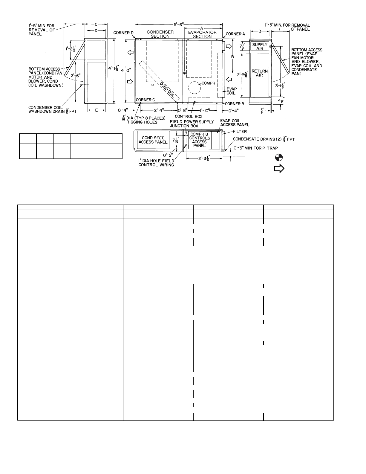
DIMENSIONS (ft-in.)
UNIT
502A
036 2-4
048 2-5 2-3 1-11
060 2-43/42-23/41-115/81-77/81-77/
ABCDE
3
/42-2 1- 53/41-2 1-1
5
/81-87/81-77/
8
8
LEGEND
Center of Gravity
Direction of Airflow
Fig. 1 — Dimensions
Table 1 — Physical Data
UNIT 502A 036 048 060
OPERATING WEIGHT (lb)
Base Unit, Evap/Condenser Section 480, 206/274 580, 250/330 590, 254/336
SHIPPING WEIGHT (lb)* 590 690 700
REFRIGERANT TYPE R-22
Operating Charge (lb)† 5.5 8.0 7.6
COMPRESSOR — TYPE Scroll
Quantity...Model (1)...ZR34 (1)...ZR49 (1)...ZR57
Oil (oz) 42 48 54
HPS Setting (psig)
Cutout 426 ± 7
Reset 320 ± 20
LPS Setting (psig)
Cutout 27 ± 4
Reset 67 ± 7
CONDENSATE DRAIN CONNECTION
Size (in.)...Type
CONDENSER FAN Centrifugal — Belt Drive
Nominal Cfm 1350 2250 2450
Maximum Rpm 1100 1500
Blower Size (in.) 12 x 6 12 x 9
Pulley Pitch Diameter (in.)
Blower 5.0 6.0 6.0
Motor (Variable) 2.4-3.4 1.9-2.9 2.4-3.4
Motor Hp
Motor Rpm 1725 1725 1725
EVAPORATOR AIR FAN (Standard) Centrifugal — Direct Drive
Nominal Cfm 1200 1600 2000
Max Rpm 1150 1050
Blower Size (in.) 10 x 6 10 x 6
Motor Hp (Rpm)
EVAPORATOR AIR FAN (Optional)
Nominal Cfm 1600 2000
Max Rpm 1300
Blower Size (in.) 10 x 8
Motor Hp 1
Motor Rpm 1725
Pulley Pitch Diameter (in.)
Blower 4.2
Motor (Variable) 2.4-3.4
CONDENSER COIL Copper Tubes — Aluminum Fins
Size (L x H) (in.) 40 x 16 40 x 22
Number of Rows...Fins/in. 4...17 4...13.6
EVAPORATOR COIL Copper Tubes — Aluminum Fins
Size (L x H) (in.) 34 x 16 34 x 22
Number of Rows...Fins/in. 4...15 4...14.4
INDOOR-AIR FILTERS Factory-Supplied Cleanable Type
Number...Size (in.)
INTERCONNECTING TUBING SIZE (in.)**
Hot Gas
Liquid
HPS — High-Pressure Switch
LPS — Low-Pressure Switch
*Shipping weights include base unit plus packaging.
†If components are to be split, additional refrigerant will be needed. Refer to Fig. 5-7 for
charging charts.
LEGEND
3
/
4
1
/2 (1075)
Not
Available
1...14 x 34 x 1
1
/
2
3
/
8
**Use Type L copper only.
NOTE: If components are to be split, the maximum length of refrigerant tubing to be
used is 50 equivalent ft, assuming components will be installed in same horizontal plane.
If components are not to be installed in same horizontal plane, contact your Bryant representative for more information.
3
/4...FPT
11
3
/4 (1050)
Centrifugal Belt Drive
1
/
2
1...21 x 34 x 1
1
/
2
3
/
8
1
/
2
1
/
2
3
/
8
—2—
CONTROL BOX ACCESS PANEL,
COMPRESSOR, LOW-PRESSURE AND
HIGH-PRESSURE SWITCHES AND
SERVICE PORT CONNECTION
ACCESS
JUNCTION BOX
CONDENSER
SIDE ACCESS
PANEL
FILTER DRIER AND
CAPILLARY TUBE ACCESS
FILTER
CONTROL BOX
FILTER
DRIER
UNIT WITH FILTER
REMOVED
CONDENSER MOTOR
AND BLOWER ACCESS-ALSO
PROVIDES ACCESS FOR
CLEANING CONDENSER COIL
EVAPORATOR MOTOR
AND BLOWER ACCESS-ALSO
PROVIDES ACCESS FOR
CLEANING EVAPORATOR
CONDENSER MOTOR AND
BLOWER ASSEMBLY
EVAPORATOR MOTOR
ACCESS DOORS
Fig. 2 — Component Locations
UNIT 502A
036 28.8 26.0
048 29.0 27.0
060 28.8 26.8
NOTE: Fasten threaded rods through holes in end frames as shown.
Use 2 rods on each side of unit for a total of 4.
CAUTION: All panels must be in place when rigging.
Fig. 3 — Rigging Details
—3—
CENTER OF GRAVITY
DIMENSIONS (in.)
AB

IV. STEP 4 — RIG AND PLACE UNIT
Move and store unit in horizontal position. Provide space
around unit for service, filter access, ductwork, and overhead
clearance as indicated in Fig. 1.
Using suitable hydraulic lift source, raise unit up to meet
bottom of the 4 threaded rods suspended from ceiling. Center
unit so that the 4 threaded rods can be easily i nserted into
the factory-drilled holes at each end. Refer to Fig. 3 for rigging details.
Apply washers and locknuts on ends of each of the 4 rods.
Tighten locknuts sufficiently so that unit weight is sup-
ported entirely by the 4 rods. Level unit within the space by
adjusting locknuts.
IMPORTANT: Unit must be level to operate properly.
NOTE: Th e 2 factory-drilled holes in the middle of th e unit
can be used for support if a split system application is
desired. If re q uir e d, a v ibration isola tor pack ag e acce s so ry is
available for use to minimize vibration that may be transmitted to building structure.
NOTE: For split systems, 8 suspension rods are required.
Refer to Splitting Systems section.
V. STEP 5 — MAKE PIPING CONNECTIONS
3
Two
/4-in. pipe thread condensate drain connections are provided below the evaporator coil. One 3/4-in. pipe thread connection is provided for condenser coil washdown. One of the
evaporator drains is plugged at the factory; plug must be
removed when making field connections. The condenser
washdown pan is plugged at the factory. This drain is to be
used only when condense r co il i s be ing c l ea ned; plug must be
replaced when cleaning is completed.
VI. STEP 6 — INSTALL DUCTWORK
Use flexible ductwork to attach duct to unit and to help control transmission of vibrations to building structures. Attach
ductwork to the return and supply ends of both coils.
If unit is located with condenser close to outside of building,
install a field-supplied rainhood. Hood intake dimensions
should be same as condenser return-air dimensi ons. In addition, install a tr iple-layer bird s cre en over rainhood in take t o
eliminate possibility of insects, birds, water, or debris from
entering unit. Ensure hood and/or louvers are installed correctly to avoid condenser air recirculation.
VII. STEP 7 — MAKE ELECTRICAL CONNECTIONS
Provide and install a safety discon nect switch i n accordance
with National Electric Code (NEC) and all local codes.
Connect power wiring to junction box located on unit side
near control box access panel. All wiring must comply
with NEC and all local code re qui re me nt s.
Operating voltage to compressor must be within voltage
range as indicated on unit nameplate. Voltages between
phases must be balanced within 2% and current must be
balanced within 10%. Contact local power company for
correction of improper voltage or phase imbalance. Unit
failure as a result of operation on improper line voltage or
excessive phase imbalance constitutes abuse and may cause
damage to electrical components. Such operation would
invalidate any applicable Bryant warranty.
Refer to unit nameplate and Table 2 for fuse sizes and wire
amperages for all units.
VIII. SPLITTING SYSTEMS
The 502A roomtop units may be split into 2 sections, if
desired, with condensing section mounted remotely either
horizontally or vertically. If sections are installed in same
horizontal plane they may be separated by up to 50 equivalent ft of tubing. Use type L copper or better.
Condensing section must be located in same plane as, or
above, evaporator section to maintain the liquid refrigerant
seal at the expansion device. This permits expansion device
to feed liqu id ref rige rant to ev apor ator coil p rop erly. To split
sections (some of the following steps may be eliminated
depending on particular application):
1. Disconnect all electrical power to unit and tag
disconnect.
2. Remove 4 bolts connecting the 2 sections.
3. Remove top panels from each section.
4. Recove r the refrigerant from the system using both
the high and low-pressure ports.
5. Cut refrigerant piping in the evaporator section just
inside the partition between the 2 sections.
Table 2 — Electrical Data
UNIT
502A
036
048
048*
060
060*
HACR — Heating, Air Conditioning, and Refrigeration
Hp — Horsepower
FLA — Full Load Amps
LRA — Locked Rotor Amps
MOCP — Maximum Overcurrent Protection (HACR breaker)
RLA — Rated Load Amps
V-P H
(60 Hz)
208/230-3 187 254 10.2 77.0 .50 3.20 .75 3.93 19.9 25
460-3 414 508 4.3 37.0 .50 1.50 .75 1.97 8.8 15
208/230-3 187 254 13.5 99.0 .75 4.00 1.0 3.93 24.8 35
460-3 414 508 7.4 49.5 .75 2.15 1.0 1.97 13.4 15
575-3 518 632 5.8 40.0 .75 1.40 1.0 1.45 10.1 15
208/230-3 187 254 13.5 99.0 1.5 5.60 1.0 3.93 26.4 35
460-3 414 508 7.4 49.5 1.5 2.80 1.0 1.97 14.0 20
208/230-3 187 254 17.3 123.0 .75 4.00 1.5 4.82 30.4 45
460-3 414 508 9.0 62.0 .75 2.15 1.5 2.41 15.8 25
575-3 518 632 7.1 50.0 .75 1.40 1.5 1.90 12.2 20
208/230-3 187 254 17.3 123.0 1.5 5.60 1.5 4.82 32.0 40
460-3 414 508 9.0 62.0 1.5 2.80 1.5 2.41 16.5 25
VOLTAGE RANGE COMPRESSOR
Min Max RLA LRA Hp FLA Hp FLA
LEGEND *Optional evaporator-fan motor nameplate data.
—4—
FAN MOTORS POWER SUPPLY
Evaporator Condenser
Min Ckt
Amps
MOCP
Amps

6. Unsweat the cut portions of the refrigerant piping in
evaporator sect ion at the closest bell joint. The bell
joints are used to connect field-supplied refrigerant
piping to evaporator section. Cut and braze a length
of tubing to extend refrigerant piping outside the
evaporator section.
7. Cut condenser-fan motor wiring at the partitions separating co ndenser and evaporator sections.
8. In the condenser section, install a junction box adjacent to the D-shaped grommet.
9. Install evaporator and condensing sections in desired
locations. Refer to Steps 10-12 below.
10. Use appropriate length of no. 16 American Wire Gage
4
(AWG) (minimum),
/64-in. insulated copper wire to
reconnect cut condenser-fan motor wi res. Make connections in junction boxes installed in earlier steps.
Follow all applicable electrical codes.
11. Use sufficient length of refrigerant piping to reconnect piping cut in previous step. Liquid line tubing is
3
/8-in. OD copper tubing, and hot gas line is 1/2-in. OD
copper tubing.
12. Replace top panels on eac h sect io n.
13. Evacuate refrigerant system to 500 microns.
14. Recharge unit with R-22 refrigerant following
Charging Charts (p age 8) in these instruction s. Use
refrigerant charge as indicated on unit.
NOTE: National Electric Code (NEC) disconnects are
required at each section if units are not installed within line
of sight of each other.
After splitting sections, additional refrigerant must be added
to system to ensure proper refrigerant charge. The amount of
refrigerant to be added depends on length of tubing added to
system and opera ting tem perature s of syst em. Allo w unit to
operate at least 10 minutes before adjusting refrigerant
charge.
Since standa rd roomt op u nit has negl igib le li ne lo sses, spli tting the system can increase line loss and decrease system
capacity.
IX. FIELD CONTROL WIRING
Install a Bryant-approved thermostat assembly accessory
according to i n stallation instruct i on s p r ovid e d by t he r mo st at
manufacturer. Locate thermostat assembly on a solid wall in
the conditioned space away from drafts to sense average
room temperature.
Using thermostat cable or equivalent single leads of no. 18
AWG colored wire, route cable or wire from the subbase terminals, up and through connector on unit side (below power
lead junctio n box) a nd conn ect to low-volt age ter minal block
inside the control box.
X. THERMOSTAT WIRE
Use 18 gage for 0 to 50 ft long wires and 16 gage for 51 to
75-ft wire lengths.
XI. STEP 8 — FAN SPEED
Adjust condenser fan speed and evaporator fan s pee d to m ee t
job requirements. Enter the condenser and evaporator sections through the hinged access panels on the bottom of
units (see Fig. 2). S ee Service section of this docum ent for
general service procedures.
A. Evaporator-Fan Motors
Standard evaporator fans are direct-driven designs. Size 036
units have single-speed motors and require no adjustment.
Sizes 048 and 060 units use two-speed fan motors. Refer to
Table 3 for standard evaporator fan performance. The evaporator fan motor factory speed select ion is shown on the label
diagram affixed to base unit. If other than factory speed setting is desired, refer to label diagram for motor reconnection.
Optional evaporator fan drives (for unit sizes 048 and 060)
are belt-drive designs. Refer to Table 4 for optional evaporator fan performance. Adjust the motor pulley setting as
required to provide the project design evaporator airflow
rate. Pulley setting must limit the airflow rate to maximum
of 2250 cfm.
See Service sectio n for instructions on che cking motor shaft
and fan shaft alignment, pulley alignment and belt tension.
B. Condenser-Fan Motors
Condenser-fan motors are belt driven. Fan speed must be
adjusted to maintain condenser airflow at the flow rate
specified in Table 1. Refer to Table 5 for condenser fan performance data. See Note 6 for factory drive pulley settings.
Adjust the motor pulley setting as required to provide design
condenser airflow through the si te’s cond enser duct system.
Table 3 — Evaporator-Fan Performance
UNIT SIZE — 502A
AIRFLOW
(cfm)
900 .69 .44 — — — —
1000 .57 .46 — — — —
1100 .42 .49 1.10 .45 1.11 .52
1200 .23 .52 1.01 .49 1.045 .55
1300 — — .90 .51 .97 .57
1400 — — .79 .55 .88 .59
1500 — — .67 .58 .78 .62
1600 — — .54 .61 .67 .64
1700 — — .39 .64 .53 .67
1800 — — .22 .67 .52 .70
1900 — — .03 .70 .40 .74
2000 —— —— .28 .78
ESP — External Static Pressure (in. wg)
kW — Total Fan Motor Power Input (kilowatts)
*Standard direct drive indoor-fan motor (IFM). For optional belt drive
IFM performance, see following table.
NOTES:
1. Above fan performance is based on wet coil and deducted casing
losses, and clean factory-installed permanent cleanable filter.
2. Evaporator fans are direct drive (except sizes 048, 060 indoor-fan
motor option).
3. Interpolation is permissible, do not extrapolate.
036 048* 060*
ESP
LEGEND
Fan
kW
ESP
Fan
kW
ESP
Fan
kW
Table 4 — Optional Belt-Drive
Evaporator-Fan Performance
AIRFLOW
(cfm)
1800 ————
1850 ————
1900 ————
1950 .81 1.03 — —
2000 .72 1.05 — —
2050 .63 1.07 — —
2100 .55 1.08 1.02 1.17
2150 .47 1.11 .93 1.21
2200 .42 1.14 .84 1.24
2250 .34 1.17 .75 1.27
NOTE: Pulley setting must be adjusted to limit cfm to 2250 cfm
maximum
condensate problems.
. Unit operation beyond that limit may result in blow-off and
ESP Fan kW ESP Fan kW
UNIT SIZE — 502A
048 060
—5—

Table 5 — Condenser-Fan Performance
UNIT
502A
036
048
060
kW — Total Fan Motor Power Input (kilowatts)
NOTES:
1. Above fan performance is based upon coil and deducted casing losses only.
2. External static pressure (ESP) is measured in inches water gage (in. wg).
AIRFLOW
(cfm)
1650 2 .84————————————
1600 — — 2 .82——————————
1550 — ——— 2 .80————————
1500 3 .72 — — — — 2 .78 1 .84 — — — —
1450 4 .63 3 .70 — — — — 2 .76 1 .83 — —
1400 — — 4 .61 3 .68 — — — — — — 1 .81
1350 5 .51 — — — — 3 .67 — — 2 .73 — —
1300 — — 5 .50 4 .57 — — 3 .65 — — 2 .71
2700 2 .90————————————
2600 — — 2 .87——————————
2550 3 .81————————————
2450 — — 3 .77 2 .83 1 .89 — — — — — —
2350 — ————— 2 .801 .86————
2300 4 .68 — — 3 .74 — — — — 0 .90 — —
2200 — — 4 .66 — — — — 2 .77 1 .82 0 .86
3100 31.34————————————
3000 — — 31.32——————————
2900 — ————— 21.39——————
2850 4 1.11 — — 3 1.24 — — — — — — — —
2750 — — 4 1.07 — — — — 2 1.32 — — — —
2700 — ————— 31.17——————
2650 — ——————————— 11.37
2600 5 .95 — — 4 1.01 — — — — 2 1.26 — —
2550 — ——————— 31.12————
2500 — — 5 .92——————————
2450 — — — — — — 4 .97 — — — — 2 1.21
2400 — — — — 5 .90 — — — — 3 1.08 — —
LEGEND
0.0 0.1 0.2 0.3 0.4 0.5 0.6
Turns kW Turns kW Turns kW Turns kW Turns kW Turns kW Turns kW
EXTERNAL STATIC PRESSURE (in. wg)
3. Interpolation is permissible. Do not extrapolate.
4. Minimum one turn open of motor pulley is required on unit sizes 036 and 060.
5. Number of turns open applies to field setting of motor pulley.
6. Factory setting as follows: 036, 4 turns open; 048, 2 turns open; 060, 5 turns
open.
START-UP
I. UNIT PREPARATION
Make sure unit has been install ed in ac corda nce with ins tallation instructions and applicable codes.
II. COMPRESSOR MOUNTING
Compressors are internally spring mounted. Do not loosen or
remove compressor holddown bolts.
III. INTERNAL WIRING
Check all electrical connections in unit control boxes and
tighten as required. Be sure wires are not in contact with
sharp edges or refrigerant tubing.
IV. REFRIGERANT SERVICE VALVES
Each unit system has 3 Schrader-type service ports, one on
the suction line, one on the compressor discharge line, and
one for low-ambient damper kit. Be sure that caps on the
ports are tight. One Schrader-type valve is located under
both the high-pressure switch and low-pressure switch.
V. COMPRESSOR ROTATION
It is important to be certain compressor is rotating in the
proper direction. To determine whether or not compressor is
rotating in the proper direction:
1. Connec t service gages to suctio n and discharge pressure fittings.
2. Energize the compressor.
3. The suction pressure should drop and the discharge
pressure should rise, as is normal on any start-up.
If the suction pressure does not drop and the discharge pressure does not rise to normal levels:
1. Note that the co ndenser fan may also be rotating in
the wrong direction.
2. Turn off power to the unit and tag disconnect.
3. Reverse any two of the unit power leads.
4. Reapply power to the unit; remove tag. Energize
compressor.
5. Verify correct refrigerant pressures.
The suction and discharge pressure levels should move to
their normal start-up levels.
NOTE: When the compre ssor is rotating in the wrong direction, the unit will sound louder than normal and will not
provide cooling.
VI. FAN ROTATION
Check fan rotation to ensure progression in proper direction.
VII. COOLING
To start unit, turn on main power supply. Set system selector
switch at COOL position and fan switch at AUTO. position.
Adjust thermostat to a setting below room temperature.
Compressor, condenser and evaporator motors start on closure of contactors.
A. To Shut Off Unit
Set system selector switch at OFF position or reset thermostat at a position above room temperature. Units are
equipped with Cycle-LOC™ protective device.
Cycle-LOC™ device prevents an automatic restart of a unit’s
compressor that has been shut down due to a safety device
trip. The Cycle-LOC device may cause an indicator light on
the thermostat subbase to illuminate upon a safety trip (if
the thermostat i ncludes this feature).
Be sure to check reason for safety trip befor e resetting the
Cycle-LOC device. Compressor restart is accomplished by
manual reset at the thermostat by first turning the selector
switch to OFF and then back to ON position.
—6—

SERVICE
WARNING: Electrical shock can cause personal
injury. Open al l remote discon nects and tag before servicing this equipment.
IMPORTANT: If repai rs t o refrig era nt cycle com pone nt s (e.g.,
compressor, filter drier, etc.) are requir ed, recover all refri gerant from the system by using bo th high- pressure a nd lowpressure ports, then remove base unit from the space.
I. COMPONENT LOCATION AND ACCESS
Refer to Fig. 2 for component locations and access panel locations. If a suspended ceiling has been installed beneath the
unit, the hinged access panels may not open fully. Remove
the panels at the hinged sides to provide full access.
II. FILTERS
Filters are clean abl e an d s hou l d b e ins pecte d a n d cle ane d at
regular intervals monthly or as conditions require. Filters
can be washed with wate r or v acuum ed as ne eded. They are
located in front of the evaporator coil and may be removed by
sliding them horizontally out to edge of unit. See Fig. 1 and
2. No tools are required for installation or removal of filters.
III. CONDENSER COIL
The condenser coil is accessible through the bottom access
door marked condenser secti on, o r thro ugh side a cce ss pan el
on condenser section, or through side access panel on condenser section. Use a stiff brush when cleaning coil. Be careful not to bend aluminum fins.
Connect the condenser washdown pan drain connection
3
(
/4-in. FPT) to the building drain using a 3/4-in. MPT hose.
Entering through unit bottom condenser access door, use a
water hose or other suit able equipm ent to f lush ou t dirt an d
wash do wn co il. Be careful not to force water spillage out of
condenser washdown pan.
IV. EVAPORATOR COIL
The evaporator coil is accessible for cleaning through the
bottom access door marked “Evaporato r Section.” When necessary, wash co il with a commercial cleane r (Oakite 164) or
dishwasher detergent using a pressurized spray canister.
Flush coil from return -air duct side and tak e care not to get
water in ductwork or unit insulation.
V. CONDENSATE DRAIN
Clean and empty drain pan at least once a year to prevent
sludge build-up.
VI. LUBRICATION
Lubrication of the condenser and evaporator motors is not
necessary since both are equipped with p ermanently lubricated bearings. Do not oil.
VII. MOTOR SPEED ADJUSTMENT
Direct-drive evaporator motors require no adjustment.
VIII. CONDENSER MOTOR
All 502A036-060 units contain belt-driven adjustable-pulley
condenser fan systems. All 502A048 unit fan motors are
shipped with adjustable pulley 2 turns open and 502A060
units are shipped at 5 turns open, and can be adjusted to
increase fan speed. The 502A03 6 u nit fan m otors ar e shi pped
with adjustable pulley at 4 turns open.
IX. BLOWER WHEEL SERVICING
In-space servicing is recommended for the evaporator and
condenser blowers. Both are removed by loosening and
removing the 4 screws that hold them in place. In both cases,
the entire ass embly is then moved outside of the b ase unit.
Once outside, the blower wheel and condenser shaft bearings
and/or evaporator motor can be serviced.
X. BELT-DRIVE FAN ADJUSTMENTS
Follow these instructions for adjusting motor pulley pitch
setting (to change fan speed), for aligning motor shafts and
pulleys, and for adj usting belt tension on all belt-drive fan
systems.
To change the fan speed:
1. Shut off unit power supply, tag disconnect(s).
2. Loosen belt by loosening fan motor mounting bolts.
3. Loose movable flange setscrew (see Fig. 4).
4. Screw movable flange toward fixed flange to increase
speed and away from fixed flange to decrease speed.
Increasing fa n speed inc reases lo ad on fan m otor. Do
not exceed maximum speed specified in Table 1.
Observe maximum evaporator flow rate limits per
note on Table 4.
5. Set movable flange at nearest keyway of pulley hub
and tighten setscrew.
6. Tighten fan motor mounting bolts.
To align fan and motor shafts, loosen motor from mounting
and reposition as necessary. To align fan and motor pulleys,
loosen fan pulle y setscrew s on fan sh aft and sli de fan pul ley
along shaft until straightedge check confirms alignment (see
Fig. 4). Tighten setscrews. Check all motor mounting bolts.
To adjust belt tension:
1. Loosen fan motor mounting bolts.
2. Slide motor away from fan shaft for proper belt ten-
1
sion (
/2-in. deflection with 8 to 10 lb of force) and
tighten motor mounting bolts.
XI. BLOWER BELT ADJUSTMENT
Inspect blower b elt for wear, proper belt tension, a nd pulley
alignment as conditions require or at the beginning of each
heating and air conditioning season. Refer to Step 8 — Fan
Speed on page 5 for adjustment and alignment procedures.
XII. CONTROL BOX SIDE ACCESS PANEL
The control box side access pa nel is held i n place wi th
1
/4-in.
self-retaining fasteners. When these fasteners are pulled,
the access panel can be t urned around 180 degre es so that i ts
metal lip w ill line up wit h the metal lip on bottom of uni t.
This enables the access panel cover to hang down, exposing
the base unit wiring diagram and enabling the service person to work more freely.
Fig. 4 — Evaporator-Fan Pulley Adjustment
—7—

XIII. REFRIGERANT CHARGE
Amount of refrigerant charge is listed on unit nameplate
(also refer to Table 1).
Unit panels must be in place when unit is operating during
charging procedure. Unit must operate for at least 10 minutes before adjusting charge.
A. No Charge
Use standard evacuating techniques. After evacuating system, weigh in the speci fied amount of refrig erant. (Refer to
Table 1.)
B. Low Charge Cooling
Using Cooling Charging Charts, Fig. 5-7, vary refrigerant
until the conditions of the appropriate chart are met. Note
the charging charts a re different from type normall y used.
Charts are based on charging the units to the correct supe rheat for the var ious op erating c onditio ns. Accurate pr essure
gage and temperature sensin g device are required. Connec t
the pressure gage to the service port on the suction line.
Mount the temperature sensing device on the suction line
and insulate it so that surrounding ambient temperature
does not affect the reading. Indoor-air cfm must be within
the normal operating range of the unit.
B. To Use Cooling Chart
Take the am bient temp eratu re and re ad th e sucti on press ure
gage. Refer to appropriate chart to determin e what suction
temperature should be. If suction temperature is high, add
refrigerant. If suction temp erature is low, carefully recove r
some of the charge. Recheck the suction pressure as charge
is adjusted.
Example: (Fig. 5)
Ambient Temperature . . . . . . . . . . . . . . . . . . . . . . . . .85 F
Suction Pressure . . . . . . . . . . . . . . . . . . . . . . . . . . 70 psig
Suction Temperature should be . . . . . . . . . . . . . . . . .47 F
(Suction Temperature may vary ± 5 F.)
Fig. 6 — Charging Chart —502A048
Fig. 7 — Charging Chart — 502A060
Fig. 5 — Charging Chart — 502A036
Copyright 2005 Bryant Heating & Cooling Systems Printed in U.S.A. CATALOG NO. 04-53502001-01
 Loading...