

Page 1
4-Way Multipoise
Induced Combustion
Gas Furnace
311AAV/311JAV
Sizes 045 thru 155
Series A
The Plus 80 311AAV/JAV Deluxe 4-Way Multipoise
Gas Furnace offers outstanding features in an 80%
AFUE furnace. Deluxe features include: third fan
relay for discrete continuous fan speed, the ability to
change continuous fan speeds from the thermostat,
dehumidify mode, standard Media Filter Cabinet, fault
code storage, and more. The Plus 80 is very quiet
thanks to a new combustion design that eliminates
noise, rather than just muffle or box it in. Applications
are easy with 4-way mulitpoise design, through-thefurnace downflow venting, 13 different venting options,
and a door designed for easy service access. An inner
blower door is provided for tighter sealing in sensitive
applications. The 311AAV/JAV furnace is approved for
P
LUS
80
E
n
e
r
g
y
E
ff
i
c
i
e
n
t
G
a
s
Fur
n
a
c
e
use with natural or propane gas, and the 311JAV is
approved for use in LowNOx Air Quality Management
Districts.
ama
A02180
CERTIFIED
REGISTERED
QUALITY SYSTEM
MEETS DOE RESIDENTIAL CONSERVATION
SERVICES PROGRAM STANDARDS.
Before purchasing this appliance, read important
energy cost and efficiency information available
from your retailer.
STANDARD FEATURES
.
Four-position furnace: upflow, horizontal right,
horizontal left, downflow
Thirteen different vent options
.
Noise elimination combustion system
.
Media Filter Cabinet included
.
Microprocessor based "smart" control
center
"Fan On PlusTM" Continuous Fan speed adjustable
from thermostat
Dehumidify mode
Adjustable heating air temperature rise
LED diagnostics and self test feature
Non-volatile fault code storage
.
Patented blocked vent safeguard to ensure
proper furnace venting
.
All models are Chimney Friendly when used
with accessory vent kit
.
Insulated blower compartment
Shorter unit height, only 331/3" tall
.
Heat pump compatible
.
Hot surface Ignition (HSI)
.
Residential installations eligible for
consumer financing through the Comfort
Credit Program
.
Twinning in Upflow, Downflow, and Horizontal
LIMITED WARRANTY
.
20-year warranty on "Super S
.
5-year parts warranty on all other components
TM
" heat exchanger
Form No. PDS 311A.45.2
Page 2
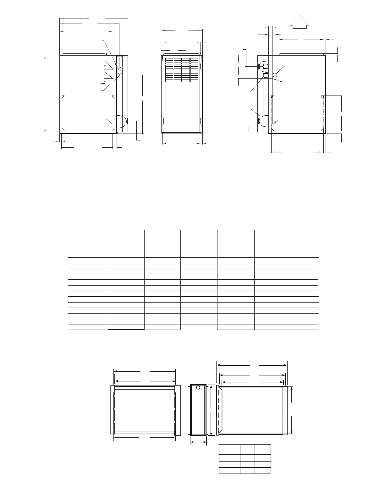
33-5/16"
E
VENT
28-7/8"
25-1/4"
22-9/16"
JUNCTION BOX
LOCATION
7/8" DIA
ACCESSORY
1/2" DIA THERMOSTAT
WIRE ENTRY
3-15/16"
LEFT HAND GAS
ENTRY
7/8" DIA. ACCESSORY
24-7/8"
A
D
13/16"
F
JUNCTION BOX
LOCATION (TYP)
VENT OUTLET
5 PLACES (TYP)
1-9/16"
2-9/16"
4-13/16"
8-7/16"
1-7/16"
ALTERNATE
3-3/4"
AIRFLOW
19"
OUTLET
1-1/2" DIA.
RIGHT HAND
GAS ENTRY
1/2" DIA. THERMOSTAT
WIRE ENTRY
7/8" DIA. ACCESSORY
13/16"
11/16"
14-7/8"
11/16"
5-1/2"
NOTES:
21-5/8"
BOTTOM INLET
1. Two additional
1-11/16"
7
/8
-in. dia knockouts are located in the top plate.
2. Minimum return-air openings at furnace, based on metal duct. If flex duct is used,
see flex duct manufacturer's recommendations for equivalent diameters.
3. Minimum return-air opening at furnace:
a. For 800 CFM-16-in. round or 14
b. For 1200 CFM-20-in. round or 14 x 19 -in. rectangle.
c. For 1600 CFM-22-in. round or 14 x 22 -in. rectangle.
d. For airflow requirements above 1800 CFM, see Air Delivery table in Product Data literature for specific
use of single side inlets. The use of both side inlets, a combination of 1 side and the bottom, or the
bottom only will ensure adequate return air openings for airflow requirements above 1800 CFM.
A
311AAV/311JAV
UNIT SIZE
024045
036045
024070
036070
048070
042090
21 19-3/8 19-1/2 13-5/16 4
048090
060090
036110
048110
066110
048135
24-1/2 22-7/8 23 15-1/16 4 (note 1)
066135
060155
(CABINET
WIDTH)
14-3/16 12-9/16 12-11/16 9-5/16 4
14-3/16 12-9/16 12-11/16 9-5/16 4
14-3/16 12-9/16 12-11/16 9-5/16 4
14-3/16 12-9/16 12-11/16 9-5/16 4
17-1/2 15-7/8 16-1/8 11-9/16 4
17-1/2 15-7/8 16-1/8 11-9/16 4
21 19-3/8 19-1/2 13-5/16 4
17-1/2 15-7/8 16-1/8 11-9/16 4
21 19-3/8 19-1/2 13-5/16 4
21 19-3/8 19-1/2 13-5/16 4
21 19-3/8 19-1/2 13-5/16 4 (note 1)
24-1/2 22-7/8 23 15-1/16 4 (note 1)
1) 135 and 155 size furnaces require five-inch
furnace and vent stack.
2) See Installation Instructions for complete
23 "
3
/
22
4"
E
1
/
x 12-in. rectangle.
2
1
1
/
/
2
1
1
/
/
2
D
(SUPPLY
WIDTH)
11/16"
2
16
F
(BOTTOM
RETURN
WIDTH)
(C.L. TOP &
BOTTOM
VENT OUTLET)
CONNECTION
SIZE
(see notes 1 & 2)
vents. Use a 4-5 inch vent adapter between
installation requirements.
25 "
3
/
23
4"
Opening with Flanges Bent
1
/
22
2"
Opening
22-1/16"
SIDE INLET
SHIPPING
WEIGHT
1-1/4"
1"
A02304
114
117
121
125
136
135
150
156
143
156
162
159
173
180
Furnace Side
1
/
23
8"
Centerline Screw Slots
-2-
B Opening
A
Duct Side
3
/
5
4"
Media/
Filter Cabinet
16" 17" 16"
20" 21" 20"
24" 25" 24"
A B
A02210
Page 3
INSTALLATION
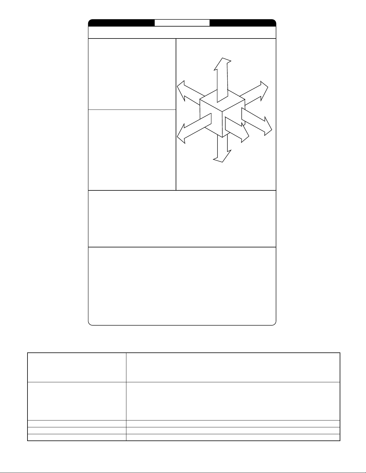
MINIMUM INCHES CLEARANCE TO COMBUSTIBLE CONSTRUCTION
DISTANCE MINIMALE EN POUCES AUX CONSTRUCTIONS COMBUSTIBLES
This forced air furnace is equipped for use with
natural gas at altitudes 0-10,000 ft (0-3,050m).
An accessory kit, supplied by the
manufacturer,shall be used to convert to propane
gas use or may be required for some natural gas
applications.
This furnace is for indoor installation in a
building constructed on site.
This furnace may be installed on combustible
flooring in alcove or closet at minimum clearance
as indicated by the diagram from combustible
material .
This furnace may be used with a Type B-1 Vent
and may be vented in common with other gasfired appliances.
Cette fournaise à air pulsé est équipée
pour utilisation avec gaz naturel et altitudes
comprises entre 0-3,050m (0-10,000 pi).
Utiliser une trousse de conversion, fournie par
le fabricant, pour passer au gaz propane ou pour
certaines installations au gaz naturel.
Cette fournaise est prévue pour être
installée dans un bâtiment construit sur place.
Cette fournaise peut être installée sur
un plancher combustible dans une alcôve ou
dans un garde-robe en respectant le minimum
d'espace libre des matériaux combustibles, tel
qu'indiqué sur le diagramme..
Cette fournaise peut être util isée avec un
conduit d´évacuation de Type B-1 ou connectée
au conduit commun d´autres appareils à gaz..
This furnace is approved for UPFLOW, DOWNFLOW, and
HORIZONTAL install ations.
Cette fournaise est approuvée pour l´installation HORIZONTALE
et la circulation d´air VERS LE HAUT et VERS LE BAS.
1"
Clearance arrows
do not change with
furnace orientati on.
0"
B
A
A
C
R
K
R
I
È
R
E
E
D
I
S
É
T
Ô
C
0"
*
Vent Clearance to combustibles:
For Single Wall vents 6 inches (6 po).
For Type B-1 vent type 1 inch (1 po).
Dégagement de l´évent avec combustibles:
Pour conduit d´évacuation à paroi simple 6 po (6 inches).
Pour conduit d´évacuation de Type B-1 1 po (1 inch).
Les fléches de dégagement
ne changent pas avec
l´orientation de la fournaise.
TOP / PLE NUM
DESSUS / CHAMBRE D'AIR
E
C
E
A
S
N
I
A
R
U
N
F
R
U
T
FO
N
O
T
R
N
F
A
V
A
F
R
O
A
N
V
T
A
N
T
3"
DESSOUS
"
Clearance in inches
Dégagement (po).
BOTTOM
0
†
S
E
N
MIN
Ø
MINIMUM INCHES CLEARANCE TO COMBUSTIBLE CONSTRUCTION
DOWNFLOW POSITIONS:
Installation on non-combustible floors only.
†
For Installation on combustible flooring only when installed on special base, Part No. KGASB0201ALL,
Coil Assembly, Part No. CD5 or CK5, or Coil Casing, Part No. KCAKC.
18 inches front clearance required for alcove.
Ø
Indicates supply or return sides when furnace is in the horizontal position. Line contact only permissible
*
between lines formed by intersections of the Top and two Sides of the furnace jacket, and building joists,
studs or framing.
DÉGAGEMENT MINIMUM EN POUCES AVEC ÉLÉMENTS
DE CONSTRUCTION COMBUSTIBLES
POUR LA POSITION COURANT DESCENDANT:
Pour l ´installation sur plancher non combustible seulement.
†
Pour l´installation sur un plancher combustible seulement quand on utilise la base spéciale, pièce
o
n KGASB0201ALL, l´ensemble serpentin, pièce n CD5 ou CK5, ou l e carter de serpenti n, pièce
o
n KCAKC.
Dans une alcôve, on doit maintenir un dégagement à l´avant de 18 po (450 mm).
Ø
La position indiquée concerne le côté d´entrée ou de retour quand la fournaise est dans la
*
position horizontale.
Le contact n´est permis qu´entre les lignes formées par les intersections du dessus et des
deux côtés de la chemise de la fournaise et les solives, montant sous cadre de charpente.
o
327590-101 REV. B
0"
E
D
*
I
È
T
Ô
C
S
E
R
V
I
T
R
C
E
E
T
I
E
N
30"
MIN
CONTROLS-THERMOSTATS AND ZONING
Auto Changeover, oF/oC, 1-Stage Heat/1-Stage Cool - TSTATBBNAC01-B
Auto Changeover, oF/oC, 2-Stage Heat/1-Stage Cool - TSTATBBNHP01-B
THERMOSTAT- NON-PROGRAMMABLE
THERMOSTAT- PROGRAMMABLE
Auto Changeover, 7-Day Programmable, oF/oC, 1-Stage Heat/1-Stage Cool - TSTATBBPAC01-B
Auto Changeover, 7-Day Programmable, oF/oC, 2-Stage Heat/1-Stage Cool - TSTATBBPHP01-B
Auto Changeover, 7-Day Programmable, oF/oC, 2-Stage Heat/2-Stage Cool - TSTATBBP2S01-B
Thermidistat Control - Non-Programmable/Programmable Thermostat - TSTATBBPRH01-B *
with Humidity Control (For use in Dual Fuel, AC, HP, and 2S applications. Includes Outdoor Air
Auto Changeover, oF/oC, 2-Stage Heat/2-Stage Cool - TSTATBBN2S01-B
Air Conditioner, 1-Stage Heat/1-Stage Cool, Manual Changeover, oF/oC - TSTATBBBAC01
Heat Pump, 2-Stage Heat/1-Stage Cool, Manual Changeover, oF/oC - TSTATBBBHP01
Dual Fuel Thermostat, includes Outdoor Air Temperature Sensor - TSTATBBPDF01-B
in AC Mode, 3-Stage Heat/2-Stage Cool in HP Mode
in AC Mode, 3-Stage Heat/2-Stage Cool in HP Mode
Temperature Sensor.)
ZONING- 2-ZONE ZONEBB2KIT01-B, ZONEKIT2ZBDP
ZONING- 4-ZONE ZONEBB4KIT01-B
ZONING- 8-ZONE ZONEBB8KIT01-B
* Do not use in zoning heat pump applications.
-3-
*
*
Page 4
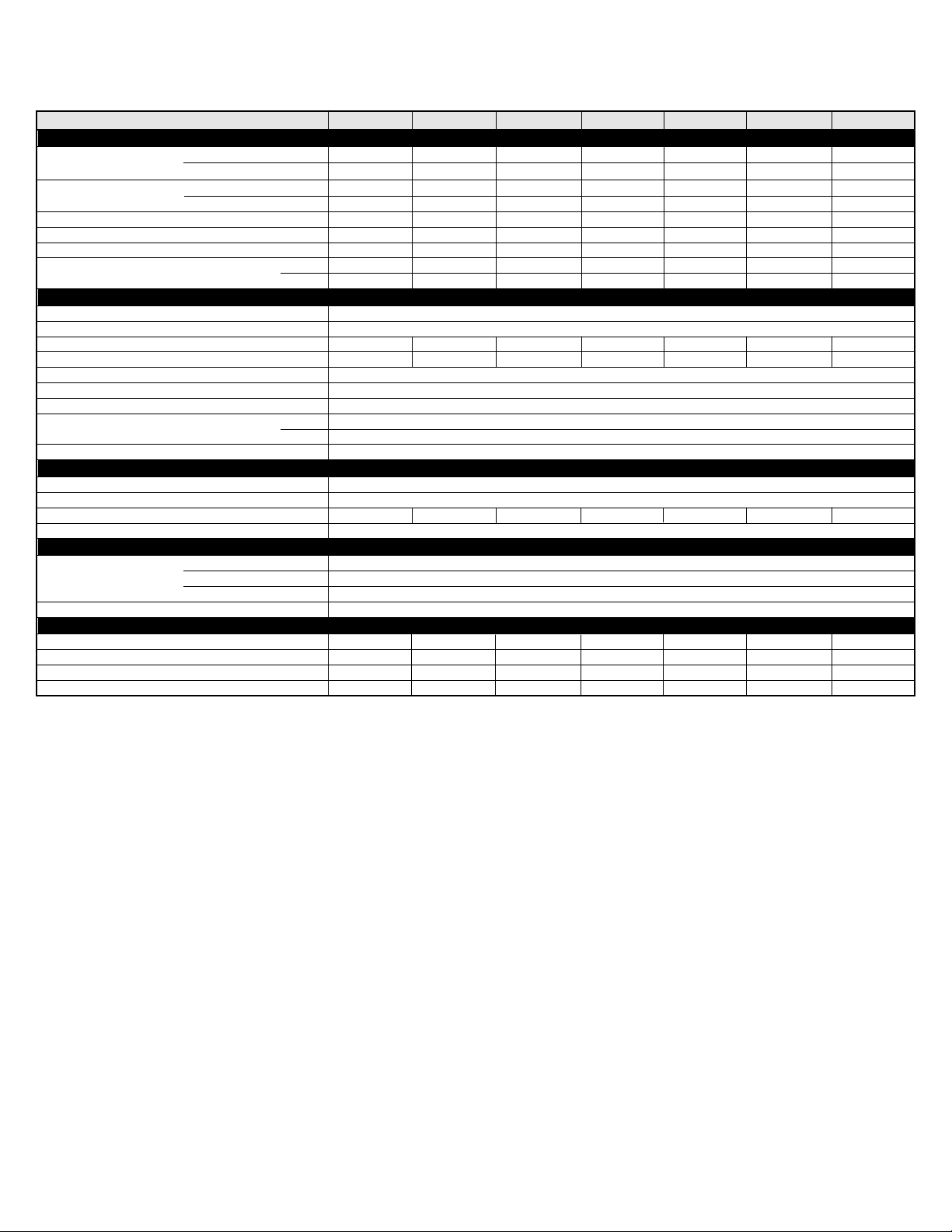
SPECIFICATIONS
UNIT SIZE
RATINGS AND PERFORMANCE
Input Btuh
Nonweatherized ICS
Output Capacity (Btuh)
Nonweatherized ICS
AFUE
Certified Temperature Rise Range oF
Certified External Static Pressure Heat/Cool
Airflow CFM ‡
ELECTRICAL
Unit Volts-Hertz-Phase 115-60-1
Operating Voltage Range Min-Max 104-127
Maximum Unit Amps
Maximum Wire Length (Measured 1 Way in Ft)
Minimum Wire Size 14
Maximum Fuse or Ckt Bkr Size (Amps)** 15
Transformer (24v) 40va
External Control Heating 12va
Power Available Cooling 35va
Air Conditioning Blower Relay Standard
CONTROLS
Limit Control SPST
Heating Blower Control Solid-State Time Operation
Burners (Monoport)
Gas Connection Size 1/2-in. NPT
GAS CONTROLS
Gas Valve (Redundant)
Ignition Device Hot Surface
BLOWER DATA
Direct-Drive Motor HP (PSC)
Motor Full Load Amps
RPM (Nominal)-Speeds
Blower Wheel Diameter x Width (In.)
* Gas input ratings are certified for elevations to 2000 ft. For elevations above 2000 ft, reduce ratings 4 percent for each 1000 ft above sea level. Refer to National
*
311JAV Upflow; all 311AAV
311JAVDownflow/Horizontal
†
311JAV Upflow; all 311AAV
311JAVDownflow/Horizontal
†
Heating
Cooling
Min Inlet Pressure (In. wc) 4.5 (Natural Gas)
Max Inlet Pressure (In. wc) 13.6 (Natural Gas)
Fuel Gas Code Table F4 or furnace Installation Instructions. In Canada, derate the unit 10 percent for elevations 2000 ft to 4500 ft above sea level.
024045
44,000
42,000
35,000
34,000
80.0
30-60
0.10/0.50
920
845
5.6
47
2
1/5
2.9
1075-3
10 x 6
036045
44,000
42,000
36,000
34,000
80.0
20-50
0.10/0.50
1250
1160
7.0
39
2
1/3
5.2
1075-4
10 x 6
024070
66,000
63,000
53,000
51,000
80.0
40-70
0.12/0.50
720
900
5.0
52
3
1/5
2.9
1075-4
10 x 6
036070
66,000
63,000
54,000
51,000
80.0
30-60
0.12/0.50
1195
1200
6.7
40
3
White Rodgers
1/3
5.2
1075-4
10 x 6
048070
66,000
63,000
53,000
51,000
80.0
25-55
0.12/0.50
1450
1530
9.4
29
3
1/2
5.2
1075-4
11 x 8
042090
88,000
84,000
71,000
68,000
80.0
40-70
0.15/0.50
1375
1385
8.1
34
4
1/3
5.2
1075-4
10 x 8
048090
88,000
84,000
71,000
68,000
80.0
30-60
0.15/0.50
1505
1720
9.8
28
1/2
7.9
1075-4
10 x 10
** Time-delay type is recommended.
†
Capacity in accordance with U.S. Government DOE test procedures.
‡
Airflow shown is for bottom only return-air supply for the as-shipped speed tap. For air delivery above 1800 CFM, see Air Delivery table for other options. A filter
is required for each return-
ICS-Isolated Combustion System
N/A-Not Applicable
air supply. An airflow reduction of up to 7% may occur when using the factory-specified 4-5/16-inch wide, high efficiency media filter.
4
-4-
Page 5

SPECIFICATIONS
UNIT SIZE
RATINGS AND PERFORMANCE
Input Btuh
Nonweatherized ICS
Output Capacity (Btuh)
Nonweatherized ICS
AFUE
Certified Temperature Rise Range oF
Certified External Static Pressure Heat/Cool
Airflow CFM ‡
ELECTRICAL
Unit Volts-Hertz-Phase 115-60-1
Operating Voltage Range Min-Max 104-127
Maximum Unit Amps
Maximum Wire Length (Measured 1 Way in Ft)
Minimum Wire Size 14
Maximum Fuse or Ckt Bkr Size (Amps)** 15
Transformer (24v) 40va
External Control Heating 12va
Power Available Cooling 35va
Air Conditioning Blower Relay Standard
CONTROLS
Limit Control SPST
Heating Blower Control Solid-State Time Operation
Burners (Monoport)
Gas Connection Size 1/2-in. NPT
GAS CONTROLS
Gas Valve (Redundant)
Ignition Device Hot Surface
BLOWER DATA
Direct-Drive Motor HP (PSC)
Motor Full Load Amps
RPM (Nominal)-Speeds
Blower Wheel Diameter x Width (In.)
* Gas input ratings are certified for elevations to 2000 ft. For elevations above 2000 ft, reduce ratings 4 percent for each 1000 ft above sea level. Refer to National
Fuel Gas Code Table F4 or furnace Installation Instructions. In Canada, derate the unit 10 percent for elevations 2000 ft to 4500 ft above sea level.
*
311JAV Upflow; all 311AAV
311JAVDownflow/Horizontal
†
311JAV Upflow; all 311AAV
311JAVDownflow/Horizontal
†
Heating
Cooling
Min Inlet Pressure (In. wc) 4.5 (Natural Gas)
Max Inlet Pressure (In. wc) 13.6 (Natural Gas)
060090
88,000
84,000
71,000
68,000
80.0
25-55
0.15/0.50
1990
2025
13.6
32
12
20
4
3/4
11.1
1075-4
11 x 11
036110
110,000
105,000
89,000
85,000
80.0
50-80
0.20/0.50
1335
1355
8.1
34
5
1/3
5.2
1075-4
10 x 8
048110
110,000
105,000
89,000
85,000
80.0
40-70
0.20/0.50
1515
1680
10.0
28
5
1/2
7.9
1075-4
10 x 10
066110
110,000
105,000
89,000
85,000
80.0
30-60
0.20/0.80
1900
2220
13.6
32
12
20
5
White Rodgers
3/4
11.1
1075-4
11 x 11
048135
132,000
126,000
107,000
102,000
80.0
50-80
0.20/0.50
1525
1710
10.0
28
14
15
6
1/2
7.9
1075-4
10 x10
066135
132,000
126,000
107,000
102,000
80.0
40-70
0.20/0.50
1850
2110
14.4
30
6
3/4
11.1
1075-4
11 x 11
060155
154,000
147,000
125,000
119,000
80.0
45-75
0.20/0.50
1790
2230
15.0
12
20
3/4
11.1
1075-4
11 x 11
** Time-delay type is recommended.
†
Capacity in accordance with U.S. Government DOE test procedures.
‡
Airflow shown is for bottom only return-air supply for the as-shipped speed tap. For air delivery above 1800 CFM, see Air Delivery table for other options. A filter
is required for each return-
ICS-Isolated Combustion System
N/A-Not Applicable
air supply. An airflow reduction of up to 7% may occur when using the factory-specified 4-5/16-inch wide, high efficiency media filter.
29
7
-5-
Page 6

SEE NOTES: 1,2,4,7,8,9
UPFLOW
A02058
SEE NOTES: 1,2,3,4,7,8,9
UPFLOW
A02059
SEE NOTES: 1,2,4,5,7,8,9
DOWNFLOW
A02061
SEE NOTES:1,2,3,4,5,7,8,9
DOWNFLOW
A02060
SEE NOTES: 1,2,3,4,5,7,8,9
DOWNFLOW
A02063
SEE NOTES: 1,2,4,5,6,7,8,9
DOWNFLOW
Venting Notes
1. For common vent, vent connector sizing and vent material: United States, latest edition of the National Fuel
Gas Code (NFGC), ANSI Z223.1/NFPA 54. In Canada, latest edition of the National Standards of Canada,
Natural Gas and Propane Installation Code (NSCNGPIC), CSA B149.1-00.
2. Immediately increase to 5-inch vent connector outside furnace casing when 5-inch vent connector required,
refer to Note 1.
3. Side outlet vent for upflow and downflow installations must use Type B vent immediately after exiting the
furnace, except when KGAVG0101DFG is used in downflow position.
4. Type B vent where required, refer to Note 1.
5. 4" single wall vent must be used inside furnace casing and the KGAVG0101DFG Downflow Vent Guard Kit.
6. Accessory Downflow Vent Guard Kit, KGAVG0101DFG required in downflow installations with bottom vent
configuration.
7. Chimney Adapter Kit required for exterior masonry chimney applications. Refer to Chimney Adapter Kit,
KGACA02014FC and KGACA02015FC for sizing and complete application details.
8. Secure vent connector to furnace elbow with (2) corrosion-resistant sheet metal screws, space approximately
o
apart.
180
9. Secure all other single wall vent connector joints with (3) corrosion-resistant screws spaced approximately
o
apart. Secure Type B vent connectors per vent connector manufacturer's recommendations.
120
A02062
-6-
Page 7

SEE NOTES: 1,2,4,5,7,8,9
HORIZONTAL RIGHT
A02068
SEE NOTES: 1,2,4,7,8,9
HORIZONTAL RIGHT
SEE NOTES: 1,2,4,5,7,8,9
HORIZONTAL RIGHT
A02070
A02069
SEE NOTES: 1,2,4,7,8,9
HORIZONTAL LEFT
SEE NOTES: 1,2,4,5,7,8,9
HORIZONTAL LEFT
A02066
A02064
SEE NOTES: 1,2,4,5,7,8,9
HORIZONTAL LEFT
SEE NOTES: 1,2,4,5,7,8,9
HORIZONTAL LEFT
A02065
A02067
-7-
Page 8

FACTORY-AUTHORIZED DEALER-INSTALLED ACCESSORIES
DESCRIPTION PART NO.
024045
036045
024070
036070
048070
042090
048090
060090
036110
048110
066110
048135
066135
060155
EZ Flex Media Filter with end
caps - 16 i n. (9 pack)
EZ Flex Media Filter with end
caps - 20 i n. (9 pack)
EZ Flex Media Filter with end
caps - 24 i n. (6 pack)
Replacement EZ Flex Filter - 16
in. (10 pack)
Replacement EZ Flex Filter - 20
in. (10 pack)
Replacement EZ Flex Filter - 24
in. (10 pack)
Unframed filter, one inch - 16x25 KGAWF1301UFR
Unframed filter, one inch 20x25
Unframed filter, one inch 24x25
Twinning Kit KGATW0601HSI x x x x x x x x x x x x x x
Combustible Floor Base (not
required when evaporator coil
case is used)
Downflow Vent Guard (not
required when vent is routed
through cabinet)
Vent Extension Kit (may be used
when vent is routed through
cabinet in downflow)
Chimney Adapter Kit - 4 i nch
vent
Chimney Adapter Kit - 5 i nch
vent
Natural-to-Propane Gas
Conversion Kit (Single Kit)
Propane-to-Natural Gas
Conversion Kit (Single Kit)
EXPXXUNV0016
EXPXXUNV0020
EXPXXUNV0024
EXPXXFIL0016
EXPXXFIL0020
EXPXXFIL0024
KGAWF1306UFR (6-pack)
KGAWF1401UFR
KGAWF1406UFR (6 pack)
KGAWF1501UFR
KGAWF1506UFR (6 pack)
KGASB0201ALL
KGAVG0101DFG
KGAVE0101DNH
KGACA02014FC
KGACA02015FC
KGANP2901ALL
*
KGAPN2301ALL
x x x x x x x
x x x x x x x
x x x x x x
x
x x x x x x x x x x x x x x
x x x x x x x x x x x x x x
x x x x
x
x x x x x x x x x x x
x x x x x x x x x x x x x x
x x x x x x x x x x x x x x
x x x x x
x x
x x x x x
x x
s s s s s s s
x x x x x
xx
x x x x x x x x x
x x x
Gas Orifice Kit (Qty 50) Size 42 KGAHA0150N42
Gas Orifice Kit (Qty 50) Size 43 KGAHA0250N43
Gas Orifice Kit (Qty 50) Size 44 KGAHA0350N44
Gas Orifice Kit (Qty 50) Size 45 KGAHA0450N45
Gas Orifice Kit (Qty 50) Size 46 KGAHA0550N46
Gas Orifice Kit (Qty 50) Size 47 KGAHA1550N47
Gas Orifice Kit (Qty 50) Size 48 KGAHA1650N48
See Installation Instructions for model,
altitude, and heat value usages.
Gas Orifice Kit (Qty 50) Size 54 KGAHA0650P54
Gas Orifice Kit (Qty 50) Size 55 KGAHA0750P55
Gas Orifice Kit (Qty 50) Size 56 KGAHA0850P56
Gas Orifice Kit (Qty 50) 1.25 mm KGAHA5750125
Gas Orifice Kit (Qty 50) 1.30 mm KGAHA5750130
* Factory-authorized and field installed. Gas conversion kits are A.G.A./C.G.A. recognized.
s
16x25 filters suitable for side return on all furnace sizes.
-8-
Page 9

AIR DELIVERY-CFM (With Filter)*
UNIT SIZE
024045
036045
024070
036070
048070
042090
048090
060090
036110
048110
* A filter is required for each return-air supply. Airflow performance includes 1" washable filter media such as contained in factory-authorized accessory filter rack.
To determine airflow performance without this filter, assume an additional .1 available external static pressure.
-Indicates unstable operating conditions.
RETURN-AIR
SUPPLY
Bottom
or
Side(s) Med-Low
Bottom
or
Side(s)
Bottom
or
Side(s)
Bottom
or
Side(s)
Bottom
or
Side(s)
Bottom
or
Side(s)
Bottom
or
Side(s)
Bottom
Only
Both Sides or
1 Side & Bottom
1 Side Only
Bottom
or
Side(s)
Bottom
or
Side(s)
SPEED
High
Med-High
High
Med-High
Med-Low
Low
High
Med-High
Med-Low
High
Med-High
Med-Low
Low
High
Med-High
Med-Low
Low
High
Med-High
Med-Low
Low
High
Med-High
Med-Low
Low
High
Med-High
Med-Low
Low
High
Med-High
Med-Low
Low
High
Med-High
Med-Low
Low
High
Med-High
Med-Low
Low
High
Med-High
Med-Low
Low
0.1 0.2
1085
920
820
1440
1360
1250
1085 1055
1030
835
725
1425
1320
1200
1040
1805
1630
1460
1275
1650
1515
1385
1205
2060
1790
1505
1225
2405
2225
2020
1810
2530
2285
1995
1770
2475
2260
1950
1730
1625
1510
1360
1195
2035
1745
1530
1270 1265
1035
875
775
1375
1300
1210
1010
815
700
1375
1280
1175
1030
1740
1585
1420
1250
1600
1485
1360
1180
1985
1765
1505
1225 1220
2310
2155
1955
1765 1715 1645
2450
2215
1945
1740
2395
2190
1910
1695
1575
1470
1335
1180
1965
1710
1515
0.3 0.4
1305
1240
1160
1035 990 945 885
1320
1240
1145
1010
1670
1530
1385
1225 1195
1535
1440
1320
1160
1915
1715
1480
2220
2080
1880
2365
2150
1900
1700
2300
2110
1855
1650 1600
1515
1415
1295
1155
1880
1650
1470
1235 1195
EXTERNAL STATIC PRESSURE (In. wc)
975
830
730
980
790
675
915
770
680
1240
1175
1100
945
760
645
1265
1205
1105
985
1600
1470
1325
1465
1380
1260
1120
1820
1645
1440
1195
2130
1995
1805
2270
2075
1840
1645
2200
2035
1795
1445
1355
1250
1115 1065
1790
1560
1400
1160
1115
1040
1200
1140
1050
1530
1405
1280
1155
1385
1300
1195
1065
1720
1560
1375
1155
2025
1895
1730
1565
2165
1985
1770
1575
2090
1940
1730
1535 1470
1355
1285
1180
1680
1450
1310
1130
0.5
845
710
620
900
720
600
945
0.6
770
640
555
1070
1040
965
845
675
555
1125
1075
990
895
1445
1330
1220
1105 1050
1285
1220
1120
1005
1610
1470
1300
1085
1920
1785
1630
1480
2065
1890
1685
1505
1985
1845
1650 1555
1260
1185
1100
980 860 740
1495
1340
1215
1055
0.7
675
555
470
975
950
885
810
775
610
475
1035
995
920
845
1360
1255
1155
1175
1115
1025
925 810
1490
1345
1190
985
1790
1675
1535
1390
1940
1780
1600
1415
1865
1735
1385
1165
1070
985
1365
1205
1095
970 875
1340
0.8
565
440
360
870
850
790
715
680
490
390
940
905
840
765
1280
1170
1080
980
1055
990
915
1195
1045
870
1660
1565
1420
1280 1145
1805
1660
1480
1325
1730
1620
1445
1285 1165 1000
990
890
810
1215
1090
990
0.9
390
250
190
730
725
670
595
490
375
300
830
790
725
655
1180
1080
995
910
895
830
710
630
1135
1010
890
735
1530
1420
1275
1670
1525
1350
1190
1585
1475
1310 1150
785
725
670
605
1075
955
830
720
1.0
195
---
560
575
520
435
335
265
---
655
620
555
505
1075
990
910
835
645
600
565
510
925
820
740
620
1350
1260
1135
1005
1505
1360
1180
1040
1425
1325
595
530
475
410
875
750
670
600
---
-9-
Page 10

AIR DELIVERY-CFM (With Filter)*
UNIT SIZE
066110
048135
066135
060155
* A filter is required for each return-air supply. Airflow performance includes 1" washable filter media such as contained in factory-authorized accessory filter rack.
To determine airflow performance without this filter, assume an additional .1 available external static pressure.
-Indicates unstable operating conditions.
RETURN-AIR
SUPPLY
Bottom
Only
Both Sides or
1 Side & Bottom
1 Side Only
Bottom
or
Side(s)
Bottom
Only
Both Sides or
1 Side & Bottom
1 Side Only
Bottom
Only
Both Sides or
1 Side & Bottom
1 Side Only
SPEED
High
Med-High
Med-Low
Low
High
Med-High
Med-Low
Low
High
Med-High
Med-Low
Low
High
Med-High
Med-Low
Low
High
Med-High
Med-Low
Low
High
Med-High
Med-Low
Low
High
Med-High
Med-Low
Low
High
Med-High
Med-Low
Low
High
Med-High
High
Med-High
0.1 0.2
2530
2230
1920
1640
--2235
1920
1640
2540
2125
1790
1515 1535
2090
1790
1545
1325 1320
2485
2195
1880
1640 1635 1615 1585
---
2180
1880
1640 1635
--2135
1880
1640
2465
2115
1800
1570 1565
---
2155
--2140
2470
2205
1900
1650
--2200
1900
1650
2495
2120
1795
2010
1755
1525
2400
2150
1850
---
2145
1850
---
2085
1850
1620
2430
2105
1790
---
2135
---
2095
0.3 0.4
2400
2165
1880
1635 1610 1575
2415
2155
1880
1635 1610 1575
2430
2105
1790
1535
1930
1705
1500
1295
2310
2090
1820
2385
2060
1820
1615
2245
2035
1820
1580
2375
2075
1770
1550
2375
2095
2260
2040
EXTERNAL STATIC PRESSURE (In. wc)
0.5
2320
2110
1845
2350
2100
1845
2355
2060
1765
1522
1835
1640
1450
1265 1210 1150
2215
2000
1780
2305
2010
1780
1585
2155
1975
1780
1540
2305
2030
1735
1525
2285
2040
2180
1975
2220
2035
1795
2250
2040
1795
2265
2010
1720
1490
1710
1550
1380
2110
1920
1715
1530
2195
1945
1715
1530
2055
1895
1715 1635 1540 1415 1290 1160
1485
2230
1980
1695
1495 1445
2200
1975
2085
1890
0.6
2115
1950
1730
1520 1455
2145
1955
1730
1520 1455 1375 1285
2175
1940
1650 1585
1445
1590
1465
1315
2000
1825
1635
1465
2085
1865
1635
1465
1940
1795
1410
2110
1910
1640
2105
1895
1975
1810
0.7
2000
1855
1650
2015
1850
1650
2065
1840
1390
1470
1360
1215
995
1880
1720
1540
1370
1960
1765
1540
1370
1825
1685
1330
2000
1830
1570
1370
1995
1790
1865
1705
0.8
1865
1740
1555
1375
1875
1740
1555
1935
1730
1500
1315
1335
1210
1005
865 745
1725
1565
1415
1255
1825
1660
1415
1255
1695
1565
1220
1865
1725
1465
1270
1870
1685
1740
1595
0.9
1730
1615
1460
1285
1715
1595
1460
1785
1615
1390 1280
1225
1025
945
855
1535
1405
1290
1150 1040
1670
1515
1290
1150
1555
1445
1080
1725
1590
1345
1175 1070
1730
1550
1605
1480
1.0
1590
1485
1340
1170
1560
1470
1340
1170
1650
1485
1120
835
785
670
540
1355
1255
1160
1465
1325
1160
1040
1385
1265
1545
1425
1225
1570
1400
1455
1325
960
-10-
Page 11

-11-
Page 12

SPECIFICATIONS SUBJECT TO CHANGE WITHOUT NOTICE
UNIT MUST BE INSTALLED IN ACCORDANCE
WITH INSTALLATION INSTRUCTIONS
Cancels: 311A.45.1
© 2003 Bryant Heating & Cooling Systems, 7310 W. Morris St. Indpls., IN 46231 PRINTED IN U.S.A. Catalog No. 5231-102 02-03
 Loading...