

285B
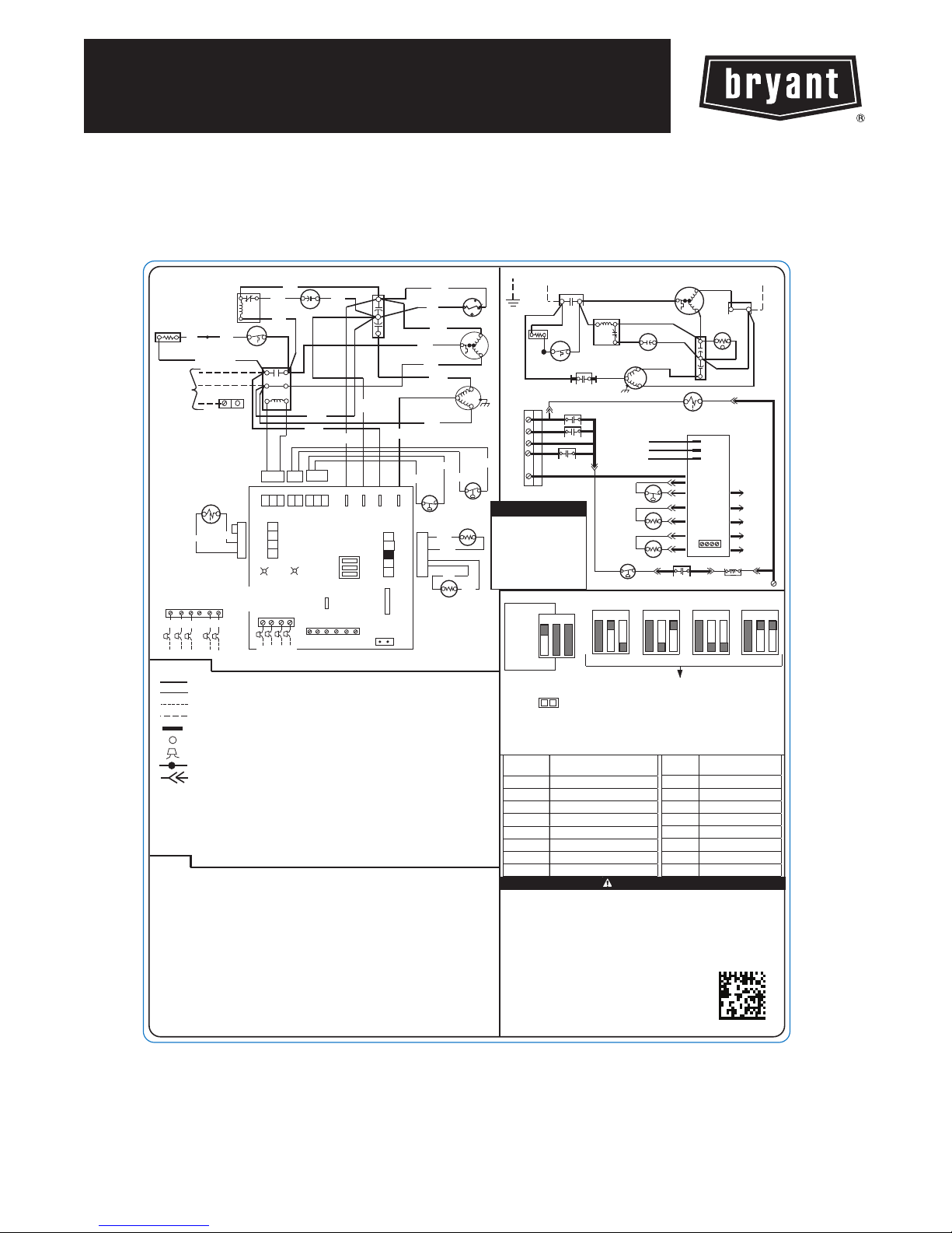
EVOLUTIONR15 HEAT PUMP
WITH PURONr REFRIGERANT
1--1/2 TO 5 TONS
Wiring Diagram
CONNECTION DIAGRAM
BRN
1
2
5
BLK
BLK
*CHS
CONT
11
23
C
YEL / BLU
PL4
CC
13
HP
C
PL1
RVS
COMM
AS PROVIDED
SEE NOTE #12
B
A
YEL
GRN
TO INDOOR UNIT
BLU
21
23
C
BRN / YEL
4
3
2
STATUS
C
WHT
D
RED
*SC
PL3
HPS
12
VIO
1
RC
YEL
YEL
PL2
LPS
2
UTIL
YLSW2
* MAY BE FACTORY OR FIELD INSTALLED
*SR
(NOTE #8)
BLK
or
BLK
RED
*C
H
RED or BLK
L1
208/230 1Ø
L2
POWER
SUPPLY
NON-COMMUNICATING
LEGEND
AUXR
CAP
*CH
*CHS
COMP
NOTES:
1. Compressor and fan motor furnished with inherent thermal protection.
2. To be wired in accordance with national electric code (N.E.C.) And local codes.
3. N.E.C. Class 2, 24 V circuit, min. 40 VA required, 60VA on units installed with LLS.
4. Use copper conductors only from disconnect to units suitable for at least 75ºC (167ºF).
5. Must use thermostat and sub-base as stated in pre-sale literature.
6. If indoor section has a transformer with a grounded secondary, connect the Grounded
side to "C" on the circuit board.
7. If any of the original wire, as supplied, must be replaced, use the same or
Equivalent wire.
8. Check all electrical connections inside control box for tightness.
9. Do not attempt to operate unit until service valves have been opened.
10. Symbols are electrical representation only.
11. When start relay and start capacitor are installed, start thermistor is not used.
12. For communicating control only.
13. In case of non-communicating Indoor system, disconnect factory provided wires
from A, B, C, and D terminals. Using factory provided wires connect to R, C, Y, W2,
and O terminals as required by Installation Instructions. Connect field 24V wires to
factory provided wires, cap or remove unused factory provided wires.
EQUIP GND
RVS
ORG
ORG
OPTIONAL
CONTROL
SEE NOTE #13
RC
CB
BY MANUFACTURER
LS
W2
O
Y
FACTORY POWER WIRING
FACTORY CONTROL WIRING
FIELD CONTROL WIRING
FIELD POWER WIRING
CONDUCTOR ON CIRCUIT BOARD
COMPONENT CONNECTION
FIELD SPLICE
JUNCTION
PLUG RECEPTACLE
AUXILLARY HEAT RELAY
CAPACITOR (DUAL RUN)
CIRCUIT BOARD
CRANKCASE HEATER
CRANKCASE HEATER SWITCH
COMPRESSOR
BLU
VS
DEFROST
TIME
QUIET
SHIFT
CAP
H
C
F
YEL
BLK
YEL/PNK
VR L1 ODF
1
OCT
2
3
OAT
4
5
P1
FORCED
DEFROST
O
CONT
*HPS
LLSR
ODFR
RVSR
CB
CONTACTOR
DEFROST THERMOSTAT
DFT
DEFROST RELAY AND CIRCUITRY
DR
HIGH PRESSURE SWITCH
LOW PRESSURE SWITCH
*LPS
LIQUID LINE SOLENOID RELAY
OUTDOOR AIR THERMISTOR
OAT
OUTDOOR COIL THERMISTOR
OCT
OUTDOOR FAN RELAY
OUTDOOR FAN
ODF
REVERSING VALVE SOLENOID
RVS
REVERSING VALVE SOLENOID
RELAY START CAPACITOR
*SC
START RELAY
*SR
START THERMISTOR
*ST
YEL
BLU
BLK
YEL
BRN
YEL
YEL/PNK
* LPS
PL5
SCHEMATIC DIAGRAM (LADDER FORM)
BLU
*ST
t
+
S
C
R
COMP
ODF
BLU/PNK
BLU/PNK
* HPS
OCT
BRN
BRN
BLK
BLK
OAT
L1
CONT
21
GND
11
* CH
O
W2
R
LS
Y
* CHS
LLSR
L1
RVSR
AUXR
ODFR
ODF
* SR
2
5
1
NOTE
* HPS
DIP SWITCH SETTINGS
OFF
(DEFAULT)
123
QUIET
SHFT
ON
SPEED
UP
1) MOMENTARILY SHORT PINS AND RELEASE TO BYPASS COMPRESSOR OFF DELAY.
2) SHORT FOR 5+ SEC. AND RELEASE FOR FORCED DEFROST.
3) PERMANENT SHORT WILL BE IGNORED.
DEFROST WILL TERMINATE IN 30 SEC. IF DFT OPEN.
DEFROST WILL TERMINATE NORMALLY IF DFT IS CLOSED.
FLASH
CODE
On, No Flash Standby
1, Pause Normal Operation
16 System Communications Failure
31 High Pressure Switch
32 Low Pressure Switch
45 Control Fault
46 Brown out (24V)
53 Outside Temp Sensor
1. Compressor damage may occur if system is over charged.
2. This unit is factory charged with R-410A in accordance with the amount shown
on the rating plate. The charge is adequate for most systems using matched
coils and tubing not over 15 feet long. Check refrigerant charge for maximum
efficiency. See Product Data Literature for required Indoor air Flow Rates and
for use of line lengths over 15 feet.
3. Relieve pressure and recover all refrigerant before system repair or final
disposal. Use all service ports and open all flow-control devices, including
solenoid valves.
4. Never vent refrigerant to atmosphere. Use approved
recovery equipment.
30 M IN UT ES
123
30
JUMPERED TEST PINS (USE METAL OBJECT), FIELD SPEED-UP CYCLE
FAULT DEFINITION
EQUIP
THIS DEFROST CONTROL
BOARD CONTAINS A FIVE
MINUTE SHORT CYCLE
PROTECTOR. A FIVE
MINUTE DELAY WILL
OCCUR BETWEEN
COMPRESSOR OFF/ON
CYCLES.
COMP
R
C
*SC
ODF
RVS
L1
VS
VR
LPS
OAT
OCT
CB
K4
60 M IN UT ES
123 123 123
60
OR
FIELD SELECTABLE OPTIONS FOR TIME PERIOD
BETWEEN DEFROST CYCLES (MINUTES)
CAUTION
OR OR
FLASH
CODE
55 Coil Temp Sensor
56 Thermistor Range Error
72 Thermal Cutout
73 Contactor Shorted
74 No 230V at Compressor
82 Thermal lockout
83 Low pressure lockout
84 High pressure lockout
CONT
S
23
CAP
+t°
H
* ST
C
F
C
L
O
G
OUTPUT
I
C
INPUT
SEE NOTE #12
C
B
A
D
CONT
(D EFAU LT )
90 M INUT ES
90
FAULT DEFINITION
ODFR
RVSR
AUXR
LLSR
K4
120 MINUTES
L2
23
C
120
339109-101 REV. A
Fig. 1 – Wiring Diagram — Model size 1.5 -- 5 tons, 208/230--1

EBryant Heating & Cooling Systems 7310 W. Morris St. Indianapolis, IN 46231 Edition Date: 09/12
Manufacturer reserves the right to discontinue, or change at any time, specifications or designs without notice and without i ncurring obligations.
Catalog No. WD285B--- 01
Replaces: New
2
 Loading...