

Bryant 264A, 265A, 285B Installation Instructions Manual
264A / 265A
PREFERRED SERIES HEA T PUMP
WITH PURON REFRIGERANT
SIZES 018 TO 060
1--1/2 TO 5 NOMINAL TONS
Installation Instructions
SAFETY CONSIDERATIONS
Improper installation, adjustment, alteration, service,
maintenance, or use can cause explosion, fire, electrical shock, or
other conditions which may cause death, personal injury, or
property damage. Consult a qualified installer, service agency, or
your distributor or branch for information or assistance. The
qualified installer or agency must use factory--authorized kits or
accessories when modifying this product. Refer to the individual
instructions packaged with the kits or accessories when installing.
Follow all safety codes. Wear safety glasses, protective clothing,
and work gloves. Use quenching cloth for brazing operations.
Have fire extinguisher available. Read these instructions
thoroughly and follow all warnings or cautions included in
literature and attached to the unit. Consult local building codes
and National Electrical Code (NEC) for special requirements.
Recognize safety information. This is the safety--alert symbol
When you see this symbol on the unit and in instructions or
manuals, be alert to the potential for personal injury.
Understand these signal words: DANGER, WARNING, and
CAUTION. These words are used with the safety-- alert symbol.
DANGER identifies the most serious hazards which will result in
severe personal injury or death. WARNING signifies hazards
which could result in personal injury or death. CAUTION is
used to identify unsafe practices which may result in minor
personal injury or product and property damage. NOTE is used to
highlight suggestions which will result in enhanced installation,
reliability, or operation.
!
ELECTRICAL SHOCK HAZARD
Failure to follow this warning could result in personal injury
or death.
Before installing, modifying, or servicing system, main
electrical disconnect switch must be in the OFF position.
There may be more than 1 disconnect switch. Lock out and
tag switch with a suitable warning label.
IMPORTANT: Maximum liquid-- line size is 3/8--in. OD for all
residential applications including long line.
IMPORTANT: Always install the factory--supplied liquid--line
filter drier. Obtain replacement filter driers from your distributor
or branch.
WARNING
INSTALLATION RECOMMENDATIONS
NOTE: In some cases noise in the living area has been traced
to gas pulsations from improper installation of equipment.
1. Locate unit away from windows, patios, decks, etc. where
unit operation sound may disturb customer.
2. Ensure that vapor and liquid tube diameters are appropriate for unit capacity.
3. Run refrigerant tubes as directly as possible by avoiding
unnecessary turns and bends.
4. Leave some slack between structure and unit to absorb vibration.
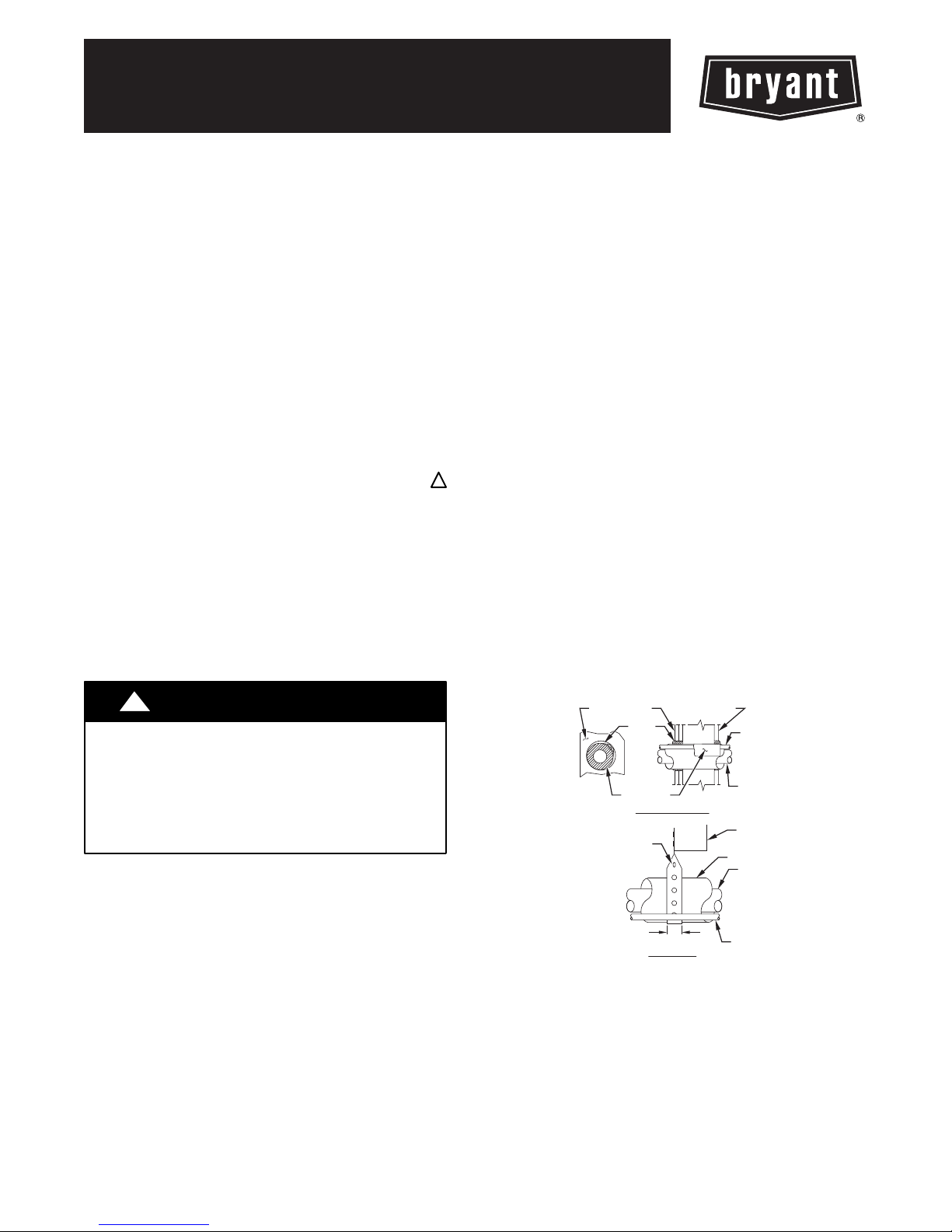
5. When passing refrigerant tubes through the wall, seal
opening with RTV or other pliable silicon--based caulk.
(See Fig. 1.)
!
!
6. Avoid direct tubing contact with water pipes, duct work,
floor joists, wall studs, floors, and walls.
7. Do not suspend refrigerant tubing from joists and studs
with a rigid wire or strap which comes in direct contact
with tubing. (See Fig. 1.)
8. Ensure that tubing insulation is pliable and completely
surrounds vapor tube.
9. When necessary, use hanger straps which are 1 in. (25.4
mm) wide and conform to shape of tubing insulation. (See
Fig. 1.)
10. Isolate hanger straps from insulation by using metal
sleeves bent to conform to shape of insulation.
Avoid contact between tubing and structureNOTE:
OUTDOOR WALL INDOOR WALL
CAULK
INSULATION
THROUGH THE WALL
HANGER STRAP
(AROUND VAPOR
TUBE ONLY)
1″ (25.4 mm)MIN.
SUSPENSION
LIQUID TUBE
VAPOR TUBE
JOIST
INSULATION
VAPOR TUBE
LIQUID TUBE
A94028
Fig. 1 --- Connecting Tubing Installation
When outdoor unit is connected to factory-- approved indoor unit,
outdoor unit contains system refrigerant charge for operation with
ARI rated indoor unit when connected by 15 ft/4.57 m. of
field--supplied or factory accessory tubing. For proper unit
operation, check refrigerant charge using charging information
located on control box cover and/or in the Check Charge section
of this instruction.
INSTALLATION
Check Equipment and Job Site
Unpack
Move to final location. Remove carton taking care not to damage
unit.
Inspect Equipment
File claim with shipping company prior to installation if shipment
is damaged or incomplete. Locate unit rating plate on unit corner
panel. It contains information needed to properly install unit.
Check rating plate to be sure unit matches job specifications.
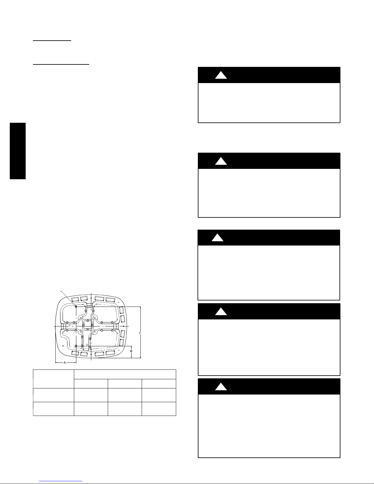
Install on a Solid, Level Mounting Pad
If conditions or local codes require the unit be attached to pad,
tiedown bolts should be used and fastened through knockouts
provided in unit base pan. Refer to unit mounting pattern in
Fig. 2 to determine base pan size and knockout hole location.
For hurricane tie downs, contact distributor for details and PE
Certification (Professional Engineer), if required.
On rooftop applications, mount on level platform or frame. Place
unit above a load--bearing wall and isolate unit and tubing set
from structure. Arrange supporting members to adequately
264A / 265A
support unit and minimize transmission of vibration to building.
Consult local codes governing rooftop applications.
Roof mounted units exposed to winds above 5 mph may require
wind baffles. Consult the Service Manual -- Residential Split
System Air Conditioners and Heat Pumps for wind baffle
construction.
NOTE: Unit must be level to within ±2° (±3/8 in./ft.) per
compressor manufacturer specifications.
Clearance Requirements
When installing, allow sufficient space for airflow clearance,
wiring, refrigerant piping, and service. Allow 30 in. (762 mm)
clearance to service end of unit and 48 in. (1219.2 mm) above
unit. For proper airflow, a 6 in. (152.4 mm) clearance on 1 side of
unit and 12 in. (304.8 mm) on all remaining sides must be
maintained. Maintain a distance of 24 in. (609.6 mm) between
units. Position so water, snow, or ice from roof or eaves cannot
fall directly on unit.
Unit
3/8-- IN. DIA. TIEDOWN KNOCKOUTS
IN BASEPAN (2) PLACES
Operating Ambient
The minimum outdoor operating ambient in cooling mode is
55°F/12.78_C without low ambient cooling enabled, and the
maximum outdoor operating ambient in cooling mode is
125°F/51.67_C. The maximum outdoor operating ambient in
heating mode is 66 °F/18.89_C.
Elevate Unit
!
UNIT OPERATION HAZARD
Failure to follow this caution may result in equipment
damage or improper operation.
Unit must be kept free of an accumulation of water and/or ice
in the basepan.
Elevate unit per local climate and code requirements to provide
clearance above estimated snowfall level and ensure adequate
drainage of unit. If using accessory support feet, use installation
instructions from kit for installation.
!
EQUIPMENT DAMAGE HAZARD
Failure to follow this caution may result in equipment
damage or improper operation.
To prevent damage to the unit, ensure that it is located with
the supports such that the unit is stable in all circumstances
including adverse conditions.
CAUTION
CAUTION
Make Piping Connections
!
PERSONAL INJURY / ENVIRONMENTAL HAZARD
Failure to follow this warning could result in personal injury
or death.
Relieve pressure and recover all refrigerant before system
repair or final unit disposal.
Use all service ports and open all flow--control devices,
including solenoid valves.
WARNING
VIEW
FROM TOP
UNIT BASE PAN
DIMENSIONS
in. (mm)
29--1/2 X 33
(749.3 X 838.2)
36–1/2 X 40
(927.1 X 10¹⁶)
Fig. 2 --- Tiedown Knockout Requirements
On rooftop applications, locate unit at least 6 in. above roof
surface.
TIEDOWN KNOCKOUT LOCATIONS in. (mm)
A B C
10–1/16
(255.6)
9–5/8
(244.5)
5–5/8
(142.9)
6–13/16
(173.0)
23–3/4
(603.3)
28–3/4
(730.3)
A05177
!
UNIT DAMAGE HAZARD
Failure to follow this caution may result in equipment
damage or improper operation.
If ANY refrigerant tubing is buried, provide a 6 in. (152.4
mm) vertical rise at service valve. Refrigerant tubing lengths
up to 36 in.(914.4 mm) may be buried without further
special consideration. Do not bury lines longer than 36 in.
(914.4 mm).
!
UNIT DAMAGE HAZARD
Failure to follow this caution may result in equipment
damage or improper operation.
To prevent damage to unit or service valves, observe the
following:
S Use a brazing shield.
S Wrap service valves with wet cloth or use a heat sink
material.
2
CAUTION
CAUTION
Outdoor units may be connected to indoor section using
accessory tubing package or field-- supplied refrigerant grade
tubing of correct size and condition. For tubing requirements
beyond 80 ft/24.38 m, substantial capacity and performance
losses can occur. Following the recommendations in the Long
Line Guideline for Split--System Air Conditioners and Heat
Pumps will reduce these losses. Refer to Table 1 for accessory
requirements. Refer to Table 2 for field tubing diameters.
If refrigerant tubes or indoor coil are exposed to atmosphere, they
must be evacuated to 500 microns to eliminate contamination and
moisture in the system.
Table 1—Accessory Usage
REQUIRED FOR LOW--- AMBIENT
ACCESSORY
Accumulator Standard Standard Standard
Compressor Start Assist
Capacitor and Relay
Crankcase Heater Ye s
Evaporator Freeze Thermostat
Isolation Relay
Liquid Line Solenoid Valve No
Motor Master Control or
Low Ambient Switch
Support Feet Recommended No Recommended
* For tubing line sets between 80 and 200 ft. (24.38 and 60.96 m) and/or 20 ft. (6.09 m) vertical differential, refer to Residential Split --- System Longline Application Gui deline.
COOLING APPLICATIONS
(Below 55F / 12.8C)
Ye s Ye s No
Ye s
(for non ---Evolution systems only)
Ye s
(for non ---Evolution systems only)
Ye s
(for non ---Evolution systems only)
REQUIRED FOR
LONG LINE APPLICATIONS*
(Over 80 ft. / 24.38 m)
Ye s
No No
No No
See Long ---Line Application
Guideline
No No
REQUIRED FOR
SEA COAST APPLICATIONS
(Within 2 miles / 3.22 km)
No
No
Table 2—Refrigerant Connections and Recommended Liquid and Vapor Tube Diameters (In.)
UNIT SIZE
LIQUID
Connection Diameter Tube Diameter Connection Diameter Rated Tube Diameter
018, 024 3/8 3/8 5/8 5/8
030, 036 3/8 3/8 3/4 3/4
042, 048 3/8 3/8 7/8 7/8
060 3/8 3/8 7/8 1--1/8
Notes:
1. Tube diameters are for total equivalent lengths up to 80 ft. (24.38 m)
2. Do not apply capillary tube or fixed orifice indoor coils to these units.
* For Tubing Set lengths between 80 and 200 ft. (24.38 and 60.96 m) horizontal or 20 ft. (6.10 m) vertical differential (250 ft./ 76.2 m)Total Equivalent Lengt h),
refer to the Longline Guideline --- Air Conditioners and Heat P umps using Puronr Refrigerant.
VA P O R
(up to 80 ft/24.38 m)
264A / 265A
the environmentally sound refrigerant
ISO 9001:2000
REGISTERED
Ready for use in a Hybrid Heatr Duel Fuel system.
3
This produ ct has been desi gned and manuf actured to
meet Energy Star criteria for energy efficiency when
matched with appropriate coil components. However,
proper refr igerant ch arge and proper ai r flow are cr itical
to achieve rated capacity and effi ciency. Installation of
this product should follow all manufacturing refri gerant
charging and air flow instructions. Failure to confirm
proper charge and air flow may reduce energy
efficiency and shorten equipment life.
Outdoor Unit Connected to Factory Approved
T
Indoor Unit
These outdoor units are carefully evaluated and listed with
specific indoor coils for proper system performance.
Install Adapter Tube
1. Remove plastic retainer holding outdoor piston in liquid
service valve.
2. Check outdoor piston size with matching number listed on
unit rating plate.
3. Locate plastic bag taped to unit containing adapter tube.
4. Remove Teflon seal from bag and install on open end of
liquid service valve. (See Fig. 3.)
5. Remove adapter tube from bag and connect threaded nut
to liquid service valve. Tighten nut finger--tight and then
with wrench an additional 1/2 turn (15 ft--lb). DO NOT
OVER TIGHTEN!
TEFLONr SEAL
PISTON
A05227
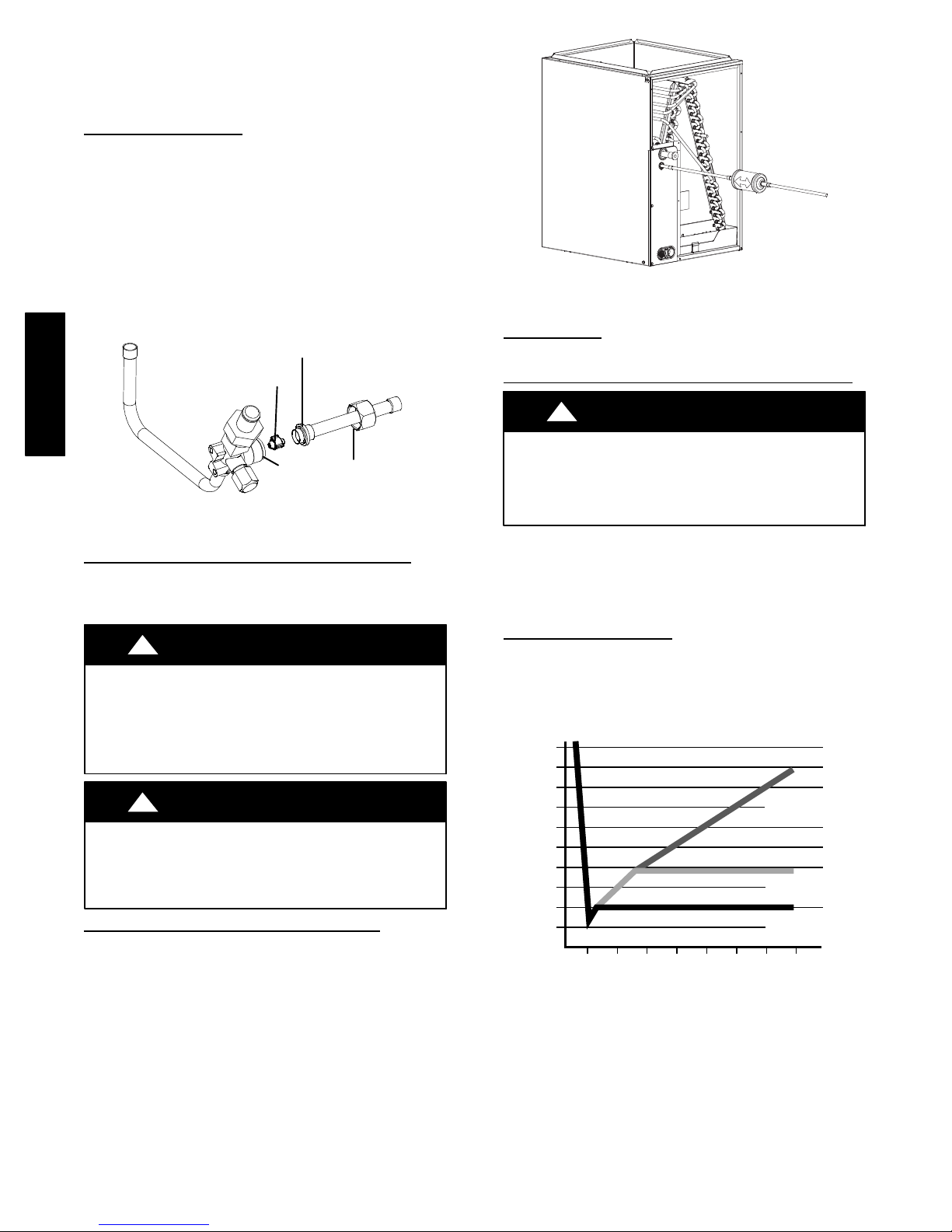
Fig. 4 --- Liquid Line Filter Drier
Leak Testing
Leak test all joints; indoors, outdoors, and refrigerant tubing.
Evacuate Refrigerant Tubing and Indoor Coil
264A / 265A
PISTON
BODY
Fig. 3 --- Liquid Service Valve with Sweat Adapter Tube
SWEAT / FLARE
ADAPTER
Refrigerant Tubing and Sweat Connections
Connect vapor tube to fitting on outdoor unit vapor service
valves (see Table 2). Connect liquid tubing to adapter tube on
liquid service valve. Use refrigerant grade tubing.
!
UNIT DAMAGE HAZARD
Failure to follow this caution may result in equipment
damage or improper operation.
Service valves must be wrapped in a heat--sinking
material such as a wet cloth while brazing.
!
UNIT DAMAGE HAZARD
Failure to follow this caution may result in equipment
damage or improper operation.
Installation of filter drier in liquid line is required.
CAUTION
CAUTION
Install Liquid Line Filter Drier Ind oor
Refer to Fig. 4 and install filter drier as follows:
1. Braze 5 in. (127 mm) liquid tube to the indoor coil.
2. Wrap filter drier with damp cloth.
3. Braze filter drier to 5 in. (127 mm) long liquid tube from
step 1.
4. Connect and braze liquid refrigerant tube to the filter drier.
A05226
!
UNIT DAMAGE HAZARD
Failure to follow this caution may result in equipment
damage or improper operation.
Never use the system compressor as a vacuum pump.
Refrigerant tubes and indoor coil should be evacuated using the
recommended deep vacuum method of 500 microns. An alternate
triple evacuation method may also be used. See Service Manual
for Triple Evacuation Method.
IMPORTANT: Always break a vacuum with dry nitrogen.
CAUTION
Deep Vacuum Method
The deep vacuum method requires a vacuum pump capable of
pulling a vacuum of 500 microns and a vacuum gage capable of
accurately measuring this vacuum depth. The deep vacuum
method is the most positive way of assuring a system is free of air
and liquid water. (See Fig. 5. )
5000
4500
4000
3500
3000
2500
MICRONS
2000
1500
1000
500
01234567
MINUTES
Fig. 5 --- Deep Vacuum Graph
LEAK IN
SYSTEM
VACUUM TIGH
TOO WET
TIGHT
DRY SYSTEM
A95424
4
 Loading...