

Page 1
S E P / 0 3 / 2 0 0 8 / W E D 0 5 : 2 7
RLCS
Installation Instructions
The M-H pre-wired Control Panel and Protectorelay,
supplied with each assembly may be mounted on
any convenient wall or structure in the boiler area.
See instruction packed with panel. Complete wiring
instructions are furnished with the control box. In
additioDj the wiring diagrams are repeated in this
instruction. Observe local codes and the National
Electric Codes for wiring external of the panel.
*
F A X N o , 3 1 7 2 4 0 5 6 6 6 P , 0 0 1 / 0 0 4
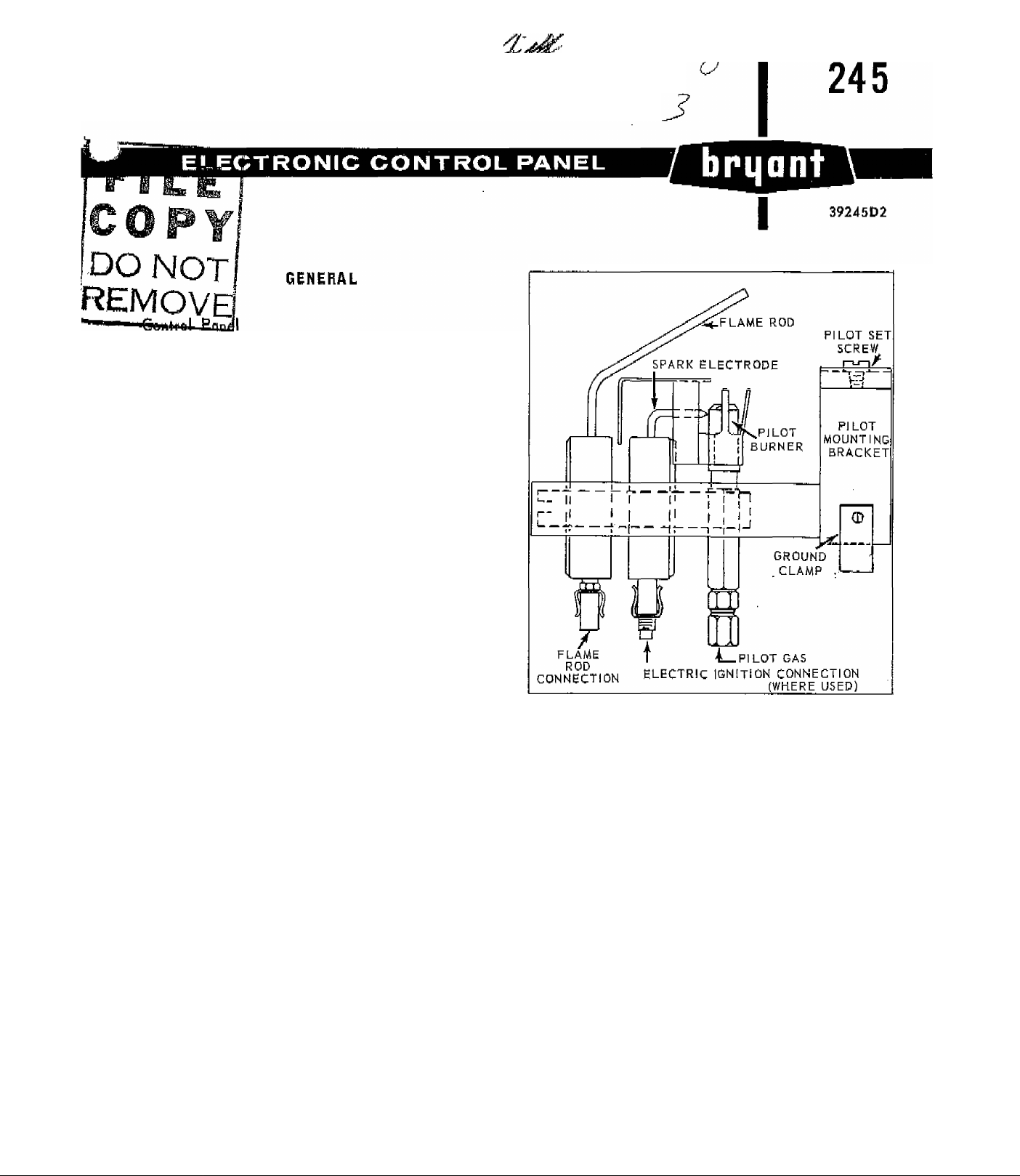
Electronic Pilot
The electronic pilot should be mounted in place of
the automatic pilot nearest the center of the boiler.
There is enough wire furnished for the largest
boiler. What wire is not used should be discarded.
Remove the automatic pilot and install the elec
tronic pilot in its place.
MANUAL IGNITION
For Ndturol Gas-D4 Control Group
This Control Assembly consists of two packages:
1. Package - Electronic Control
a. M-H Control Panel including Protecto-relay.
b. Flame Rod wire (hi-temp) 10 feet.
2. Pilot Package
a. M-H Electronic Pilot
b. Wire nut
c. Ground Clamp
Electronic Control Pilot
Proceed as follows:
1. Mount the Control Panel (see General above).
2. Remove automatic pilot. Install the electronic
pilot in its place.
3. Use the 10 foot length of high temperature flame
rod wire to make electric connection at pilot. Use
14 gauge make up wire to continue the line to the
Control Panel. Make sure a good tight connection
is made. Wire nut is provided. Tape wire to gas
manifold.
4. Ground clamp -Run ¡^14 gauge wire to the Control
Panel ground connection. Tape wire to gas manifold.
EH 245 Kit No, 1
CANCELS; NEW
(SEE OVER)
EFFECTIVE; 2/2a/64
Page 2
S E P / 0 3 .
O B :
ELCS
F A X N o , 3 1 7 2 4 0 B 6 6 6
ELECTRIC
For Natural and Monufncturad Gases - D4 & D5
Control Groups " and LP Gas for D2 Control Groups.
This Control Assembly consists of two packages:
1. Package - Electronic Control
a. M-H Control Panel including Protecto-relay.
b. Flame Rod wire (hi-temp) 10 feet
C- Ignition Transformer
d. High tension wire (Hi-Temp) 10 feet
e. Electric pilot Valve
f. Pilot Tube
2. Pilot Package
a. M-H Electronic Pilot
b. Wire nut
c. Ground clamp
d. 1/8 MP X 1/4 Tube Connection
e. Connections per diagram, Figure 1,
Proceed as follows;
1, Monnt the Control Panel (see General above),
2. Remove automatic pilot.
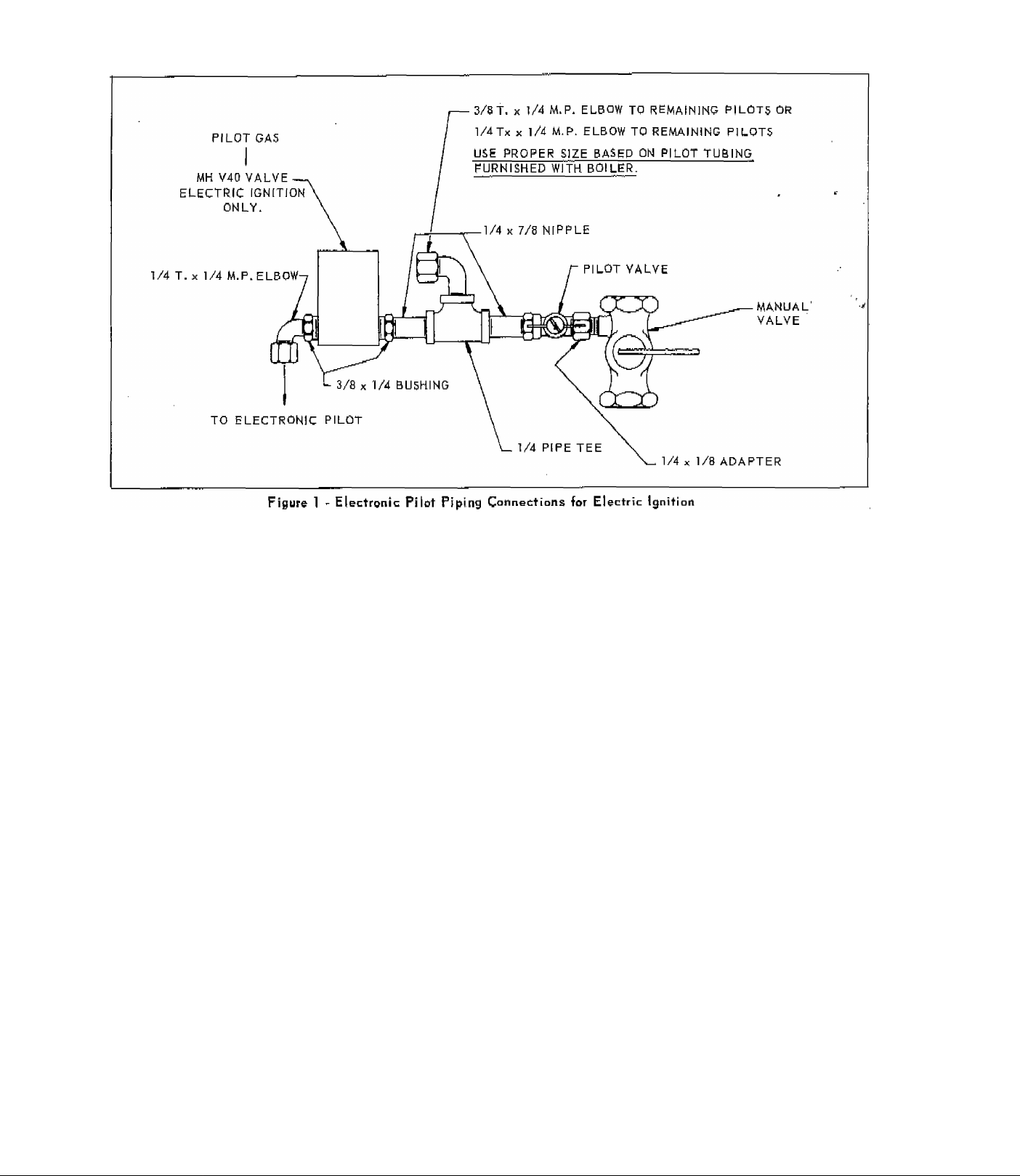
IGNITION
3. Install the Electronic pilot in its place. Make all
connections pet Figure 1. This package contains
fittings for the installation of this pilot on all sizes
of Bryant 245 boilers. This is done for purposes of
standardization. You may have some fittings left
over, depending upon the boiler and type of gas you
are using. Careful inspection of Figure 1 will show
you what fittings to use for your particular boiler.
The excess may be discarded.
4. Install the ignition transformer on the boiler
casing. There are 10 feet of high tension wire used
to connect the pilot lighter with the transformer.
No make up wire is to be used, and therefore the
transformer must be located close enough to the
pilot to be
5. Use the 10 feet of high temperature flame rod
wire to connect to the pilot. Use 14 gauge make
up wire to continue this circuit to the control panel.
A wire nut is provided. (Be sure to make good
tight connections).
6. Run #14 gauge wire from the control panel ground
connection to the ground clamp on the pilot bracket.
Should the transformer not be mounted on the boiler
any approved Hi-Tension wire may be run from the
transformer to the casing.^ The high tension wire
supplied should be used inside the casing only!
able to use this high tension wire.
EH 245 Kit No. 1
-2-
Page 3

CO
•-TZJ
c_o
t-O
HOTI
[GROUKD
THERMOSTAT HEATER
SIZED FOR 0.4 AMR
CURRENT DRAW
m
n
o
3
FORCED WATER CIRCULATION
USING fv1-H RAS32A RELAY
-O
o -,
HOTt
■GROUND
RAB32A
RELAY
GROUND TO
GAS PIPES
GROUNDT THOT
OPERATENG
CONTROL
SAFETY SHUT OFF GAS VALVE (§) £, ©
£4V SECONDARY
GAS VALVE CONTROL
OMIT "W" CONNECTOR
NQN“AUTOMATrC
JNUIN iiiVPIE OTfSl OR PI I GT RELAYS
RECYCLING MANUAL h^lLUHbJOK PILUI RtzLATb
^ 1239 W!RE
)GN, ELEC TRODE
GROUND TO
PILOT
HIGH
LIMET
PILOT GAS VALVE © S. (g)
IGNITION TRANSFORMER
M-H
24V. ROOM THERMOSTAT
SIZED FOR 0.3 AMR DRAW
LOW WATER
CUT OTF
ELECTRONEC PILOT
FLAME ROD
M-H*I29S WIRE
GROUND LUG-H~^
115 V. 60CYCLE I PHASE
0 o
-----
&1 o
Ö
t-O
iLO
CT3
CO
X
m
IO
Cjt
a
THERMOSTAT
HEATER SIZED FOR
0.4 AMP CURRENT
DRAW
M-H L4006B AOUASTAT
FORCED WATER CfRCULATEON
USING RA 132 A RELAY
MOTOR
@ JUMPER TERMINALS - IF NOT USED
(b) LEAVE TERMINAL BLANK -IF NOT USED
(gl PILOT GAS VALVE FOR 100% SHUT OFF AND/OR ELECTRIC IGNITION
M-H V40A OR EQUAL
@ r.LA. OR F. M. SAFETY SHUT-OFF VALVE M-H V4034A OR EQUAL
g) IGNITION TRANSFORMER- M-H 22042
ELECT. PILOT - M-H QI79A - G TIP - 3 INLET FIT. SPARK IGN.
NOTE
FOR CONSTANT PILOT -REMOVE JUMPER SCREW IN RA B^OE
M-H QI79B -G TIP 31NLET FIT. CONSTANT PILOT
c_n
Page 4

m
X
ю
Ul
njO
-TÖ
(_jO
t-o
a
CD
CO
m
n
о
a
TÏ
□
-□cl
>=-
(_jn
cm
cm
cm
 Loading...