

Page 1
S E P / 0 2 / 2 0 0 8 / T U E 0 8 : 1 7 A M
UTC TECH PUB
F A X N o , 3 1 7 2 4 0 5 6 6 2
^ /
MODEL 23^
Inst^llatioiii Instructions
GAS FIRED WATER OR STEAM BOILER
A. G. A. APPROVED
note;: these
[HSTRUCTI ONS
MUSTPE LEFT
ON OR NEAR
THE BOILER.
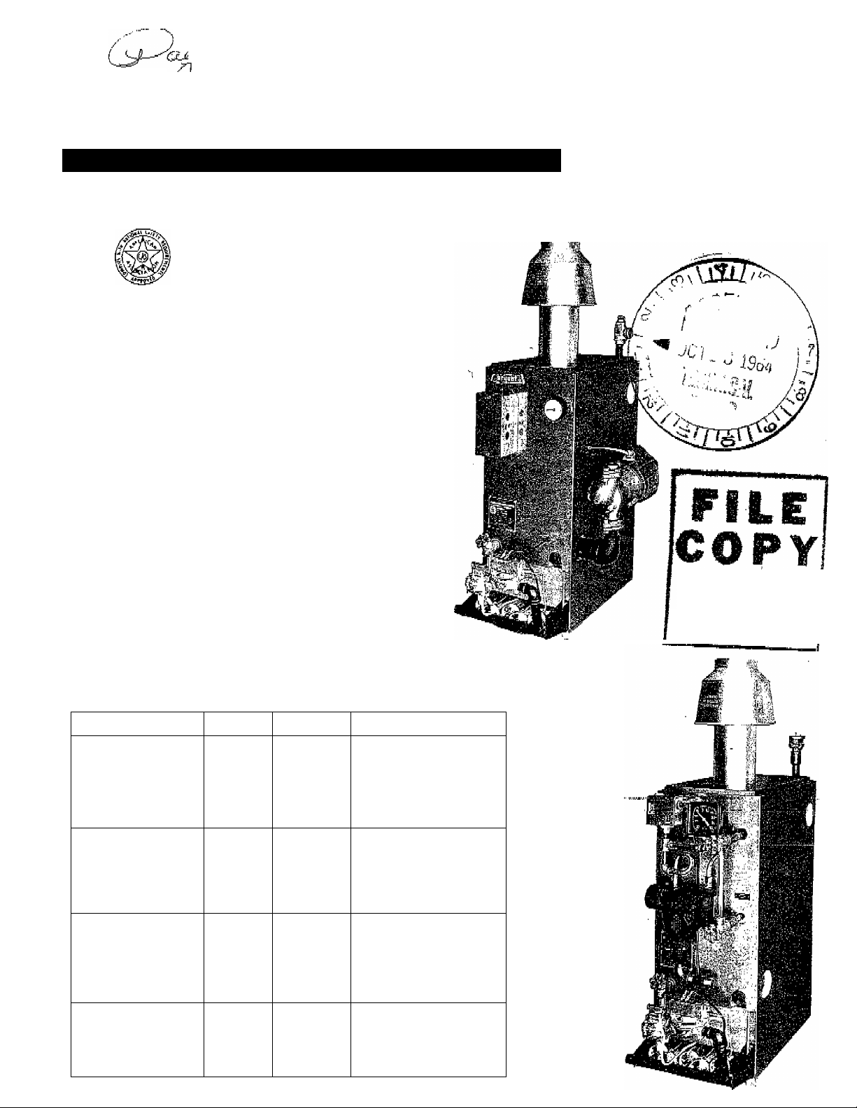
The Model 234 is a low pressure, sectional, cast
iron water and steam boiler, approved by A.G.A. for
use with natural, manufactured and propane gases.
It is tested for a maximum working pressure of 30
psi on water and 15 psi on steam in accordance with
A.3.M.E. standards for cast iron boilers*
The boiler is available as a Type GW - Gravity,
Type PW - Circulation Pump, Type CW - Coil Circu
lation Pump, and Type S - Steam. All boilers are
factory assembled.
SERIES g
I
39234D3
10/5/64
Install in compliance with requirements of local
utility or other agency having jurisdiction.
GAS CONTROL OPTIONS
Control Type
D2
100% shutoff
24 volt
. Thermti'i:oupl'e'"P'ii'o''t
D4
Non 100% shutoff
24 volt
Bryant pilot
D5
100% shutoff
24 volt
Thermocouple pilot
D6
100% shutoff
Millivolt
Thermocouple pilot
Gas Type
Propane PWSiE
Nat&Mfd PW, GW,
Boiler Type
cw&s
NataaMfd PW, GW
CWQlS
Nat&Mfd GW&S Salf-'geh orating
Control Components
100% pilot shutoff valve
Thermocouple pilot
Trans fonner
Biyaiit ■disp'hT'SgÉK ■■■ '
gas valve
Bryant automatic pilot
Bryant diaphragm
gas valve
Gas pressure regulator
Transformer
100% pilot shutoff valve
Thermocouple pilot
Transformer
Bryant diaphragm
gas valve
thermocouple pilot
Diaphragm gas valve
Gas pressure regulator
DO NOT
remove!
Page 2
S E P / 0 2 / 2 0 0 8 / T U E 0 8 : 1 7
UTC TECH PUB
F A X N o , 3 1 7 2 4 0 5 6 6 2
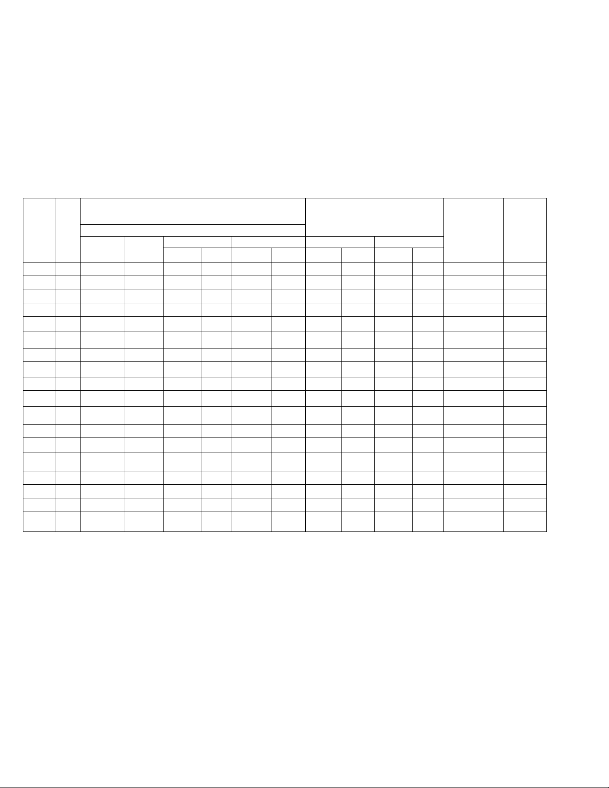
RATINGS AND CAPACITIES
P , 0 0 2
Boiler
Sixie
3
\ 4.
K ■
6
7
l7
5
4
...
5...
6
7
Gross Input BTUH
Type
Nat&MfdpTOpqne
, "i
90,000
PW
PW 125,000
160,000
P,W
;200;Gi3Q.
-EiW <
PW‘ 240,000
•er
It:
w.^ .34b;ow^220,000:
GW‘ iso,oijp:^
..2Oi5;:OQ0'"
■-S
s 105,000
s 175;000 162,500
s 210,000
‘“Ip?!
^60,Mo
¡rSg'ifSSj
‘•'TGjoeb“
.......
............. ’
.440^000 .
85,000 72,000
n0;00:o 100,000’^^67?
ii5o,oao 128,000
I75:00a
220,000 1.92,QQQ:1280;
i ssiOdS-
i^ iTo:oGOi
h.50,Q0p; 128^000' 85:3
^75,000; 16.0,00.0
|!130,0QG; 110,400, 736
N60,000
|200,000 160,000?1067 ,
“ 65,000
97,500 84,000 350
130,000.
195,000 168,000 700
G,r05.5
Nqt^Mfd
BTUHSq.;Ft,
■■■ '#P';
853,
160,000
■1,00,^000^
l92;:O0f
128,0003
112,000 467 .
140,000 583
.;1067^
‘72,ooo;
- .48.0;: 68;ooo 453 54,000
667
1067 140,000' 933 120,000
128:0
853
56,000 234
A,G,A, RATINGS
Output
Propane
BTUH
6s,ooo:■ 453''- 54;00.0
.88,000.
l:20;000 800 96,0:o;o
140/bOO: 933 120,000
N76,000
8S;000 5S7 7'5,000
i;20;ooo, 800
176,000
104,000 695 82,800
128,0.0.0 853 96,000
160,000 1067 120,000
52,000 217 42,000
78,000 325 63,;0.0.0i
104,000..
130,000 543 105,000:
156,000 650 126,000
Sq. Ft/ BTUH Sq. Ft:
75/000'
587
144,000
ii/b
96,000
144,000
1173
..84,G0:O'
.433 .
Net Output
Nat&Mfd
360 ^ 51,000. 340 ’
500 66,000 440
640 90,0Q0
800 TQ5.0.D0700 9.3
960 132,000 880
360 51,000 340
500 66,000
640 90,000 600
800 105,000 700
960 132,000 88.0
552 78,000 520
640 96,000 640
800
175
253 58,500 242
„..350.. ...78,oo:o.325
‘ 4 38 97,000 405
525 117,000
Propane
BTUH Sq. Ft.
120,000 800
39,0.00
600
440
162
487
\
Boiler Water Approx.
Capacit.y in Sh ipping
Galfoas Weight
5.0 277
■ 340
8.0 403
478
IKO
5.0 257
6.5
BX
9.3 448
n.o 500
9.2 415
10.6 ~~4§6
12.2 544
—
-
—
535
318
383
259
318
383
448
500
39234D3
- 2
Page 3
S E P / 0 2 / 2 0 0 8 / T U E 0 8 : 1 7 A M U T C T E C H P U B
OPTIONAL
ENCLOSURE
F A X N o . 3 1 7 2 4 0 5 6 6 2
P . 0 0 3
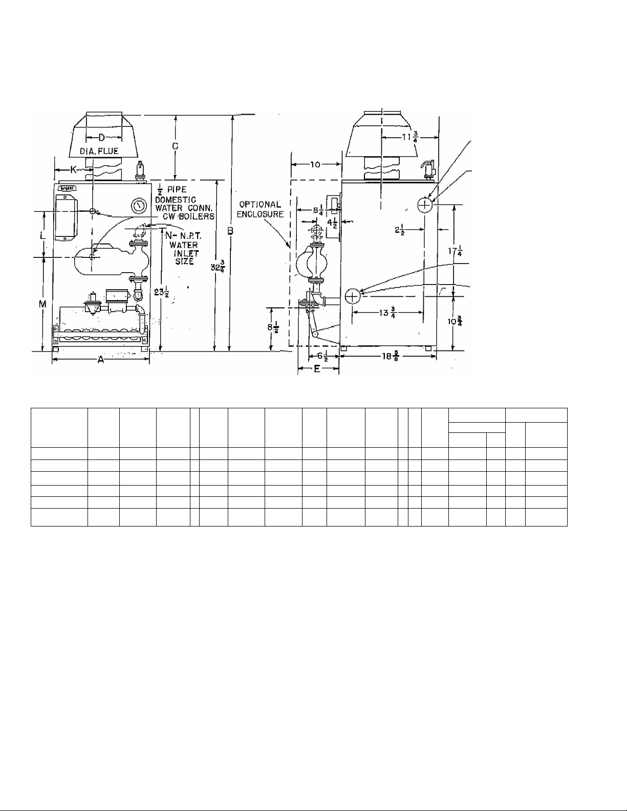
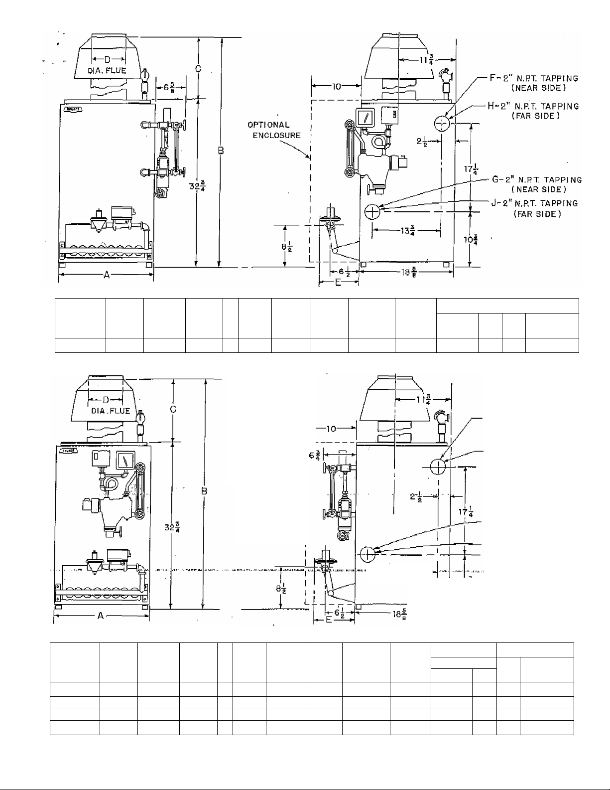
F-‘£“ N,P.T, TAPPING
(NEAR SIDE)
H-a“N.PT TAPPING
(FAR SIDE)
G-£"N.P.T TAPPINQ
'(NEAR SIDE)
J- £"N.RT, TAPPING
( FAR SIDE)
r
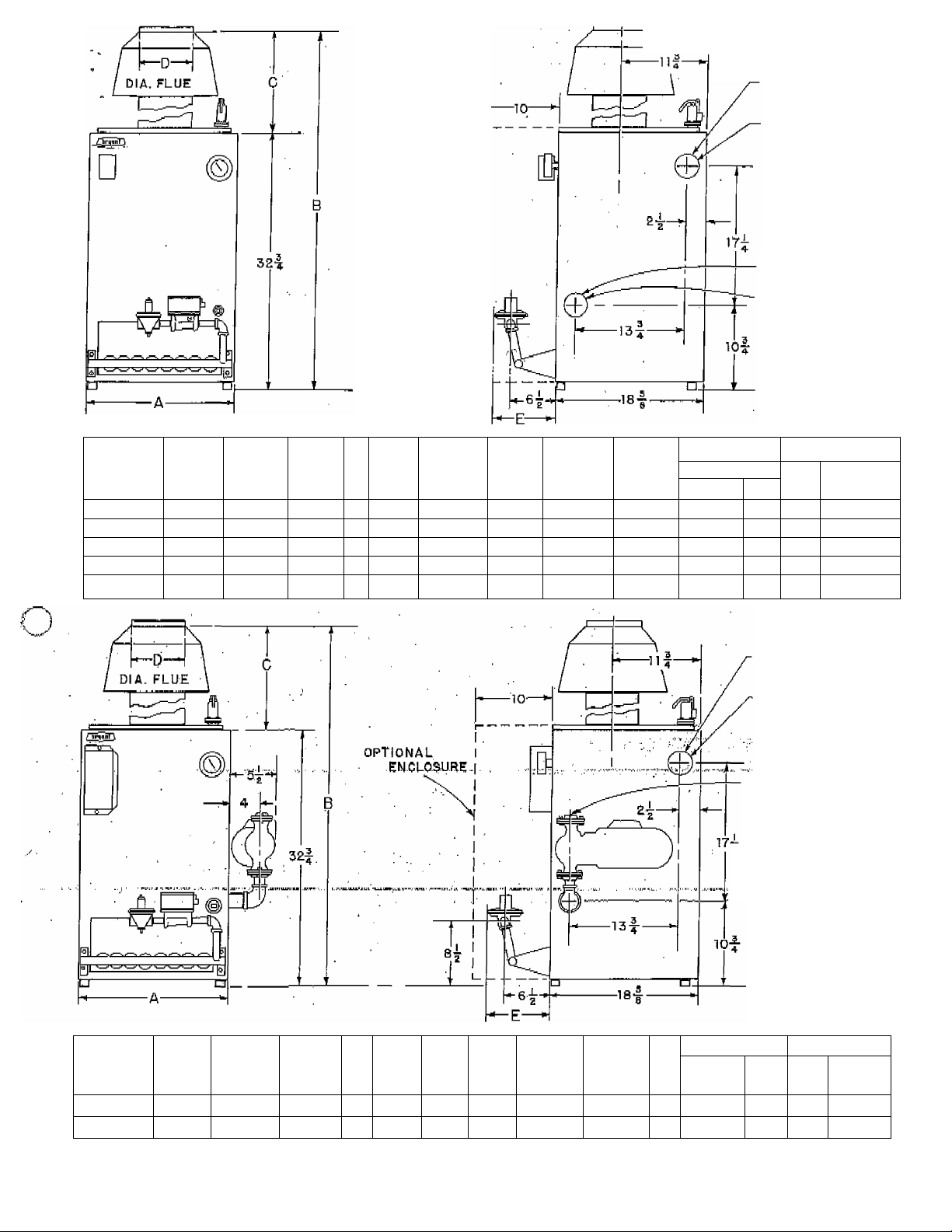
Model
Size A
Type
234-3GW 9-3/4
234-4GW 12-5/8
234-5GW 15-1/2
234-6GW 18.3/8
234-7GW 21-1/4
-
B C
46-9/16 13-3/4 5
46-9/16 13-3/4 5
50-9/16
17-3/4 "6
53-5/16 20-1/2
53-5/16 20-1/2 7
D
E
8-5/8
8-5/8
8-5/8 plugged
7
8-3/S
8-3/S
F G
open open
}*
ft
jjf
tj ft
H
plugged plugged 1/2
M ft
open 1/2
ft y J
J9 J J ft i)
‘
J
Ggs In et Size
Nat Mfd Propane
D4&D5 D6 D5 D2
1/2
ITT™
1/2
1/2 3/4
1/2
3/4
3/4 3/4
3/4 3/4
F- E" N.RT TAPPING
N-N.PT WATER INLET
^ G- £" N.RT. TAPPING
1/2
3/4
-■
—
-
um
-
(NEAR S1D,E)
H-£"N,RT. TAPPING
(FARSi-P^.).
SIZE.
(NEAR SIZE)
tapping'''
(FAR SIDE)
Model
Size&
A
Type
234-3PW
' 9-3/4 46-9/16 13-3/4 5
234-4PW r 12-5/8
B C 0
46-9/16 13-3/4 5
*
E
8-5/8
8-5/8
F G H
open open
li ft
J N Nat
D4&D5
plugged plugged 1 1/2
y y
1 1/2 1/2
Gas In
et Size
Mfd
D6
D5
1/2 1/2 1/2
3/4 1/2
39234D3
Fropgne
D2
Page 4
S E P / 0 2 / 2 0 0 8 / T U E 0 8 : 1 8
UTC TECH PUB
F A X N o , 3 1 7 2 4 0 5 6 6 2
■)
F“e"N,RI TAPPING
(NEAR SIDE )
H“ Z" N,RT TAPPING
(FAR SIDE)
G- 2" N.PT TAPPING
(NEAR SIDE)
J- £" N*RT. TAPPING
(FAR SIDE)
Modd
Size & A
B C D E F G H J
Type
23.4-5PW
15-1/2
50-9/16
234-6PW 18-3/8 53-5/16
17-3/4 6 8-5/8
20-1/2 7 8-3/8
234-7PW 21-1/4 53-5/16 20-1/2 7
234-4CW 15-1/2 50-9/16
..
:234i'5CW.18-3/8,
'234^6CW 2l-i/'4-
53-5/16 20-1/2 7 8-3/8
17-3/4 6 8-5/8
20-1/2, 7 S-.5/8
plugged plugged
8-3/8
plugged —
f7 /7
open
IJ if tt ¡7
J J
J V
tt 97 77 7 7
rr If I f r 1
Gg 9 In et Size
K L M N Nqt MM
D4&D5 D6 DS D2
- -
i-1/4 1/2 1/2 3/4 1/2 .
—
—
-
7-1/2' 9 18 1-1/4
7-1/2. 9 18T-1/4
— 1-1/4
M/2 3/4 3/4:
-
[ li2
1/2
1/2
3/4 3/4 1/2
3/4:
3/4
1/2
1/2
3/4
10-3/8 9 18 1-1/2 1/2 3/4 3/4
Propane
i/2
-
-
muDZ
-4^
Page 5
S E P / 0 2 / 2 0 0 8 / T U E 0 8 : 1 8 A M
UTC TECH PUB
F A X N o , 3 1 7 2 4 0 5 6 6 2
P . 0 0 5
O
Model
SizeSt
Type
234-3S
A
B C
9-3/4 46^9/16
13-3/4
E F
P
5 8-5/8 open
OPTIONAL r
ENCLOSURE
G H
open
plugged
J
plugged
Nat
D4&D5
1/2
Gas Inlet Size
Mfd
Propane
Mfd
D5
D2
1/2 1/2 1/2
F- 2”N.RT. TAPPING
(NEAR SIDE)
N.RT* TAPPING
( FAR SIDE )
G“ 2" N,RT TAPPING
(NEAR SIDE)
J- 2" N. P.T, TAPPING
(FARSiDE)
Model
Size
A
B C
D
E F
G H
J
Type D4&D5
234-4S
234-5S
234-6S
234-7 S
12-S/S
15-1/2
18-3/S
21-1/4
46-9/16 13-3/4
50-9/16
17-3/4
S3-5/16 20-1/2
53-5/16
20-1/2
S-5/S Open
5
6 S-5/3 plugged
,8-3/S
7
7 8-3/8
r r
tt
- 5^
open
plugged
ff
7 7 j i
}t
open
9 J
plugged
i J
1 r
1/2
1/2
1/2
3/4
Gas In
at Size
Nat
Mfd D5 D3
1/2 3/4
"1/2 3/4
3/4 3/4'
3/4 3/4 1/2
Mfd
Propane
1/2
1/2
1/2
39234P3
Page 6

S E P / 0 2 / 2 0 0 8 / T U E 0 8 : 1 8
UTC TECH PUB
ni
N o , 3 1 7 2 4 0 5 6 6 2
P . 0 0 6
LOCATING THE UNIT
Consult local building codes or ordinances that may
apply.
1. The boiler should be installed on a level founda
tion. Metal shims may be used to level if required.
Locate boiler near gas vent or chimney.
2. Combustible Floors - When the boiler is installed
on a combustible floor it is necessary to ¡nsulote
the floor» Bryqnt supplies, as optional equipment, □
combustible floor installation kit. This kit contains
a rectangular plate of galvanized steel with □
matching piece of insulating material. Fasten the
insulation end steel plate to the combustible floor
and place the boiler on fop of the steel plate.
3. Maintain at least 6" from combustible material
on ail sides.
4. Leave enough room for service access. Consult
local approval agency; some require □ minimum of
24" for service access.
5. When unit is installed in a small room, or a build
ing of roiatiyely air-tight'construction, provide air
for combustion and ventilat'iou. This air must be
supplied through two openings of equal area; one
located above the draft diverter relief opening and
the other near the floor. The total free area of each
opening should be equal to 1 square inch for each
1,000 BTU/Hr. of boiler input. There should be a
minimum of 100 square inches for each opening. If
ait openings are directly to outdoors, the minimum
free area should be 1 square .inch per 2,000 BTU per
hour or input rating, or in accordance with Z21.301959 or latest edition of ^'American Standards .for
Inst^Uatiqii of Gas Appliances and Gas Pfpipg/'
2. Flue pipe must slope upward from boiler to chim.- '
ney. Minimum slope is 1/4 inch upward per linear*
foot of flue pipe,
3. Run pipe as directly as possible with a minimum
number of turns.
4. Do not connect into chimney serving an open fire
place,
5. End of flue pipe must be flush with inner face of
chimney liner.
6. Rigidly support pipe with hangers and straps.
7. Chimneys should extend at least two feet above
any object within a radius of 15 feet.
8. All flue pipe extended through the roof should be
equipped with a hood.
9. The boiler may.be installed with either a galvan
ized Type C vent or a listed . Type B yent, at the
option of the installer. Where a Type C flue or vent
connector is used, it shall have a clearance of 6"
between its surface and any combustible material.
If a Type B flue or vent connector is used, clear
ance from its surface to any combustible material
shall be in accordance with its listing. Consult
local codes to insure correctness.
10. Where two or more appliances Vent into a com
mon flue, the area of the common flue should at
least equal the area of the largest flue or yent con
nector plus 50% of the areas of the additional flues
or vent connectors.
GAS SUPPLY LINE
6- Advise owner of necessity for keeping air pas
sages to the boiler area free of obstructions. This
clearance is necessaiy so that combustion air can
enter freely into the combustion chamber. It is also
necessary to provide adequate ventilating air.
FLUE CONNECTIONS
Make sure draft hood furnished with boiler is instal
led without modifications. The following is standard
practice for installing the flue pipe. In addition,
consult local codes and gas company requirements.
1. Flue pipe must be of the same si^re as the outlet
collar on the draft hood.
39234D3
Comply with applicable codes and regulations.
It is good practice to run a separate gas line direct
ly to the gas meter for supplying central heating
boilers. This line should be at least as large as the
-manual "gas shut-off-supplied.. If . the calculated pres^
sure drop exceeds 0.3 inches water, the line should
be run at least one size larger than the usual gas
shut-off. In no case should the drop exceed 0.3
inches water.
The pipe should be. supported with adequate straps
or pipe hangers. Provide a drip leg at the bottom of
the supply riser. Drip leg may extend down to floor
to help support the weight of the gas. supply line.
Install a ground joint union between the riser or
drip leg and the boiler controls. .
Joint compound (pipe dope) which is resistani to the
action of liquefied petroleum gases should be ap-
.6-
Page 7

S E P / 0 2 / 2 0 0 8 / T U E 0 8 : 1 8
UTC TECH PUB
_plied sparingly and only to the male threads of the
Joints. Consult local supplier for type of compound
to he used.
The manual gas shut-off valve should be approxi
mately 5 feet above the floor. Install the valve so
that the 1/8 " tapping used to connect the pilot gas
supply line is located on the inlet (supply) side*
Noter For LP Gas installations the main manual
shut-off valve is an integral part of the 100% shut
off safety control mounted on the manifold with the
electric gas control valve.
Where a pilot gas filter is required by local regula
tions, place filter between manual gas shut-off
valve and pilot valve. See Figure T.
F AX M o . 3 1 7 24 0 5 6 62 P .0 0 7
BOILER WITH REFRIGERATION SYSTEM
VALVES A a В - OPEN FOR HEATING; CLOse FOR COOLING
VALVES C a □ - CLOSE FOR HEATING; OPEN FOR COOLING
When the boiler is used in connection with a refri
geration system it must be installed so that the
chilled medium is piped in parallel with the heating
boiler with appropriate valves to prevent the chilled
medium from entering the heating boiler. An example
of such piping is shown above.
FILTER
PILOT GAS VALVE
Figure 1
ELECTRICAL CONNECTIONS
All electrical connections are to be made in accord
ance with the National Electric Code and local
codes governing such wiring. Field connections are
to be made in accordance with the wiring label
attached to the boiler. These labels are reproduced
in this manual.
When the boiler is connected to heating coils lo
cated in air handling units where they may be ex
posed to refrigerated air circulation, The boiler
piping system must be equipped with flow control
valves or other automatic means to prevent gravity
circulation of the boiler water during^^^^'^^^t^
CAUTIOM, - Note: It is recommended that a relief
valve be installed between valve ,A and the boiler
or valve B and the boiler. This relief valve should
preferobty be on the boiler itself. The relief valve
will protect the boiler from expansion pressures
during the-cooling'seasoni-^ - - ■ -
...
...
- 7 ■
39234D3
Page 8

S E P / 0 2 / 2 0 0 8 / T U E 0 8 : 1 8
STÁRT-.UP AND ADJUSTMENT
Check to be sure that all connections have been
made. Before attempting any operation, fill the
system with water. Never light a burner under an
empty boiler. After filling system with water, bleed
all air from the radiators. Add water and bleed
again. Repeat as necessary until system is free of
air. Open all valves on water supply and- return
lines.
Light the pilot using procedure outlined on the
lighting instruction plate attached to unit However,
when lighting the pilot for the first time, perform the
following additional steps:
1. If the gas supply line, was not purged prior to
connecting the boilet it will be full of air; Since
it would take a long time to.went this ,air thipugh the
small pilot port, it is ,recóMffiended-th^P pilot
supply line be disconnected at the pilot shut-off
valve and the supply line be allowed to purge until
the odoi of gas Is 'dëtected- -;Never:purge ^^Çias- l ines
into the combustion chamber: Itniiiëdiatèly upon
detection of gas odor^ :rëcOnneCt the pilot supply
tube* Allow 5 minutes tO-élápsfe and light the pilot
in accordance with the instructions on the lighting
plate.
2. The pilot Дате should be soft blue' in color.
a. For natural gas controls (D4), this flame should
be of sufficient length to provide good impingment
on the unimetal of the Bryant pilot. Flame should
extend upward between the carry-over ports of the
two adjacent burners. Pilot ñame should not touch
boiler section.
'b.tFof -Dâ and ;D€iUghs'controls, the ñame should
Buïfounid the tip of the thermocouple element of the
piidf and extend downward to include 3/8” to 1/2”
of' the thermocouple. The ñame must never come in
contact with any other part of the thermocouple or
■its lea'd''Wire.“"'The"ña'm6'^li'es'"un'de'r-th'ff“tarr'y-over ^
ports of the burners and merges with the carry-over
flames. Pilot flame should not touch boiler section.
UTC TECH PUB
F A X N o , 3 1 7 2 4 0 5 6 6 2 P . 0 0 8
Light main burners using the procedure outlined on
the metal lighting instruction plate attached, to the
unit.
Adjust gas rate for natural and manufactured gases.
Input should be checked at the meter to make sure
that it corresponds with that shown on the rating
plate attached to the unit.
L Remove 1/8” plug in manifold downstream from
the gas valve and connect manometer to observe
manifold pressure.
2. Set thermostat to call for heat. Be sure that all
other gas using appliances are turned off during
this period of adjustment.
3. Observe manifold pressure. It should be adjusted
to read ,3” w.c. * 0.3" w.q. Adjustment of the pres,sure.^ is accomplished by means of the adjusting
isctew on |he ,gas pressure regulator. (This screw is
concealed under the regulator sealing cap.) Turn
screw clockwise to increase pressure and counter-
blbckwise td decrease pressure.
4. Determine input as follows:
a. Count number of seconds required for one com
plete revolution of dial on the test meter (utility gas
meter).
b. Divide 3,600 by the number of seconds counted
in Item ^a' above.
c. Multiply results of 'b' above by the number of
cubic feet per revolution of the test dial. This gives
cubic feet per hour of gas flow.
d. Multiply results of Item 'c* above by the heat
value of the gas in BTU. (Consult local utility for
this value). This gives the total measured input in
BTU/Hr.
Example:
’"Size of 'test'MeterdiaT-5 icUt'-ft, ■ ■■''■'■ ■ “ ■ .....
Seconds to complete one-revolution -185 seconds
Heating value of gas used-1050 BTU/cu. ft.
.
3. If the pilot flame does not have the appearance
described above, it may be adjusted by means of
the manual pilot shut-off valve (B valve).
a. The valve is equipped with an adjustable screw.
Turn the handle to the full open position and remove
the screw cap to expose the adjustable screw. Turn
adjusting screw until flame has the desired appear
ance.
b- Replace screw cap.
39234D3
Proceed with calculation as follows:
□ . 185 seconds to. complete one revolution
b. 3,600 .divided ’by 185 = 19.5 (approximately)
c. 19.5 X 5 = 97.5 cu. ft./hr. gas flow
d. 97.5 X 1« = 102,375
Small changes in input can be made by changing the
manifold pressure as previously described. However,
the manifold pressure should not vary more than 0.3"
w,c. from the rated pressure of 3” w.c.
Page 9

S E P / 0 2 / 2 0 0 8 / T U E 0 8 : 1 9 A M U T C T E C H P U B
F A X N o . 3 1 7 2 4 0 5 6 6 2
P , 0 0 9
J'urthex change in gas xate can be accomplished if
necessary by changing the fiired orifice to the burners*
Propane Gas: Propane gas units axe not equipped
with gas pressure regulators. Burner orifices are
sized to give the rated input at a manifold pressure
of 11" w.c. The only check for rated input is the
manifold.pressure.
CHECK CONTROLS
Bryant Gas Control Valve: If not already checked
when .iighting the main burner, check" thè proper
opexa'Lon pof This valve. Move the thermòstaf to a
call for diedi position. Observe there-Iwiil^ jAbe an
approxitnetfe 30 'second delay for the vaTye; ip 'ppen.
Move the the mio stai to a satisfied position;, again,
the 30 second -delay before the'.val ve iQlphes,.T' .^^^^
Automatic Pilot'; Check 'the Vìithe
automatic pilot as fòliows;
1. Set the room thermostat bh tail'fpi heaf-
2. After burners have ignited, close the pilot gas
cock.
3. After pilot gas cock is closed, the gas valve will
close in approximately 1 minute. After the pilot gas
is shut off the monometal cools and returns to the
open position. This breaks the circuit to the gas
valve closing the gas valve.
The thermocouple transforms heat energy from the
pilot flame into electrical energy. The current thus
generated is sufficient to operate the 100% shut-off
valve. The Bryant Diaphragm Gas Control Valve is
powered externally from the transformer, and oper
ates independently of the shut-off valve. When there
is a pilot flame, the current generated from the ther
mocouple holds thè 100% shut-off valve in the open
position and the gas control valve controls the flow
of gas. Should the pilot go out, there will be no cur
rent generated fay the thermocouple and the 100%
shut-off valve will close and no gas can flow to the
pilot.
If the pilot should go out, the electrical circuit to
the main gas valve will be broken and gas cannot
flow through the diaphragm valve. '
BRYANT AUTOMATIC PILOT (D4)
The pilot assembly includes a normally open switch
wired in series with the Bryant diaphragm gas con
trol -valve. The switch is at the free end of . the
monometal element assembled so that the fixed end
is positioned at the pilot flame. Heat applied to the
fixed end of the monometal element causes the free
end to move. This closes the switch and completes
the electrical circuit to the control valve. The cir
cuit will close within one minute. It will remain
PILOTS WITH THERMOCOUPLE ELEMENT
The D2 andTÌS gas :x-on|rolV.Mye;p^
with thermocouple elements., , vi
The pilot flame should surround the tip of -the ther
mocouple. It should also extend downward to include
3/8 VTq 1/2." Ql.th§.Th??Lmpcoub^i^^^^ -Th£ flame mu St
not come in contact with any other part of. the ther
mocouple.
- 9 -
^' closed aS long as there is iiori^al pilot flame. .While,
closedTbe ^bbilei tS riiidef tiie difieCf aj^Miiatic con
trol of the ioo^ ojpetating con
trol as long as the ;main gas manual shutpif vATve is
open. If the pilot .ilanie' g^ reason^ the
monometal element will cool and the free end will
move back to its original position. This breaks the
electric circuit and the Bryant diaphragm gas con
trol valve will close. This shuts off the gas supply
to the main burner.
39234D3
Page 10

S E P / 0 2 / 2 0 0 8 / T U E 0 8 : 1 9 A M
GAS PRESSURE REGULATOR
The gas pressure regulator, provided with all units
except those using LP Gas, is of the adjustable
spring loaded type. It functions to give a constant
gas pressure to the burners during all main line gas
pressure fluctuations. This regulator is factory
adjusted to produce 3" manifold pressure.
D6 CONTROLS - SELF-GENERATING
The D6-Control system consists of a powerpile ther
mocouple, a Q314 Pilot Head and a self-generating
thermocouple and a combination valve.
The powerpile thermocouple transforms the heat
energy of the pilot flame into electrical energy
which operates the controls.
Should the pilot flame not be positioned correctly
on the powerpile thermocouple or the pilot flame be
out, there will be no heat energy, hence no electrical
energy-can be generdtedj
UTC TECH PUB
F A X N o , 3 1 7 2 4 0 5 6 6 2
HIGH TEMPERATURE LIMIT
(Wafer Boilers Only)
The high temperature limit switch is a normally
closed switch which opens on temperature rise.
This limit has a cut-out set at 240F and an adjust
able range from 180^ F to 240 ^. F. .When the water
temperature reaches the cut-out setting the circuit
to the gas valve is broken and the gas valve closes.
39234D3
10 -
Page 11

S E P / 0 2 / 2 0 0 8 / T U E 0 8 : 1 9 A M
PRESSURE LIMIT CONTROL
'This control will shnt off the gas supply to the bur
ners in the event that the steam pressure in the
boiler reaches the *'cut-out” setting. It will also
permit gas flow to the burners when the steam pres
sure drops to the “cuHn"* setting. The range be
tween these two settings is called the *'differen
tial”. The cut-out pressure is equal to the cut-in
pressure setting plus the differential.
LOW WATER CUT-OFF
(Steam Boilers Only)
This control operates to shut off the gas supply to
the burner in the event that the water line in the
boiler drops to a low level. It also permits ga^ flow *
to the burners when sufficient water is ^dded to the
boiler, either by opening a water valve manually or
be an electric water feeder.
UTC TECH PUB
(St0am Boilers Only)
^NOT TO BE MADE BEFORE HERE.
F A K N o , 3 1 7 2 4 0 5 6 6 2
ftlbUCTI IN PIPE SIZE
P . 0 1
£" PIPE
' 'Re'coinmefi'dSd''
8t*am heoder
proportions for
175, 210.
Racomm ended
steam Heoder
proportions for
70, 105, 140.
Under no circum-
otoncofi should the
risers he reduced
in six* before the
first horizontal
run.
Under no circtitn-
stances should tl
risers be reducec
in size before th<
first horizontal
run.
- 11 -
39234D3
Page 12

SE P / 02 /2 0 08 / TU E 08 : 20 AM UT C TECH PUB
FAX No, 317 240 5662
P. 012
CLEANING STEAM BOILERS
Caution: The boiler should not be left unattended
during the cleqn-out process.
1, Skimming off Impurities
Some of the impurities in the boiler water will float
on the water .and must be skimmed off. Run a tem
porary connection from the skimmer tee.
With the boiler empty and cool, slowly begin to add
After water has' entered boiler-never beforeturn main gas burners and adjust flame at main
manual shut-off valve so that the water being added
is kept just below boiling point. Avoid boiling and
turbulenceGradually raise hot .Water level to tee being careful
not to raise it above the opening in the tee. Skim
until there is no trace of impurities. Repeat process
if necessary.
Water may be checked to make sure it is free from
oil by drawing off a sample at the skimming tee. If
the sample its reasonably free from oil, it will *not
froth when ^boiled on a stoye. This test does not
indicate the amount'of sedment which may lay in
the bottom of the boiler. It is therefore necessary
that the iboiler ;be further cleaned by 'blowing down'. ,
Sal Soda (washing soda) is sometimes usOd for ex
ceptionally dirty boilers buf its Use requires'e?i-
treme caution. The boiler can be seriously harmed
if the soda is not thoroughly washed out or at least
sufficiently so that the water does riot ekceed the
pH value of 7 to 8. Soda is difficult to ;remo,ve and
requires a lengthy process of repeatedly Hushing
the boiler to assure complete removal. t/
If spjla is insisted ripon it is recommended that a
solution of one pound dissolved in a pail of hot
water, be prepared for each ten gallons of boiler
water. (Check water capacity of boiler). Pour the
solution in any convenient opening at, or above the
flow tapping. Fill boiler to flow tapping and adjust
fire manually to maintain simmering for live or six
hours. Increase fire to build up five pounds pressure
and blow down boiler. '
Blow down boiler again as in Step 2, then flush con
tinuously until it is certain-that boiler is free of the
soda. After the boiler has ‘been thoroughly cleaned,
add fresh, clear water to the proper level in the
heating system. If the degree of acidity or alkalinity
of the water must be adjusted, it is recommended
that the water be mildly alkaline, not exceeding a
pH value of 7 to 8.
).
2. “Blowing Down" Boiler
Before blowing down the boiler, fill if to the water
line. Light burners and allow five pounds of steam
pressure to build up. Run a temporary connection
from one of the drain valyes to a .nearby sewer.
...
Cotih.ect .to a .drain ^v^lve oh ihe oppp the
boiler from the feed water inlet, if possible. Shut
off the gas burners, open drain valve and blow down
entire contents of boiler.
Allow boiler to thoroughly cool and slowly refill to
water line. Repeat Step 2 as many times as required
' until blow'off water is 'clear.
3. Using Cleaning Compound
.................
.
..........
If an exceptional amount of dirt or sludge seems to
be present in the boiler, a boiler cleaning compound
made by a reputable manufacturer may be used ac
cording to the instructions of the manufacturer of
the compound. When any type of cleaning compound
is used, care must be taken to thoroughly flush all
traces of the compound out of the boiler.
..
.
39234D3
12
Page 13

S E P / 0 2 / 2 0 0 8 / T U E 0 8 : 2 0
^Flye Pqssqgei: FJue passages between sections
should be examined yearly and cleaned as required.
Boiler Controls: Check all boiler controls for proper
operation at the start of each heating season. If
boiler is operated year-roundj check controls at
least every six months.
Note: The hand of the TemperaturerAltitude Gauge
should be pre-set by the installer to indicate the
vertical distance between the gauge and the expan
sion tank on open systems. On closed systems, pre-
set the hand to agree with system pressure when
cold. This will normally be about 12 psi. The oper
ating pressure hand should approximately agree
with this setting when the boiler is properly filled.
UTC TECH PUB
CARE AND MAINTENANCE
1 . 8 1 7 2 4 0 5 6 6 2
7 0 1 8
Draining Boiler:
ing seasons. In
Do not drain boiler between heot-
fact, the boiler should never be
drained, flushed, or boiled out unless it is abso
lutely necessary. See special instructions ior blow
ing down steam boilers on start up' when "required.
Leakage; Make certain that there is no leakage in
the system at any time.
Flue Connections; Inspect the flue connection to
the chimney annually to make sure it is in good
condition and has not become obstructed.
CLEANING THE BOILER
1. Remove manifold enclosure and burner access
door.
2. Remove burners and pilot.
3. 'Remove' draft hood" and“Vent“piper' ■ """
4. Loosen top panel and swing aside-
5. Remove flue collector,
6. Use flexible handled wire brush to clean pas
sageways. Remove scrapings from bottom of
boiler.
7. Re-assemble.
Swing Top Panel Aside
- 13 -
Use of Flexible Handled Brush
39234D3
Page 14

S E P / 0 2 / 2 0 0 8 / T U E 0 8 : 2 0
UTC TECH PUB
F A X N o . 8 1 7 2 4 0 5 6 6 2
§
3
E
s 'e
I -
l E
3
ìt о ilk-
o C J
J
^ $ ß
2 2
g (A tn
eoo
о о о
с f“ f“
'Ч- Ю fN
а .û а
^ Ï
“Hi
4}
i
....
)
3
E
№
e
S
m
d
39234D3
U-
Page 15

S E P / 0 2 / 2 0 0 8 / T U E 0 8 : 2 0
U T C T E C H P U B
F A X H o . 3 1 7 2 4 0 5 6 6 2
WATER BOILER WIRING
P . 0 1 5
ROOM THERMOSTAT .55 AMP.
HEAT ANTICIPATOR.
LIMIT
L
|0. ■
SUGGESTED
MANUAL
SWITCH
4___22_^ „
3 : 1
TRANS.
I PR! J
HOrl ;«6R0UND
LOW VOLTAGE
LINE VOLTAGE
RELAY
CIRCULATOR
j' 1
BRYANT
yALVE;,:-
vh, [¡/.'li..
PILOT OR
PILOT RELAY
n
D4 not, mM, non 1005S shutoff
D5 not, mfd, 100% shutoff
Forced circulation with water coil
15-
D2 proparift, jpri% shutoff
D4 not, mfd, no« 100% shutoff
D5 not, mfd; 1Q0% shutoff
Forced circuì dtion
39234D3
Page 16

S E P / 0 2 / 2 0 0 8 / T U E 0 8 : 2 0
UTC TECH PUB
WATER BOILER WIRING
F A X N o , 3 1 7 2 4 0 5 6 6 2
P .
, ^
%
39234D3
- 16
 Loading...