

MODEL 225A
LEGACYt LINE 15 HEAT PUMP
WITH PURONr REFRIGERANT
1--1/2 TO 5 NOMINAL TONS (SIZES 018 TO 060)
Produc t Data
TM
the environmentally sound refrigerant
Bryant’s heat pumps with Puronr refrigerant provide a collection
of features unmatched by any other family of equipment. The
225A has been designed utilizing Bryant’s Puron refrigerant. The
environmentally sound refrigerant allows consumers to make a
responsible decision in the protection of the earth’s ozone layer.
As an Energy Starr Partner, Bryant Heating & Cooling Systems
has determined that this product meets the Energy Star r
guidelines for energy efficiency. Refer to the combination ratings
in the Product Data for system combinations that meet Energy
Starr guidelines.
NOTE: Ratings contained in this document are subject to
change at any time. Always refer to the AHRI directory
(www.ahridirectory.org) for the most up--to--date ratings
information.
INDUSTRY LEADI NG
FEATURES / BENEFITS
Efficiency
15 SEER/ 11.2 -- 13.0 EER/ 7.7 -- 8.8 HSPF (Nominal)
S
S Microtube Technologyt refrigeration system
S Indoor air quality accessories available
Sound
Sound level as low as 70 dBA
S
Comfort
System supports Thermidistatt or standard thermostat
S
controls
Reliability
Puronr refrigerant -- environmentally sound, won’t
S
deplete the ozone layer and low lifetime service cost.
S Front--seating service valves
S Scroll compressor
S Internal pressure relief valve
S Internal thermal overload
S High pressure switch
S Loss of charge switch
S Filter drier
S Balanced refrigeration system for maximum reliability
Durability
DuraGuardt protection package:
S Solid, durable sheet metal construction
S Steel louver coil guard
S Baked--on, complete outer coverage, powder paint
Applications
S
Long--line -- up to 250 feet (76.20 m) total equivalent length,
up to 200 feet (60.96 m) condenser above evaporator, or up to
80 ft. (24.38 m) evaporator above condenser (See Longline
Guide for more information.)
S Low ambient (down to -- 20_F/--28.9_C) with accessory kit
MODEL NUMBER NOMENCLATURE
1234 5 678910111214
N N N A A/N N N N N A/N A/N N A
22 5 A N A 036 0 0 0 A
Product
Famil y
2=HP 2=
the environmentally sound refrigerant
223A
Tier SEER Major
Legacy
Series
5=15 SEER A=Puron N= 208 ---230 ---1
Series
Voltage Variations Cooling Capacity Open Open Open Series
or 208/230 --- 1
A = Standard 0=Not
Defined
ISO 9001:2000
REGISTERED
0=Not
Defined
This product has been designed and
manufactured to meet Energy Star® criteria for
energy efficiency when matched with
appropriate coil components. However, proper
refrigerant charge and proper air flo w are critical
to achieve rated capacity and effi ciency.
Installation of this product should follow all
manufacturing refrigerant charg ing and air flow
instructions. Failur e to confir m proper charge
and air flow may reduce energy efficiency and
shorten equipment life.
0=Not De-
fined
STANDARD FEATURES
Feature 18 24 30 36 42 48 60
Puron Refrigerant X X X X X X X
15 SEER X X X X X X X
Scroll Compressor X X X X X X X
Louvered Coil Guard X X X X X X X
FieldInstalledFilterDrier X X X X X X X
Front Seating Service Valves X X X X X X X
Internal Pressure Relief Valve X X X X X X X
Internal Thermal Overload X X X X X X X
Long Line capability X X X X X X X
Low Ambient capability with Kit X X X X X X X
Suction Line Accumulator X X X X X X X
High Pressure Switch X X X X X X X
Loss of Charge Switch X X X X X X X
A=
Original
Series
X = Standard
2
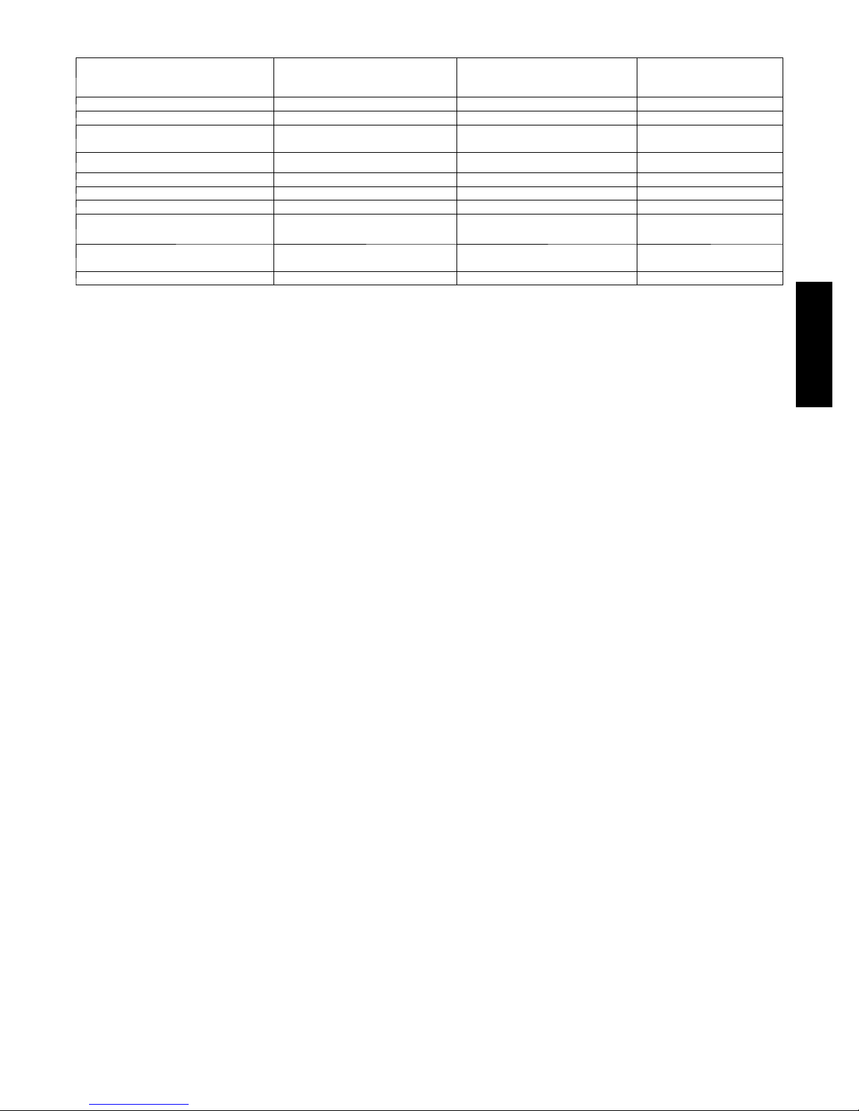
PHYSICAL DATA
UNIT SIZE SERIES 018---B 024 --- B 030 ---B 036--- B 042---B 048---B 060 --- B
Operating Weight lb (kg)
Shipping Weight lb (kg)
Compressor Type Scroll
REFRIGERANT Puron (R---410A)
Control TXV (Puron Hard Shutoff)
Charge lb (kg) 6.4 (2.9) 7.3 (3.3) 11.2 (5.1) 13.2 (6.0) 11.9 (5.4) 13.5 (6.1) 16.2 (7.4)
Outdoor Piston no. 42 46 52 52 59 67 76
COND FAN Propeller Type, Direct Drive
Air Disch arge Vertical
Air Qty (CFM) 2614 3223 3334 3810 3810 4046 4046
Motor HP 1/10 1/12 1/ 8 1/5 1/5 1/4 1/4
Motor RPM 800 800 800 800 800 800 800
COND COIL
Face Are a (S q ft) 15.09 25.15 20.12 22.63 25.15 25.15 30.18
Fins per In. 20 20 20 20 20 20 20
Rows 1 1 2 2 2 2 2
Circuits 5 5 6 6 6 8 10
VALVECONNECT.(In.ID)
Vapor 5/8 5/8 3/4 3/4 7/ 8 7/8 7/8
Liquid 3/8
REFRIGERANT TUBES (In. OD)
Rated Vapor* 5/8 5/8 3/4 3/4 7/8 7/8 1 --- 1 / 8
Liquid 3/8”
*Units are rated with 25 ft (7.6 m) of lineset length. See Vapor Line Sizing and Cooling Capacity Loss table when using other sizes and lengths of lineset.
Note: See unit Installation Instruction for proper installation.
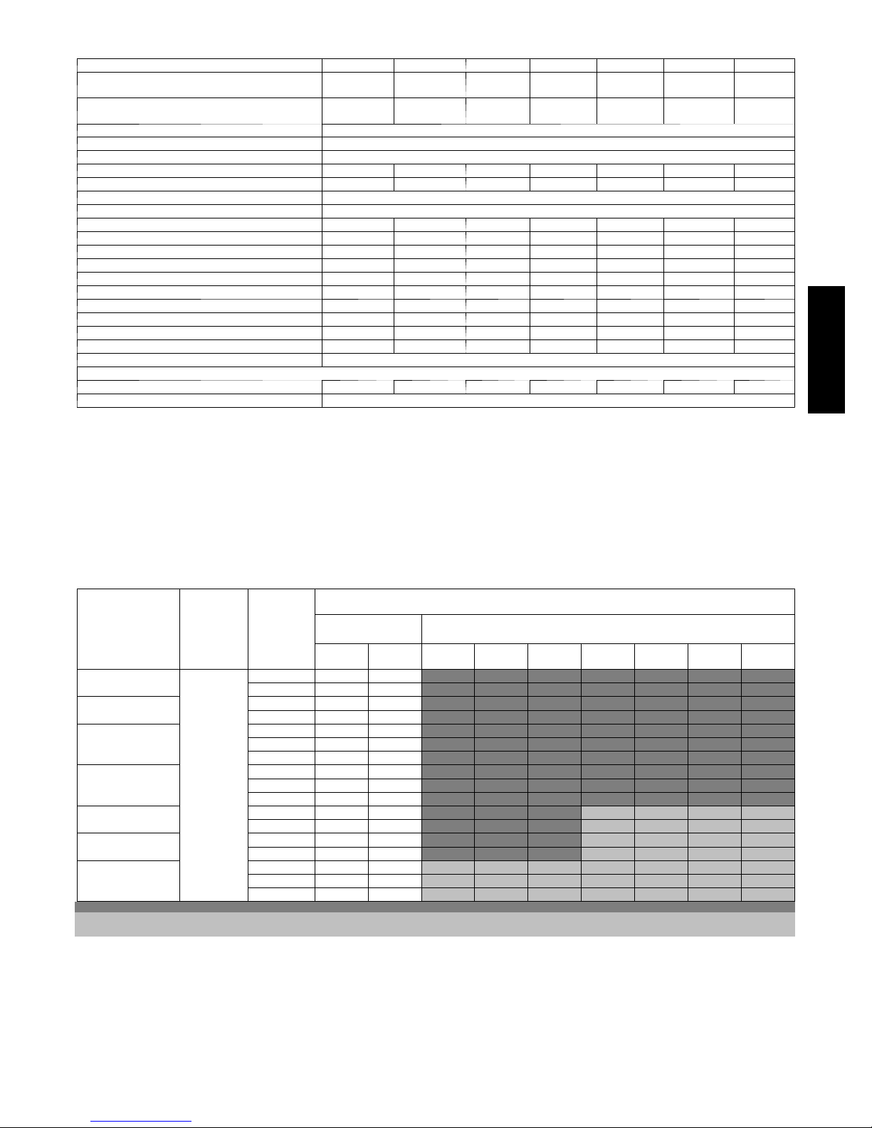
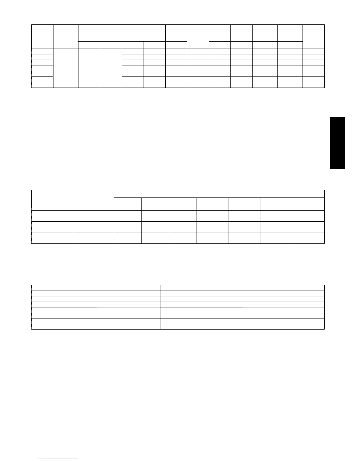
VAPOR LINE SIZING AND COOLING CAPACI TY LOSS
LONG LINE APPLICATION: An application is considered
”Long line” when the total equivalent tubing length exceeds 80
ft. (24.38 m) or when there is more than 20 ft. (6.09 m) vertical
separation between indoor and outdoor units. These applications
require additional accessories and system modifications for
reliable system operation. The maximum allowable total
equivalent length is up to 250 ft. (76.2 m). The maximum
174
(79.0)
201
(91.2)
219
(99.3)
263
(119.3)
247
(112.0)
283
(128.4)
254
(115.2)
291
(132.0)
280
(127.0)
316
(143.3)
302
(134.0)
341
(154.7)
(155.1)
(173.3)
vertical separation is 200 ft. (60.96 m) when outdoor unit is
above indoor unit, and up to 80 ft. (24.38 m) when the outdoor
unit is below the indoor unit. Refer to Accessory Usage Guideline
below for required accessories. See Longline Application
Guideline for required piping and system modifications. Also,
refer to the table below for vapor tube diameters based on the
total length to minimize the cooling capacity loss.
342
382
223A
Cooling Capacity Loss (%)
Unit Nominal Size
(Btuh)
18,000
1 --- S t a g e P u r o n H P
24,000
1 --- S t a g e P u r o n H P
30,000
1 --- S t a g e P u r o n H P
36,000
1 --- S t a g e P u r o n H P
42,000
1 --- S t a g e P u r o n H P
48,000
1 --- S t a g e P u r o n H P
60,000
1 --- S t a g e P u r o n H P
Applications in this area are long line. Accessories are required as shown recommended on Long Line Application Guidelines
Applications in this area may have height restrictions that limit allowable total equivalent length, when outdoor unit is below indoor unit See Long Line Application Guidelines
Maximum
Liquid Line
Diameters
(In.) OD
3/8
Vapo r Li ne
Diameters
(In.) OD
1/2 1 2 3 4 6 7 8 9 10
5/8 0 0 1 1 1 2 2 3 3
5/8 0 1 1 2 3 3 4 4 5
3/4 0 0 0 0 1 1 1 1 1
5/8 1 2 3 3 4 5 6 7 8
3/4 0 0 1 1 1 2 2 2 3
7/8 0 0 0 0 1 1 1 1 1
5/8 1 2 4 5 6 7 9 10 11
3/4 0 0 1 1 2 2 3 3 4
7/8 0 0 0 0 1 1 1 1 2
3/4 0 1 2 2 3 4 4 5 6
7/8 0 0 1 1 1 2 2 2 3
3/4 0 1 2 3 4 5 5 6 7
7/8 0 0 1 1 2 2 2 3 3
3/4 1 2 4 5 6 7 9 10 11
7/8 0 1 2 2 3 4 4 5 5
1 --- 1 / 8 0 0 0 1 1 1 1 1 1
Standard
Application
26---50
(7.9--- 15.2)
51---80
(15.5--- 24.4)
81---100
(24.7--- 30.5)
Total Equivalent Line Length ft. (m)
Long Line Application Requires Accessories
101---125
(30.8--- 38.1)
126---150
(38.4--- 45.7)
151---175
(46.0--- 50.3)
176---200
(53.6--- 60.0)
201---225
(61.3--- 68.6)
226---250
(68.9--- 76.2)
3
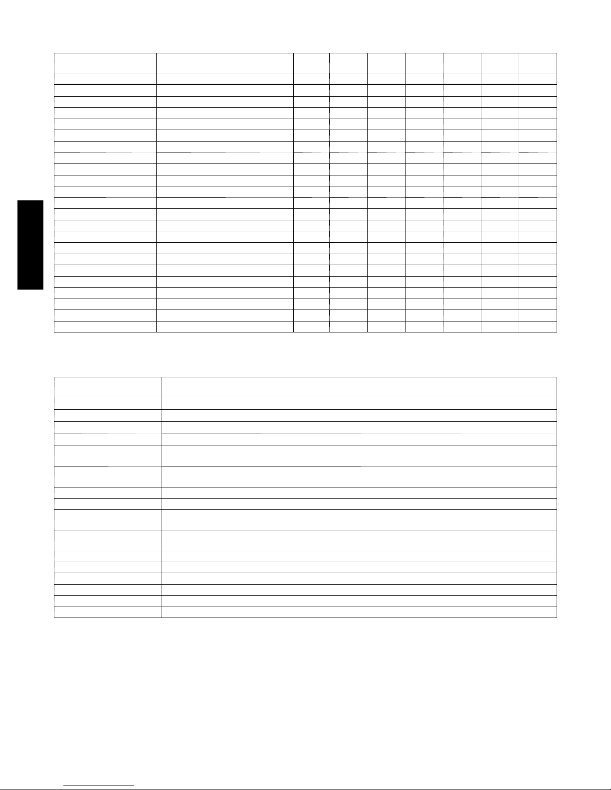
ACCESSORIES
ORDER
NUMBER
KAACH1701AAA CRANKCASE HTR X X
Standard CRANKCASE HTR S S S S S
KAAFT0101AAA FREEZE THERMOSTAT X X X X X X X
KSAHS1701AAA HARD START (CAP/RELAY) X X X X X X X
KHAIR0101AAA ISOLATION RELAY X X X X X X X
KSALA0301410 LOW AMBIENT PSW X X X X X X X
HC34GE242 MOTOR FAN BALL BEARING X
HC32GE229 MOTOR FAN BALL BEARING X
HC36GE232 MOTOR FAN BALL BEARING X
HC38GE228 MOTOR FAN BALL BEARING X X
HC40GE228 MOTOR FAN BALL BEARING X X
KSALA0601AAA MOTORMASTER 230V X X X X X X X
KHAOT0201SEC OUTDOOR THERMOSTAT X X X X X X X
KHAOT0301FST OUTDOOR THERMOSTAT X X X X X X X
KHASS0606MPK* HEAT PUMP SNOW RACK X X X X X X X
KHALS0401LLS SOLENOID VALVE X X X X X X X
223A
KAACS0201PTC STARTASSISTPTC X X X X X X X
KSASF0101AAA SUPPORT FEET X X X X X X X
KAATD0101TDR TIME DELAY X X X X X X X
KSATX0201PUR TXV PURON HSO X X X
KSATX0301PUR TXV PURON HSO X X
KSATX0401PUR TXV PURON HSO X
KSATX0501PUR TXV PURON HSO X
x = Accessory S = Standard
* Order through RCD --- Totaline, par t number KHASS0606MPK (qty 6).
DESCRIPTION 018---B 024-- -B 030 --- B 036---B 042--- B 048 -- -B 060 --- B
ACCESSORY THERMOSTATS
THERMOSTAT / SUBBASE
PKG.
T 6 --- P R H --- 0 1 Programmable Thermidistat
T 6 --- N R H --- 0 1 Non --- programmable Thermidistat
T 2 --- P H P --- 0 1 Legacy Series Programmable HP Stat
T 2 --- N H P --- 0 1 Legacy Series Non ---programmable HP Stat
TSTATBBPRH01--- B*
TSTATBBPHH01--- B*
Thermidistatt Control — Non- -- Programmable/Programmable Thermostat with Humidity Control (For use in
Dual Fuel, AC, HP, and 2S applications. Includes Outdoor Air Temperature Sensor.)
HybridHeatt (Dual Fuel) Thermostat — Auto Changeover, 7 ---Day Programmable, °F/°C, Includes Outdoor
Sensor (TSTATXXSEN01---B)
TSTATBBPHP01---B Thermostat — Auto Changeover, 7 ---Day Programmable, °F/°C , 2 --- S t a g e H e a t , 1 --- S t a g e C o o l
TSTATBBNHP01---C Thermostat — Auto Changeover, Non --- Programmable, °F/°C , 2 --- S t a g e H e a t , 1 --- S t a g e C o o l
TSTATBBSHP01
TSTATBBBHP01* --- B
Standard Programmable Thermostat—Manual Changeover, 5 --- 2 Day Programmable, °F/°C , 1 --- S t a g e H e a t /
1 --- S t a g e C o o l
Builder’s Thermostat — Heat Pump, Non --- Programmable, °F/°C , 2 --- S t a g e H e a t , 1 --- S t a g e C o o l , M a n u a l
Changeover
TSTATXXSEN01 --- B** Outdoor Air Temperature Sensor
TSTATXXNBP01 Backplate for Non --- Programmable Thermostat
TSTATXXPBP01 Backplate for Programmable Thermostat and Thermidistatt Control
TSTATXXSBP01 Backplate for Standard Programmable Thermostat
TSTATXXBBP01 Backplate for Builder’s Thermostat
TSTATXXCNV10{ Thermostat Conversion Kit (4 to 5 Wire) — 10 Pack
* D o not use in zoning heat pump applications.
** Outdoor temperature sensor is an accessory for all Bryant electronic thermostats, except the non --- programmable air conditioner version an d builder;s
thermostats. It allows the temperature at a remote location (outdoors) to be displayed on the thermostat. The outdoor air temperature sensor must be used
with the HybridHeatt (dual fuel) thermostat.
{ Thermostat conversion kit is a 24 ---vac accessory that can turn a 4 --- wire thermostat application into a 5 --- wire application. This kit can also be used to
replace a broken thermostat wire, or add an extra wire when needed.
The outdoor air temperature sensor is included with the Thermidistat Control and HybridHeatt (dual fuel) thermostat.
DESCRIPTION
4
ACCESSORY USAGE GUIDELINE
REQUIRED FOR LOW--- AMBIENT
Accessory
Accumulator Standard Standard Standard
Ball Bearing Fan Motor Ye s{ No No
Compressor Start Assist C apacitor and
Evaporator Freeze Thermostat Ye s No No
Liquid Line Solenoid Valve No
Motor Master® Control or
* For tubing line sets between 80 and 200 ft. (24.38 a nd 60.96 m) and/or 20 ft. (6.09 m) vertical differential, refer to Residential Split --- System Longline
Application Guideline.
{ Additional requirement for Low ---Ambient Controller (full modulation feature) MotorMasterr Control.
Relay
Crankcase Heater Ye s
Hard Shutoff TXV Ye s Ye s Ye s
Isolation Re lay Yes No No
Low Ambient Switch
Support Feet Recommended No Recommended
COOLING APPLICATIONS
(Below 55°F / 12.8°C)
Ye s Ye s No
Ye s No No
REQUIRED FOR
LONG LINE APPLICATIONS*
(Over 80 ft. / 24.38 m)
Ye s
See Long---Line Application
Guideline
REQUIRED FOR
SEA COAST APPLICATIONS
(Within 2 miles / 3.22 km)
No
No
Accessory Description and Usage (Listed Alphabetically)
1. Ball--Bearing Fan Motor
A fan motor with ball bearings which permits speed reduction
while maintaining bearing lubrication.
Usage Guideline:
Required on all units when using MotorMasterr
2. Compressor Start Assist -- Capacitor and Relay
Start capacitor and relay gives a ”hard” boost to compressor
motor at each start up.
Usage Guideline:
Required for reciprocating compressors in the
following applications:
Long line
Low ambient cooling
Hard shut off expansion valve on indoor coil
Liquid line solenoid on indoor coil
Required for single--phase scroll compressors in the
following applications:
Long line
Low ambient cooling
Suggested for all compressors in areas with a history of
low voltage problems.
3. Compressor Start Assist — PTC Type
Solid state electrical device which gives a ”soft” boost to the
compressor at each start--up.
Usage Guideline:
Suggested in installations with marginal power supply.
4. Crankcase Heater
An electric resistance heater which mounts to the base of the
compressor to keep the lubricant warm during off cycles.
Improves compressor lubrication on restart and minimizes the
chance of liquid slugging.
Usage Guideline:
Required in low ambient cooling applications.
Required in long line applications.
Suggested in all commercial applications.
5. Evaporator Freeze Thermostat
An SPST temperature--actuated switch that stops unit operation
when evaporator reaches freeze--up conditions.
Usage Guideline:
Required when low ambient kit has been added.
6. Isolation Relay
An SPDT relay which switches the low--ambient controller out of
the outdoor fan motor circuit when the heat pump switches to
heating mode.
Usage Guideline:
Required in all heat pumps where low ambient kit has
been added.
7. Liquid--Line Solenoid Valve (LLS)
An electrically operated shutoff valve which stops and starts
refrigerant liquid flow in response to compressor operation. It is
to be installed at the outdoor unit to control refrigerant off cycle
migration in the heating mode.
Usage Guideline:
An LLS is required in all long line heat pump
applications to control refrigerant off cycle migration in
the heating mode. See Long Line Guideline.
8. Low --Ambient Pressure Switch Kit
A long life pressure switch which is mounted to outdoor unit
service valve. It is designed to cycle the outdoor fan motor in
order to maintain head pressure within normal operating limits.
The control will maintain working head pressure at low--ambient
temperatures down to 0_F (--17.8_C)when properly installed.
Usage Guideline:
A Low --Ambient Pressure Switch or MotorMasterr
Low--Ambient Controller must be used when cooling
operation is used at outdoor temperatures below 55_F
(12.8_C).
9. MotorMasterr Low--Ambient Controller
A fan--speed control device activated by a temperature sensor,
designed to control condenser fan motor speed in response to the
saturated, condensing temperature during operation in cooling
mode only. For outdoor temperatures down to --20_F (--28.9_C),
it maintains condensing temperature at 100_F ±10_F (37.8_C ±
6.5_C).
Usage Guideline:
A MotorMasterr Low Ambient Controller or
Low
-Ambient Pressure Switch must be used when
-
cooling operation is used at outdoor temperatures
below 55_F (12.8_C).
Suggested for all commercial applications.
223A
5

Accessory Description and Usage (Listed Alphabetically) -- CONTINUED
10. Outdoor Air Temperature Sensor
Designed for use with Bryant Thermostats listed in this
publication. This device enables the thermostat to display the
outdoor temperature. This device also is required to enable
special thermostat features such as auxiliary heat lock out.
Usage Guideline:
Suggested for all Bryant thermostats listed in this
publication.
11. Outdoor Thermostat
An SPDT temperature--actuated switch which turns on
supplemental electric heaters when outdoor air temperature drops
below a user--selected set point.
Usage Guideline:
Electric supplemental heat applications in non --variable
speed indoor units when electric heat staging is desired.
12. Secondary Outdoor Thermostat
An SPDT temperature--actuated switch which turns on
third--stage of supplemental electric heaters when outdoor air
223A
temperature drops below the second-- stage set point.
Usage Guideline:
Outdoor thermostat applications where electric heater is
capable of three--stage operation.
13. Snow Stand
Coated wire rack which supports unit 18 in. (457.2 mm) above
mounting pad to allow for drainage from unit base.
Usage Guideline:
Suggested in the following applications:
Heat pump installations in heavy snowfall areas.
Heat pump installations in snow drift locations.
Heat pump installations in areas of prolonged
subfreezing temperatures.
All commercial installations.
14. Sound Hood
Wraparound sound reducing cover for the compressor. Reduces
the sound level by about 2 dBA.
Usage Guideline:
Suggested when unit is installed closer than 15 ft.
(4.577 m) to quiet areas, bedrooms, etc.
Suggested when unit is installed between two houses
less than 10 ft. (3.05 m) apart.
15. Thermostatic Expansion Valve (TXV) Bi-- Flow
A modulating flow--control valve which meters refrigerant liquid
flow rate into the evaporator in response to the superheat of the
refrigerant gas leaving the evaporator.
Usage Guideline:
Accessory required to meet ARI rating and system
reliability, where indoor not equipped.
Required in all heat pump applications designed with
Puron refrigerant.
16. Time--Delay Relay
An SPST delay relay which briefly continues operation of indoor
blower motor to provide additional cooling after the compressor
cycles off.
Note: Most indoor unit controls include this feature. For those
that do not, use the guideline below.
Usage Guideline:
Accessory required to meet ARI rating, where indoor
not equipped.
6
ELECTRICAL DATA
MIN
UNIT
SIZE
018---B
024---B 58.3 12.8 0.5 16.5 14 14 48 (14.6) 45 (13.7) 25
030---B 73.0 14.4 0.9 18.9 14 14 42 (12.8) 40(12.2) 30
036---B 79.0 16.7 1.2 22.1 12 12 57 (17.4) 54 (16.5) 35
042---B 109.0 22.4 1.2 29.2 10 10 68 (20.7) 65 (19.8) 45
048---B 117.0 22.9 1.2 29.8 10 10 67 (20.4) 64 (19.5) 50
060---B 134.0 26.7 1.2 34.5 8 10 90 (27.4) 55 (16.8) 50
* Permissible limits of the voltage range at which the unit will operate satisfactorily
{ If wire is applied at ambient greater than 30_C, consult table 310 ---16 of the NEC (ANSI/NFPA 70). The ampacity of non --- metallic--- sheathed cable (NM),
trade name ROMEX, shall be that of 60_C conditions, per the NEC (ANSI/NFPA 70) Article 336 --- 26. If other than uncoated (no ---plated), 60 or 75_C
insulation, copper wire (solid wire for 10 AWG or smaller, stranded wire for larger than 10 AWG) is used, consult applicable tables of the NEC (ANSI/NFPA
70).
} Length shown is as measured 1 way along wire path between unit and service panel for voltage drop not to exceed 2%.
* * T i m e --- D e l a y f u s e .
FLA --- F u l l L o a d A m p s
LRA --- L o c k e d R o t o r A m p s
M C A --- Minimu m Circuit Amps
RLA --- RatedLoadAmps
NOTE: Control circuit is 24---V on all units and requires external power source. Copper wire must be used from service disconnect to unit.
All motors/compressors contain internal overload protection.
Complies with 2001 requirements of ASHRAE Standards 90.1
V/PH
208/230/1 253 197
OPER VOLTS* COMPR FAN
MAX MIN LRA RLA FLA 60° C 75° C 60° C 75° C
48.0 9.0 0.7 11.9 14 14 66 (20.1) 62 (18.9) 20
MCA
WIRE
SIZE{
MIN
WIRE
SIZE{
MAX
LENGTH
ft (m)††
MAX
LENGTH
ft (m)††
A--WEIGHTED SOUND POWER
U N I T S I Z E ---
VOLTAGE,
SERIES
018---B 73 58.5 62.5 67.0 67.5 65.5 62.5 53.5
024---B 70 53.0 57.0 63.5 66.0 62.0 60.5 53.5
030---B 71 55.0 62.0 64.5 65.5 63.5 60.5 51.5
036---B 75 59.5 66.5 67.0 70.0 64.5 62.0 54.5
042---B 74 60.0 63.5 65.5 69.0 66.0 62.5 56.5
048---B 72 57.5 63.5 65.0 66.5 64.5 60.0 56.5
060---B 74 60.0 63.5 65.0 67.0 65.0 63.5 56.0
NOTE: Tested in accordance with ARI Standard 270 ---95 (not listed in ARI).
STANDARD
RATING
(dBA)
TYPICAL OCTAVE BAND SPECTRUM (dBA, without tone adjustment)
125 250 500 1000 2000 4000 8000
MAX
FUSE**
or CKT
BRK
AMPS
223A
CHARGING SUBCOOLING (TXV--TYPE EXPANSION DEVICE)
UNIT SIZE --- VOLTAGE, SERIES REQUIRED SUBCOOLING ° F (° C)
018---B 10 (5.6)
024---B 6 (3.3)
030---B 10 (5.6)
036---B 9.5 (5.3)
042---B 9.5 (5.3)
048---B 9.5 (5.3)
060---B 11 (6.1)
7
225A
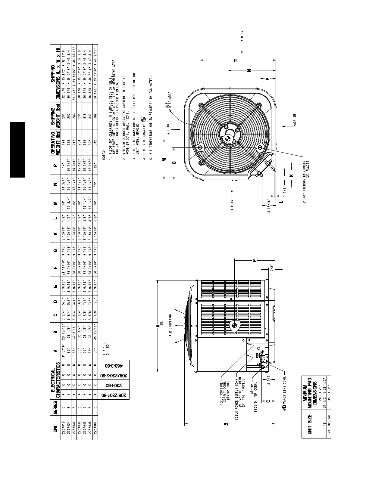
DIMENSIONS -- ENGLISH
8
225A
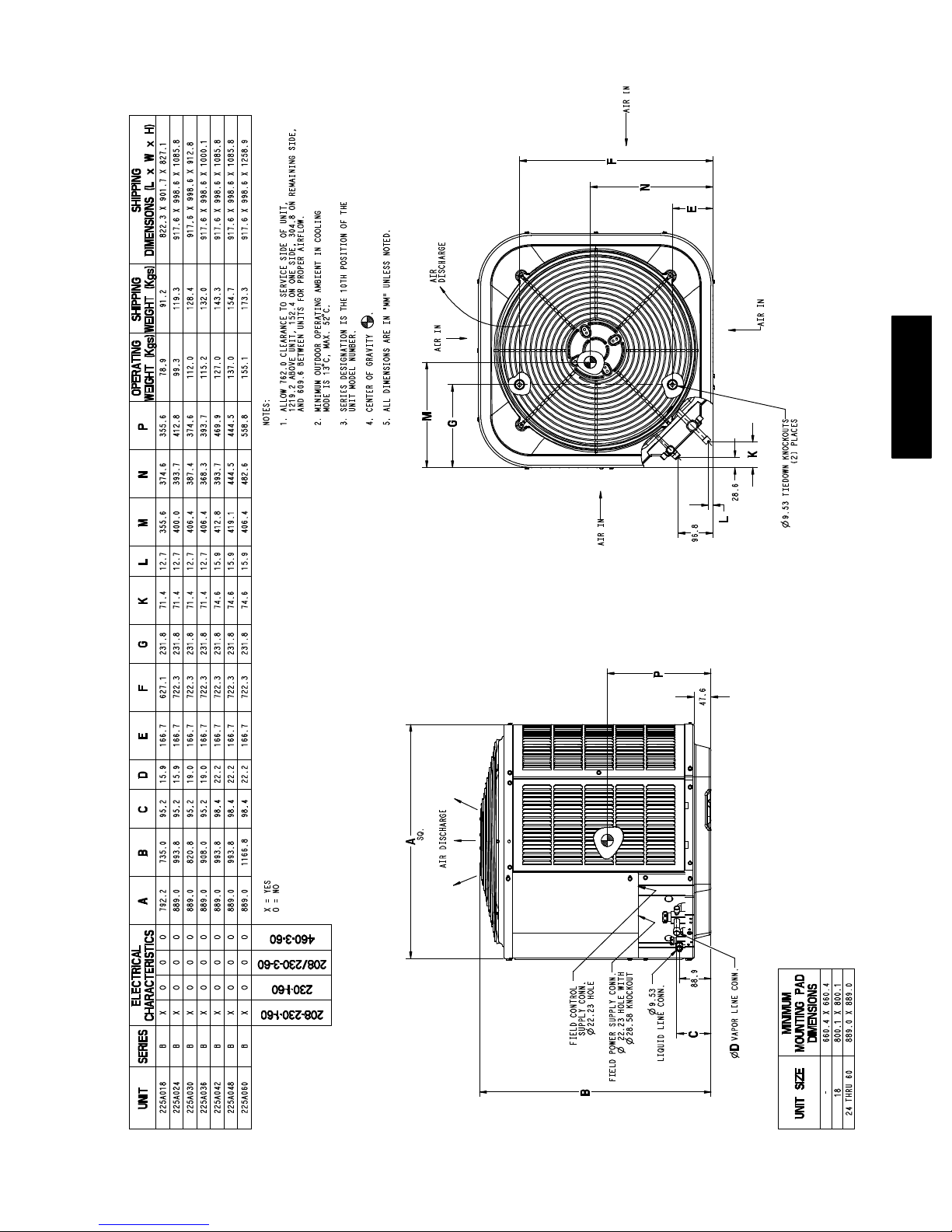
DIMENSIONS -- SI
9
225A
225ANA060
FX4CN(B,F)060
225ANA048
FX4CN(B,F)060
225ANA042
FX4CN(B,F)048
225ANA036
FX4CN(B,F)042
225ANA030
FX4CN(B,F)036
225ANA024
FX4CNF030
225ANA018
FX4CNF018
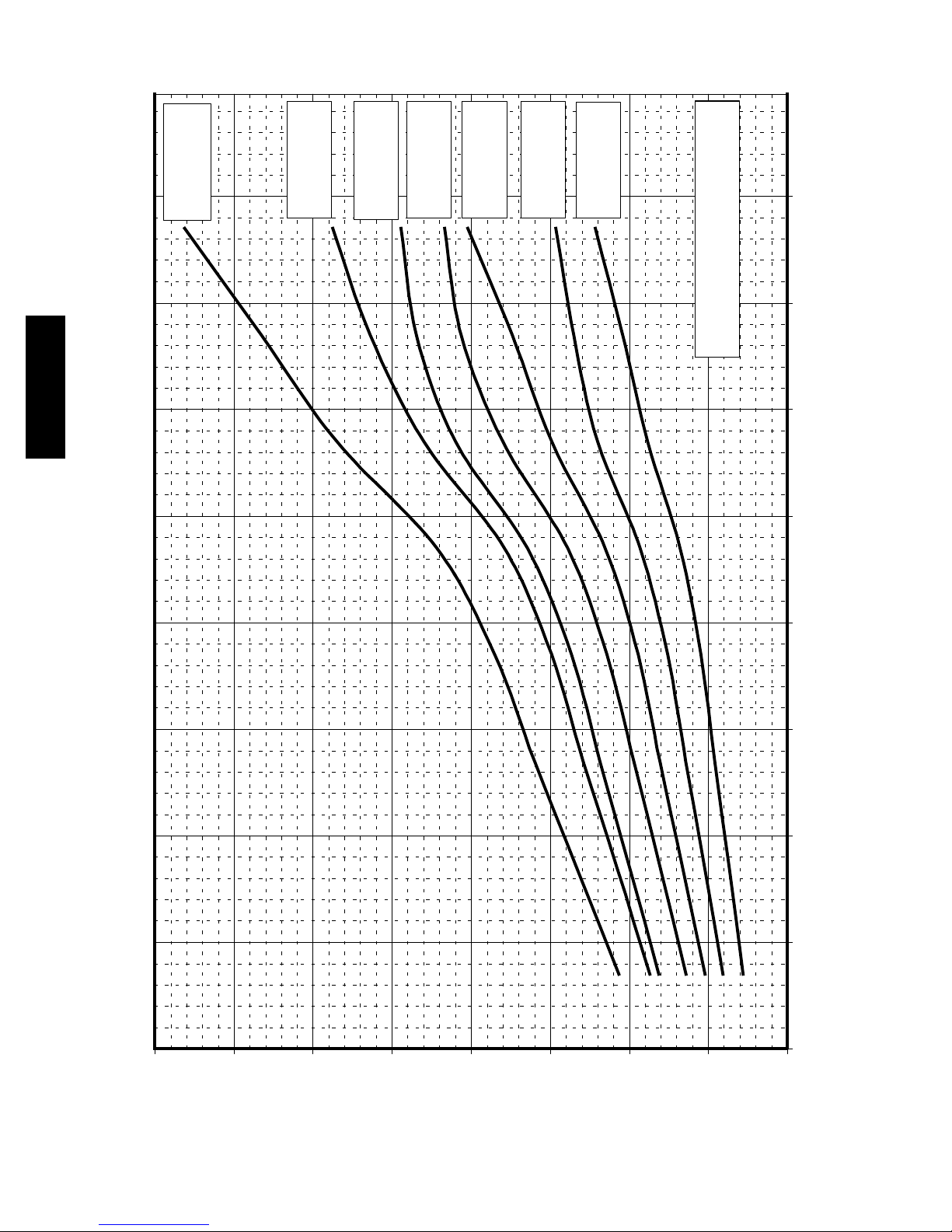
70 (21.11) 80 (26.67)
60 (15.56)
BASED ON INDOOR ENT. AIR
AT 70ºF (21ºC) AND AT RATED CFM
80
70
60
225A BALANCE POINT WORKSHEET
50
40
10
30
OUTDOOR TEMPERATURE, ºF (ºC)
0 (17.78) 10 (-12.22) 20 (-6.67) 30 (-1.11) 40 (4.44) 50 (10)
-10 (-23)
20
10
0
CAPACITY, MBTUH
BUILDING HEAT LOSS, UNIT INTEGRATED HEATING
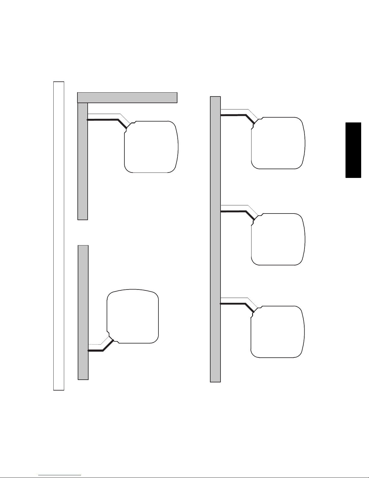
Wall
6”
A07833
(152.4)
24”
Wall
Clearances (various examples)
Service
12”
(304.8)
6”
Wall
(152.4 mm)
12”
(304.8)
12”
(304.8)
12”
(304.8)
Wall
24”
(609.6)
24”
(609.6)
24”
(609.6)
Service
Service
Service
225A
24”
(609.6)
24”
(609.6)
CLEARANCES
24”
(609.6)
Service
11
24”
(609.6)
Note: Numbers in ( ) = mm
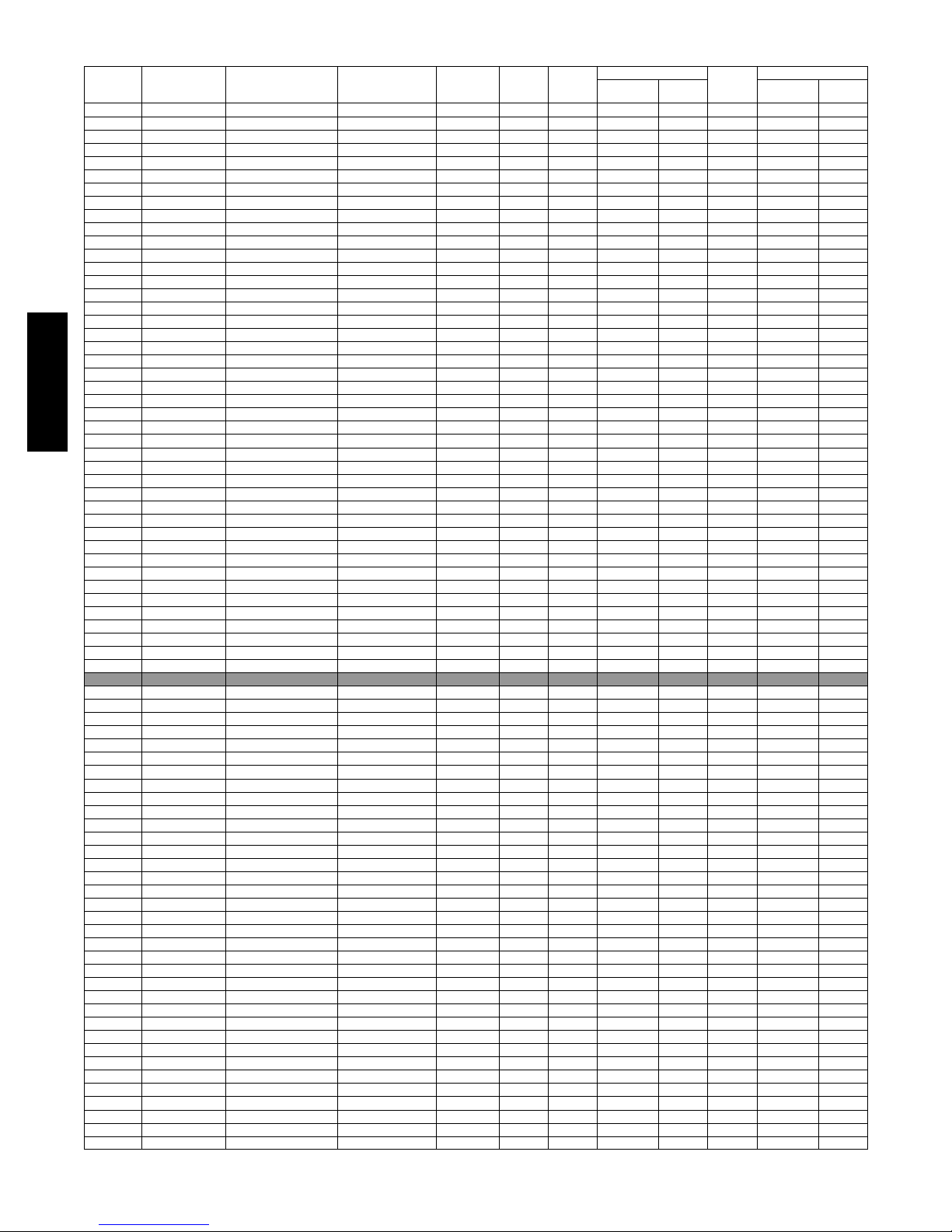
COMBINATION RATINGS
ARI Ref.
No.
3032790 225ANA018 ---B †FX4CNF018 17400 11.7 14.5 17700 3.56 7.7 10300 2.32
3032815 225ANA018 ---B FE4ANF002+UI 17600 12.0 15.0 17500 3.62 8.0 10100 2.36
3032816 225ANA018 ---B FF1ENP018 17000 10.5 13.0 18000 3.36 7.7 10700 2.18
3032817 225ANA018 ---B FF1ENP024 17300 10.7 13.2 18000 3.40 7.7 10700 2.22
3032818 225ANA018 ---B FV4BNF002 17600 12.0 15.0 17500 3.62 8.0 10100 2.36
3032814 225ANA018 ---B FX4CNF024 17600 11.7 14.5 17700 3.60 7.7 10300 2.36
3032812 225ANA018 ---B FY4ANF018 17000 10.5 13.0 18000 3.34 7.7 10700 2.18
3032813 225ANA018 ---B FY4ANF024 17100 10.5 13.0 18000 3.34 7.7 10700 2.18
3032819 225ANA018 ---B CAP**1814A** 313*AV024045 17200 11.5 14.5 17400 3.44 7.7 10100 2.28
3032820 225ANA018 ---B CAP**2414A** 313*AV024045 17600 11.5 14.8 17700 3.62 7.9 10200 2.36
3032791 225ANA018 ---B CAP**2414A** 315(A ,J)AV036070 17200 11.7 14.8 17300 3.46 7.7 10100 2.30
3032793 225ANA018 ---B CAP**2417A** 315(A ,J)AV048090 17300 11.7 14.8 17400 3.50 7.7 10100 2.30
3106434 225ANA018 ---B CAP**2417A** 353AAV036040 17900 12.0 15.0 17800 3.78 8.2 10300 2.42
3106435 225ANA018 ---B CAP**2417A** 353AAV036060 17700 12.0 15.0 17700 3.68 8.2 10200 2.38
3032792 225ANA018 ---B CAP**2417A** 355(A,C)AV042060 17200 11.7 14.8 17400 3.48 7.7 10100 2.30
3032805 225ANA018 ---B CNPF*2418A**+TDR 17300 10.7 13.2 18000 3.50 7.7 10800 2.24
3032823 225ANA018 ---B CNPH*2417A** 313*AV024045 17500 11.5 14.8 17700 3.64 8.0 10200 2.34
3032803 225ANA018 ---B CNPH*2417A** 315(A,J)AV036070 17200 11.7 14.8 17400 3.52 7.7 10100 2.30
3032804 225ANA018 ---B CNPH*2417A** 315(A,J)AV048090 17300 11.7 14.8 17500 3.54 7.7 10100 2.32
3106438 225ANA018 ---B CNPH*2417A** 353AAV036040 17700 12.0 15.0 17800 3.76 8.2 10300 2.40
3106439 225ANA018 ---B CNPH*2417A** 353AAV036060 17500 12.0 15.0 17600 3.64 7.9 10100 2.36
3032800 225ANA018 ---B CNPH*2417A** 355(A,C)AV042040 17200 11.7 14.8 17500 3.52 7.7 10100 2.32
3032801 225ANA018 ---B CNPH*2417A** 355(A,C)AV042060 17200 11.7 14.8 17400 3.52 7.7 10100 2.32
223A
3032802 225ANA018 ---B CNPH*2417A** 355(A,C)AV042080 17300 11.7 14.8 17500 3.54 7.7 10100 2.32
3032799 225ANA018 ---B CNPH*2417A**+TDR 17300 10.7 13.2 18000 3.50 7.7 10800 2.24
3032821 225ANA018 ---B CNPV*1814A** 313*AV024045 17300 11.5 14.5 17600 3.52 7.7 10200 2.30
3032822 225ANA018 ---B CNPV*2414A** 313*AV024045 17500 11.5 14.8 17700 3.64 8.0 10200 2.34
3032795 225ANA018 ---B CNPV*2414A** 315(A,J)AV036070 17200 11.7 14.8 17400 3.52 7.7 10100 2.30
3032794 225ANA018 ---B CNPV*2414A**+TDR 17300 10.7 13.2 18000 3.50 7.7 10800 2.24
3032798 225ANA018 ---B CNPV*2417A** 315(A,J)AV048090 17300 11.7 14.8 17500 3.54 7.7 10100 2.32
3106436 225ANA018 ---B CNPV*2417A** 353AAV036040 17700 12.0 15.0 17800 3.76 8.2 10300 2.40
3106437 225ANA018 ---B CNPV*2417A** 353AAV036060 17500 12.0 15.0 17600 3.64 7.9 10100 2.36
3032797 225ANA018 ---B CNPV*2417A** 355(A,C)AV042060 17200 11.7 14.8 17500 3.52 7.7 10100 2.32
3032796 225ANA018 ---B CNPV*2417A**+TDR 17300 10.7 13.2 18000 3.50 7.7 10800 2.24
3032824 225ANA018 ---B CSPH*2412A** 313*AV024045 17600 11.5 14.8 17700 3.60 7.9 10200 2.34
3032810 225ANA018 ---B CSPH*2412A** 315(A,J)AV036070 17300 11.7 14.8 17400 3.50 7.7 10100 2.30
3032811 225ANA018 ---B CSPH*2412A** 315(A,J)AV048090 17400 11.7 14.8 17500 3.52 7.7 10100 2.32
3106440 225ANA018 ---B CSPH*2412A** 353AAV036040 17700 12.0 15.0 17700 3.68 8.2 10200 2.38
3106441 225ANA018 ---B CSPH*2412A** 353AAV036060 17500 12.0 15.0 17400 3.56 7.8 10100 2.32
3032807 225ANA018 ---B CSPH*2412A** 355(A,C)AV042040 17400 11.7 14.8 17400 3.50 7.7 10100 2.30
3032808 225ANA018 ---B CSPH*2412A** 355(A,C)AV042060 17400 11.7 14.8 17500 3.52 7.7 10100 2.30
3032809 225ANA018 ---B CSPH*2412A** 355(A,C)AV042080 17400 11.7 14.8 17500 3.52 7.7 10100 2.32
3032806 225ANA018 ---B CSPH*2412A**+TDR 17500 10.7 13.2 18000 3.50 7.7 10800 2.24
Model
Number
Coil Model Number
Furnace
Model Number
Cooling
Capacity
EER SEER
High Temp
E
Capacity
ECOP
HSPF
Low Temp
H
CapacityHCOP
3032825 225ANA024 ---B †FX4CNF030 23600 12.5 15.3 24000 3.86 8.8 14700 2.66
3032897 225ANA024 ---B FE4AN(B,F)003+UI 23600 13.0 15.5 23600 3.80 8.8 14400 2.68
3032896 225ANA024 ---B FE4ANF002+UI 23400 12.5 15.5 24000 3.82 8.8 14500 2.66
3032898 225ANA024 ---B FF1ENP024 23000 11.0 13.5 24000 3.56 8.2 15200 2.46
3032899 225ANA024 ---B FF1ENP030 23000 11.2 13.5 24000 3.58 8.3 15200 2.48
3032901 225ANA024 ---B FV4BN(B,F)003 23600 13.0 15.5 23600 3.80 8.8 14400 2.68
3032900 225ANA024 ---B FV4BNF002 23400 12.8 15.5 24000 3.82 8.8 14500 2.66
3032895 225ANA024 ---B FX4CNF024 23200 12.0 15.0 24000 3.74 8.6 14700 2.60
3032893 225ANA024 ---B FY4ANF024 22800 11.2 13.5 24000 3.56 8.2 15100 2.48
3032894 225ANA024 ---B FY4ANF030 23200 11.5 14.0 24000 3.66 8.5 15200 2.52
3032904 225ANA024 ---B CAP**2414A** 313*AV024045 23200 12.0 15.0 24000 3.70 8.5 14600 2.60
3032827 225ANA024 ---B CAP**2414A** 315(A ,J)AV036070 23000 12.5 15.0 23800 3.62 8.4 14400 2.58
3032826 225ANA024 ---B CAP**2414A**+TDR 23000 11.2 13.5 24000 3.62 8.4 15200 2.50
3032830 225ANA024 ---B CAP**2417A** 315(A ,J)AV048090 23000 12.5 15.0 23800 3.66 8.5 14400 2.60
3106442 225ANA024 ---B CAP**2417A** 353AAV036040 23400 12.5 15.5 24000 3.84 8.7 14600 2.68
3106443 225ANA024 ---B CAP**2417A** 353AAV036060 23600 12.5 15.5 24000 3.86 8.8 14600 2.68
3106444 225ANA024 ---B CAP**2417A** 353AAV036080 23400 12.5 15.5 24000 3.82 8.7 14500 2.66
3032829 225ANA024 ---B CAP**2417A** 355(A,C)AV042060 23000 12.5 15.0 23800 3.64 8.4 14400 2.60
3032828 225ANA024 ---B CAP**2417A**+TDR 23000 11.2 13.5 24000 3.62 8.4 15200 2.50
3032905 225ANA024 ---B CAP**3014A** 313*AV024045 23400 12.5 15.3 23800 3.72 8.6 14600 2.62
3032832 225ANA024 ---B CAP**3014A** 315(A ,J)AV036070 23200 12.5 15.0 23600 3.66 8.5 14400 2.60
3032831 225ANA024 ---B CAP**3014A**+TDR 23400 11.2 13.5 24000 3.58 8.4 15300 2.52
3032835 225ANA024 ---B CAP**3017A** 315(A ,J)AV048090 23400 12.8 15.5 23600 3.72 8.6 14400 2.62
3106445 225ANA024 ---B CAP**3017A** 353AAV036040 23800 12.5 15.5 23800 3.86 8.8 14600 2.70
3106446 225ANA024 ---B CAP**3017A** 353AAV036060 24000 12.5 15.5 23800 3.86 8.8 14600 2.72
3106447 225ANA024 ---B CAP**3017A** 353AAV036080 23800 12.5 15.5 23800 3.82 8.8 14600 2.70
3032834 225ANA024 ---B CAP**3017A** 355(A,C)AV042060 23200 12.5 15.5 23600 3.70 8.5 14400 2.62
3032833 225ANA024 ---B CAP**3017A**+TDR 23400 11.2 13.5 24000 3.58 8.4 15300 2.52
3032870 225ANA024 ---B CNPF*2418A**+TDR 23000 11.2 13.5 24000 3.70 8.5 15300 2.52
3032908 225ANA024 ---B CNPH*2417A** 313*AV024045 23000 12.0 15.0 24000 3.74 8.5 14600 2.60
3032853 225ANA024 ---B CNPH*2417A** 315(A,J)AV036070 22800 12.0 15.0 24000 3.68 8.5 14500 2.60
3032854 225ANA024 ---B CNPH*2417A** 315(A,J)AV048090 23000 12.5 15.3 24000 3.72 8.6 14400 2.62
3032855 225ANA024 ---B CNPH*2417A** 315(A,J)AV060110 23000 12.0 15.0 24000 3.72 8.5 14500 2.60
3032856 225ANA024 ---B CNPH*2417A** 315(A,J)AV066135 23000 12.5 15.3 24000 3.72 8.6 14500 2.60
3032857 225ANA024 ---B CNPH*2417A** 315(A,J)AV066155 23000 12.5 15.3 24000 3.72 8.6 14500 2.62
See notes on pg. 21
12
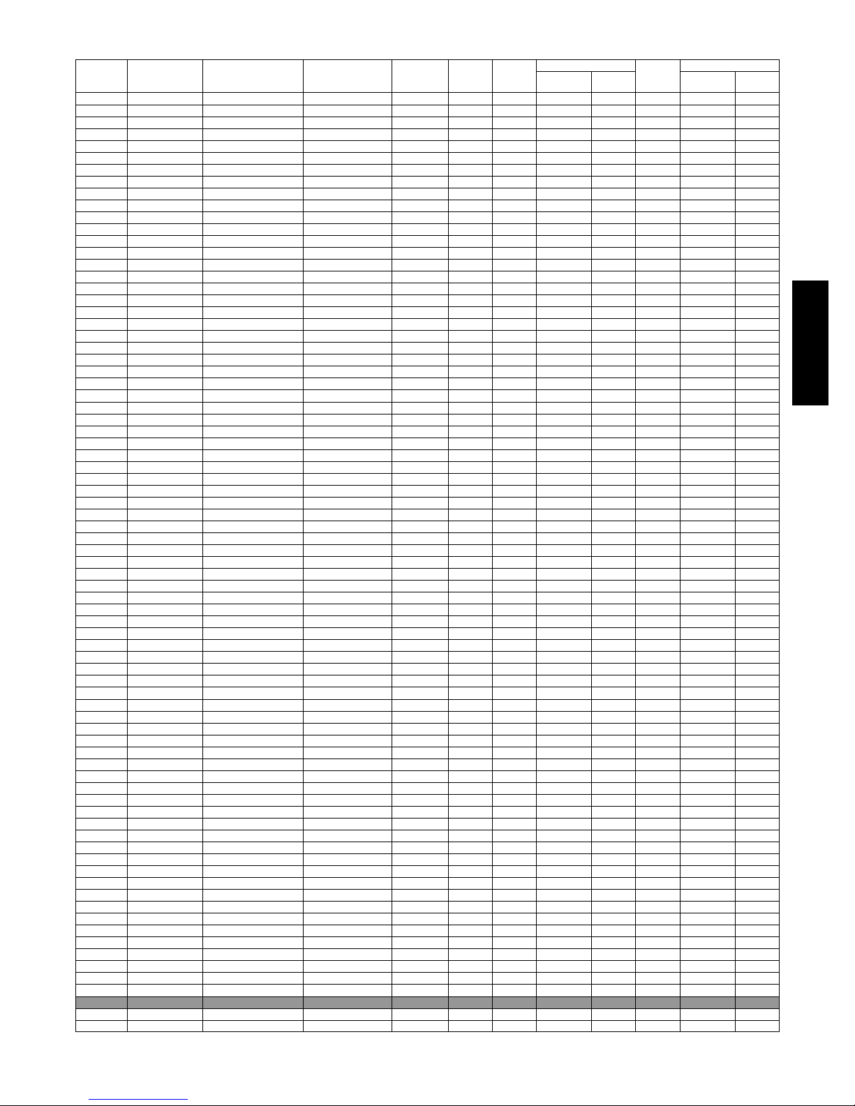
COMBINATION RATINGS CONTINUED
ARI Ref.
No.
3106454 225ANA024 ---B CNPH*2417A** 353AAV036040 23200 12.5 15.0 24000 3.84 8.7 14600 2.66
3106455 225ANA024 ---B CNPH*2417A** 353AAV036060 23200 12.5 15.0 24000 3.86 8.7 14600 2.66
3106456 225ANA024 ---B CNPH*2417A** 353AAV036080 23200 12.5 15.0 24000 3.82 8.7 14600 2.64
3032847 225ANA024 ---B CNPH*2417A** 355(A,C)AV042040 23000 12.0 15.0 24000 3.72 8.5 14500 2.60
3032848 225ANA024 ---B CNPH*2417A** 355(A,C)AV042060 23000 12.5 15.3 24000 3.70 8.5 14500 2.60
3032849 225ANA024 ---B CNPH*2417A** 355(A,C)AV042080 23000 12.0 15.0 24000 3.72 8.5 14500 2.60
3032850 225ANA024 ---B CNPH*2417A** 355(A,C)AV060080 23000 12.0 15.0 24000 3.70 8.5 14500 2.60
3032851 225ANA024 ---B CNPH*2417A** 355(A,C)AV060100 23000 12.5 15.3 24000 3.72 8.6 14500 2.62
3032852 225ANA024 ---B CNPH*2417A** 355(A,C)AV060120 22800 12.0 15.0 24000 3.68 8.5 14500 2.58
3032846 225ANA024 ---B CNPH*2417A**+TDR 23000 11.2 13.5 24000 3.70 8.3 15300 2.52
3032909 225ANA024 ---B CNPH*3017A** 313*AV024045 23600 12.5 15.3 23800 3.76 8.7 14600 2.64
3032865 225ANA024 ---B CNPH*3017A** 315(A,J)AV036070 23200 12.5 15.5 23600 3.68 8.5 14400 2.60
3032866 225ANA024 ---B CNPH*3017A** 315(A,J)AV048090 23400 12.8 15.5 23600 3.72 8.6 14400 2.64
3032867 225ANA024 ---B CNPH*3017A** 315(A,J)AV060110 23400 12.5 15.5 23600 3.72 8.6 14400 2.62
3032868 225ANA024 ---B CNPH*3017A** 315(A,J)AV066135 23400 12.5 15.5 23600 3.72 8.6 14400 2.64
3032869 225ANA024 ---B CNPH*3017A** 315(A,J)AV066155 23400 12.5 15.5 23600 3.72 8.6 14400 2.64
3106457 225ANA024 ---B CNPH*3017A** 353AAV036040 23800 12.5 15.5 23600 3.86 8.8 14600 2.70
3106458 225ANA024 ---B CNPH*3017A** 353AAV036060 24000 12.5 15.5 23600 3.86 8.8 14700 2.72
3106459 225ANA024 ---B CNPH*3017A** 353AAV036080 23800 12.5 15.5 23600 3.82 8.8 14600 2.68
3032859 225ANA024 ---B CNPH*3017A** 355(A,C)AV042040 23400 12.5 15.5 23600 3.70 8.6 14500 2.62
3032860 225ANA024 ---B CNPH*3017A** 355(A,C)AV042060 23200 12.5 15.5 23600 3.70 8.5 14400 2.62
3032861 225ANA024 ---B CNPH*3017A** 355(A,C)AV042080 23400 12.5 15.5 23600 3.70 8.6 14500 2.62
3032862 225ANA024 ---B CNPH*3017A** 355(A,C)AV060080 23400 12.5 15.5 23600 3.70 8.6 14400 2.62
3032863 225ANA024 ---B CNPH*3017A** 355(A,C)AV060100 23400 12.5 15.5 23600 3.72 8.6 14400 2.62
3032864 225ANA024 ---B CNPH*3017A** 355(A,C)AV060120 23200 12.5 15.5 23600 3.68 8.5 14400 2.60
3032858 225ANA024 ---B CNPH*3017A**+TDR 23400 11.2 13.5 24000 3.60 8.4 15300 2.52
3032906 225ANA024 ---B CNPV*2414A** 313*AV024045 23000 12.0 15.0 24000 3.74 8.5 14600 2.60
3032837 225ANA024 ---B CNPV*2414A** 315(A,J)AV036070 22800 12.0 15.0 24000 3.68 8.5 14500 2.60
3032836 225ANA024 ---B CNPV*2414A**+TDR 23000 11.2 13.5 24000 3.70 8.5 15300 2.52
3032840 225ANA024 ---B CNPV*2417A** 315(A,J)AV048090 23000 12.5 15.0 24000 3.72 8.6 14400 2.62
3106448 225ANA024 ---B CNPV*2417A** 353AAV036040 23200 12.5 15.0 24000 3.84 8.7 14600 2.66
3106449 225ANA024 ---B CNPV*2417A** 353AAV036060 23200 12.5 15.0 24000 3.86 8.7 14600 2.66
3106450 225ANA024 ---B CNPV*2417A** 353AAV036080 23200 12.5 15.0 24000 3.82 8.7 14600 2.64
3032839 225ANA024 ---B CNPV*2417A** 355(A,C)AV042060 23000 12.5 15.0 24000 3.70 8.5 14500 2.60
3032838 225ANA024 ---B CNPV*2417A**+TDR 23000 11.2 13.5 24000 3.70 8.5 15300 2.52
3032907 225ANA024 ---B CNPV*3014A** 313*AV024045 23400 12.5 15.3 23800 3.72 8.5 14600 2.62
3032842 225ANA024 ---B CNPV*3014A** 315(A,J)AV036070 23200 12.5 15.0 23600 3.68 8.5 14400 2.60
3032841 225ANA024 ---B CNPV*3014A**+TDR 23400 11.2 13.5 24000 3.60 8.4 15300 2.52
3032845 225ANA024 ---B CNPV*3017A** 315(A,J)AV048090 23400 12.8 15.5 23600 3.72 8.5 14400 2.64
3106451 225ANA024 ---B CNPV*3017A** 353AAV036040 23800 12.5 15.5 23600 3.86 8.8 14600 2.70
3106452 225ANA024 ---B CNPV*3017A** 353AAV036060 24000 12.5 15.5 23600 3.86 8.8 14700 2.72
3106453 225ANA024 ---B CNPV*3017A** 353AAV036080 23800 12.5 15.5 23600 3.82 8.8 14600 2.68
3032844 225ANA024 ---B CNPV*3017A** 355(A,C)AV042060 23200 12.5 15.5 23600 3.70 8.5 14400 2.62
3032843 225ANA024 ---B CNPV*3017A**+TDR 23400 11.2 13.5 24000 3.60 8.4 15300 2.52
3032910 225ANA024 ---B CSPH*2412A** 313*AV024045 23200 12.5 15.0 24000 3.76 8.5 14600 2.60
3032877 225ANA024 ---B CSPH*2412A** 315(A,J)AV036070 23200 12.5 15.0 24000 3.72 8.6 14500 2.60
3032878 225ANA024 ---B CSPH*2412A** 315(A,J)AV048090 23200 12.5 15.0 24000 3.76 8.6 14500 2.62
3032879 225ANA024 ---B CSPH*2412A** 315(A,J)AV060110 23200 12.5 15.0 24000 3.74 8.6 14500 2.60
3032880 225ANA024 ---B CSPH*2412A** 315(A,J)AV066135 23200 12.5 15.0 24000 3.76 8.6 14500 2.62
3032881 225ANA024 ---B CSPH*2412A** 315(A,J)AV066155 23200 12.5 15.0 24000 3.76 8.6 14500 2.62
3106460 225ANA024 ---B CSPH*2412A** 353AAV036040 23600 12.5 15.0 24000 3.84 8.7 14600 2.66
3106461 225ANA024 ---B CSPH*2412A** 353AAV036060 23600 12.5 15.0 24000 3.86 8.8 14600 2.66
3106462 225ANA024 ---B CSPH*2412A** 353AAV036080 23400 12.5 15.0 24000 3.82 8.7 14600 2.64
3032871 225ANA024 ---B CSPH*2412A** 355(A,C)AV042040 23200 12.5 15.3 24000 3.74 8.6 14600 2.60
3032872 225ANA024 ---B CSPH*2412A** 355(A,C)AV042060 23200 12.5 15.3 24000 3.74 8.6 14500 2.60
3032873 225ANA024 ---B CSPH*2412A** 355(A,C)AV042080 23200 12.5 15.3 24000 3.74 8.6 14500 2.60
3032874 225ANA024 ---B CSPH*2412A** 355(A,C)AV060080 23200 12.5 15.0 24000 3.74 8.6 14500 2.60
3032875 225ANA024 ---B CSPH*2412A** 355(A,C)AV060100 23400 12.5 15.0 24000 3.76 8.6 14500 2.62
3032876 225ANA024 ---B CSPH*2412A** 355(A,C)AV060120 23200 12.5 15.0 24000 3.72 8.5 14500 2.60
3032902 225ANA024 ---B CSPH*2412A**+TDR 23000 11.5 14.0 24000 3.60 8.3 15000 2.50
3032911 225ANA024 ---B CSPH*3012A** 313*AV024045 23600 12.5 15.3 23600 3.74 8.6 14600 2.62
3032888 225ANA024 ---B CSPH*3012A** 315(A,J)AV036070 23400 12.5 15.0 23600 3.68 8.5 14400 2.60
3032889 225ANA024 ---B CSPH*3012A** 315(A,J)AV048090 23400 12.8 15.5 23600 3.70 8.6 14400 2.62
3032890 225ANA024 ---B CSPH*3012A** 315(A,J)AV060110 23400 12.5 15.5 23600 3.70 8.6 14500 2.62
3032891 225ANA024 ---B CSPH*3012A** 315(A,J)AV066135 23400 12.8 15.5 23600 3.70 8.6 14500 2.62
3032892 225ANA024 ---B CSPH*3012A** 315(A,J)AV066155 23400 12.5 15.5 23600 3.72 8.6 14400 2.62
3106463 225ANA024 ---B CSPH*3012A** 353AAV036040 23800 12.5 15.5 23600 3.82 8.8 14600 2.68
3106464 225ANA024 ---B CSPH*3012A** 353AAV036060 23800 12.5 15.5 23600 3.84 8.8 14600 2.70
3106465 225ANA024 ---B CSPH*3012A** 353AAV036080 23800 12.5 15.5 23600 3.80 8.7 14600 2.68
3032882 225ANA024 ---B CSPH*3012A** 355(A,C)AV042040 23400 12.5 15.0 23600 3.70 8.5 14500 2.62
3032883 225ANA024 ---B CSPH*3012A** 355(A,C)AV042060 23400 12.5 15.5 23600 3.68 8.5 14400 2.62
3032884 225ANA024 ---B CSPH*3012A** 355(A,C)AV042080 23400 12.5 15.0 23600 3.70 8.5 14500 2.62
3032885 225ANA024 ---B CSPH*3012A** 355(A,C)AV060080 23400 12.5 15.5 23600 3.70 8.5 14500 2.62
3032886 225ANA024 ---B CSPH*3012A** 355(A,C)AV060100 23400 12.5 15.5 23600 3.70 8.6 14500 2.62
3032887 225ANA024 ---B CSPH*3012A** 355(A,C)AV060120 23400 12.5 15.0 23600 3.66 8.5 14400 2.60
3032903 225ANA024 ---B CSPH*3012A**+TDR 23000 11.5 14.0 24000 3.52 8.3 15000 2.48
Model
Number
Coil Model Number
Furnace
Model Number
Cooling
Capacity
EER SEER
High Temp
E
Capacity
ECOP
HSPF
Low Temp
H
CapacityHCOP
223A
3032912 225ANA030 ---B †FX4CN(B,F)036 29200 12.5 15.0 30000 3.70 8.5 17800 2.50
3032994 225ANA030 ---B FE4AN(B,F)003+UI 29000 13.0 16.0 29000 3.72 8.5 17200 2.54
See notes on pg. 21
13

COMBINATION RATINGS CONTINUED
ARI Ref.
No.
3032995 225ANA030 ---B FE4AN(B,F)005+UI 30000 13.0 16.5 29400 3.90 8.8 17300 2.64
3032993 225ANA030 ---B FE4ANF002+UI 29000 13.0 15.8 29200 3.70 8.5 17300 2.52
3032996 225ANA030 ---B FF1ENP030 28400 11.5 14.0 30000 3.50 8.1 18000 2.40
3032997 225ANA030 ---B FF1ENP036 29000 11.5 14.0 30000 3.56 8.3 18100 2.42
3032999 225ANA030 ---B FV4BN(B,F)003 29000 13.0 16.0 29000 3.72 8.5 17200 2.54
3033000 225ANA030 ---B FV4BN(B,F)005 30000 13.0 16.5 29400 3.90 8.8 17300 2.64
3032998 225ANA030 ---B FV4BNF002 29000 13.0 15.8 29200 3.70 8.5 17300 2.52
3032992 225ANA030 ---B FX4CNF030 29000 12.5 15.3 29600 3.72 8.5 17600 2.52
3032990 225ANA030 ---B FY4ANF030 28600 11.5 14.0 30000 3.56 8.3 18000 2.40
3032991 225ANA030 ---B FY4ANF036 28800 11.5 14.0 30000 3.56 8.2 18200 2.40
3032914 225ANA030 ---B CAP**3014A** 315(A ,J)AV036070 28600 12.5 15.0 29000 3.56 8.2 17300 2.48
3032913 225ANA030 ---B CAP**3014A**+TDR 28800 11.5 14.0 30000 3.54 8.2 18100 2.42
3033001 225ANA030 ---B CAP**3017A** 313*AV048070 28200 12.5 15.3 29400 3.62 8.3 17500 2.48
3032917 225ANA030 ---B CAP**3017A** 315(A ,J)AV048090 28800 13.0 15.5 29000 3.60 8.3 17100 2.50
3106466 225ANA030 ---B CAP**3017A** 353AAV036040 29200 13.0 15.5 29200 3.70 8.4 17300 2.54
3106467 225ANA030 ---B CAP**3017A** 353AAV036060 29200 13.0 15.5 29400 3.72 8.4 17400 2.54
3106468 225ANA030 ---B CAP**3017A** 353AAV036080 29000 13.0 15.5 29200 3.68 8.4 17300 2.52
3106469 225ANA030 ---B CAP**3017A** 353AAV048080 29200 13.0 15.5 29400 3.72 8.5 17500 2.54
3032916 225ANA030 ---B CAP**3017A** 355(A,C)AV042060 28600 12.8 15.5 29000 3.58 8.3 17200 2.48
3032915 225ANA030 ---B CAP**3017A**+TDR 28800 11.5 14.0 30000 3.54 8.2 18100 2.42
3032919 225ANA030 ---B CAP**3614A** 315(A ,J)AV036070 28800 12.5 15.0 29200 3.60 8.2 17300 2.48
3032918 225ANA030 ---B CAP**3614A**+TDR 29000 11.5 14.0 30000 3.58 8.2 18200 2.42
3033002 225ANA030 ---B CAP**3617A** 313*AV048070 29000 12.5 15.3 29400 3.66 8.3 17500 2.50
223A
3032922 225ANA030 ---B CAP**3617A** 315(A ,J)AV048090 28800 13.0 15.5 29000 3.64 8.4 17200 2.52
3106470 225ANA030 ---B CAP**3617A** 353AAV036040 29200 13.0 15.5 29400 3.74 8.5 17400 2.56
3106471 225ANA030 ---B CAP**3617A** 353AAV036060 29200 13.0 15.5 29400 3.74 8.5 17400 2.56
3106472 225ANA030 ---B CAP**3617A** 353AAV036080 29200 13.0 15.5 29400 3.72 8.5 17400 2.54
3106473 225ANA030 ---B CAP**3617A** 353AAV048080 29400 13.0 15.5 29600 3.76 8.5 17500 2.56
3032921 225ANA030 ---B CAP**3617A** 355(A,C)AV042060 28800 12.8 15.5 29000 3.60 8.3 17200 2.50
3032920 225ANA030 ---B CAP**3617A**+TDR 29000 11.5 14.0 30000 3.58 8.3 18200 2.42
3033003 225ANA030 ---B CAP**3621A** 313*AV048090 29200 13.0 15.5 29400 3.74 8.5 17400 2.56
3032927 225ANA030 ---B CAP**3621A** 315(A ,J)AV060110 29000 13.0 15.5 29000 3.66 8.4 17200 2.52
3032924 225ANA030 ---B CAP**3621A** 355(A,C)AV042080 28800 13.0 15.5 29000 3.64 8.3 17200 2.50
3032925 225ANA030 ---B CAP**3621A** 355(A,C)AV060080 28800 13.0 15.5 29000 3.62 8.3 17200 2.50
3032926 225ANA030 ---B CAP**3621A** 355(A,C)AV060100 28800 13.0 15.5 29000 3.64 8.4 17200 2.52
3032923 225ANA030 ---B CAP**3621A**+TDR 29000 11.5 14.0 30000 3.58 8.2 18200 2.42
3032965 225ANA030 ---B CNPF*3618A**+TDR 28800 11.5 14.0 30000 3.56 8.2 18200 2.42
3033007 225ANA030 ---B CNPH*3017A** 313*AV048070 28800 12.5 15.3 29400 3.62 8.3 17500 2.48
3033008 225ANA030 ---B CNPH*3017A** 313*AV048090 29000 12.5 15.3 29200 3.64 8.3 17400 2.50
3032948 225ANA030 ---B CNPH*3017A** 315(A,J)AV036070 28800 12.5 15.5 29000 3.58 8.3 17300 2.48
3032949 225ANA030 ---B CNPH*3017A** 315(A,J)AV048090 28800 13.0 15.5 29000 3.62 8.3 17200 2.50
3032950 225ANA030 ---B CNPH*3017A** 315(A,J)AV060110 28800 13.0 15.5 29000 3.62 8.3 17200 2.50
3032951 225ANA030 ---B CNPH*3017A** 315(A,J)AV066135 28800 13.0 15.5 29000 3.64 8.4 17200 2.50
3032952 225ANA030 ---B CNPH*3017A** 315(A,J)AV066155 28800 13.0 15.5 29000 3.64 8.4 17200 2.52
3106482 225ANA030 ---B CNPH*3017A** 353AAV036040 29200 13.0 15.5 29200 3.70 8.4 17300 2.54
3106483 225ANA030 ---B CNPH*3017A** 353AAV036060 29200 13.0 15.5 29400 3.70 8.4 17400 2.54
3106484 225ANA030 ---B CNPH*3017A** 353AAV036080 29000 13.0 15.5 29200 3.68 8.4 17300 2.52
3106485 225ANA030 ---B CNPH*3017A** 353AAV048080 29200 13.0 15.5 29600 3.72 8.5 17500 2.54
3032942 225ANA030 ---B CNPH*3017A** 355(A,C)AV042040 28600 12.8 15.5 29000 3.58 8.3 17300 2.48
3032943 225ANA030 ---B CNPH*3017A** 355(A,C)AV042060 28600 12.8 15.5 29000 3.58 8.3 17200 2.48
3032944 225ANA030 ---B CNPH*3017A** 355(A,C)AV042080 28800 12.8 15.5 29000 3.60 8.3 17300 2.48
3032945 225ANA030 ---B CNPH*3017A** 355(A,C)AV060080 28800 12.8 15.5 29000 3.60 8.3 17300 2.48
3032946 225ANA030 ---B CNPH*3017A** 355(A,C)AV060100 28800 12.8 15.5 29000 3.60 8.3 17200 2.50
3032947 225ANA030 ---B CNPH*3017A** 355(A,C)AV060120 28800 13.0 15.5 29000 3.60 8.3 17200 2.50
3032941 225ANA030 ---B CNPH*3017A**+TDR 28800 11.5 14.0 30000 3.56 8.2 18200 2.42
3033009 225ANA030 ---B CNPH*3617A** 313*AV048070 28800 12.5 15.3 29400 3.62 8.3 17500 2.48
3033010 225ANA030 ---B CNPH*3617A** 313*AV048090 29000 12.5 15.5 29200 3.64 8.3 17400 2.50
3032960 225ANA030 ---B CNPH*3617A** 315(A,J)AV036070 28800 12.8 15.5 29000 3.58 8.3 17300 2.48
3032961 225ANA030 ---B CNPH*3617A** 315(A,J)AV048090 28800 13.0 15.5 29000 3.62 8.3 17200 2.50
3032962 225ANA030 ---B CNPH*3617A** 315(A,J)AV060110 28800 13.0 15.5 29000 3.62 8.3 17200 2.50
3032963 225ANA030 ---B CNPH*3617A** 315(A,J)AV066135 28800 13.0 15.5 29000 3.64 8.4 17200 2.50
3032964 225ANA030 ---B CNPH*3617A** 315(A,J)AV066155 28800 13.0 15.5 29000 3.64 8.4 17200 2.52
3106486 225ANA030 ---B CNPH*3617A** 353AAV036040 29200 13.0 15.5 29200 3.70 8.4 17300 2.54
3106487 225ANA030 ---B CNPH*3617A** 353AAV036060 29200 13.0 15.5 29400 3.70 8.4 17400 2.54
3106488 225ANA030 ---B CNPH*3617A** 353AAV036080 29000 13.0 15.5 29200 3.68 8.4 17300 2.52
3106489 225ANA030 ---B CNPH*3617A** 353AAV048080 29200 13.0 15.5 29600 3.72 8.5 17500 2.54
3032954 225ANA030 ---B CNPH*3617A** 355(A,C)AV042040 28600 12.8 15.5 29000 3.58 8.3 17300 2.48
3032955 225ANA030 ---B CNPH*3617A** 355(A,C)AV042060 28600 12.8 15.5 29000 3.58 8.3 17200 2.48
3032956 225ANA030 ---B CNPH*3617A** 355(A,C)AV042080 28800 12.8 15.5 29000 3.60 8.3 17300 2.48
3032957 225ANA030 ---B CNPH*3617A** 355(A,C)AV060080 28800 12.8 15.5 29000 3.60 8.3 17300 2.48
3032958 225ANA030 ---B CNPH*3617A** 355(A,C)AV060100 28800 12.8 15.5 29000 3.60 8.3 17200 2.50
3032959 225ANA030 ---B CNPH*3617A** 355(A,C)AV060120 28800 13.0 15.5 29000 3.60 8.3 17200 2.50
3032953 225ANA030 ---B CNPH*3617A**+TDR 28800 11.5 14.0 30000 3.56 8.2 18200 2.42
3032929 225ANA030 ---B CNPV*3014A** 315(A,J)AV036070 28600 12.5 15.0 29200 3.58 8.2 17300 2.46
3032928 225ANA030 ---B CNPV*3014A**+TDR 28800 11.5 14.0 30000 3.56 8.2 18200 2.42
3033004 225ANA030 ---B CNPV*3017A** 313*AV048070 28800 12.5 15.3 29400 3.62 8.3 17500 2.48
3032932 225ANA030 ---B CNPV*3017A** 315(A,J)AV048090 28800 13.0 15.5 29000 3.62 8.3 17200 2.50
3106474 225ANA030 ---B CNPV*3017A** 353AAV036040 29200 13.0 15.5 29200 3.70 8.4 17300 2.54
3106475 225ANA030 ---B CNPV*3017A** 353AAV036060 29200 13.0 15.5 29400 3.70 8.4 17400 2.54
Model
Number
Coil Model Number
Furnace
Model Number
Cooling
Capacity
EER SEER
See notes on pg. 21
High Temp
E
Capacity
ECOP
HSPF
Low Temp
H
CapacityHCOP
14

COMBINATION RATINGS CONTINUED
ARI Ref.
No.
3106476 225ANA030 ---B CNPV*3017A** 353AAV036080 29000 13.0 15.5 29200 3.68 8.4 17300 2.52
3106477 225ANA030 ---B CNPV*3017A** 353AAV048080 29200 13.0 15.5 29600 3.72 8.5 17500 2.54
3032931 225ANA030 ---B CNPV*3017A** 355(A,C)AV042060 28600 12.8 15.5 29000 3.58 8.3 17200 2.48
3032930 225ANA030 ---B CNPV*3017A**+TDR 28800 11.5 14.0 30000 3.56 8.2 18200 2.42
3033005 225ANA030 ---B CNPV*3617A** 313*AV048070 28800 12.5 15.3 29400 3.62 8.3 17500 2.48
3032935 225ANA030 ---B CNPV*3617A** 315(A,J)AV048090 28800 13.0 15.5 29000 3.62 8.3 17200 2.50
3106478 225ANA030 ---B CNPV*3617A** 353AAV036040 29200 13.0 15.5 29200 3.70 8.4 17300 2.54
3106479 225ANA030 ---B CNPV*3617A** 353AAV036060 29200 13.0 15.5 29400 3.70 8.4 17400 2.54
3106480 225ANA030 ---B CNPV*3617A** 353AAV036080 29000 13.0 15.5 29200 3.68 8.4 17300 2.52
3106481 225ANA030 ---B CNPV*3617A** 353AAV048080 29200 13.0 15.5 29600 3.72 8.5 17500 2.54
3032934 225ANA030 ---B CNPV*3617A** 355(A,C)AV042060 28600 12.5 15.5 29000 3.58 8.3 17200 2.48
3032933 225ANA030 ---B CNPV*3617A**+TDR 28800 11.5 14.0 30000 3.56 8.2 18200 2.42
3033006 225ANA030 ---B CNPV*3621A** 313*AV048090 29000 12.5 15.5 29200 3.66 8.3 17400 2.52
3032940 225ANA030 ---B CNPV*3621A** 315(A,J)AV060110 28800 13.0 15.5 29000 3.62 8.3 17200 2.50
3032937 225ANA030 ---B CNPV*3621A** 355(A,C)AV042080 28800 12.8 15.5 29000 3.60 8.3 17300 2.48
3032938 225ANA030 ---B CNPV*3621A** 355(A,C)AV060080 28800 12.8 15.5 29000 3.60 8.3 17200 2.48
3032939 225ANA030 ---B CNPV*3621A** 355(A,C)AV060100 28800 12.8 15.5 29000 3.60 8.3 17200 2.50
3032936 225ANA030 ---B CNPV*3621A**+TDR 28800 11.5 14.0 30000 3.56 8.2 18200 2.42
3033011 225ANA030 ---B CSPH*3012A** 313*AV048070 29000 12.5 15.0 29400 3.62 8.3 17500 2.48
3033012 225ANA030 ---B CSPH*3012A** 313*AV048090 29000 12.5 15.5 29200 3.64 8.3 17400 2.50
3032973 225ANA030 ---B CSPH*3012A** 315(A,J)AV036070 28800 12.5 15.5 29200 3.60 8.3 17300 2.48
3032974 225ANA030 ---B CSPH*3012A** 315(A,J)AV048090 28800 13.0 15.5 29000 3.62 8.3 17200 2.50
3032975 225ANA030 ---B CSPH*3012A** 315(A,J)AV060110 29000 13.0 15.5 29200 3.64 8.4 17300 2.50
3032976 225ANA030 ---B CSPH*3012A** 315(A,J)AV066135 29000 13.0 15.5 29000 3.64 8.3 17300 2.50
3032977 225ANA030 ---B CSPH*3012A** 315(A,J)AV066155 29000 13.0 15.5 29000 3.64 8.4 17200 2.52
3106490 225ANA030 ---B CSPH*3012A** 353AAV036040 29200 13.0 15.5 29200 3.68 8.4 17400 2.52
3106491 225ANA030 ---B CSPH*3012A** 353AAV036060 29200 13.0 15.5 29400 3.70 8.4 17400 2.52
3106492 225ANA030 ---B CSPH*3012A** 353AAV036080 29000 13.0 15.5 29200 3.68 8.4 17300 2.52
3106493 225ANA030 ---B CSPH*3012A** 353AAV048080 29200 12.5 15.5 29600 3.72 8.5 17500 2.54
3032967 225ANA030 ---B CSPH*3012A** 355(A,C)AV042040 28800 12.8 15.0 29200 3.58 8.3 17300 2.48
3032968 225ANA030 ---B CSPH*3012A** 355(A,C)AV042060 28800 12.8 15.5 29000 3.60 8.3 17300 2.48
3032969 225ANA030 ---B CSPH*3012A** 355(A,C)AV042080 28800 12.8 15.0 29200 3.60 8.3 17300 2.48
3032970 225ANA030 ---B CSPH*3012A** 355(A,C)AV060080 28800 12.8 15.5 29200 3.60 8.3 17300 2.48
3032971 225ANA030 ---B CSPH*3012A** 355(A,C)AV060100 28800 12.8 15.5 29200 3.62 8.3 17300 2.50
3032972 225ANA030 ---B CSPH*3012A** 355(A,C)AV060120 28800 13.0 15.5 29000 3.60 8.3 17200 2.50
3032966 225ANA030 ---B CSPH*3012A**+TDR 29000 11.5 14.0 30000 3.58 8.2 18200 2.42
3033013 225ANA030 ---B CSPH*3612A** 313*AV048070 29600 12.5 15.5 29800 3.76 8.5 17600 2.54
3033014 225ANA030 ---B CSPH*3612A** 313*AV048090 29600 13.0 15.5 29600 3.82 8.6 17500 2.58
3032985 225ANA030 ---B CSPH*3612A** 315(A,J)AV036070 29200 13.0 15.5 29400 3.72 8.4 17400 2.54
3032986 225ANA030 ---B CSPH*3612A** 315(A,J)AV048090 29400 13.0 16.0 29200 3.74 8.4 17300 2.56
3032987 225ANA030 ---B CSPH*3612A** 315(A,J)AV060110 29400 13.0 16.0 29400 3.76 8.4 17300 2.56
3032988 225ANA030 ---B CSPH*3612A** 315(A,J)AV066135 29400 13.0 16.0 29200 3.76 8.4 17300 2.56
3032989 225ANA030 ---B CSPH*3612A** 315(A,J)AV066155 29400 13.0 16.0 29200 3.78 8.4 17300 2.56
3106494 225ANA030 ---B CSPH*3612A** 353AAV036040 29800 13.0 16.0 29600 3.86 8.7 17500 2.60
3106495 225ANA030 ---B CSPH*3612A** 353AAV036060 29800 13.0 16.0 29800 3.86 8.7 17500 2.60
3106496 225ANA030 ---B CSPH*3612A** 353AAV036080 29600 13.0 16.0 29600 3.84 8.7 17500 2.58
3106497 225ANA030 ---B CSPH*3612A** 353AAV048080 30000 13.0 15.5 29800 3.90 8.8 17600 2.60
3032979 225ANA030 ---B CSPH*3612A** 355(A,C)AV042040 29200 13.0 15.5 29400 3.72 8.3 17400 2.52
3032980 225ANA030 ---B CSPH*3612A** 355(A,C)AV042060 29200 13.0 15.5 29200 3.72 8.4 17300 2.54
3032981 225ANA030 ---B CSPH*3612A** 355(A,C)AV042080 29400 13.0 15.5 29400 3.72 8.3 17400 2.54
3032982 225ANA030 ---B CSPH*3612A** 355(A,C)AV060080 29400 13.0 15.5 29400 3.72 8.4 17400 2.54
3032983 225ANA030 ---B CSPH*3612A** 355(A,C)AV060100 29400 13.0 15.5 29400 3.74 8.4 17300 2.54
3032984 225ANA030 ---B CSPH*3612A** 355(A,C)AV060120 29200 13.0 15.5 29200 3.72 8.4 17300 2.54
3032978 225ANA030 ---B CSPH*3612A**+TDR 29400 11.7 14.5 30000 3.70 8.3 18300 2.46
Model
Number
Coil Model Number
Furnace
Model Number
Cooling
Capacity
EER SEER
High Temp
E
Capacity
ECOP
HSPF
Low Temp
H
CapacityHCOP
223A
3033015 225ANA036 ---B †FX4CN(B,F)042 35400 12.7 15.0 36000 3.78 8.5 21600 2.58
3033129 225ANA036 ---B FE4AN(B,F)003+UI 34600 13.0 15.5 35000 3.66 8.4 20800 2.58
3033130 225ANA036 ---B FE4AN(B,F)005+UI 35800 13.0 16.0 35600 3.88 8.8 21000 2.68
3033131 225ANA036 ---B FE4ANB006+UI 36000 13.5 16.5 35800 4.04 9.0 21000 2.72
3033128 225ANA036 ---B FE4ANF002+UI 34200 12.5 15.0 35400 3.64 8.3 21000 2.54
3033132 225ANA036 ---B FF1ENP036 34400 11.2 13.5 36000 3.50 8.0 22000 2.44
3033134 225ANA036 ---B FV4BN(B,F)003 34600 13.0 15.5 35000 3.66 8.4 20800 2.58
3033135 225ANA036 ---B FV4BN(B,F)005 35800 13.0 16.0 35600 3.88 8.8 21000 2.68
3033136 225ANA036 ---B FV4BNB006 36000 13.5 16.5 35800 4.04 9.0 21000 2.72
3033133 225ANA036 ---B FV4BNF002 34200 12.5 15.0 35400 3.64 8.2 21000 2.54
3033127 225ANA036 ---B FX4CN(B,F)036 34800 12.5 14.5 35800 3.70 8.5 21400 2.56
3033125 225ANA036 ---B FY4ANF036 34400 11.2 13.5 36000 3.54 8.0 22000 2.44
3033126 225ANA036 ---B FY4ANF042 35000 11.5 14.0 36000 3.64 8.2 22200 2.48
3033016 225ANA036 ---B CAP**3614A** 313*AV024045 34000 11.5 14.0 35600 3.50 8.0 21400 2.46
3033044 225ANA036 ---B CAP**3614A** 315(A ,J)AV036070 34000 12.0 14.5 35200 3.54 8.0 21000 2.50
3033043 225ANA036 ---B CAP**3614A**+TDR 34000 11.2 13.5 36000 3.50 8.0 21600 2.44
3033017 225ANA036 ---B CAP**3617A** 313*AV048070 34200 12.0 14.5 35400 3.56 8.2 21200 2.50
3033047 225ANA036 ---B CAP**3617A** 315(A ,J)AV048090 34200 12.7 15.0 35000 3.58 8.2 20800 2.54
3106498 225ANA036 ---B CAP**3617A** 353AAV036040 34400 12.5 15.0 35200 3.64 8.3 21000 2.56
3106499 225ANA036 ---B CAP**3617A** 353AAV036060 34600 12.5 15.0 35400 3.64 8.3 21000 2.56
3106500 225ANA036 ---B CAP**3617A** 353AAV036080 34400 12.5 15.0 35200 3.62 8.2 21000 2.54
3106501 225ANA036 ---B CAP**3617A** 353AAV048080 34600 12.5 15.0 35400 3.64 8.3 21000 2.54
3033046 225ANA036 ---B CAP**3617A** 355(A,C)AV042060 34200 12.7 15.0 35000 3.56 8.2 20800 2.52
3033045 225ANA036 ---B CAP**3617A**+TDR 34400 11.2 13.5 36000 3.56 8.2 22000 2.46
See notes on pg. 21
15

COMBINATION RATINGS CONTINUED
ARI Ref.
No.
3033018 225ANA036 ---B CAP**3621A** 313*AV048090 34600 12.5 15.3 35200 3.68 8.3 21000 2.58
3033019 225ANA036 ---B CAP**3621A** 313*AV060110 34800 12.5 15.3 35400 3.72 8.4 21000 2.60
3033052 225ANA036 ---B CAP**3621A** 315(A ,J)AV060110 34400 12.7 15.3 35000 3.62 8.2 20800 2.54
3106502 225ANA036 ---B CAP**3621A** 353AAV060100 34600 12.5 15.5 35000 3.66 8.3 20800 2.58
3033049 225ANA036 ---B CAP**3621A** 355(A,C)AV042080 34000 12.5 14.5 35000 3.54 8.2 21000 2.50
3033050 225ANA036 ---B CAP**3621A** 355(A,C)AV060080 34200 12.7 15.0 35000 3.58 8.2 20800 2.52
3033051 225ANA036 ---B CAP**3621A** 355(A,C)AV060100 34200 12.7 15.0 35000 3.58 8.2 20800 2.54
3033048 225ANA036 ---B CAP**3621A**+TDR 34400 11.2 13.5 36000 3.56 8.2 22000 2.46
3033020 225ANA036 ---B CAP**4221A** 313*AV048090 34800 12.5 15.3 35400 3.74 8.5 21000 2.60
3033021 225ANA036 ---B CAP**4221A** 313*AV060110 35000 13.0 15.5 35400 3.76 8.5 21000 2.62
3033057 225ANA036 ---B CAP**4221A** 315(A ,J)AV060110 34600 12.7 15.3 35200 3.66 8.2 21000 2.56
3106503 225ANA036 ---B CAP**4221A** 353AAV060100 34800 12.5 15.5 35200 3.72 8.5 20800 2.60
3033054 225ANA036 ---B CAP**4221A** 355(A,C)AV042080 34200 12.5 15.0 35200 3.58 8.2 21000 2.52
3033055 225ANA036 ---B CAP**4221A** 355(A,C)AV060080 34400 12.7 15.0 35200 3.62 8.2 21000 2.54
3033056 225ANA036 ---B CAP**4221A** 355(A,C)AV060100 34400 12.7 15.3 35200 3.64 8.2 21000 2.56
3033053 225ANA036 ---B CAP**4221A**+TDR 34600 11.5 14.0 36000 3.60 8.2 22000 2.48
3033061 225ANA036 ---B CAP**4224A** 315(A ,J)AV066135 34600 13.0 15.5 35000 3.68 8.2 20800 2.58
3033062 225ANA036 ---B CAP**4224A** 315(A ,J)AV066155 34600 13.0 15.5 35000 3.70 8.2 20800 2.60
3033059 225ANA036 ---B CAP**4224A** 355(A,C)AV042040 34400 12.7 15.0 35200 3.60 8.2 21000 2.52
3033060 225ANA036 ---B CAP**4224A** 355(A,C)AV060120 34400 12.7 15.0 35000 3.64 8.2 20800 2.56
3033058 225ANA036 ---B CAP**4224A**+TDR 34600 11.5 14.0 36000 3.60 8.2 22000 2.48
3033100 225ANA036 ---B CNPF*3618A**+TDR 34400 11.2 13.5 36000 3.54 8.2 22000 2.46
3033027 225ANA036 ---B CNPH*3617A** 313*AV024045 34000 11.5 14.0 35600 3.50 8.0 21400 2.46
223A
3033028 225ANA036 ---B CNPH*3617A** 313*AV048070 34000 12.0 14.5 35400 3.52 8.0 21200 2.48
3033029 225ANA036 ---B CNPH*3617A** 313*AV048090 34400 12.5 15.0 35000 3.60 8.2 21000 2.54
3033030 225ANA036 ---B CNPH*3617A** 313*AV060110 34400 12.5 15.0 35200 3.62 8.2 21000 2.54
3033083 225ANA036 ---B CNPH*3617A** 315(A,J)AV036070 34000 12.0 14.5 35200 3.52 8.0 21000 2.50
3033084 225ANA036 ---B CNPH*3617A** 315(A,J)AV048090 34200 12.7 15.0 35000 3.56 8.2 20800 2.52
3033085 225ANA036 ---B CNPH*3617A** 315(A,J)AV060110 34200 12.7 15.0 35000 3.58 8.2 21000 2.52
3033086 225ANA036 ---B CNPH*3617A** 315(A,J)AV066135 34200 12.7 15.0 35000 3.58 8.2 20800 2.52
3033087 225ANA036 ---B CNPH*3617A** 315(A,J)AV066155 34200 12.7 15.0 35000 3.60 8.2 20800 2.54
3106514 225ANA036 ---B CNPH*3617A** 353AAV036040 34400 12.5 15.0 35200 3.60 8.2 21000 2.54
3106515 225ANA036 ---B CNPH*3617A** 353AAV036060 34400 12.5 15.0 35200 3.60 8.2 21000 2.52
3106516 225ANA036 ---B CNPH*3617A** 353AAV036080 34200 12.5 15.0 35200 3.58 8.1 21000 2.52
3106517 225ANA036 ---B CNPH*3617A** 353AAV048080 34400 12.5 15.0 35200 3.60 8.3 21000 2.52
3106518 225ANA036 ---B CNPH*3617A** 353AAV060100 34200 12.5 15.0 34800 3.58 8.1 20800 2.54
3033077 225ANA036 ---B CNPH*3617A** 355(A,C)AV042040 34000 12.0 14.5 35200 3.50 8.0 21000 2.48
3033078 225ANA036 ---B CNPH*3617A** 355(A,C)AV042060 34000 12.5 15.0 35000 3.54 8.2 21000 2.50
3033079 225ANA036 ---B CNPH*3617A** 355(A,C)AV042080 34000 12.0 14.5 35200 3.50 8.0 21000 2.48
3033080 225ANA036 ---B CNPH*3617A** 355(A,C)AV060080 34000 12.5 14.5 35000 3.54 8.2 21000 2.50
3033081 225ANA036 ---B CNPH*3617A** 355(A,C)AV060100 34200 12.5 15.0 35000 3.54 8.2 21000 2.50
3033082 225ANA036 ---B CNPH*3617A** 355(A,C)AV060120 34000 12.5 15.0 35000 3.54 8.2 20800 2.50
3033076 225ANA036 ---B CNPH*3617A**+TDR 34400 11.2 13.5 36000 3.54 8.2 22000 2.46
3033031 225ANA036 ---B CNPH*4221A** 313*AV024045 34400 11.5 14.0 35800 3.58 8.2 21600 2.50
3033032 225ANA036 ---B CNPH*4221A** 313*AV048070 34600 12.0 14.5 35600 3.62 8.2 21200 2.52
3033033 225ANA036 ---B CNPH*4221A** 313*AV048090 34800 12.5 15.3 35400 3.70 8.4 21000 2.58
3033034 225ANA036 ---B CNPH*4221A** 313*AV060110 35000 13.0 15.5 35400 3.74 8.4 21000 2.60
3033095 225ANA036 ---B CNPH*4221A** 315(A,J)AV036070 34600 12.5 15.0 35200 3.64 8.2 21000 2.56
3033096 225ANA036 ---B CNPH*4221A** 315(A,J)AV048090 34600 13.0 15.5 35000 3.70 8.2 20800 2.58
3033097 225ANA036 ---B CNPH*4221A** 315(A,J)AV060110 34800 13.0 15.5 35000 3.72 8.2 20800 2.60
3033098 225ANA036 ---B CNPH*4221A** 315(A,J)AV066135 34800 13.0 15.5 35000 3.72 8.2 20800 2.62
3033099 225ANA036 ---B CNPH*4221A** 315(A,J)AV066155 34800 13.0 16.0 35000 3.74 8.2 20600 2.62
3106519 225ANA036 ---B CNPH*4221A** 353AAV036040 34800 12.5 15.3 35400 3.70 8.5 21000 2.58
3106520 225ANA036 ---B CNPH*4221A** 353AAV036060 34800 12.5 15.3 35600 3.70 8.5 21200 2.58
3106521 225ANA036 ---B CNPH*4221A** 353AAV036080 34800 12.5 15.3 35400 3.70 8.5 21000 2.58
3106522 225ANA036 ---B CNPH*4221A** 353AAV048080 34800 12.5 15.3 35600 3.70 8.5 21200 2.58
3106523 225ANA036 ---B CNPH*4221A** 353AAV060100 34600 12.5 15.5 35200 3.68 8.3 20800 2.58
3033089 225ANA036 ---B CNPH*4221A** 355(A,C)AV042040 34600 12.7 15.3 35200 3.64 8.2 21000 2.56
3033090 225ANA036 ---B CNPH*4221A** 355(A,C)AV042060 34600 13.0 15.5 35000 3.68 8.2 20800 2.58
3033091 225ANA036 ---B CNPH*4221A** 355(A,C)AV042080 34400 12.5 15.0 35200 3.64 8.2 21000 2.56
3033092 225ANA036 ---B CNPH*4221A** 355(A,C)AV060080 34600 12.5 15.0 35200 3.66 8.2 21000 2.56
3033093 225ANA036 ---B CNPH*4221A** 355(A,C)AV060100 34600 13.0 15.5 35200 3.68 8.2 20800 2.58
3033094 225ANA036 ---B CNPH*4221A** 355(A,C)AV060120 34600 13.0 15.5 35000 3.68 8.2 20800 2.58
3033088 225ANA036 ---B CNPH*4221A**+TDR 34800 11.5 14.0 36000 3.62 8.2 22000 2.48
3033022 225ANA036 ---B CNPV*3617A** 313*AV048070 34000 12.0 14.5 35400 3.52 8.0 21200 2.48
3033065 225ANA036 ---B CNPV*3617A** 315(A,J)AV048090 34200 12.7 15.0 35000 3.56 8.2 20800 2.52
3106504 225ANA036 ---B CNPV*3617A** 353AAV036040 34400 12.5 15.0 35200 3.60 8.2 21000 2.54
3106505 225ANA036 ---B CNPV*3617A** 353AAV036060 34400 12.0 15.0 35200 3.60 8.2 21000 2.52
3106506 225ANA036 ---B CNPV*3617A** 353AAV036080 34200 12.5 15.0 35200 3.58 8.1 21000 2.52
3106507 225ANA036 ---B CNPV*3617A** 353AAV048080 34400 12.5 15.0 35200 3.60 8.2 21000 2.52
3033064 225ANA036 ---B CNPV*3617A** 355(A,C)AV042060 34000 12.5 15.0 35000 3.54 8.2 21000 2.50
3033063 225ANA036 ---B CNPV*3617A**+TDR 34400 11.2 13.5 36000 3.54 8.2 22000 2.46
3033023 225ANA036 ---B CNPV*3621A** 313*AV048090 34400 12.5 15.0 35200 3.62 8.2 21000 2.54
3033024 225ANA036 ---B CNPV*3621A** 313*AV060110 34400 12.5 15.3 35200 3.64 8.2 21000 2.56
3033070 225ANA036 ---B CNPV*3621A** 315(A,J)AV060110 34200 12.7 15.0 35000 3.58 8.2 21000 2.52
3106508 225ANA036 ---B CNPV*3621A** 353AAV060100 34200 12.5 15.0 34800 3.58 8.1 20800 2.54
3033067 225ANA036 ---B CNPV*3621A** 355(A,C)AV042080 34000 12.0 14.5 35200 3.50 8.0 21000 2.48
3033068 225ANA036 ---B CNPV*3621A** 355(A,C)AV060080 34000 12.5 14.5 35000 3.54 8.2 21000 2.50
3033069 225ANA036 ---B CNPV*3621A** 355(A,C)AV060100 34200 12.5 15.0 35000 3.56 8.2 21000 2.50
Model
Number
Coil Model Number
Furnace
Model Number
Cooling
Capacity
EER SEER
See notes on pg. 21
High Temp
E
Capacity
ECOP
HSPF
Low Temp
H
CapacityHCOP
16

COMBINATION RATINGS CONTINUED
ARI Ref.
No.
3033066 225ANA036 ---B CNPV*3621A**+TDR 34400 11.2 13.5 36000 3.54 8.2 22000 2.46
3106537 225ANA036 ---B CNPV*4217A** 313*AV048070 34800 12.5 14.5 35800 3.68 8.3 21400 2.54
3106536 225ANA036 ---B CNPV*4217A** 315(A,J)AV048090 34800 12.5 15.0 35400 3.72 8.4 21000 2.58
3106509 225ANA036 ---B CNPV*4217A** 353AAV036040 35000 12.5 15.3 35600 3.76 8.5 21200 2.60
3106510 225ANA036 ---B CNPV*4217A** 353AAV036060 35200 12.5 15.3 35600 3.76 8.5 21200 2.60
3106511 225ANA036 ---B CNPV*4217A** 353AAV036080 35000 12.5 15.3 35600 3.76 8.5 21200 2.60
3106512 225ANA036 ---B CNPV*4217A** 353AAV048080 35200 12.5 15.3 35600 3.76 8.5 21200 2.60
3106535 225ANA036 ---B CNPV*4217A** 355(A,C)AV042060 35000 12.5 15.0 35600 3.74 8.4 21200 2.58
3106534 225ANA036 ---B CNPV*4217A**+TDR 35000 11.5 14.0 36000 3.68 8.3 22000 2.52
3033025 225ANA036 ---B CNPV*4221A** 313*AV048090 34800 12.5 15.3 35400 3.70 8.4 21000 2.58
3033026 225ANA036 ---B CNPV*4221A** 313*AV060110 35000 13.0 15.5 35400 3.74 8.4 21000 2.60
3033075 225ANA036 ---B CNPV*4221A** 315(A,J)AV060110 34800 13.0 15.5 35000 3.72 8.2 20800 2.60
3106513 225ANA036 ---B CNPV*4221A** 353AAV060100 34600 12.5 15.5 35200 3.68 8.3 20800 2.58
3033072 225ANA036 ---B CNPV*4221A** 355(A,C)AV042080 34400 12.7 15.3 35200 3.64 8.2 21000 2.56
3033073 225ANA036 ---B CNPV*4221A** 355(A,C)AV060080 34600 12.7 15.3 35200 3.66 8.2 21000 2.56
3033074 225ANA036 ---B CNPV*4221A** 355(A,C)AV060100 34600 13.0 15.5 35200 3.68 8.2 20800 2.58
3033071 225ANA036 ---B CNPV*4221A**+TDR 34800 11.5 14.0 36000 3.62 8.2 22000 2.48
3033035 225ANA036 ---B CSPH*3612A** 313*AV024045 35000 12.0 14.5 36000 3.66 8.3 21600 2.52
3033036 225ANA036 ---B CSPH*3612A** 313*AV048070 35000 12.5 15.0 35800 3.70 8.4 21400 2.56
3033037 225ANA036 ---B CSPH*3612A** 313*AV048090 35200 13.0 15.5 35600 3.78 8.5 21200 2.62
3033038 225ANA036 ---B CSPH*3612A** 313*AV060110 35400 13.0 15.5 35600 3.82 8.6 21200 2.64
3033108 225ANA036 ---B CSPH*3612A** 315(A,J)AV036070 34800 12.5 15.0 35400 3.68 8.2 21200 2.56
3033109 225ANA036 ---B CSPH*3612A** 315(A,J)AV048090 35000 13.0 15.5 35400 3.72 8.2 21000 2.58
3033110 225ANA036 ---B CSPH*3612A** 315(A,J)AV060110 35000 13.0 15.5 35400 3.74 8.2 21000 2.60
3033111 225ANA036 ---B CSPH*3612A** 315(A,J)AV066135 35000 13.0 15.5 35400 3.74 8.2 21000 2.60
3033112 225ANA036 ---B CSPH*3612A** 315(A,J)AV066155 35200 13.0 15.5 35400 3.76 8.2 21000 2.62
3106524 225ANA036 ---B CSPH*3612A** 353AAV036040 35200 12.5 15.5 35600 3.78 8.5 21200 2.62
3106525 225ANA036 ---B CSPH*3612A** 353AAV036060 35400 12.5 15.0 35800 3.78 8.5 21200 2.60
3106526 225ANA036 ---B CSPH*3612A** 353AAV036080 35200 12.5 15.5 35600 3.76 8.5 21200 2.60
3106527 225ANA036 ---B CSPH*3612A** 353AAV048080 35200 12.5 15.0 35800 3.78 8.5 21200 2.60
3106528 225ANA036 ---B CSPH*3612A** 353AAV060100 35200 12.5 15.5 35400 3.76 8.5 21000 2.62
3033102 225ANA036 ---B CSPH*3612A** 355(A,C)AV042040 34800 12.5 15.0 35600 3.66 8.2 21200 2.54
3033103 225ANA036 ---B CSPH*3612A** 355(A,C)AV042060 35000 12.5 15.0 35400 3.70 8.2 21000 2.58
3033104 225ANA036 ---B CSPH*3612A** 355(A,C)AV042080 34800 12.5 15.0 35600 3.66 8.2 21200 2.54
3033105 225ANA036 ---B CSPH*3612A** 355(A,C)AV060080 35000 12.5 15.0 35400 3.70 8.2 21200 2.56
3033106 225ANA036 ---B CSPH*3612A** 355(A,C)AV060100 35000 12.5 15.0 35400 3.70 8.2 21000 2.58
3033107 225ANA036 ---B CSPH*3612A** 355(A,C)AV060120 35000 13.0 15.5 35400 3.70 8.2 21000 2.58
3033101 225ANA036 ---B CSPH*3612A**+TDR 35200 12.0 14.0 36000 3.70 8.2 22200 2.52
3033039 225ANA036 ---B CSPH*4212A** 313*AV024045 35200 12.0 14.5 36000 3.72 8.4 21600 2.54
3033040 225ANA036 ---B CSPH*4212A** 313*AV048070 35200 12.5 15.0 36000 3.76 8.5 21400 2.58
3033041 225ANA036 ---B CSPH*4212A** 313*AV048090 35600 13.0 15.5 35800 3.84 8.6 21200 2.64
3033042 225ANA036 ---B CSPH*4212A** 313*AV060110 35600 13.0 15.5 35800 3.88 8.7 21200 2.66
3033120 225ANA036 ---B CSPH*4212A** 315(A,J)AV036070 35000 12.5 15.0 35600 3.72 8.2 21200 2.58
3033121 225ANA036 ---B CSPH*4212A** 315(A,J)AV048090 35200 13.0 15.5 35400 3.76 8.2 21000 2.60
3033122 225ANA036 ---B CSPH*4212A** 315(A,J)AV060110 35200 13.0 15.5 35600 3.78 8.2 21000 2.62
3033123 225ANA036 ---B CSPH*4212A** 315(A,J)AV066135 35200 13.0 15.5 35400 3.78 8.2 21000 2.62
3033124 225ANA036 ---B CSPH*4212A** 315(A,J)AV066155 35400 13.0 15.5 35400 3.82 8.2 21000 2.64
3106529 225ANA036 ---B CSPH*4212A** 353AAV036040 35600 12.5 15.5 35800 3.84 8.6 21200 2.64
3106530 225ANA036 ---B CSPH*4212A** 353AAV036060 35600 12.5 15.5 35800 3.84 8.6 21400 2.64
3106531 225ANA036 ---B CSPH*4212A** 353AAV036080 35400 12.5 15.5 35800 3.82 8.6 21200 2.62
3106532 225ANA036 ---B CSPH*4212A** 353AAV048080 35600 12.5 15.5 35800 3.84 8.6 21400 2.62
3106533 225ANA036 ---B CSPH*4212A** 353AAV060100 35400 13.0 15.5 35400 3.82 8.6 21000 2.64
3033114 225ANA036 ---B CSPH*4212A** 355(A,C)AV042040 35000 12.5 15.0 35600 3.72 8.2 21200 2.56
3033115 225ANA036 ---B CSPH*4212A** 355(A,C)AV042060 35200 13.0 15.5 35400 3.74 8.2 21000 2.60
3033116 225ANA036 ---B CSPH*4212A** 355(A,C)AV042080 35000 12.5 15.0 35600 3.70 8.2 21200 2.56
3033117 225ANA036 ---B CSPH*4212A** 355(A,C)AV060080 35200 13.0 15.5 35600 3.74 8.2 21200 2.58
3033118 225ANA036 ---B CSPH*4212A** 355(A,C)AV060100 35200 13.0 15.5 35600 3.76 8.2 21200 2.60
3033119 225ANA036 ---B CSPH*4212A** 355(A,C)AV060120 35200 13.0 15.5 35400 3.74 8.2 21000 2.60
3033113 225ANA036 ---B CSPH*4212A**+TDR 35400 12.0 14.0 36000 3.74 8.2 22200 2.54
Model
Number
Coil Model Number
Furnace
Model Number
Cooling
Capacity
EER SEER
High Temp
E
Capacity
ECOP
HSPF
Low Temp
H
CapacityHCOP
223A
3033137 225ANA042 ---B †FX4CN(B,F)048 42000 13.0 15.3 42000 3.84 8.8 26400 2.68
3033256 225ANA042 ---B FE4AN(B,F)003+UI 41500 12.5 14.5 41500 3.54 8.2 25400 2.58
3033257 225ANA042 ---B FE4AN(B,F)005+UI 42000 13.0 15.8 42000 3.78 8.5 25600 2.68
3033258 225ANA042 ---B FE4ANB006+UI 42000 13.5 16.3 42000 3.88 8.7 25800 2.74
3033259 225ANA042 ---B FV4BN(B,F)003 41500 12.5 14.5 41500 3.54 8.2 25400 2.58
3033260 225ANA042 ---B FV4BN(B,F)005 42000 13.0 15.8 42000 3.78 8.5 25600 2.68
3033261 225ANA042 ---B FV4BNB006 42000 13.5 16.3 42000 3.88 8.7 25800 2.74
3033255 225ANA042 ---B FX4CN(B,F)042 42000 12.5 14.5 42000 3.70 8.4 26400 2.62
3033253 225ANA042 ---B FY4ANF042 42000 11.5 13.5 42000 3.56 8.0 27000 2.52
3033254 225ANA042 ---B FY4ANF048 42000 12.0 14.0 42000 3.66 8.2 27000 2.56
3033138 225ANA042 ---B CAP**4221A** 313*AV048090 41500 12.0 14.5 41500 3.58 8.3 25600 2.58
3033139 225ANA042 ---B CAP**4221A** 313*AV060110 41500 12.5 15.0 41500 3.60 8.4 25400 2.60
3033170 225ANA042 ---B CAP**4221A** 315(A ,J)AV060110 41500 12.5 14.5 41500 3.56 8.2 25400 2.58
3106538 225ANA042 ---B CAP**4221A** 353AAV060100 41500 12.5 15.0 41500 3.62 8.4 25600 2.60
3033167 225ANA042 ---B CAP**4221A** 355(A,C)AV042080 41000 12.0 14.0 41500 3.48 8.0 25600 2.52
3033168 225ANA042 ---B CAP**4221A** 355(A,C)AV060080 41000 12.0 14.0 41500 3.52 8.0 25600 2.56
3033169 225ANA042 ---B CAP**4221A** 355(A,C)AV060100 41500 12.0 14.5 41500 3.54 8.0 25600 2.56
3033166 225ANA042 ---B CAP**4221A**+TDR 41500 11.2 13.5 42000 3.54 8.0 26600 2.52
3033140 225ANA042 ---B CAP**4224A** 313*AV060135 41500 12.0 14.5 41500 3.60 8.4 25600 2.60
See notes on pg. 21
17

COMBINATION RATINGS CONTINUED
ARI Ref.
No.
3033174 225ANA042 ---B CAP**4224A** 315(A ,J)AV066135 41500 12.5 15.0 41500 3.58 8.2 25400 2.60
3033175 225ANA042 ---B CAP**4224A** 315(A ,J)AV066155 41500 12.5 15.0 41500 3.58 8.2 25200 2.60
3106539 225ANA042 ---B CAP**4224A** 353AAV060120 42000 12.5 15.0 41500 3.66 8.4 25600 2.62
3033172 225ANA042 ---B CAP**4224A** 355(A,C)AV042040 41000 12.0 14.0 41500 3.50 8.0 25600 2.54
3033173 225ANA042 ---B CAP**4224A** 355(A,C)AV060120 41000 12.0 14.5 41500 3.54 8.0 25400 2.56
3033171 225ANA042 ---B CAP**4224A**+TDR 41500 11.2 13.5 42000 3.54 8.0 26600 2.52
3033141 225ANA042 ---B CAP**4817A** 313*AV048070 42000 11.5 14.0 42000 3.64 8.2 26400 2.58
3033178 225ANA042 ---B CAP**4817A** 315(A ,J)AV048090 42000 12.5 15.0 42000 3.70 8.3 25800 2.64
3106540 225ANA042 ---B CAP**4817A** 353AAV036040 42000 12.5 15.0 42000 3.74 8.6 26200 2.64
3106541 225ANA042 ---B CAP**4817A** 353AAV036060 42000 12.5 15.0 42000 3.74 8.3 26200 2.64
3106542 225ANA042 ---B CAP**4817A** 353AAV036080 42000 12.5 15.0 42000 3.74 8.6 26000 2.64
3106543 225ANA042 ---B CAP**4817A** 353AAV048080 42000 12.5 15.0 42000 3.70 8.5 26000 2.64
3033177 225ANA042 ---B CAP**4817A** 355(A,C)AV042060 42000 12.5 14.5 42000 3.66 8.3 26000 2.62
3033176 225ANA042 ---B CAP**4817A**+TDR 42000 11.5 14.0 42000 3.72 8.3 27000 2.60
3033142 225ANA042 ---B CAP**4821A** 313*AV048090 42000 12.5 15.0 42000 3.70 8.5 25800 2.64
3033143 225ANA042 ---B CAP**4821A** 313*AV060110 42000 12.5 15.0 42000 3.72 8.6 25800 2.66
3033183 225ANA042 ---B CAP**4821A** 315(A ,J)AV060110 42000 12.5 15.0 42000 3.68 8.4 25800 2.62
3106544 225ANA042 ---B CAP**4821A** 353AAV060100 42000 12.5 15.0 42000 3.74 8.6 25800 2.66
3033180 225ANA042 ---B CAP**4821A** 355(A,C)AV042080 41500 12.0 14.5 42000 3.58 8.2 25800 2.58
3033181 225ANA042 ---B CAP**4821A** 355(A,C)AV060080 42000 12.5 14.5 42000 3.62 8.3 25800 2.60
3033182 225ANA042 ---B CAP**4821A** 355(A,C)AV060100 42000 12.5 15.0 42000 3.64 8.3 25800 2.62
3033179 225ANA042 ---B CAP**4821A**+TDR 42000 11.5 14.0 42000 3.66 8.2 27000 2.58
3033144 225ANA042 ---B CAP**4824A** 313*AV060135 42000 12.5 15.0 42000 3.72 8.6 25800 2.64
223A
3033187 225ANA042 ---B CAP**4824A** 315(A ,J)AV066135 42000 12.5 15.0 42000 3.70 8.4 25600 2.64
3033188 225ANA042 ---B CAP**4824A** 315(A ,J)AV066155 42000 12.5 15.0 41500 3.70 8.3 25600 2.64
3106545 225ANA042 ---B CAP**4824A** 353AAV060120 42000 12.5 15.0 42000 3.76 8.7 25800 2.68
3033185 225ANA042 ---B CAP**4824A** 355(A,C)AV042040 42000 12.0 14.5 42000 3.60 8.2 25800 2.58
3033186 225ANA042 ---B CAP**4824A** 355(A,C)AV060120 42000 12.5 15.0 42000 3.64 8.2 25600 2.62
3033184 225ANA042 ---B CAP**4824A**+TDR 42000 11.5 14.0 42000 3.66 8.2 27000 2.58
3033228 225ANA042 ---B CNPF*4818A**+TDR 42000 11.2 13.5 42000 3.62 8.0 26800 2.56
3033150 225ANA042 ---B CNPH*4221A** 313*AV048070 41500 11.5 13.5 42000 3.50 8.1 26200 2.52
3033151 225ANA042 ---B CNPH*4221A** 313*AV048090 41500 12.0 14.5 41500 3.56 8.3 25600 2.58
3033152 225ANA042 ---B CNPH*4221A** 313*AV060110 41500 12.0 14.5 41500 3.58 8.3 25400 2.58
3033153 225ANA042 ---B CNPH*4221A** 313*AV060135 41500 12.0 14.5 41500 3.56 8.3 25600 2.58
3033211 225ANA042 ---B CNPH*4221A** 315(A,J)AV036070 41500 12.0 14.5 41500 3.54 8.0 25600 2.56
3033212 225ANA042 ---B CNPH*4221A** 315(A,J)AV048090 41500 12.5 15.0 41500 3.58 8.2 25400 2.60
3033213 225ANA042 ---B CNPH*4221A** 315(A,J)AV060110 41500 12.5 15.0 41500 3.62 8.2 25400 2.62
3033214 225ANA042 ---B CNPH*4221A** 315(A,J)AV066135 42000 12.5 15.0 41000 3.64 8.2 25200 2.62
3033215 225ANA042 ---B CNPH*4221A** 315(A,J)AV066155 41500 12.5 15.0 41000 3.62 8.2 25200 2.62
3106553 225ANA042 ---B CNPH*4221A** 353AAV036040 41500 12.0 14.5 42000 3.58 8.3 25800 2.58
3106554 225ANA042 ---B CNPH*4221A** 353AAV036060 41500 12.0 14.5 42000 3.58 8.3 25800 2.56
3106555 225ANA042 ---B CNPH*4221A** 353AAV036080 41500 12.0 14.5 42000 3.58 8.3 25800 2.58
3106556 225ANA042 ---B CNPH*4221A** 353AAV048080 41500 12.0 14.5 41500 3.54 8.2 25600 2.56
3106557 225ANA042 ---B CNPH*4221A** 353AAV060100 41500 12.0 14.5 41500 3.58 8.3 25600 2.58
3106558 225ANA042 ---B CNPH*4221A** 353AAV060120 41500 12.5 15.0 41500 3.62 8.4 25600 2.60
3033205 225ANA042 ---B CNPH*4221A** 355(A,C)AV042040 41500 12.0 14.5 41500 3.54 8.0 25400 2.56
3033206 225ANA042 ---B CNPH*4221A** 355(A,C)AV042060 41500 12.5 14.5 41500 3.56 8.0 25400 2.58
3033207 225ANA042 ---B CNPH*4221A** 355(A,C)AV042080 41500 12.0 14.5 41500 3.52 8.0 25600 2.56
3033208 225ANA042 ---B CNPH*4221A** 355(A,C)AV060080 41500 12.5 14.5 41500 3.56 8.0 25600 2.58
3033209 225ANA042 ---B CNPH*4221A** 355(A,C)AV060100 41500 12.5 15.0 41500 3.58 8.2 25400 2.60
3033210 225ANA042 ---B CNPH*4221A** 355(A,C)AV060120 41500 12.5 15.0 41500 3.58 8.2 25400 2.60
3033204 225ANA042 ---B CNPH*4221A**+TDR 41500 11.2 13.5 42000 3.56 8.0 26600 2.52
3033154 225ANA042 ---B CNPH*4821A** 313*AV048070 42000 11.5 14.0 42000 3.64 8.2 26400 2.58
3033155 225ANA042 ---B CNPH*4821A** 313*AV048090 42000 12.5 15.0 42000 3.72 8.6 25800 2.64
3033156 225ANA042 ---B CNPH*4821A** 313*AV060110 42000 12.5 15.0 42000 3.74 8.6 25800 2.66
3033157 225ANA042 ---B CNPH*4821A** 313*AV060135 42000 12.5 15.0 42000 3.74 8.6 25800 2.66
3033223 225ANA042 ---B CNPH*4821A** 315(A,J)AV036070 42000 12.0 14.5 42000 3.62 8.2 25800 2.58
3033224 225ANA042 ---B CNPH*4821A** 315(A,J)AV048090 42000 12.5 15.0 42000 3.66 8.3 25600 2.62
3033225 225ANA042 ---B CNPH*4821A** 315(A,J)AV060110 42000 12.5 15.0 42000 3.68 8.3 25600 2.64
3033226 225ANA042 ---B CNPH*4821A** 315(A,J)AV066135 42000 13.0 15.0 42000 3.70 8.4 25600 2.66
3033227 225ANA042 ---B CNPH*4821A** 315(A,J)AV066155 42000 13.0 15.0 41500 3.70 8.4 25600 2.66
3106559 225ANA042 ---B CNPH*4821A** 353AAV036040 42000 12.5 15.0 42000 3.72 8.6 26000 2.64
3106560 225ANA042 ---B CNPH*4821A** 353AAV036060 42000 12.5 15.0 42000 3.72 8.6 26200 2.64
3106561 225ANA042 ---B CNPH*4821A** 353AAV036080 42000 12.5 15.0 42000 3.72 8.6 26000 2.64
3106562 225ANA042 ---B CNPH*4821A** 353AAV048080 42000 12.5 15.0 42000 3.70 8.5 25800 2.62
3106563 225ANA042 ---B CNPH*4821A** 353AAV060100 42000 12.5 15.0 42000 3.74 8.6 25800 2.66
3106564 225ANA042 ---B CNPH*4821A** 353AAV060120 42000 12.5 15.0 42000 3.78 8.7 25800 2.68
3033217 225ANA042 ---B CNPH*4821A** 355(A,C)AV042040 42000 12.5 14.5 42000 3.60 8.2 25800 2.58
3033218 225ANA042 ---B CNPH*4821A** 355(A,C)AV042060 42000 12.5 14.5 42000 3.64 8.2 25800 2.60
3033219 225ANA042 ---B CNPH*4821A** 355(A,C)AV042080 42000 12.0 14.5 42000 3.60 8.2 25800 2.58
3033220 225ANA042 ---B CNPH*4821A** 355(A,C)AV060080 42000 12.5 14.5 42000 3.64 8.2 25800 2.60
3033221 225ANA042 ---B CNPH*4821A** 355(A,C)AV060100 42000 12.5 15.0 42000 3.66 8.3 25800 2.62
3033222 225ANA042 ---B CNPH*4821A** 355(A,C)AV060120 42000 12.5 15.0 42000 3.66 8.3 25600 2.62
3033216 225ANA042 ---B CNPH*4821A**+TDR 42000 11.5 14.0 42000 3.66 8.2 26800 2.58
3106582 225ANA042 ---B CNPV*4217A** 313*AV048070 41500 11.5 14.0 42000 3.54 8.2 26200 2.54
3106581 225ANA042 ---B CNPV*4217A** 315(A,J)AV048090 42000 12.0 14.5 42000 3.60 8.3 25600 2.58
3106546 225ANA042 ---B CNPV*4217A** 353AAV036040 42000 12.0 14.5 42000 3.64 8.4 26000 2.60
3106547 225ANA042 ---B CNPV*4217A** 353AAV036060 42000 12.0 14.5 42000 3.62 8.4 26000 2.58
3106548 225ANA042 ---B CNPV*4217A** 353AAV036080 42000 12.0 14.5 42000 3.64 8.4 25800 2.60
Model
Number
Coil Model Number
Furnace
Model Number
Cooling
Capacity
EER SEER
See notes on pg. 21
High Temp
E
Capacity
ECOP
HSPF
Low Temp
H
CapacityHCOP
18

COMBINATION RATINGS CONTINUED
ARI Ref.
No.
3106549 225ANA042 ---B CNPV*4217A** 353AAV048080 42000 12.0 14.5 42000 3.60 8.3 25800 2.58
3106580 225ANA042 ---B CNPV*4217A** 355(A,C)AV042060 42000 12.0 14.5 42000 3.62 8.4 26000 2.58
3106579 225ANA042 ---B CNPV*4217A**+TDR 42000 11.5 13.5 42000 3.62 8.2 26800 2.56
3033145 225ANA042 ---B CNPV*4221A** 313*AV048090 41500 12.0 14.5 41500 3.56 8.3 25600 2.58
3033146 225ANA042 ---B CNPV*4221A** 313*AV060110 41500 12.0 14.5 41500 3.58 8.3 25400 2.58
3033193 225ANA042 ---B CNPV*4221A** 315(A,J)AV060110 41500 12.5 15.0 41500 3.62 8.2 25400 2.62
3106550 225ANA042 ---B CNPV*4221A** 353AAV060100 41500 12.0 14.5 41500 3.58 8.3 25600 2.58
3033190 225ANA042 ---B CNPV*4221A** 355(A,C)AV042080 41500 12.0 14.5 41500 3.52 8.0 25600 2.56
3033191 225ANA042 ---B CNPV*4221A** 355(A,C)AV060080 41500 12.5 14.5 41500 3.56 8.1 25600 2.58
3033192 225ANA042 ---B CNPV*4221A** 355(A,C)AV060100 41500 12.5 15.0 41500 3.58 8.2 25400 2.60
3033189 225ANA042 ---B CNPV*4221A**+TDR 41500 11.2 13.5 42000 3.56 8.0 26600 2.52
3033147 225ANA042 ---B CNPV*4821A** 313*AV048090 42000 12.5 15.0 42000 3.72 8.6 25800 2.64
3033148 225ANA042 ---B CNPV*4821A** 313*AV060110 42000 12.5 15.0 42000 3.74 8.6 25800 2.66
3033198 225ANA042 ---B CNPV*4821A** 315(A,J)AV060110 42000 12.5 15.0 42000 3.68 8.3 25600 2.64
3106577 225ANA042 ---B CNPV*4821A** 353AAV036080 42000 12.5 15.0 42000 3.72 8.5 26000 2.64
3106578 225ANA042 ---B CNPV*4821A** 353AAV048080 42000 12.5 15.0 42000 3.70 8.5 25800 2.62
3106551 225ANA042 ---B CNPV*4821A** 353AAV060100 42000 12.5 15.0 42000 3.74 8.6 25800 2.66
3033195 225ANA042 ---B CNPV*4821A** 355(A,C)AV042080 42000 12.0 14.5 42000 3.60 8.2 25800 2.58
3033196 225ANA042 ---B CNPV*4821A** 355(A,C)AV060080 42000 12.5 14.5 42000 3.64 8.2 25800 2.60
3033197 225ANA042 ---B CNPV*4821A** 355(A,C)AV060100 42000 12.5 15.0 42000 3.66 8.3 25800 2.62
3033194 225ANA042 ---B CNPV*4821A**+TDR 42000 11.5 14.0 42000 3.66 8.2 26800 2.58
3033149 225ANA042 ---B CNPV*4824A** 313*AV060135 42000 12.5 15.0 42000 3.74 8.6 25800 2.66
3033202 225ANA042 ---B CNPV*4824A** 315(A,J)AV066135 42000 13.0 15.5 42000 3.70 8.3 25600 2.66
3033203 225ANA042 ---B CNPV*4824A** 315(A,J)AV066155 42000 13.0 15.0 41500 3.70 8.3 25600 2.66
3106552 225ANA042 ---B CNPV*4824A** 353AAV060120 42000 12.5 15.5 42000 3.78 8.7 25800 2.68
3033200 225ANA042 ---B CNPV*4824A** 355(A,C)AV042040 42000 12.5 14.5 42000 3.60 8.2 25800 2.58
3033201 225ANA042 ---B CNPV*4824A** 355(A,C)AV060120 42000 12.5 15.0 42000 3.66 8.3 25600 2.62
3033199 225ANA042 ---B CNPV*4824A**+TDR 42000 11.5 14.0 42000 3.66 8.2 26800 2.58
3033158 225ANA042 ---B CSPH*4212A** 313*AV048070 42000 11.5 14.0 42000 3.62 8.2 26400 2.58
3033159 225ANA042 ---B CSPH*4212A** 313*AV048090 42000 12.5 15.0 42000 3.70 8.5 25800 2.64
3033160 225ANA042 ---B CSPH*4212A** 313*AV060110 42000 12.5 15.0 42000 3.72 8.6 25800 2.64
3033161 225ANA042 ---B CSPH*4212A** 313*AV060135 42000 12.5 15.0 42000 3.70 8.5 25800 2.64
3033236 225ANA042 ---B CSPH*4212A** 315(A,J)AV036070 42000 12.0 14.5 42000 3.60 8.0 26000 2.58
3033237 225ANA042 ---B CSPH*4212A** 315(A,J)AV048090 42000 12.5 15.0 42000 3.66 8.2 25800 2.62
3033238 225ANA042 ---B CSPH*4212A** 315(A,J)AV060110 42000 12.5 15.0 42000 3.68 8.2 25800 2.62
3033239 225ANA042 ---B CSPH*4212A** 315(A,J)AV066135 42000 12.5 15.0 42000 3.70 8.2 25600 2.64
3033240 225ANA042 ---B CSPH*4212A** 315(A,J)AV066155 42000 12.5 15.0 42000 3.70 8.2 25600 2.64
3106565 225ANA042 ---B CSPH*4212A** 353AAV036040 42000 12.5 15.0 42000 3.72 8.6 26000 2.62
3106566 225ANA042 ---B CSPH*4212A** 353AAV036060 42000 12.5 15.0 42000 3.70 8.5 26000 2.62
3106567 225ANA042 ---B CSPH*4212A** 353AAV036080 42000 12.5 15.0 42000 3.70 8.5 26000 2.62
3106568 225ANA042 ---B CSPH*4212A** 353AAV048080 42000 12.5 15.0 42000 3.68 8.5 25800 2.62
3106569 225ANA042 ---B CSPH*4212A** 353AAV060100 42000 12.5 15.0 42000 3.72 8.6 25800 2.64
3106570 225ANA042 ---B CSPH*4212A** 353AAV060120 42000 12.5 15.5 42000 3.76 8.6 25800 2.66
3033230 225ANA042 ---B CSPH*4212A** 355(A,C)AV042040 42000 12.0 14.5 42000 3.60 8.2 25800 2.58
3033231 225ANA042 ---B CSPH*4212A** 355(A,C)AV042060 42000 12.5 14.5 42000 3.64 8.2 25800 2.60
3033232 225ANA042 ---B CSPH*4212A** 355(A,C)AV042080 42000 12.0 14.5 42000 3.58 8.2 26000 2.58
3033233 225ANA042 ---B CSPH*4212A** 355(A,C)AV060080 42000 12.5 14.5 42000 3.64 8.2 25800 2.60
3033234 225ANA042 ---B CSPH*4212A** 355(A,C)AV060100 42000 12.5 15.0 42000 3.64 8.2 25800 2.62
3033235 225ANA042 ---B CSPH*4212A** 355(A,C)AV060120 42000 12.5 15.0 42000 3.64 8.2 25800 2.62
3033229 225ANA042 ---B CSPH*4212A**+TDR 42000 11.5 14.0 42000 3.68 8.0 27000 2.58
3033162 225ANA042 ---B CSPH*4812A** 313*AV048070 42000 11.5 14.0 42000 3.64 8.2 26400 2.58
3033163 225ANA042 ---B CSPH*4812A** 313*AV048090 42000 12.5 15.0 42000 3.72 8.6 25800 2.64
3033164 225ANA042 ---B CSPH*4812A** 313*AV060110 42000 12.5 15.0 42000 3.74 8.6 25800 2.66
3033165 225ANA042 ---B CSPH*4812A** 313*AV060135 42000 12.5 15.0 42000 3.72 8.6 25800 2.64
3033248 225ANA042 ---B CSPH*4812A** 315(A,J)AV036070 42000 12.0 14.5 42000 3.62 8.2 26000 2.60
3033249 225ANA042 ---B CSPH*4812A** 315(A,J)AV048090 42000 12.5 15.0 42000 3.68 8.2 25800 2.64
3033250 225ANA042 ---B CSPH*4812A** 315(A,J)AV060110 42000 12.5 15.0 42000 3.70 8.3 25800 2.64
3033251 225ANA042 ---B CSPH*4812A** 315(A,J)AV066135 42000 13.0 15.0 42000 3.72 8.4 25600 2.66
3033252 225ANA042 ---B CSPH*4812A** 315(A,J)AV066155 42000 13.0 15.5 42000 3.72 8.4 25600 2.66
3106571 225ANA042 ---B CSPH*4812A** 353AAV036040 42000 12.5 15.0 42000 3.74 8.6 26200 2.64
3106572 225ANA042 ---B CSPH*4812A** 353AAV036060 42000 12.5 15.0 42000 3.74 8.6 26200 2.64
3106573 225ANA042 ---B CSPH*4812A** 353AAV036080 42000 12.5 15.0 42000 3.74 8.6 26000 2.64
3106574 225ANA042 ---B CSPH*4812A** 353AAV048080 42000 12.5 15.0 42000 3.70 8.5 26000 2.64
3106575 225ANA042 ---B CSPH*4812A** 353AAV060100 42000 12.5 15.0 42000 3.76 8.6 25800 2.66
3106576 225ANA042 ---B CSPH*4812A** 353AAV060120 42000 12.5 15.5 42000 3.78 8.7 25800 2.68
3033242 225ANA042 ---B CSPH*4812A** 355(A,C)AV042040 42000 12.5 14.5 42000 3.62 8.2 26000 2.60
3033243 225ANA042 ---B CSPH*4812A** 355(A,C)AV042060 42000 12.5 15.0 42000 3.66 8.3 25800 2.62
3033244 225ANA042 ---B CSPH*4812A** 355(A,C)AV042080 42000 12.0 14.5 42000 3.62 8.2 26000 2.58
3033245 225ANA042 ---B CSPH*4812A** 355(A,C)AV060080 42000 12.5 14.5 42000 3.66 8.3 26000 2.60
3033246 225ANA042 ---B CSPH*4812A** 355(A,C)AV060100 42000 12.5 15.0 42000 3.68 8.3 25800 2.62
3033247 225ANA042 ---B CSPH*4812A** 355(A,C)AV060120 42000 12.5 15.0 42000 3.66 8.3 25800 2.62
3033241 225ANA042 ---B CSPH*4812A**+TDR 42000 11.5 14.0 42000 3.70 8.2 27000 2.58
Model
Number
Coil Model Number
Furnace
Model Number
Cooling
Capacity
EER SEER
High Temp
E
Capacity
ECOP
HSPF
Low Temp
H
CapacityHCOP
223A
3033262 225ANA048 ---B †FX4CN(B,F)060 48000 12.5 15.0 46500 3.86 8.6 29200 2.62
3033329 225ANA048 ---B FE4AN(B,F)005+UI 47500 12.5 15.0 45000 3.64 8.4 28600 2.56
3033330 225ANA048 ---B FE4ANB006+UI 48000 13.0 15.5 45000 3.78 8.6 28600 2.64
3033331 225ANA048 ---B FV4BN(B,F)005 47500 12.5 15.0 45000 3.64 8.4 28600 2.56
3033332 225ANA048 ---B FV4BNB006 48000 13.0 15.5 45000 3.78 8.6 28600 2.64
3033328 225ANA048 ---B FX4CN(B,F)048 48000 12.0 14.5 46000 3.68 8.5 29200 2.56
See notes on pg. 21
19

COMBINATION RATINGS CONTINUED
ARI Ref.
No.
3033327 225ANA048 ---B FY4ANB060 48000 11.5 14.0 47000 3.70 8.4 30000 2.50
3033326 225ANA048 ---B FY4ANF048 47000 11.2 13.5 46500 3.54 8.2 30000 2.46
3033264 225ANA048 ---B CAP**4817A** 315(A ,J)AV048090 46500 12.0 14.0 45500 3.56 8.2 29000 2.50
3106583 225ANA048 ---B CAP**4817A** 353AAV048080 46500 11.5 14.0 45500 3.58 8.2 29200 2.50
3033263 225ANA048 ---B CAP**4817A**+TDR 46500 11.2 13.5 46000 3.54 8.2 29200 2.48
3033333 225ANA048 ---B CAP**4821A** 313*AV048090 46500 12.0 14.5 45000 3.56 8.1 28800 2.52
3033334 225ANA048 ---B CAP**4821A** 313*AV060110 46500 12.0 14.5 45000 3.58 8.2 28600 2.52
3033268 225ANA048 ---B CAP**4821A** 315(A ,J)AV060110 46000 12.0 14.5 45000 3.52 8.2 28600 2.50
3106584 225ANA048 ---B CAP**4821A** 353AAV060100 46500 12.0 14.5 45000 3.58 8.2 28600 2.52
3033266 225ANA048 ---B CAP**4821A** 355(A,C)AV060080 46000 11.5 14.0 45000 3.48 8.0 28800 2.48
3033267 225ANA048 ---B CAP**4821A** 355(A,C)AV060100 46000 12.0 14.0 45000 3.50 8.0 28800 2.48
3033265 225ANA048 ---B CAP**4821A**+TDR 46500 11.2 13.5 46500 3.58 8.2 29600 2.48
3033335 225ANA048 ---B CAP**4824A** 313*AV060135 46500 12.0 14.5 45000 3.58 8.2 28800 2.52
3033271 225ANA048 ---B CAP**4824A** 315(A ,J)AV066135 46000 12.0 14.5 45000 3.56 8.2 28600 2.52
3033272 225ANA048 ---B CAP**4824A** 315(A ,J)AV066155 46500 12.0 14.5 45000 3.58 8.2 28400 2.54
3106585 225ANA048 ---B CAP**4824A** 353AAV060120 46500 12.0 14.5 45000 3.62 8.2 28600 2.54
3033270 225ANA048 ---B CAP**4824A** 355(A,C)AV060120 46000 12.0 14.0 45000 3.50 8.0 28600 2.48
3033269 225ANA048 ---B CAP**4824A**+TDR 46500 11.2 13.5 46500 3.58 8.2 29600 2.48
3033336 225ANA048 ---B CAP**6021A** 313*AV048090 47500 12.0 14.5 45500 3.66 8.3 29000 2.56
3033337 225ANA048 ---B CAP**6021A** 313*AV060110 47500 12.5 15.0 45000 3.68 8.4 28600 2.58
3033276 225ANA048 ---B CAP**6021A** 315(A ,J)AV060110 47500 12.5 15.0 45000 3.60 8.2 28800 2.54
3106586 225ANA048 ---B CAP**6021A** 353AAV060100 47500 12.5 15.0 45500 3.70 8.5 28800 2.58
3033274 225ANA048 ---B CAP**6021A** 355(A,C)AV060080 47000 12.0 14.5 45500 3.56 8.2 28800 2.52
223A
3033275 225ANA048 ---B CAP**6021A** 355(A,C)AV060100 47000 12.0 14.5 45000 3.58 8.2 28800 2.52
3033273 225ANA048 ---B CAP**6021A**+TDR 48000 11.2 13.5 46500 3.68 8.4 29800 2.52
3033338 225ANA048 ---B CAP**6024A** 313*AV060135 47500 12.0 14.5 45500 3.64 8.3 28800 2.56
3033279 225ANA048 ---B CAP**6024A** 315(A ,J)AV066135 47500 12.5 15.0 45000 3.62 8.2 28600 2.56
3033280 225ANA048 ---B CAP**6024A** 315(A ,J)AV066155 47500 12.5 15.0 45000 3.66 8.2 28600 2.58
3106587 225ANA048 ---B CAP**6024A** 353AAV060120 47500 12.5 15.0 45500 3.70 8.5 28800 2.58
3033278 225ANA048 ---B CAP**6024A** 355(A,C)AV060120 47000 12.0 14.5 45000 3.56 8.2 28800 2.52
3033277 225ANA048 ---B CAP**6024A**+TDR 48000 11.2 13.5 46500 3.68 8.4 29800 2.52
3033309 225ANA048 ---B CNPF*4818A**+TDR 45500 11.2 13.5 45500 3.42 8.0 29200 2.42
3033343 225ANA048 ---B CNPH*4821A** 313*AV048090 46500 12.0 14.5 45000 3.58 8.2 28800 2.52
3033344 225ANA048 ---B CNPH*4821A** 313*AV060110 46500 12.0 14.5 45000 3.60 8.2 28600 2.54
3033345 225ANA048 ---B CNPH*4821A** 313*AV060135 46500 12.0 14.5 45000 3.58 8.2 28600 2.52
3033297 225ANA048 ---B CNPH*4821A** 315(A,J)AV048090 46000 12.0 14.5 45000 3.52 8.0 28600 2.50
3033298 225ANA048 ---B CNPH*4821A** 315(A,J)AV060110 46000 12.0 14.5 45000 3.54 8.2 28600 2.50
3033299 225ANA048 ---B CNPH*4821A** 315(A,J)AV066135 46500 12.0 14.5 45000 3.56 8.2 28600 2.52
3033300 225ANA048 ---B CNPH*4821A** 315(A,J)AV066155 46500 12.5 15.0 45000 3.60 8.2 28400 2.54
3106591 225ANA048 ---B CNPH*4821A** 353AAV048080 46500 11.5 14.0 45500 3.56 8.2 29000 2.50
3106592 225ANA048 ---B CNPH*4821A** 353AAV060100 46500 12.0 14.5 45000 3.60 8.2 28600 2.54
3106593 225ANA048 ---B CNPH*4821A** 353AAV060120 46500 12.0 14.5 45000 3.62 8.2 28600 2.54
3033294 225ANA048 ---B CNPH*4821A** 355(A,C)AV060080 46000 12.0 14.0 45000 3.50 8.0 28800 2.48
3033295 225ANA048 ---B CNPH*4821A** 355(A,C)AV060100 46000 12.0 14.0 45000 3.52 8.0 28800 2.48
3033296 225ANA048 ---B CNPH*4821A** 355(A,C)AV060120 46000 12.0 14.5 45000 3.50 8.0 28600 2.48
3033293 225ANA048 ---B CNPH*4821A**+TDR 46500 11.2 13.5 46500 3.58 8.2 29600 2.48
3033346 225ANA048 ---B CNPH*6024A** 313*AV048090 47500 12.0 14.5 45500 3.64 8.3 29000 2.54
3033347 225ANA048 ---B CNPH*6024A** 313*AV060110 47500 12.5 15.0 45000 3.66 8.3 28600 2.58
3033348 225ANA048 ---B CNPH*6024A** 313*AV060135 47500 12.5 15.0 45500 3.64 8.3 28800 2.56
3033305 225ANA048 ---B CNPH*6024A** 315(A,J)AV048090 47000 12.0 14.5 45000 3.58 8.2 28800 2.52
3033306 225ANA048 ---B CNPH*6024A** 315(A,J)AV060110 47000 12.5 15.0 45000 3.60 8.2 28600 2.54
3033307 225ANA048 ---B CNPH*6024A** 315(A,J)AV066135 47000 12.5 15.0 45000 3.62 8.2 28600 2.56
3033308 225ANA048 ---B CNPH*6024A** 315(A,J)AV066155 47500 12.5 15.0 45000 3.64 8.4 28600 2.58
3106594 225ANA048 ---B CNPH*6024A** 353AAV048080 47500 12.0 14.5 45500 3.60 8.2 29200 2.52
3106595 225ANA048 ---B CNPH*6024A** 353AAV060100 47500 12.5 15.0 45500 3.66 8.3 28800 2.56
3106596 225ANA048 ---B CNPH*6024A** 353AAV060120 47500 12.5 15.0 45500 3.68 8.4 28800 2.58
3033302 225ANA048 ---B CNPH*6024A** 355(A,C)AV060080 47000 12.0 14.5 45000 3.54 8.2 28800 2.50
3033303 225ANA048 ---B CNPH*6024A** 355(A,C)AV060100 47000 12.0 14.5 45000 3.56 8.2 28800 2.52
3033304 225ANA048 ---B CNPH*6024A** 355(A,C)AV060120 47000 12.0 14.5 45000 3.56 8.2 28800 2.52
3033301 225ANA048 ---B CNPH*6024A**+TDR 47500 11.2 13.5 46500 3.62 8.2 29800 2.50
3033339 225ANA048 ---B CNPV*4821A** 313*AV048090 46500 11.5 14.5 45000 3.58 8.2 28800 2.52
3033340 225ANA048 ---B CNPV*4821A** 313*AV060110 46500 12.0 14.5 45000 3.60 8.2 28600 2.54
3033284 225ANA048 ---B CNPV*4821A** 315(A,J)AV060110 46000 12.0 14.5 45000 3.54 8.2 28600 2.50
3106588 225ANA048 ---B CNPV*4821A** 353AAV060100 46500 12.0 14.5 45000 3.60 8.2 28600 2.54
3033282 225ANA048 ---B CNPV*4821A** 355(A,C)AV060080 46000 12.0 14.0 45000 3.50 8.0 28800 2.48
3033283 225ANA048 ---B CNPV*4821A** 355(A,C)AV060100 46000 12.0 14.0 45000 3.52 8.0 28800 2.48
3033281 225ANA048 ---B CNPV*4821A**+TDR 46500 11.2 13.5 46500 3.58 8.2 29600 2.48
3033341 225ANA048 ---B CNPV*4824A** 313*AV060135 46500 12.0 14.5 45000 3.58 8.2 28600 2.52
3033287 225ANA048 ---B CNPV*4824A** 315(A,J)AV066135 46500 12.0 14.5 45000 3.56 8.2 28600 2.52
3033288 225ANA048 ---B CNPV*4824A** 315(A,J)AV066155 46500 12.5 15.0 45000 3.60 8.2 28400 2.54
3106589 225ANA048 ---B CNPV*4824A** 353AAV060120 46500 12.0 14.5 45000 3.62 8.2 28600 2.54
3033286 225ANA048 ---B CNPV*4824A** 355(A,C)AV060120 46000 12.0 14.5 45000 3.50 8.0 28600 2.48
3033285 225ANA048 ---B CNPV*4824A**+TDR 46500 11.2 13.5 46500 3.58 8.2 29600 2.48
3033342 225ANA048 ---B CNPV*6024A** 313*AV060135 47500 12.5 15.0 45500 3.64 8.3 28800 2.56
3033291 225ANA048 ---B CNPV*6024A** 315(A,J)AV066135 47000 12.5 15.0 45000 3.62 8.2 28600 2.56
3033292 225ANA048 ---B CNPV*6024A** 315(A,J)AV066155 47500 12.5 15.0 45000 3.64 8.4 28600 2.58
3106590 225ANA048 ---B CNPV*6024A** 353AAV060120 47500 12.5 15.0 45500 3.68 8.4 28800 2.58
3033290 225ANA048 ---B CNPV*6024A** 355(A,C)AV060120 47000 12.0 14.5 45000 3.56 8.2 28800 2.52
3033289 225ANA048 ---B CNPV*6024A**+TDR 47500 11.2 13.5 46500 3.62 8.2 29800 2.50
Model
Number
Coil Model Number
Furnace
Model Number
Cooling
Capacity
EER SEER
See notes on pg. 21
High Temp
E
Capacity
ECOP
HSPF
Low Temp
H
CapacityHCOP
20

COMBINATION RATINGS CONTINUED
ARI Ref.
No.
3033349 225ANA048 ---B CSPH*4812A** 313*AV048090 46500 12.0 14.5 45500 3.60 8.2 28800 2.52
3033350 225ANA048 ---B CSPH*4812A** 313*AV060110 46500 12.0 14.5 45000 3.60 8.2 28600 2.54
3033351 225ANA048 ---B CSPH*4812A** 313*AV060135 46500 12.0 14.5 45000 3.58 8.2 28800 2.52
3033314 225ANA048 ---B CSPH*4812A** 315(A,J)AV048090 46500 12.0 14.5 45000 3.54 8.2 28800 2.50
3033315 225ANA048 ---B CSPH*4812A** 315(A,J)AV060110 46500 12.0 14.5 45000 3.56 8.2 28800 2.52
3033316 225ANA048 ---B CSPH*4812A** 315(A,J)AV066135 46500 12.0 14.5 45000 3.60 8.2 28600 2.52
3033317 225ANA048 ---B CSPH*4812A** 315(A,J)AV066155 47000 12.5 15.0 45000 3.62 8.2 28600 2.54
3106597 225ANA048 ---B CSPH*4812A** 353AAV048080 46500 11.5 14.0 45500 3.58 8.2 29200 2.50
3106598 225ANA048 ---B CSPH*4812A** 353AAV060100 47000 12.0 14.5 45000 3.60 8.2 28800 2.54
3106599 225ANA048 ---B CSPH*4812A** 353AAV060120 47000 12.0 14.5 45000 3.64 8.3 28800 2.56
3033311 225ANA048 ---B CSPH*4812A** 355(A,C)AV060080 46500 12.0 14.0 45500 3.52 8.2 29000 2.48
3033312 225ANA048 ---B CSPH*4812A** 355(A,C)AV060100 46500 12.0 14.5 45500 3.54 8.2 28800 2.50
3033313 225ANA048 ---B CSPH*4812A** 355(A,C)AV060120 46500 12.0 14.5 45000 3.54 8.2 28800 2.50
3033310 225ANA048 ---B CSPH*4812A**+TDR 47000 11.2 13.5 46500 3.62 8.2 29800 2.50
3033352 225ANA048 ---B CSPH*6012A** 313*AV048090 47500 12.5 15.0 45500 3.68 8.4 29000 2.56
3033353 225ANA048 ---B CSPH*6012A** 313*AV060110 47500 12.5 15.0 45500 3.70 8.4 28600 2.58
3033354 225ANA048 ---B CSPH*6012A** 313*AV060135 47500 12.5 15.0 45500 3.70 8.4 28800 2.58
3033322 225ANA048 ---B CSPH*6012A** 315(A,J)AV048090 47500 12.0 14.5 45000 3.62 8.2 28800 2.54
3033323 225ANA048 ---B CSPH*6012A** 315(A,J)AV060110 47500 12.5 15.0 45000 3.64 8.2 28800 2.56
3033324 225ANA048 ---B CSPH*6012A** 315(A,J)AV066135 47500 12.5 15.0 45000 3.66 8.2 28600 2.58
3033325 225ANA048 ---B CSPH*6012A** 315(A,J)AV066155 47500 12.5 15.0 45000 3.70 8.4 28600 2.60
3106600 225ANA048 ---B CSPH*6012A** 353AAV048080 47500 12.0 14.5 46000 3.66 8.3 29200 2.54
3106601 225ANA048 ---B CSPH*6012A** 353AAV060100 48000 12.5 15.0 45500 3.70 8.5 28800 2.58
3106602 225ANA048 ---B CSPH*6012A** 353AAV060120 48000 12.5 15.0 45500 3.74 8.5 28800 2.60
3033319 225ANA048 ---B CSPH*6012A** 355(A,C)AV060080 47000 12.0 14.5 45500 3.58 8.2 29000 2.52
3033320 225ANA048 ---B CSPH*6012A** 355(A,C)AV060100 47000 12.0 14.5 45500 3.60 8.2 28800 2.54
3033321 225ANA048 ---B CSPH*6012A** 355(A,C)AV060120 47000 12.0 14.5 45000 3.60 8.2 28800 2.54
3033318 225ANA048 ---B CSPH*6012A**+TDR 48000 11.2 13.5 46500 3.68 8.2 29800 2.52
3033355 225ANA060 ---B †FX4CN(B,F)060 57500 12.0 15.0 57000 3.82 8.7 35200 2.68
3033373 225ANA060 ---B FE4ANB006+UI 57500 12.0 14.8 57000 3.82 8.6 35200 2.68
3033374 225ANA060 ---B FV4BNB006 57500 12.0 14.8 57000 3.82 8.6 35200 2.68
3033372 225ANA060 ---B FY4ANB060 57000 11.2 13.5 58000 3.64 8.3 36200 2.56
3033375 225ANA060 ---B CAP**6021A** 313*AV048090 56500 11.5 14.0 57000 3.62 8.4 35400 2.58
3033376 225ANA060 ---B CAP**6021A** 313*AV060110 57000 11.5 14.0 57000 3.68 8.6 35400 2.62
3033357 225ANA060 ---B CAP**6021A** 315(A ,J)AV060110 56500 11.5 14.0 57000 3.64 8.3 35600 2.58
3106603 225ANA060 ---B CAP**6021A** 353AAV060100 56500 11.5 14.0 57000 3.64 8.5 35200 2.60
3033356 225ANA060 ---B CAP**6021A**+TDR 56500 11.2 13.5 57500 3.64 8.3 35800 2.56
3033377 225ANA060 ---B CAP**6024A** 313*AV060135 56500 11.5 14.0 57000 3.62 8.4 35400 2.58
3033359 225ANA060 ---B CAP**6024A** 315(A ,J)AV066135 56500 11.5 14.0 57000 3.66 8.3 35400 2.60
3033360 225ANA060 ---B CAP**6024A** 315(A ,J)AV066155 57000 12.0 14.0 57000 3.70 8.4 35200 2.62
3106604 225ANA060 ---B CAP**6024A** 353AAV060120 56500 11.8 14.0 56500 3.66 8.5 35200 2.60
3033358 225ANA060 ---B CAP**6024A**+TDR 56500 11.2 13.5 57500 3.64 8.3 35800 2.56
3033379 225ANA060 ---B CNPH*6024A** 313*AV048090 56000 11.5 14.0 57000 3.60 8.4 35400 2.56
3033380 225ANA060 ---B CNPH*6024A** 313*AV060110 56500 11.5 14.0 57000 3.66 8.5 35200 2.60
3033381 225ANA060 ---B CNPH*6024A** 313*AV060135 56500 11.5 14.0 57000 3.64 8.4 35200 2.58
3033365 225ANA060 ---B CNPH*6024A** 315(A,J)AV060110 56500 11.5 14.0 57000 3.62 8.2 35400 2.58
3033366 225ANA060 ---B CNPH*6024A** 315(A,J)AV066135 56500 12.0 14.0 57000 3.66 8.3 35200 2.60
3033367 225ANA060 ---B CNPH*6024A** 315(A,J)AV066155 56500 12.0 14.0 57000 3.68 8.4 35200 2.62
3106606 225ANA060 ---B CNPH*6024A** 353AAV048080 56000 11.5 13.5 57000 3.54 8.3 35400 2.54
3106607 225ANA060 ---B CNPH*6024A** 353AAV060100 56500 11.5 14.0 56500 3.62 8.4 35200 2.58
3106608 225ANA060 ---B CNPH*6024A** 353AAV060120 56500 11.5 14.0 56500 3.66 8.5 35000 2.60
3033364 225ANA060 ---B CNPH*6024A**+TDR 56500 11.2 13.5 57500 3.62 8.2 35800 2.56
3033378 225ANA060 ---B CNPV*6024A** 313*AV060135 56500 11.5 14.0 57000 3.64 8.4 35200 2.58
3033362 225ANA060 ---B CNPV*6024A** 315(A,J)AV066135 56500 12.0 14.0 57000 3.66 8.3 35200 2.60
3033363 225ANA060 ---B CNPV*6024A** 315(A,J)AV066155 56500 12.0 14.0 57000 3.68 8.4 35200 2.62
3106605 225ANA060 ---B CNPV*6024A** 353AAV060120 56500 11.5 14.0 56500 3.66 8.5 35000 2.60
3033361 225ANA060 ---B CNPV*6024A**+TDR 56500 11.2 13.5 57500 3.62 8.2 35800 2.56
3033382 225ANA060 ---B CSPH*6012A** 313*AV048090 56500 11.5 14.0 57000 3.66 8.5 35400 2.60
3033383 225ANA060 ---B CSPH*6012A** 313*AV060110 57000 11.5 14.0 57000 3.72 8.6 35400 2.62
3033384 225ANA060 ---B CSPH*6012A** 313*AV060135 57000 11.5 14.0 57000 3.70 8.6 35400 2.60
3033369 225ANA060 ---B CSPH*6012A** 315(A,J)AV060110 57000 11.5 14.0 57500 3.68 8.3 35600 2.60
3033370 225ANA060 ---B CSPH*6012A** 315(A,J)AV066135 57000 12.0 14.0 57000 3.72 8.4 35400 2.62
3033371 225ANA060 ---B CSPH*6012A** 315(A,J)AV066155 57000 12.0 14.5 57000 3.74 8.5 35200 2.64
3106609 225ANA060 ---B CSPH*6012A** 353AAV048080 56000 11.5 14.0 57000 3.60 8.4 35400 2.56
3106610 225ANA060 ---B CSPH*6012A** 353AAV060100 56500 11.5 14.0 57000 3.68 8.5 35200 2.60
3106611 225ANA060 ---B CSPH*6012A** 353AAV060120 57000 11.5 14.5 57000 3.72 8.6 35200 2.62
3033368 225ANA060 ---B CSPH*6012A**+TDR 57000 11.2 13.5 57500 3.68 8.3 35800 2.58
{ Ratings are net values reflecting the effects of circulating fan heat. Supplemental electric heat is not included. Ratings are based on:
Cooling Standard: 80_F(27_C) db 67_F(19_C) wb indoor entering air temperature and 95_F(35_C) db air entering outdoor unit.
High--- Temp Heating Standard: 70_F(21_C) db indoor entering air temperature and 47_F(8_C) db 43° F (6_C) wb air entering outdoor unit.
Low---Temp Heating Standard: 70_F(21_C) db indoor entering air temperature and 17_F ( --- 8 _C) db 15° F (---9_C) wb air entering outdoor unit.
Model
Number
Coil Model Number
Furnace
Model Number
Cooling
Capacity
EER SEER
High Temp
E
Capacity
ECOP
HSPF
SEER — Seasonal Energy Efficiency Ratio
COP — Coefficient of Performance
TDR — Time --- Delay Relay
HSPF — Heating Seasonal Performance Factor
EER — Energy Efficiency Ratio
NOTE: Ratings contained in this document are subject to change at any time. Always refer to the AHRI directory (www.ahridirectory.org) for the most
up---to ---date ratings information.
Low Temp
H
CapacityHCOP
223A
21

Tot a l
KW**
System
Capacity MB tuh
Tot a l
KW**
System
Capacity MB tuh
225A
Tot a l
KW**
System
Capacity MB tuh
Tot a l
KW**
System
CONDENSER EN TERING AIR TEMP ERATURES ° F (° C)
Capacity MB tuh
225A*A018--- BOutdoor Section With FX4CNF018 Indoor Section
Tot a l
KW**
System
CAPACITY POWER FURNACE MODEL
COOLING INDOOR
MODEL
CSPH*2412A** 1.00 1.00 355(A,C)AV042060
CNPH*2417A** 0.99 0.99 355(A,C)AV042080
CAP**1814A** 0.99 1.01 313*AV024045
CSPH*2412A** 1.00 1.00 355(A,C)AV042080
CAP**2414A** 1.01 1.03 313*AV024045
CNPH*2417A** 1.01 1.02 313* AV024045
CNPV*1814A** 0.99 1.01 313*AV024045
CNPV*2414A** 1.01 1.02 313*AV024045
CSPH*2412A** 1.01 1.03 313*AV024045
Seenoteonpg.26
#
Capacity MB tuh
Tot a l
KW**
System
75 (23.9) 85 (29.4) 95 (35) 105 (40.6) 115 (46.1) 125 (51.7)
Capacity MB tuh
Tot a l Sens‡ Tot a l Sens‡ Tot a l Sens‡ Tot a l Sens‡ Tot al Sens‡ Tot al Sens‡
EWB
°F(°C)
72 (22.2) 21.01 10.61 1.11 19.98 10.22 1.27 18.92 9.82 1.46 17.89 9.44 1.66 17.01 9.12 1.87 16.31 8.86 2.02
67 (19.4) 19.02 13.00 1.12 18.05 12.60 1.29 17.05 12.18 1.48 16.10 11.79 1.69 15.28 11.46 1.88 14.64 11.20 2.03
62 (16.7) 17.23 15.39 1.14 16.34 14.95 1.30 15.42 14.50 1.50 14.57 14.05 1.71 13.90 13.90 1.90 13.42 13.42 2.04
57 (13.9) 16.65 16.65 1.14 15.93 15.93 1.31 15.20 15.20 1.50 14.50 14.50 1.71 13.90 13.90 1.90 13.42 13.42 2.04
72 (22.2) 21.48 11.14 1.12 20.41 10.75 1.28 19.30 10.34 1.47 18.24 9.95 1.67 17.32 9.62 1.87 16.59 9.37 2.02
67 (19.4) 19.44 13.84 1.13 18.43 13.43 1.29 17.40 13.01 1.49 16.41 12.61 1.69 15.56 12.27 1.89 14.90 12.00 2.04
62 (16.7) 17.66 16.49 1.14 16.75 16.02 1.31 15.85 15.85 1.51 15.10 15.10 1.71 14.46 14.46 1.90 13.96 13.96 2.04
63 (17.2)†† 17.59 12.54 1.14 16.67 12.12 1.30 15.72 11.70 1.50 14.82 11.31 1.71 14.06 10.97 1.90 13.46 10.71 2.04
EVAPORATOR AIR
CFM
525
63 (17.2)†† 17.99 13.33 1.14 17.03 12.90 1.31 16.05 12.48 1.50 15.12 12.07 1.71 14.32 11.73 1.90 13.70 11.46 2.05
600
57 (13.9) 17.37 17.37 1.15 16.62 16.62 1.31 15.84 15.84 1.51 15.10 15.10 1.71 14.46 14.46 1.90 13.96 13.96 2.04
DETAILED COOLING CAPACITIES
CAPACITY POWER FURNACE MODEL
72 (22.2) 21.85 11.65 1.12 20.74 11.24 1.28 19.60 10.83 1.47 18.50 10.44 1.68 17.55 10.10 1.88 16.80 9.84 2.03
67 (19.4) 19.78 14.64 1.14 18.74 14.22 1.30 17.67 13.79 1.49 16.65 13.38 1.70 15.78 13.03 1.90 15.10 12.76 2.05
62 (16.7) 18.05 17.89 1.15 17.20 17.20 1.32 16.39 16.39 1.51 15.61 15.61 1.71 14.94 14.94 1.91 14.41 14.41 2.05
57 (13.9) 17.99 17.99 1.15 17.20 17.20 1.32 16.39 16.39 1.51 15.61 15.61 1.71 14.94 14.94 1.91 14.41 14.41 2.05
63 (17.2)†† 18.30 14.08 1.15 17.31 13.64 1.32 16.31 13.21 1.51 15.34 12.79 1.72 14.53 12.44 1.91 13.89 12.16 2.05
MODEL
FE4ANF002 1.01 0.99
FF1ENP018 0.98 1.09
FF1ENP024 0.99 1.09
FV4BNF002 1.01 0.99
FY4ANF018 0.98 1.09
FY4ANF024 0.98 1.10
675
*FX4CNF018 1.00 1.00
COOLING INDOOR
FX4CNF024 1.01 1.01
CNPF*2418A** 0.99 1.09
CNPH*2417A** 0.99 1.09
CAP**2414A** 0.99 0.99 315(A,J)AV036070
CNPV*2414A** 0.99 1.09
CNPV*2417A** 0.99 1.09
CSPH*2412A** 1.01 1.10
CNPV*2414A** 0.99 0.99 315(A,J)AV036070
CNPH*2417A** 0.99 0.99 315(A,J)AV036070
CAP**2417A** 0.99 0.99 315(A,J)AV048090
CSPH*2412A** 0.99 0.99 315(A,J)AV036070
CNPV*2417A** 0.99 0.99 315(A,J)AV048090
CNPH*2417A** 0.99 0.99 315(A,J)AV048090
CAP**2417A** 1.03 1.00 353AAV036040
CSPH*2412A** 1.00 1.00 315(A,J)AV048090
CNPV*2417A** 1.02 0.99 353AAV036040
CNPH*2417A** 1.02 0.99 353AAV036040
CAP**2417A** 1.02 0.99 353AAV036060
CSPH*2412A** 1.02 0.99 353AAV036040
CNPV*2417A** 1.01 0.98 353AAV036060
CNPH*2417A** 1.01 0.98 353AAV036060
CSPH*2412A** 1.01 0.98 353AAV036060
CNPH*2417A** 0.99 0.99 355(A,C)AV042040
CAP**2417A** 0.99 0.99 355(A,C)AV042060
CSPH*2412A** 1.00 1.00 355(A,C)AV042040
CNPV*2417A** 0.99 0.99 355(A,C)AV042060
CNPH*2417A** 0.99 0.99 355(A,C)AV042060
22

Tot a l
KW**
System
Capacity MB tuh
Tot a l
KW**
System
CAPACITY POWER FURNACE MODEL
Capacity MB tuh
Tot a l
KW**
System
Capacity MB tuh
Tot a l
KW**
System
CONDENSER EN TERING AIR TEMP ERATURES ° F (° C)
Capacity MB tuh
225A*A024--- BOutdoor Section With FX4CNF030 Indoor Section
Tot a l
KW**
System
COOLING INDOOR
CAPACITY POWER FURNACE MODEL
COOLING INDOOR
MODEL
MODEL
CAP**3017A** 1.01 1.01 353AAV036080
CNPH*2417A** 0.98 0.98 353AAV036080
CNPV*2417A** 0.97 0.97 315(A,J)AV048090
CNPH*3017A** 0.99 0.97 315(A,J)AV048090
CNPV*2417A** 0.98 0.98 353AAV036080
CNPH*3017A** 1.01 1.01 353AAV036080
CNPV*3017A** 0.99 0.97 315(A,J)AV048090
CSPH*2412A** 0.98 0.98 315(A,J)AV048090
CNPV*3017A** 1.01 1.01 353AAV036080
CSPH*2412A** 0.99 0.99 353AAV036080
CSPH*3012A** 0.99 0.97 315(A,J)AV048090
CNPH*2417A** 0.97 1.02 315(A,J)AV060110
CSPH*3012A** 1.01 1.01 353AAV036080
CNPH*2417A** 0.97 1.02 355(A,C)AV042040
CSPH*2412A** 0.98 0.98 315(A,J)AV060110
CNPH*3017A** 0.99 0.99 315(A,J)AV060110
CSPH*2412A** 0.98 0.98 355(A,C)AV042040
CNPH*3017A** 0.99 0.99 355(A,C)AV042040
CSPH*3012A** 0.99 0.99 315(A,J)AV060110
CNPH*2417A** 0.97 0.97 315(A,J)AV066135
CAP**2417A** 0.97 0.97 355(A,C)AV042060
CSPH*3012A** 0.99 0.99 355(A,C)AV042040
CSPH*2412A** 0.98 0.98 315(A,J)AV066135
CNPH*3017A** 0.99 0.99 315(A,J)AV066135
CAP**3017A** 0.98 0.98 355(A,C)AV042060
CNPH*2417A** 0.97 0.97 355(A,C)AV042060
CSPH*3012A** 0.99 0.97 315(A,J)AV066135
CNPH*2417A** 0.97 0.97 315(A,J)AV066155
CNPV*2417A** 0.97 0.97 355(A,C)AV042060
CNPH*3017A** 0.98 0.98 355(A,C)AV042060
CSPH*2412A** 0.98 0.98 315(A,J)AV066155
CNPH*3017A** 0.99 0.99 315(A,J)AV066155
CNPV*3017A** 0.98 0.98 355(A,C)AV042060
CSPH*2412A** 0.98 0.98 355(A,C)AV042060
CAP**2417A** 0.99 0.99 353AAV036040
CSPH*3012A** 0.99 0.99 315(A,J)AV066155
CSPH*3012A** 0.99 0.99 355(A,C)AV042060
CNPH*2417A** 0.97 1.02 355(A,C)AV042080
CAP**3017A** 1.01 1.01 353AAV036040
CNPH*2417A** 0.98 0.98 353AAV036040
CSPH*2412A** 0.98 0.98 355(A,C)AV042080
CNPH*3017A** 0.99 0.99 355(A,C)AV042080
CNPV*2417A** 0.98 0.98 353AAV036040
CNPH*3017A** 1.01 1.01 353AAV036040
CSPH*3012A** 0.99 0.99 355(A,C)AV042080
CNPH*2417A** 0.97 1.02 355(A,C)AV060080
CNPV*3017A** 1.01 1.01 353AAV036040
CSPH*2412A** 1.00 1.00 353AAV036040
CSPH*2412A** 0.98 0.98 355(A,C)AV060080
CNPH*3017A** 0.99 0.99 355(A,C)AV060080
CAP**2417A** 1.00 1.00 353AAV036060
CSPH*3012A** 1.01 1.01 353AAV036040
CSPH*3012A** 0.99 0.99 355(A,C)AV060080
CNPH*2417A** 0.97 0.97 355(A,C)AV060100
CAP**3017A** 1.02 1.02 353AAV036060
CNPH*2417A** 0.98 0.98 353AAV036060
CSPH*2412A** 0.99 0.99 355(A,C)AV060100
CNPH*3017A** 0.99 0.99 355(A,C)AV060100
CNPV*2417A** 0.98 0.98 353AAV036060
CNPH*3017A** 1.02 1.02 353AAV036060
CSPH*3012A** 0.99 0.99 355(A,C)AV060100
CNPH*2417A** 0.97 1.01 355(A,C)AV060120
CNPV*3017A** 1.02 1.02 353AAV036060
CSPH*2412A** 1.00 1.00 353AAV036060
CNPH*3017A** 0.98 0.98 355(A,C)AV060120
CAP**2417A** 0.99 0.99 353AAV036080
CSPH*3012A** 1.01 1.01 353AAV036060
225A
CONTINUED
#
Capacity MB tuh
Tot a l
KW**
System
75 (23.9) 85 (29.4) 95 (35) 105 (40.6) 115 (46.1) 125 (51.7)
Capacity MB tuh
Tot a l Sens‡ Tot a l Sens‡ Tot a l Sens‡ Tota l Sens‡ Tot a l Sens‡ Tot a l Sens‡
EWB
°F(°C)
72 (22.2) 28.26 14.33 1.48 26.88 13.80 1.66 25.41 13.24 1.86 23.89 12.67 2.07 22.26 12.06 2.31 20.55 11.44 2.56
67 (19.4) 25.86 17.79 1.48 24.59 17.24 1.66 23.25 16.67 1.86 21.84 16.08 2.07 20.34 15.46 2.31 18.78 14.83 2.56
62 (16.7) 23.63 21.22 1.48 22.48 20.65 1.66 21.27 20.05 1.85 20.00 19.39 2.07 18.71 18.71 2.31 17.53 17.53 2.56
57 (13.9) 22.79 22.79 1.48 21.88 21.88 1.66 20.89 20.89 1.85 19.84 19.84 2.07 18.71 18.71 2.31 17.53 17.53 2.56
72 (22.2) 28.74 14.97 1.52 27.31 14.43 1.69 25.79 13.87 1.89 24.19 13.28 2.11 22.51 12.67 2.34 20.75 12.04 2.60
67 (19.4) 26.32 18.87 1.51 25.00 18.31 1.69 23.60 17.73 1.89 22.13 17.13 2.10 20.59 16.50 2.34 18.98 15.84 2.60
62 (16.7) 24.12 22.68 1.51 22.93 22.07 1.69 21.71 21.55 1.89 20.53 20.53 2.10 19.33 19.33 2.34 18.07 18.07 2.59
63 (17.2)†† 24.10 17.23 1.48 22.92 16.69 1.66 21.66 16.12 1.86 20.34 15.53 2.07 18.94 14.90 2.31 17.49 14.26 2.56
EVAPORATOR AIR
CFM
700
63 (17.2)†† 24.55 18.25 1.51 23.31 17.69 1.69 22.01 17.11 1.89 20.64 16.51 2.10 19.18 15.87 2.34 17.69 15.21 2.59
800
57 (13.9) 23.68 23.68 1.51 22.70 22.70 1.69 21.65 21.65 1.89 20.53 20.53 2.10 19.33 19.33 2.34 18.07 18.07 2.59
DETAILED COOLING CAPACITIES
CAPACITY POWER FURNACE MODEL
72 (22.2) 29.09 15.58 1.55 27.61 15.03 1.73 26.04 14.45 1.92 24.41 13.86 2.14 22.68 13.25 2.37 20.87 12.61 2.63
67 (19.4) 26.65 19.89 1.55 25.29 19.33 1.72 23.85 18.74 1.92 22.34 18.12 2.14 20.76 17.48 2.37 19.11 16.80 2.63
62 (16.7) 24.53 23.98 1.55 23.37 23.37 1.72 22.26 22.26 1.92 21.08 21.08 2.14 19.82 19.82 2.37 18.50 18.50 2.63
57 (13.9) 24.40 24.40 1.55 23.37 23.37 1.72 22.26 22.26 1.92 21.09 21.09 2.14 19.82 19.82 2.37 18.50 18.50 2.63
63 (17.2)†† 24.88 19.21 1.55 23.60 18.65 1.72 22.26 18.06 1.92 20.85 17.44 2.14 19.36 16.78 2.37 17.83 16.10 2.63
MODEL
FE4ANF002 0.99 0.99
FF1ENP024 0.97 1.11
FF1ENP030 0.97 1.09
FV4BNF002 0.99 0.97
FY4ANF024 0.97 1.08
FY4ANF030 0.98 1.07
900
COOLING INDOOR
*FX4CNF030 1.00 1.00
FE4AN(B,F)003 1.00 0.96
FX4CNF024 0.98 1.02
CAP**2414A** 0.97 1.09
CAP**2417A** 0.97 1.09
CAP**3014A** 0.99 1.11
FV4BN(B,F)003 1.00 0.96
CAP**3017A** 0.99 1.11
CNPF*2418A** 0.97 1.09
CNPV*2414A** 0.97 1.09
CNPV*2417A** 0.97 1.09
CNPH*2417A** 0.97 1.09
CNPV*3014A** 0.99 1.11
CNPH*3017A** 0.99 1.11
CAP**2414A** 0.97 0.97 315(A,J)AV036070
CNPV*3017A** 0.99 1.11
CAP**3014A** 0.98 0.98 315(A,J)AV036070
CSPH*2412A** 0.97 1.06
CSPH*3012A** 0.97 1.06
CNPH*2417A** 0.97 1.01 315(A,J)AV036070
CNPH*3017A** 0.98 0.98 315(A,J)AV036070
CNPV*2414A** 0.97 1.01 315(A,J)AV036070
CNPV*3014A** 0.98 0.98 315(A,J)AV036070
CSPH*2412A** 0.98 0.98 315(A,J)AV036070
CAP**2417A** 0.97 0.97 315(A,J)AV048090
CSPH*3012A** 0.99 0.99 315(A,J)AV036070
CAP**3017A** 0.99 0.97 315(A,J)AV048090
CNPH*2417A** 0.97 0.97 315(A,J)AV048090
23

225A
225A*A024--- BOutdoor Section With FX4CNF030 Indoor Section
CONTINUED
#
CAP**2414A** 0.98 1.02 313*AV024045
CAP**3014A** 0.99 0.99 313*AV024045
CNPV*2414A** 0.97 1.02 313*AV024045
CNPH*2417A** 0.97 1.02 313* AV024045
CNPH*3017A** 1.00 1.00 313* AV024045
CNPV*3014A** 0.99 0.99 313*AV024045
CSPH*2412A** 0.98 0.98 313*AV024045
CSPH*3012A** 1.00 1.00 313*AV024045
Seenoteonpg.26
DETAILED COOLING CAPACITIES
CSPH*2412A** 0.98 0.98 355(A,C)AV060120
CSPH*3012A** 0.99 0.99 355(A,C)AV060120
24

Tot a l
KW**
System
Capacity MB tuh
Tot a l
KW**
System
CAPACITY POWER FURNACE MODEL
CONDENSER EN TERING AIR TEMP ERATURES ° F (° C)
CONTINUED
#
COOLING INDOOR
CAPACITY POWER FURNACE MODEL
COOLING INDOOR
MODEL
MODEL
CNPV*3617A** 1.00 0.96 353AAV036060
CSPH*3012A** 1.00 0.96 353AAV036060
CAP**3617A** 0.99 0.95 315(A,J)AV048090
CNPH*3017A** 0.99 0.95 315(A,J)AV048090
CAP**3017A** 0.99 0.95 353AAV036080
CSPH*3612A** 1.02 0.98 353AAV036060
CNPV*3017A** 0.99 0.95 315(A,J)AV048090
CNPH*3617A** 0.99 0.95 315(A,J)AV048090
CAP**3617A** 1.00 0.96 353AAV036080
CNPH*3017A** 0.99 0.95 353AAV036080
CNPV*3617A** 0.99 0.95 315(A,J)AV048090
CSPH*3012A** 0.99 0.95 315(A,J)AV048090
CNPV*3017A** 0.99 0.95 353AAV036080
CNPH*3617A** 0.99 0.95 353AAV036080
CAP**3621A** 0.99 0.95 315(A,J)AV060110
CSPH*3612A** 1.01 0.97 315(A,J)AV048090
CNPV*3617A** 0.99 0.95 353AAV036080
CSPH*3012A** 0.99 0.95 353AAV036080
CNPH*3017A** 0.99 0.95 315(A,J)AV060110
CNPH*3617A** 0.99 0.95 315(A,J)AV060110
CAP**3017A** 1.00 0.96 353AAV048080
CSPH*3612A** 1.01 0.97 353AAV036080
CNPV*3621A** 0.99 0.95 315(A,J)AV060110
CSPH*3012A** 0.99 0.95 315(A,J)AV060110
CAP**3617A** 1.01 0.97 353AAV048080
CNPH*3017A** 1.00 0.96 353AAV048080
CSPH*3612A** 1.01 0.97 315(A,J)AV060110
CNPH*3017A** 0.99 0.95 315(A,J)AV066135
CNPV*3017A** 1.00 0.96 353AAV048080
CNPH*3617A** 1.00 0.96 353AAV048080
CSPH*3012A** 0.99 0.95 315(A,J)AV066135
CNPH*3617A** 0.99 0.95 315(A,J)AV066135
CNPV*3617A** 1.00 0.96 353AAV048080
CSPH*3012A** 1.00 1.00 353AAV048080
CSPH*3612A** 1.01 0.97 315(A,J)AV066135
CNPH*3017A** 0.99 0.95 315(A,J)AV066155
CSPH*3612A** 1.03 0.99 353AAV048080
CNPH*3017A** 0.98 0.96 355(A,C)AV042040
CSPH*3012A** 0.99 0.95 315(A,J)AV066155
CNPH*3617A** 0.99 0.95 315(A,J)AV066155
CSPH*3012A** 0.99 0.96 355(A,C)AV042040
CNPH*3617A** 0.98 0.96 355(A,C)AV042040
CAP**3017A** 1.00 0.96 353AAV036040
CSPH*3612A** 1.01 0.97 315(A,J)AV066155
CAP**3017A** 0.98 0.96 355(A,C)AV042060
CSPH*3612A** 1.00 0.96 355(A,C)AV042040
CAP**3617A** 1.00 0.96 353AAV036040
CNPH*3017A** 1.00 0.96 353AAV036040
CAP**3617A** 0.99 0.96 355(A,C)AV042060
CNPH*3017A** 0.98 0.96 355(A,C)AV042060
CNPV*3017A** 1.00 0.96 353AAV036040
CNPH*3617A** 1.00 0.96 353AAV036040
CNPV*3017A** 0.98 0.96 355(A,C)AV042060
CNPH*3617A** 0.98 0.96 355(A,C)AV042060
CNPV*3617A** 1.00 0.96 353AAV036040
CSPH*3012A** 1.00 0.96 353AAV036040
CNPV*3617A** 0.98 0.98 355(A,C)AV042060
CSPH*3012A** 0.99 0.96 355(A,C)AV042060
CAP**3017A** 1.00 0.96 353AAV036060
CSPH*3612A** 1.02 0.98 353AAV036040
CAP**3621A** 0.99 0.95 355(A,C)AV042080
CSPH*3612A** 1.00 0.96 355(A,C)AV042060
CAP**3617A** 1.00 0.96 353AAV036060
CNPH*3017A** 1.00 0.96 353AAV036060
CNPH*3017A** 0.99 0.96 355(A,C)AV042080
CNPV*3017A** 1.00 0.96 353AAV036060
CNPH*3617A** 1.00 0.96 353AAV036060
225A
Capacity MB tuh
Tot a l
KW**
System
Capacity MB tuh
Tot a l
KW**
System
Capacity MB tuh
Tot a l
KW**
225A*A030--- BOutdoor Section With FX4CN(B,F)036 Indoor Section
System
Capacity MB tuh
Tot a l
KW**
System
75 (23.9) 85 (29.4) 95 (35) 105 (40.6) 115 (46.1) 125 (51.7)
Capacity MB tuh
Tot a l Sens‡ Tot a l Sens‡ Tot a l Sens‡ Tot a l Sens‡ Tot al Sens‡ Tot al Sens‡
EWB
°F(°C)
72 (22.2) 35.07 17.26 1.86 33.46 16.66 2.07 31.77 16.04 2.29 29.98 15.39 2.54 28.05 14.69 2.82 26.04 13.98 3.11
67 (19.4) 31.80 21.40 1.86 30.31 20.78 2.06 28.74 20.14 2.29 27.08 19.47 2.54 25.28 18.75 2.81 23.43 18.02 3.11
62 (16.7) 28.89 25.52 1.86 27.53 24.86 2.06 26.11 24.17 2.29 24.62 23.38 2.54 23.16 23.16 2.81 21.76 21.76 3.10
57 (13.9) 27.99 27.99 1.86 26.90 26.90 2.06 25.75 25.75 2.29 24.51 24.51 2.53 23.16 23.16 2.81 21.77 21.77 3.10
72 (22.2) 35.71 18.06 1.91 34.05 17.45 2.11 32.29 16.82 2.34 30.43 16.15 2.59 28.43 15.45 2.86 26.35 14.73 3.16
67 (19.4) 32.38 22.72 1.91 30.83 22.09 2.11 29.20 21.44 2.34 27.47 20.75 2.59 25.62 20.02 2.86 23.71 19.27 3.16
62 (16.7) 29.49 27.27 1.90 28.11 26.54 2.11 26.70 26.70 2.33 25.38 25.38 2.58 23.96 23.96 2.86 22.49 22.49 3.15
63 (17.2)†† 29.46 20.65 1.86 28.06 20.03 2.06 26.59 19.38 2.29 25.02 18.70 2.54 23.33 17.98 2.81 21.59 17.24 3.10
EVAPORATOR AIR
CFM
875
63 (17.2)†† 30.01 21.88 1.91 28.55 21.25 2.11 27.01 20.59 2.33 25.39 19.89 2.58 23.64 19.15 2.86 21.85 18.39 3.15
1000
57 (13.9) 29.08 29.08 1.90 27.92 27.92 2.11 26.70 26.70 2.33 25.39 25.39 2.58 23.97 23.97 2.86 22.49 22.49 3.15
DETAILED COOLING CAPACITIES
CAPACITY POWER FURNACE MODEL
72 (22.2) 36.20 18.80 1.96 34.48 18.19 2.16 32.67 17.55 2.39 30.75 16.88 2.64 28.69 16.17 2.91 26.55 15.44 3.21
67 (19.4) 32.81 23.97 1.95 31.21 23.34 2.16 29.53 22.67 2.38 27.76 21.96 2.63 25.86 21.22 2.91 23.91 20.44 3.20
62 (16.7) 30.01 30.01 1.95 28.77 28.77 2.16 27.48 27.48 2.38 26.11 26.11 2.63 24.62 24.62 2.90 23.07 23.07 3.20
57 (13.9) 29.98 29.98 1.95 28.77 28.77 2.16 27.49 27.49 2.38 26.11 26.11 2.63 24.62 24.62 2.90 23.07 23.07 3.20
63 (17.2)†† 30.41 23.05 1.95 28.91 22.40 2.16 27.33 21.73 2.38 25.66 21.02 2.63 23.87 20.25 2.90 22.04 19.46 3.20
1125
MODEL
COOLING INDOOR
FE4ANF002 0.99 0.95
FF1ENP030 0.97 1.06
FF1ENP036 0.99 1.08
FV4BNF002 0.99 0.95
FY4ANF030 0.98 1.06
FY4ANF036 0.99 1.07
FX4CNF030 0.99 0.99
CAP**3014A** 0.99 1.07
CAP**3017A** 0.99 1.07
CAP**3614A** 0.99 1.08
CAP**3617A** 0.99 1.08
FE4AN(B,F)003 0.99 0.95
FE4AN(B,F)005 1.03 0.99
*FX4C N(B,F)036 1.00 1.00
FV4BN(B,F)003 0.99 0.95
FV4BN(B,F)005 1.03 0.99
CAP**3621A** 0.99 1.08
CNPF*3618A** 0.99 1.07
CNPV*3014A** 0.99 1.07
CNPV*3017A** 0.99 1.07
CNPH*3017A** 0.99 1.07
CNPV*3617A** 0.99 1.07
CNPH*3617A** 0.99 1.07
CAP**3014A** 0.98 0.98 315(A,J)AV036070
CNPV*3621A** 0.99 1.07
CAP**3614A** 0.99 0.99 315(A,J)AV036070
CSPH*3012A** 0.99 1.08
CSPH*3612A** 1.01 1.08
CNPH*3017A** 0.99 0.99 315(A,J)AV036070
CNPH*3617A** 0.99 0.96 315(A,J)AV036070
CNPV*3014A** 0.98 0.98 315(A,J)AV036070
CSPH*3012A** 0.99 0.99 315(A,J)AV036070
CAP**3017A** 0.99 0.95 315(A,J)AV048090
CSPH*3612A** 1.00 0.96 315(A,J)AV036070
25

225A
225A*A030--- BOutdoor Section With FX4CN(B,F)036 Indoor Section
CONTINUED
#
CAPACITY POWER FURNACE MODEL
DETAILED COOLING CAPACITIES
COOLING INDOOR
MODEL
CNPH*3617A** 0.99 0.96 355(A,C)AV042080
CNPV*3621A** 0.99 0.96 355(A,C)AV042080
CSPH*3012A** 0.99 0.96 355(A,C)AV042080
CAP**3621A** 0.99 0.95 355(A,C)AV060080
CSPH*3612A** 1.01 0.97 355(A,C)AV042080
CNPH*3017A** 0.99 0.96 355(A,C)AV060080
CNPH*3617A** 0.99 0.96 355(A,C)AV060080
CNPV*3621A** 0.99 0.96 355(A,C)AV060080
CSPH*3012A** 0.99 0.96 355(A,C)AV060080
CAP**3621A** 0.99 0.95 355(A,C)AV060100
CSPH*3612A** 1.01 0.97 355(A,C)AV060080
CNPH*3017A** 0.99 0.96 355(A,C)AV060100
CNPV*3621A** 0.99 0.96 355(A,C)AV060100
CNPH*3617A** 0.99 0.96 355(A,C)AV060100
CSPH*3012A** 0.99 0.96 355(A,C)AV060100
CSPH*3612A** 1.01 0.97 355(A,C)AV060100
CNPH*3017A** 0.99 0.95 355(A,C)AV060120
CNPH*3617A** 0.99 0.95 355(A,C)AV060120
CSPH*3012A** 0.99 0.95 355(A,C)AV060120
CSPH*3612A** 1.00 0.96 355(A,C)AV060120
CAP**3017A** 0.97 0.97 313*AV048070
CAP**3617A** 0.99 0.99 313*AV048070
CNPH*3017A** 0.99 0.99 313* AV048070
CNPH*3617A** 0.99 0.99 313* AV048070
CNPV*3017A** 0.99 0.99 313*AV048070
CNPV*3617A** 0.99 0.99 313*AV048070
26
CSPH*3012A** 0.99 0.99 313*AV048070
CSPH*3612A** 1.01 1.01 313*AV048070
CAP**3621A** 1.00 0.96 313*AV048090
CNPH*3017A** 0.99 0.99 313* AV048090
CNPV*3621A** 0.99 0.99 313*AV048090
CNPH*3617A** 0.99 0.99 313* AV048090
CSPH*3012A** 0.99 0.99 313*AV048090
CSPH*3612A** 1.01 0.97 313*AV048090
Seenoteonpg.26

Tot a l
KW**
System
Capacity MB tuh
Tot a l
KW**
System
CAPACITY POWER FURNACE MODEL
CONDENSER EN TERING AIR TEMP ERATURES ° F (° C)
CONTINUED
#
COOLING INDOOR
CAPACITY POWER FURNACE MODEL
COOLING INDOOR
MODEL
MODEL
CNPV*4217A** 0.99 1.01 353AAV036060
CSPH*3612A** 1.00 1.02 353AAV036060
CNPV*3617A** 0.97 0.97 315(A,J)AV048090
CNPH*4221A** 0.98 0.95 315(A,J)AV048090
CAP**3617A** 0.97 0.99 353AAV036080
CSPH*4212A** 1.01 1.02 353AAV036060
CNPV*4217A** 0.98 1.00 315(A,J)AV048090
CSPH*3612A** 0.99 0.97 315(A,J)AV048090
CNPH*3617A** 0.97 0.98 353AAV036080
CNPH*4221A** 0.98 1.00 353AAV036080
CAP**3621A** 0.97 0.97 315(A,J)AV060110
CSPH*4212A** 0.99 0.97 315(A,J)AV048090
CNPV*3617A** 0.97 0.98 353AAV036080
CNPV*4217A** 0.99 1.00 353AAV036080
CAP**4221A** 0.98 0.98 315(A,J)AV060110
CNPH*3617A** 0.97 0.97 315(A,J)AV060110
CSPH*3612A** 0.99 1.01 353AAV036080
CSPH*4212A** 1.00 1.02 353AAV036080
CNPV*3621A** 0.97 0.97 315(A,J)AV060110
CNPH*4221A** 0.98 0.96 315(A,J)AV060110
CAP**3617A** 0.98 0.99 353AAV048080
CNPH*3617A** 0.97 0.99 353AAV048080
CNPV*4221A** 0.98 0.96 315(A,J)AV060110
CSPH*3612A** 0.99 0.97 315(A,J)AV060110
CNPV*3617A** 0.97 0.99 353AAV048080
CNPH*4221A** 0.98 1.00 353AAV048080
CAP**4224A** 0.98 0.95 315(A,J)AV066135
CSPH*4212A** 0.99 0.97 315(A,J)AV060110
CNPV*4217A** 0.99 1.01 353AAV048080
CSPH*3612A** 0.99 1.01 353AAV048080
CNPH*3617A** 0.97 0.97 315(A,J)AV066135
CNPH*4221A** 0.98 0.96 315(A,J)AV066135
CAP**3621A** 0.98 0.99 353AAV060100
CSPH*4212A** 1.01 1.02 353AAV048080
CSPH*3612A** 0.99 0.97 315(A,J)AV066135
CSPH*4212A** 0.99 0.97 315(A,J)AV066135
CAP**4221A** 0.98 1.00 353AAV060100
CNPH*3617A** 0.97 0.98 353AAV060100
CAP**4224A** 0.98 0.95 315(A,J)AV066155
CNPH*3617A** 0.97 0.97 315(A,J)AV066155
CNPV*3621A** 0.97 0.98 353AAV060100
CNPH*4221A** 0.98 0.99 353AAV060100
CSPH*3612A** 0.99 0.97 315(A,J)AV066155
CNPH*4221A** 0.98 0.96 315(A,J)AV066155
CNPV*4221A** 0.98 0.99 353AAV060100
CSPH*3612A** 0.99 1.01 353AAV060100
CAP**3617A** 0.97 0.99 353AAV036040
CSPH*4212A** 1.00 0.98 315(A,J)AV066155
CAP**4224A** 0.97 0.97 355(A,C)AV042040
CSPH*4212A** 1.00 0.98 353AAV060100
CNPH*3617A** 0.97 0.99 353AAV036040
CNPH*4221A** 0.98 1.00 353AAV036040
CNPH*3617A** 0.96 1.02 355(A,C)AV042040
CNPH*4221A** 0.98 0.98 355(A,C)AV042040
CNPV*3617A** 0.97 0.99 353AAV036040
CNPV*4217A** 0.99 1.00 353AAV036040
CSPH*3612A** 0.98 1.00 355(A,C)AV042040
CSPH*4212A** 0.99 1.00 355(A,C)AV042040
CSPH*3612A** 0.99 1.01 353AAV036040
CSPH*4212A** 1.01 1.02 353AAV036040
CAP**3617A** 0.97 0.97 355(A,C)AV042060
CNPH*3617A** 0.96 0.98 355(A,C)AV042060
CAP**3617A** 0.98 0.99 353AAV036060
CNPH*3617A** 0.97 0.99 353AAV036060
CNPH*4221A** 0.98 0.95 355(A,C)AV042060
CNPV*3617A** 0.97 1.03 353AAV036060
CNPH*4221A** 0.98 1.00 353AAV036060
225A
Capacity MB tuh
Tot a l
KW**
System
Capacity MB tuh
Tot a l
KW**
System
Capacity MB tuh
Tot a l
KW**
225A*A036--- BOutdoor Section With FX4CN(B,F)042 Indoor Section
System
Capacity MB tuh
Tot a l
KW**
System
75 (23.9) 85 (29.4) 95 (35) 105 (40.6) 115 (46.1) 125 (51.7)
Capacity MB tuh
Tot a l Sens‡ Tot a l Sens‡ Tot a l Sens‡ Tot a l Sens‡ Tot al Sens‡ Tot al Sens‡
EWB
°F(°C)
72 (22.2) 42.37 21.63 2.26 40.45 20.88 2.51 38.43 20.10 2.79 36.27 19.28 3.09 33.93 18.40 3.42 31.45 17.48 3.77
67 (19.4) 38.48 26.77 2.26 36.70 26.00 2.50 34.82 25.19 2.77 32.83 24.35 3.08 30.67 23.44 3.40 28.41 22.51 3.76
62 (16.7) 34.97 31.89 2.25 33.34 31.07 2.49 31.63 30.21 2.76 29.83 29.27 3.06 27.99 27.99 3.39 26.30 26.30 3.75
57 (13.9) 33.76 33.76 2.24 32.46 32.46 2.49 31.08 31.08 2.76 29.60 29.60 3.06 27.99 27.99 3.39 26.30 26.30 3.75
72 (22.2) 43.17 22.62 2.32 41.17 21.86 2.57 39.06 21.06 2.84 36.81 20.22 3.15 34.38 19.33 3.47 31.81 18.39 3.83
67 (19.4) 39.21 28.41 2.31 37.35 27.62 2.56 35.40 26.81 2.83 33.32 25.94 3.13 31.09 25.02 3.46 28.75 24.06 3.82
62 (16.7) 35.71 34.09 2.30 34.04 33.21 2.55 32.29 32.24 2.82 30.68 30.68 3.12 28.98 28.98 3.45 27.17 27.17 3.81
63 (17.2)†† 35.67 25.84 2.25 34.00 25.07 2.49 32.23 24.26 2.77 30.35 23.40 3.07 28.32 22.49 3.39 26.21 21.56 3.75
EVAPORATOR AIR
CFM
1050
63 (17.2)†† 36.35 27.38 2.30 34.61 26.59 2.55 32.77 25.76 2.82 30.82 24.89 3.12 28.72 23.96 3.45 26.54 22.99 3.81
1200
57 (13.9) 35.09 35.09 2.30 33.71 33.71 2.55 32.25 32.25 2.82 30.68 30.68 3.12 28.98 28.98 3.45 27.18 27.18 3.81
DETAILED COOLING CAPACITIES
CAPACITY POWER FURNACE MODEL
72 (22.2) 43.76 23.54 2.38 41.70 22.77 2.63 39.52 21.97 2.90 37.20 21.12 3.20 34.70 20.21 3.53 32.06 19.26 3.89
67 (19.4) 39.74 29.97 2.37 37.83 29.18 2.62 35.81 28.34 2.89 33.68 27.46 3.19 31.38 26.51 3.52 28.99 25.52 3.87
62 (16.7) 36.35 36.03 2.36 34.75 34.75 2.61 33.22 33.22 2.88 31.57 31.57 3.18 29.78 29.78 3.51 27.89 27.89 3.87
57 (13.9) 36.21 36.21 2.36 34.76 34.76 2.61 33.22 33.22 2.88 31.57 31.57 3.18 29.78 29.78 3.51 27.89 27.89 3.87
63 (17.2)†† 36.86 28.84 2.36 35.06 28.03 2.61 33.16 27.19 2.88 31.15 26.30 3.18 29.00 25.34 3.51 26.77 24.34 3.86
1350
COOLING INDOOR
MODEL
*FX4C N(B,F)042 1.00 1.00
FE4ANF002 0.97 0.98
FF1ENP036 0.97 1.10
FE4ANB006 1.02 0.96
FE4AN(B,F)003 0.98 0.95
FE4AN(B,F)005 1.01 0.99
FV4BNF002 0.97 0.98
FY4ANF036 0.97 1.10
FV4BNB006 1.02 0.96
FV4BN(B,F)003 0.98 0.95
FV4BN(B,F)005 1.01 0.99
FY4ANF042 0.99 1.09
CAP**3614A** 0.96 1.09
CAP**3617A** 0.97 1.10
CAP**3621A** 0.97 1.10
CAP**4221A** 0.98 1.08
FX4CN(B,F)036 0.98 1.00
CAP**4224A** 0.98 1.08
CNPF*3618A** 0.97 1.10
CNPV*3617A** 0.97 1.10
CNPV*3621A** 0.97 1.10
CNPH*3617A** 0.97 1.10
CNPV*4217A** 0.99 1.09
CNPH*4221A** 0.98 1.09
CAP**3614A** 0.96 1.02 315(A,J)AV036070
CNPV*4221A** 0.98 1.09
CSPH*3612A** 0.99 1.05
CSPH*4212A** 1.00 1.06
CNPH*3617A** 0.96 1.02 315(A,J)AV036070
CSPH*3612A** 0.98 1.00 315(A,J)AV036070
CNPH*4221A** 0.98 0.99 315(A,J)AV036070
CAP**3617A** 0.97 0.97 315(A,J)AV048090
CSPH*4212A** 0.99 1.00 315(A,J)AV036070
CNPH*3617A** 0.97 0.97 315(A,J)AV048090
27

225A
225A*A036--- BOutdoor Section With FX4CN(B,F)042 Indoor Section
CONTINUED
#
CAPACITY POWER FURNACE MODEL
COOLING INDOOR
MODEL
CAP**4221A** 0.99 0.97 313*AV060110
CNPH*3617A** 0.97 0.99 313* AV060110
CNPV*3621A** 0.97 0.99 313*AV060110
CNPH*4221A** 0.99 0.97 313* AV060110
CNPV*4221A** 0.99 0.97 313*AV060110
CSPH*3612A** 1.00 0.98 313*AV060110
CSPH*4212A** 1.01 0.98 313*AV060110
Seenoteonpg.26
CAPACITY POWER FURNACE MODEL
DETAILED COOLING CAPACITIES
COOLING INDOOR
MODEL
CNPV*3617A** 0.96 0.98 355(A,C)AV042060
CNPV*4217A** 0.99 1.00 355(A,C)AV042060
CSPH*3612A** 0.99 1.00 355(A,C)AV042060
CAP**3621A** 0.96 0.98 355(A,C)AV042080
CSPH*4212A** 0.99 0.97 355(A,C)AV042060
CAP**4221A** 0.97 0.98 355(A,C)AV042080
CNPH*3617A** 0.96 1.02 355(A,C)AV042080
CNPV*3621A** 0.96 1.02 355(A,C)AV042080
CNPH*4221A** 0.97 0.99 355(A,C)AV042080
CNPV*4221A** 0.97 0.97 355(A,C)AV042080
CSPH*3612A** 0.98 1.00 355(A,C)AV042080
CSPH*4212A** 0.99 1.00 355(A,C)AV042080
CAP**3621A** 0.97 0.97 355(A,C)AV060080
CAP**4221A** 0.97 0.97 355(A,C)AV060080
CNPH*3617A** 0.96 0.98 355(A,C)AV060080
CNPH*4221A** 0.98 0.99 355(A,C)AV060080
CNPV*3621A** 0.96 0.98 355(A,C)AV060080
CNPV*4221A** 0.98 0.98 355(A,C)AV060080
CSPH*3612A** 0.99 1.00 355(A,C)AV060080
CSPH*4212A** 0.99 0.97 355(A,C)AV060080
CAP**3621A** 0.97 0.97 355(A,C)AV060100
CAP**4221A** 0.97 0.97 355(A,C)AV060100
CNPH*3617A** 0.97 0.98 355(A,C)AV060100
CNPH*4221A** 0.98 0.95 355(A,C)AV060100
CNPV*3621A** 0.97 0.98 355(A,C)AV060100
CNPV*4221A** 0.98 0.95 355(A,C)AV060100
28
CSPH*3612A** 0.99 1.00 355(A,C)AV060100
CSPH*4212A** 0.99 0.97 355(A,C)AV060100
CAP**4224A** 0.97 0.97 355(A,C)AV060120
CNPH*3617A** 0.96 0.98 355(A,C)AV060120
CSPH*3612A** 0.99 0.97 355(A,C)AV060120
CNPH*4221A** 0.98 0.95 355(A,C)AV060120
CAP**3614A** 0.96 1.06 313*AV024045
CSPH*4212A** 0.99 0.97 355(A,C)AV060120
CNPH*3617A** 0.96 1.06 313* AV024045
CNPH*4221A** 0.97 1.07 313* AV024045
CSPH*3612A** 0.99 1.05 313*AV024045
CSPH*4212A** 0.99 1.05 313*AV024045
CAP**3617A** 0.97 1.02 313*AV048070
CNPH*3617A** 0.96 1.02 313* AV048070
CNPV*3617A** 0.96 1.02 313*AV048070
CNPH*4221A** 0.98 1.03 313* AV048070
CNPV*4217A** 0.98 1.00 313*AV048070
CSPH*3612A** 0.99 1.00 313*AV048070
CAP**3621A** 0.98 0.99 313*AV048090
CSPH*4212A** 0.99 1.01 313*AV048070
CAP**4221A** 0.98 1.00 313*AV048090
CNPH*3617A** 0.97 0.99 313* AV048090
CNPV*3621A** 0.97 0.99 313*AV048090
CNPH*4221A** 0.98 1.00 313* AV048090
CNPV*4221A** 0.98 1.00 313*AV048090
CSPH*3612A** 0.99 0.97 313*AV048090
CAP**3621A** 0.98 1.00 313*AV060110
CSPH*4212A** 1.01 0.98 313*AV048090

Tot a l
KW**
System
Capacity MB tuh
Tot a l
KW**
System
CAPACITY POWER FURNACE MODEL
CONDENSER EN TERING AIR TEMP ERATURES ° F (° C)
CONTINUED
#
COOLING INDOOR
CAPACITY POWER FURNACE MODEL
COOLING INDOOR
MODEL
MODEL
CAP**4817A** 1.00 1.04 353AAV036080
CNPH*4221A** 0.99 1.07 353AAV036080
CAP**4221A** 0.99 1.03 315(A,J)AV060110
CAP**4821A** 1.00 1.04 315(A,J)AV060110
CNPV*4217A** 1.00 1.08 353AAV036080
CNPH*4821A** 1.00 1.04 353AAV036080
CNPH*4221A** 0.99 1.03 315(A,J)AV060110
CNPH*4821A** 1.00 1.04 315(A,J)AV060110
CNPV*4821A** 1.00 1.04 353AAV036080
CSPH*4212A** 1.00 1.04 353AAV036080
CNPV*4221A** 0.99 1.03 315(A,J)AV060110
CNPV*4821A** 1.00 1.04 315(A,J)AV060110
CAP**4817A** 1.00 1.04 353AAV048080
CSPH*4812A** 1.00 1.04 353AAV036080
CSPH*4212A** 1.00 1.04 315(A,J)AV060110
CSPH*4812A** 1.00 1.04 315(A,J)AV060110
CNPH*4221A** 0.99 1.07 353AAV048080
CNPH*4821A** 1.00 1.04 353AAV048080
CAP**4224A** 0.99 1.03 315(A,J)AV066135
CAP**4824A** 1.00 1.04 315(A,J)AV066135
CNPV*4217A** 1.00 1.08 353AAV048080
CNPV*4821A** 1.00 1.04 353AAV048080
CNPH*4221A** 1.00 1.04 315(A,J)AV066135
CNPH*4821A** 1.00 1.00 315(A,J)AV066135
CSPH*4212A** 1.00 1.04 353AAV048080
CSPH*4812A** 1.00 1.04 353AAV048080
CNPV*4824A** 1.00 1.00 315(A,J)AV066135
CSPH*4212A** 1.00 1.04 315(A,J)AV066135
CAP**4221A** 0.99 1.03 353AAV060100
CAP**4821A** 1.00 1.04 353AAV060100
CAP**4224A** 0.99 1.03 315(A,J)AV066155
CSPH*4812A** 1.00 1.00 315(A,J)AV066135
CNPH*4221A** 0.99 1.07 353AAV060100
CNPH*4821A** 1.00 1.04 353AAV060100
CAP**4824A** 1.00 1.04 315(A,J)AV066155
CNPH*4221A** 0.99 1.03 315(A,J)AV066155
CNPV*4221A** 0.99 1.07 353AAV060100
CNPV*4821A** 1.00 1.04 353AAV060100
CNPV*4824A** 1.00 1.00 315(A,J)AV066155
CNPH*4821A** 1.00 1.00 315(A,J)AV066155
CSPH*4212A** 1.00 1.04 353AAV060100
CSPH*4812A** 1.00 1.04 353AAV060100
CSPH*4212A** 1.00 1.04 315(A,J)AV066155
CSPH*4812A** 1.00 1.00 315(A,J)AV066155
CAP**4224A** 1.00 1.04 353AAV060120
CAP**4824A** 1.00 1.04 353AAV060120
CAP**4817A** 1.00 1.04 353AAV036040
CNPH*4221A** 0.99 1.07 353AAV036040
CNPH*4221A** 0.99 1.03 353AAV060120
CNPH*4821A** 1.00 1.04 353AAV060120
CNPV*4217A** 1.00 1.08 353AAV036040
CNPH*4821A** 1.00 1.04 353AAV036040
CNPV*4824A** 1.00 1.04 353AAV060120
CSPH*4212A** 1.00 1.04 353AAV060120
CSPH*4212A** 1.00 1.04 353AAV036040
CSPH*4812A** 1.00 1.04 353AAV036040
CAP**4224A** 0.98 1.06 355(A,C)AV042040
CSPH*4812A** 1.00 1.04 353AAV060120
CAP**4817A** 1.00 1.04 353AAV036060
CNPH*4221A** 0.99 1.07 353AAV036060
CAP**4824A** 1.00 1.08 355(A,C)AV042040
CNPH*4221A** 0.99 1.07 355(A,C)AV042040
CNPV*4217A** 1.00 1.08 353AAV036060
CNPH*4821A** 1.00 1.04 353AAV036060
CNPH*4821A** 1.00 1.04 355(A,C)AV042040
CSPH*4212A** 1.00 1.04 353AAV036060
CSPH*4812A** 1.00 1.04 353AAV036060
225A
Capacity MB tuh
Tot a l
KW**
System
Capacity MB tuh
Tot a l
KW**
System
Capacity MB tuh
Tot a l
KW**
225A*A042--- BOutdoor Section With FX4CN(B,F)048 Indoor Section
System
Capacity MB tuh
Tot a l
KW**
System
75 (23.9) 85 (29.4) 95 (35) 105 (40.6) 115 (46.1) 125 (51.7)
Capacity MB tuh
Tot a l Sens‡ Tot a l Sens‡ Tot a l Sens‡ Tot a l Sens‡ Tot al Sens‡ Tot al Sens‡
EWB
°F(°C)
72 (22.2) 50.49 24.99 2.39 47.99 24.04 2.75 45.35 23.05 3.12 42.60 22.03 3.50 39.70 20.96 3.90 36.62 19.86 4.30
67 (19.4) 46.01 30.93 2.48 43.72 29.96 2.82 41.34 28.96 3.18 38.85 27.93 3.55 36.22 26.86 3.93 33.46 25.75 4.32
62 (16.7) 41.85 36.81 2.55 39.79 35.82 2.88 37.67 34.79 3.23 35.46 33.69 3.58 33.20 33.20 3.95 31.14 31.14 4.32
57 (13.9) 40.26 40.26 2.57 38.64 38.64 2.90 36.95 36.95 3.23 35.14 35.14 3.58 33.20 33.20 3.95 31.14 31.14 4.32
72 (22.2) 51.41 26.12 2.43 48.78 25.15 2.79 46.03 24.14 3.17 43.16 23.10 3.55 40.14 22.02 3.95 36.95 20.89 4.35
67 (19.4) 46.89 32.83 2.52 44.49 31.84 2.87 42.00 30.82 3.23 39.40 29.77 3.60 36.66 28.68 3.99 33.80 27.53 4.38
62 (16.7) 42.75 39.42 2.59 40.63 38.36 2.93 38.46 38.14 3.28 36.40 36.40 3.63 34.32 34.32 4.00 32.11 32.11 4.38
63 (17.2)†† 42.71 29.90 2.54 40.60 28.94 2.87 38.41 27.96 3.22 36.10 26.94 3.58 33.67 25.88 3.95 31.13 24.78 4.32
EVAPORATOR AIR
CFM
1225
63 (17.2)†† 43.57 31.70 2.58 41.35 30.72 2.92 39.05 29.71 3.27 36.64 28.66 3.63 34.11 27.57 4.01 31.48 26.44 4.39
1400
57 (13.9) 41.91 41.91 2.61 40.17 40.17 2.94 38.34 38.34 3.28 36.40 36.40 3.63 34.32 34.32 4.00 32.11 32.11 4.38
DETAILED COOLING CAPACITIES
CAPACITY POWER FURNACE MODEL
72 (22.2) 52.07 27.18 2.47 49.36 26.20 2.84 46.50 25.17 3.22 43.54 24.12 3.61 40.43 23.02 4.01 37.15 21.88 4.41
67 (19.4) 47.53 34.65 2.56 45.05 33.64 2.92 42.47 32.60 3.28 39.79 31.53 3.66 36.97 30.40 4.04 34.03 29.23 4.44
62 (16.7) 43.52 41.76 2.64 41.43 41.43 2.98 39.48 39.48 3.32 37.42 37.42 3.69 35.22 35.22 4.06 32.88 32.88 4.44
57 (13.9) 43.27 43.27 2.64 41.43 41.43 2.98 39.48 39.48 3.32 37.42 37.42 3.68 35.22 35.22 4.06 32.88 32.88 4.44
63 (17.2)†† 44.20 33.40 2.63 41.90 32.40 2.97 39.51 31.37 3.33 37.03 30.30 3.69 34.42 29.18 4.06 31.72 28.01 4.45
1575
COOLING INDOOR
MODEL
FE4ANB006 1.00 0.96
FE4AN(B,F)003 0.99 1.03
FE4AN(B,F)005 1.00 1.00
*FX4C N(B,F)048 1.00 1.00
FV4BN(B,F)003 0.99 1.03
FY4ANF042 1.00 1.13
FY4ANF048 1.00 1.08
FV4BNB006 1.00 0.96
FV4BN(B,F)005 1.00 1.00
CAP**4221A** 0.99 1.15
CAP**4224A** 0.99 1.15
CAP**4817A** 1.00 1.13
CAP**4821A** 1.00 1.13
FX4CN(B,F)042 1.00 1.04
CAP**4824A** 1.00 1.13
CNPF*4818A** 1.00 1.16
CNPV*4217A** 1.00 1.13
CNPV*4221A** 0.99 1.15
CNPV*4821A** 1.00 1.13
CNPV*4824A** 1.00 1.13
CSPH*4212A** 1.00 1.13
CNPH*4221A** 0.99 1.15
CNPH*4821A** 1.00 1.13
CSPH*4812A** 1.00 1.13
CNPH*4221A** 0.99 1.07 315(A,J)AV036070
CSPH*4212A** 1.00 1.08 315(A,J)AV036070
CNPH*4821A** 1.00 1.08 315(A,J)AV036070
CAP**4817A** 1.00 1.04 315(A,J)AV048090
CSPH*4812A** 1.00 1.08 315(A,J)AV036070
CNPH*4221A** 0.99 1.03 315(A,J)AV048090
CNPH*4821A** 1.00 1.04 315(A,J)AV048090
CNPV*4217A** 1.00 1.08 315(A,J)AV048090
CSPH*4212A** 1.00 1.04 315(A,J)AV048090
CSPH*4812A** 1.00 1.04 315(A,J)AV048090
29

225A
225A*A042--- BOutdoor Section With FX4CN(B,F)048 Indoor Section
CONTINUED
#
CAPACITY POWER FURNACE MODEL
COOLING INDOOR
MODEL
CAP**4221A** 0.99 1.03 313*AV060110
CAP**4821A** 1.00 1.04 313*AV060110
CNPH*4221A** 0.99 1.07 313* AV060110
CNPH*4821A** 1.00 1.04 313* AV060110
CNPV*4221A** 0.99 1.07 313*AV060110
CNPV*4821A** 1.00 1.04 313*AV060110
CSPH*4212A** 1.00 1.04 313*AV060110
CSPH*4812A** 1.00 1.04 313*AV060110
CAP**4224A** 0.99 1.07 313*AV060135
CAP**4824A** 1.00 1.04 313*AV060135
CNPH*4221A** 0.99 1.07 313* AV060135
CNPH*4821A** 1.00 1.04 313* AV060135
CNPV*4824A** 1.00 1.04 313*AV060135
CSPH*4212A** 1.00 1.04 313*AV060135
CSPH*4812A** 1.00 1.04 313*AV060135
Seenoteonpg.26
CAPACITY POWER FURNACE MODEL
DETAILED COOLING CAPACITIES
MODEL
COOLING INDOOR
CNPV*4824A** 1.00 1.04 355(A,C)AV042040
CSPH*4212A** 1.00 1.08 355(A,C)AV042040
CAP**4817A** 1.00 1.04 355(A,C)AV042060
CSPH*4812A** 1.00 1.04 355(A,C)AV042040
CNPH*4221A** 0.99 1.03 355(A,C)AV042060
CNPH*4821A** 1.00 1.04 355(A,C)AV042060
CNPV*4217A** 1.00 1.08 355(A,C)AV042060
CSPH*4212A** 1.00 1.04 355(A,C)AV042060
CAP**4221A** 0.98 1.06 355(A,C)AV042080
CSPH*4812A** 1.00 1.04 355(A,C)AV042060
CAP**4821A** 0.99 1.07 355(A,C)AV042080
CNPH*4221A** 0.99 1.07 355(A,C)AV042080
CNPV*4221A** 0.99 1.07 355(A,C)AV042080
CNPH*4821A** 1.00 1.08 355(A,C)AV042080
CNPV*4821A** 1.00 1.08 355(A,C)AV042080
CSPH*4212A** 1.00 1.08 355(A,C)AV042080
CAP**4221A** 0.98 1.06 355(A,C)AV060080
CSPH*4812A** 1.00 1.08 355(A,C)AV042080
CAP**4821A** 1.00 1.04 355(A,C)AV060080
CNPH*4221A** 0.99 1.03 355(A,C)AV060080
CNPV*4221A** 0.99 1.03 355(A,C)AV060080
CNPH*4821A** 1.00 1.04 355(A,C)AV060080
CNPV*4821A** 1.00 1.04 355(A,C)AV060080
CSPH*4212A** 1.00 1.04 355(A,C)AV060080
CAP**4221A** 0.99 1.07 355(A,C)AV060100
CSPH*4812A** 1.00 1.04 355(A,C)AV060080
30
CAP**4821A** 1.00 1.04 355(A,C)AV060100
CNPH*4221A** 0.99 1.03 355(A,C)AV060100
CNPV*4221A** 0.99 1.03 355(A,C)AV060100
CNPH*4821A** 1.00 1.04 355(A,C)AV060100
CNPV*4821A** 1.00 1.04 355(A,C)AV060100
CSPH*4212A** 1.00 1.04 355(A,C)AV060100
CAP**4224A** 0.98 1.06 355(A,C)AV060120
CSPH*4812A** 1.00 1.04 355(A,C)AV060100
CAP**4824A** 1.00 1.04 355(A,C)AV060120
CNPH*4221A** 0.99 1.03 355(A,C)AV060120
CNPV*4824A** 1.00 1.04 355(A,C)AV060120
CNPH*4821A** 1.00 1.04 355(A,C)AV060120
CSPH*4212A** 1.00 1.04 355(A,C)AV060120
CSPH*4812A** 1.00 1.04 355(A,C)AV060120
CAP**4817A** 1.00 1.13 313*AV048070
CNPH*4221A** 0.99 1.12 313* AV048070
CNPV*4217A** 0.99 1.12 313*AV048070
CNPH*4821A** 1.00 1.13 313* AV048070
CSPH*4212A** 1.00 1.13 313*AV048070
CSPH*4812A** 1.00 1.13 313*AV048070
CAP**4221A** 0.99 1.07 313*AV048090
CAP**4821A** 1.00 1.04 313*AV048090
CNPH*4221A** 0.99 1.07 313* AV048090
CNPH*4821A** 1.00 1.04 313* AV048090
CNPV*4221A** 0.99 1.07 313*AV048090
CNPV*4821A** 1.00 1.04 313*AV048090
CSPH*4212A** 1.00 1.04 313*AV048090
CSPH*4812A** 1.00 1.04 313*AV048090

Tot a l
KW**
System
Capacity MB tuh
Tot a l
KW**
System
CAPACITY POWER FURNACE MODEL
CONDENSER EN TERING AIR TEMP ERATURES ° F (° C)
CONTINUED
#
COOLING INDOOR
CAPACITY POWER FURNACE MODEL
COOLING INDOOR
MODEL
MODEL
CAP**4821A** 0.96 1.04 355(A,C)AV060080
CSPH*6012A** 1.00 1.00 353AAV060120
CAP**6024A** 0.99 0.99 315(A,J)AV066135
CNPH*4821A** 0.97 1.01 315(A,J)AV066135
CAP**6021A** 0.98 1.02 355(A,C)AV060080
CNPH*4821A** 0.96 1.00 355(A,C)AV060080
CNPV*4824A** 0.97 1.01 315(A,J)AV066135
CNPH*6024A** 0.98 0.98 315(A,J)AV066135
CNPV*4821A** 0.96 1.00 355(A,C)AV060080
CNPH*6024A** 0.98 1.02 355(A,C)AV060080
CNPV*6024A** 0.98 0.98 315(A,J)AV066135
CSPH*4812A** 0.97 1.01 315(A,J)AV066135
CSPH*4812A** 0.97 1.01 355(A,C)AV060080
CSPH*6012A** 0.98 1.02 355(A,C)AV060080
CAP**4824A** 0.97 1.01 315(A,J)AV066155
CSPH*6012A** 0.99 0.99 315(A,J)AV066135
CAP**4821A** 0.96 1.00 355(A,C)AV060100
CAP**6021A** 0.98 1.02 355(A,C)AV060100
CAP**6024A** 0.99 0.99 315(A,J)AV066155
CNPH*4821A** 0.97 0.97 315(A,J)AV066155
CNPH*4821A** 0.96 1.00 355(A,C)AV060100
CNPH*6024A** 0.98 1.02 355(A,C)AV060100
CNPV*4824A** 0.97 0.97 315(A,J)AV066155
CNPH*6024A** 0.99 0.99 315(A,J)AV066155
CNPV*4821A** 0.96 1.00 355(A,C)AV060100
CSPH*4812A** 0.97 1.01 355(A,C)AV060100
CNPV*6024A** 0.99 0.99 315(A,J)AV066155
CSPH*4812A** 0.98 0.98 315(A,J)AV066155
CAP**4824A** 0.96 1.00 355(A,C)AV060120
CSPH*6012A** 0.98 1.02 355(A,C)AV060100
CAP**4817A** 0.97 1.05 353AAV048080
CSPH*6012A** 0.99 0.99 315(A,J)AV066155
CAP**6024A** 0.98 1.02 355(A,C)AV060120
CNPH*4821A** 0.96 1.00 355(A,C)AV060120
CNPH*4821A** 0.97 1.05 353AAV048080
CNPH*6024A** 0.99 1.03 353AAV048080
CNPV*4824A** 0.96 1.00 355(A,C)AV060120
CNPH*6024A** 0.98 1.02 355(A,C)AV060120
CSPH*4812A** 0.97 1.05 353AAV048080
CSPH*6012A** 0.99 1.03 353AAV048080
CNPV*6024A** 0.98 1.02 355(A,C)AV060120
CSPH*4812A** 0.97 1.01 355(A,C)AV060120
CAP**4821A** 0.97 1.01 353AAV060100
CAP**6021A** 0.99 0.99 353AAV060100
CAP**4821A** 0.97 1.01 313*AV048090
CSPH*6012A** 0.98 1.02 355(A,C)AV060120
CNPH*4821A** 0.97 1.01 353AAV060100
CNPH*6024A** 0.99 0.99 353AAV060100
CAP**6021A** 0.99 1.03 313*AV048090
CNPH*4821A** 0.97 1.01 313* AV048090
CNPV*4821A** 0.97 1.01 353AAV060100
CSPH*4812A** 0.98 1.02 353AAV060100
CNPV*4821A** 0.97 1.05 313*AV048090
CNPH*6024A** 0.99 1.03 313* AV048090
CAP**4824A** 0.97 1.01 353AAV060120
CSPH*6012A** 1.00 1.00 353AAV060100
CSPH*4812A** 0.97 1.01 313*AV048090
CSPH*6012A** 0.99 0.99 313*AV048090
CAP**6024A** 0.99 0.99 353AAV060120
CNPH*4821A** 0.97 1.01 353AAV060120
CAP**4821A** 0.97 1.01 313*AV060110
CAP**6021A** 0.99 0.99 313*AV060110
CNPV*4824A** 0.97 1.01 353AAV060120
CNPH*6024A** 0.99 0.99 353AAV060120
CNPH*4821A** 0.97 1.01 313* AV060110
CNPV*6024A** 0.99 0.99 353AAV060120
CSPH*4812A** 0.98 1.02 353AAV060120
225A
Capacity MB tuh
Tot a l
KW**
System
Capacity MB tuh
Tot a l
KW**
System
Capacity MB tuh
Tot a l
KW**
225A*A048--- BOutdoor Section With FX4CN(B,F)060 Indoor Section
System
Capacity MB tuh
Tot a l
KW**
System
75 (23.9) 85 (29.4) 95 (35) 105 (40.6) 115 (46.1) 125 (51.7)
Capacity MB tuh
Tot a l Sens‡ Tot a l Sens‡ Tot a l Sens‡ Tot a l Sens‡ Tot al Sens‡ Tot al Sens‡
EWB
°F(°C)
72 (22.2) 57.74 29.30 2.97 54.86 28.18 3.35 51.86 27.02 3.75 48.74 25.84 4.19 45.43 24.61 4.65 41.94 23.33 5.15
67 (19.4) 52.67 36.42 2.99 50.03 35.28 3.36 47.29 34.11 3.76 44.43 32.91 4.19 41.42 31.65 4.65 38.26 30.36 5.14
62 (16.7) 47.93 43.49 3.00 45.53 42.31 3.37 43.06 41.08 3.76 40.51 39.78 4.19 38.03 38.03 4.64 35.66 35.66 5.13
57 (13.9) 46.25 46.25 3.01 44.35 44.35 3.37 42.36 42.36 3.76 40.26 40.26 4.19 38.03 38.03 4.64 35.66 35.66 5.13
72 (22.2) 58.73 30.62 3.05 55.73 29.49 3.43 52.59 28.31 3.83 49.35 27.11 4.27 45.93 25.86 4.73 42.31 24.56 5.23
67 (19.4) 53.63 38.69 3.07 50.87 37.52 3.44 48.00 36.33 3.84 45.02 35.10 4.27 41.90 33.82 4.73 38.62 32.49 5.22
62 (16.7) 48.93 46.60 3.08 46.45 45.32 3.45 43.95 43.95 3.84 41.70 41.70 4.27 39.31 39.31 4.73 36.77 36.77 5.22
63 (17.2)†† 48.93 35.22 3.00 46.46 34.08 3.37 43.91 32.91 3.76 41.25 31.71 4.19 38.46 30.46 4.64 35.54 29.18 5.13
EVAPORATOR AIR
CFM
1400
63 (17.2)†† 49.86 37.35 3.08 47.28 36.19 3.45 44.62 35.00 3.84 41.85 33.77 4.27 38.94 32.49 4.73 35.92 31.17 5.21
1600
57 (13.9) 48.11 48.11 3.08 46.07 46.07 3.45 43.94 43.94 3.84 41.70 41.70 4.27 39.31 39.31 4.73 36.77 36.77 5.22
DETAILED COOLING CAPACITIES
CAPACITY POWER FURNACE MODEL
72 (22.2) 59.45 31.88 3.13 56.35 30.73 3.50 53.10 29.54 3.91 49.76 28.33 4.35 46.24 27.06 4.82 42.52 25.74 5.31
67 (19.4) 54.32 40.85 3.15 51.46 39.67 3.52 48.50 38.45 3.92 45.43 37.20 4.35 42.21 35.89 4.81 38.85 34.51 5.31
62 (16.7) 49.79 49.42 3.16 47.49 47.49 3.53 45.23 45.23 3.92 42.86 42.86 4.35 40.33 40.33 4.81 37.64 37.64 5.30
57 (13.9) 49.65 49.65 3.16 47.49 47.49 3.53 45.23 45.23 3.92 42.86 42.86 4.35 40.34 40.34 4.81 37.64 37.64 5.30
63 (17.2)†† 50.54 39.38 3.16 47.87 38.20 3.53 45.12 36.98 3.92 42.26 35.72 4.35 39.27 34.41 4.81 36.18 33.04 5.30
1800
COOLING INDOOR
MODEL
FE4ANB006 1.00 0.96
FE4AN(B,F)005 0.99 0.99
FV4BN(B,F)005 0.99 0.99
*FX4C N(B,F)060 1.00 1.00
FY4ANF048 0.98 1.09
FV4BNB006 1.00 0.96
FY4ANB060 1.00 1.09
CAP**4817A** 0.97 1.08
CAP**4821A** 0.97 1.08
CAP**4824A** 0.97 1.08
CAP**6021A** 1.00 1.12
FX4CN(B,F)048 1.00 1.04
CAP**6024A** 1.00 1.12
CNPF*4818A** 0.95 1.06
CNPV*4821A** 0.97 1.08
CNPV*4824A** 0.97 1.08
CNPH*4821A** 0.97 1.08
CNPH*6024A** 0.99 1.10
CAP**4817A** 0.97 1.01 315(A,J)AV048090
CNPV*6024A** 0.99 1.10
CSPH*4812A** 0.98 1.09
CSPH*6012A** 1.00 1.12
CNPH*4821A** 0.96 1.00 315(A,J)AV048090
CSPH*4812A** 0.97 1.01 315(A,J)AV048090
CNPH*6024A** 0.98 1.02 315(A,J)AV048090
CAP**4821A** 0.96 1.00 315(A,J)AV060110
CSPH*6012A** 0.99 1.03 315(A,J)AV048090
CAP**6021A** 0.99 0.99 315(A,J)AV060110
CNPH*4821A** 0.96 1.00 315(A,J)AV060110
CNPV*4821A** 0.96 1.00 315(A,J)AV060110
CNPH*6024A** 0.98 0.98 315(A,J)AV060110
CSPH*4812A** 0.97 1.01 315(A,J)AV060110
CSPH*6012A** 0.99 0.99 315(A,J)AV060110
CAP**4824A** 0.96 1.00 315(A,J)AV066135
31

225A
225A*A048--- BOutdoor Section With FX4CN(B,F)060 Indoor Section
CONTINUED
#
CAPACITY POWER FURNACE MODEL
DETAILED COOLING CAPACITIES
COOLING INDOOR
MODEL
CNPH*6024A** 0.99 0.99 313* AV060110
CNPV*4821A** 0.97 1.01 313*AV060110
CSPH*4812A** 0.97 1.01 313*AV060110
CAP**4824A** 0.97 1.01 313*AV060135
CSPH*6012A** 0.99 0.99 313*AV060110
CAP**6024A** 0.99 1.03 313*AV060135
CNPH*4821A** 0.97 1.01 313* AV060135
CNPV*4824A** 0.97 1.01 313*AV060135
CNPH*6024A** 0.99 0.99 313* AV060135
CNPV*6024A** 0.99 0.99 313*AV060135
CSPH*4812A** 0.97 1.01 313*AV060135
CSPH*6012A** 0.99 0.99 313*AV060135
Seenoteonpg.26
32

Tot a l
KW**
System
Capacity MB tuh
Tot a l
KW**
System
CAPACITY POWER FURNACE MODEL
CONDENSER EN TERING AIR TEMP ERATURES ° F (° C)
CONTINUED
#
COOLING INDOOR
CAPACITY POWER FURNACE MODEL
COOLING INDOOR
MODEL
MODEL
CNPV*6024A** 0.98 1.03 353AAV060120
CNPH*6024A** 0.98 1.03 353AAV060120
CNPV*6024A** 0.98 0.98 315(A,J)AV066135
CNPH*6024A** 0.98 0.98 315(A,J)AV066135
CAP**6021A** 0.98 1.03 313*AV048090
CSPH*6012A** 0.99 1.03 353AAV060120
CAP**6024A** 0.99 0.99 315(A,J)AV066155
CSPH*6012A** 0.99 0.99 315(A,J)AV066135
CSPH*6012A** 0.98 1.03 313*AV048090
CNPH*6024A** 0.97 1.02 313* AV048090
CNPV*6024A** 0.98 0.98 315(A,J)AV066155
CNPH*6024A** 0.98 0.98 315(A,J)AV066155
CAP**6021A** 0.99 1.03 313*AV060110
CNPH*6024A** 0.98 1.03 313* AV060110
CSPH*6012A** 0.99 0.99 315(A,J)AV066155
CNPH*6024A** 0.97 1.02 353AAV048080
CAP**6024A** 0.98 1.03 313*AV060135
CSPH*6012A** 0.99 1.03 313*AV060110
CAP**6021A** 0.98 1.03 353AAV060100
CSPH*6012A** 0.97 1.02 353AAV048080
CNPV*6024A** 0.98 1.03 313*AV060135
CNPH*6024A** 0.98 1.03 313* AV060135
CSPH*6012A** 0.98 1.03 353AAV060100
CNPH*6024A** 0.98 1.03 353AAV060100
CSPH*6012A** 0.99 1.03 313*AV060135
225A
CAP**6024A** 0.98 1.00 353AAV060120
Capacity MB tuh
Tot a l
KW**
System
Capacity MB tuh
Tot a l
KW**
System
Capacity MB tuh
Tot a l
KW**
225A*A060--- BOutdoor Section With FX4CN(B,F)060 Indoor Section
System
Capacity MB tuh
Tot a l
KW**
System
75 (23.9) 85 (29.4) 95 (35) 105 (40.6) 115 (46.1) 125 (51.7)
Capacity MB tuh
Tot a l Sens‡ Tot a l Sens‡ Tot a l Sens‡ Tot a l Sens‡ Tot al Sens‡ Tot al Sens‡
EWB
°F(°C)
72 (22.2) 68.70 32.70 3.90 65.41 31.53 4.30 61.88 30.29 4.75 58.19 29.01 5.24 54.18 27.65 5.77 49.86 26.19 6.35
67 (19.4) 62.98 40.92 3.84 59.96 39.72 4.25 56.75 38.47 4.69 53.37 37.17 5.18 49.73 35.78 5.72 45.82 34.30 6.30
62 (16.7) 57.63 49.03 3.79 54.91 47.78 4.20 52.05 46.43 4.64 49.08 48.73 5.14 46.20 46.20 5.68 43.21 43.21 6.27
57 (13.9) 56.02 56.02 3.78 53.81 53.81 4.18 51.47 51.47 4.64 48.95 48.95 5.13 46.21 46.21 5.68 43.21 43.21 6.27
72 (22.2) 69.76 34.18 4.00 66.31 32.99 4.40 62.65 31.73 4.85 58.82 30.44 5.34 54.67 29.05 5.87 50.21 27.58 6.44
67 (19.4) 63.99 43.43 3.94 60.84 42.21 4.35 57.50 40.94 4.79 53.99 39.61 5.28 50.22 38.19 5.82 46.19 36.67 6.39
62 (16.7) 58.76 52.39 3.89 55.98 50.97 4.30 53.22 53.22 4.75 50.53 50.53 5.24 47.60 47.60 5.79 44.39 44.39 6.37
63 (17.2)†† 58.74 39.64 3.80 55.93 38.44 4.20 52.96 37.20 4.65 49.82 35.90 5.14 46.45 34.52 5.68 42.85 33.06 6.26
EVAPORATOR AIR
CFM
1750
2000
57 (13.9) 58.09 58.09 3.89 55.74 55.74 4.29 53.22 53.22 4.75 50.54 50.54 5.24 47.60 47.60 5.79 44.40 44.40 6.37
63 (17.2)†† 59.74 42.00 3.90 56.81 40.79 4.30 53.72 39.52 4.75 50.46 38.19 5.24 46.97 36.77 5.78 43.25 35.26 6.36
DETAILED COOLING CAPACITIES
72 (22.2) 70.51 35.58 4.10 66.95 34.38 4.50 63.17 33.11 4.94 59.23 31.80 5.43 54.98 30.40 5.96 50.40 28.91 6.53
2250
CAPACITY POWER FURNACE MODEL
67 (19.4) 64.72 45.84 4.04 61.45 44.60 4.44 58.02 43.29 4.89 54.41 41.93 5.38 53.61 41.63 5.26 46.42 38.89 6.49
62 (16.7) 59.81 59.81 3.99 57.30 57.30 4.40 54.64 54.64 4.85 51.80 51.80 5.35 48.70 48.70 5.89 45.32 45.32 6.47
57 (13.9) 59.79 59.79 3.99 57.30 57.30 4.40 54.64 54.64 4.85 51.80 51.80 5.35 48.71 48.71 5.89 45.32 45.32 6.47
63 (17.2)†† 60.47 44.25 4.00 57.44 43.01 4.40 54.25 41.71 4.85 50.90 40.35 5.34 47.32 38.89 5.87 43.52 37.30 6.45
MODEL
FE4ANB006 1.00 1.00
FV4BNB006 1.00 1.00
FY4ANB060 0.99 1.06
CAP**6021A** 0.98 1.05
COOLING INDOOR
*FX4C N(B,F)060 1.00 1.00
CAP**6024A** 0.98 1.05
CAP**6021A** 0.98 1.03 315(A,J)AV060110
CNPV*6024A** 0.98 1.05
CSPH*6012A** 0.99 1.06
CNPH*6024A** 0.98 1.05
CSPH*6012A** 0.99 1.03 315(A,J)AV060110
CNPH*6024A** 0.98 1.03 315(A,J)AV060110
CAP**6024A** 0.98 1.03 315(A,J)AV066135
{ Total and sensible capacities are net capacities. Blower motor heat has been subtracted.
} Sensible capacities shown are based on 80_F(27_C) entering air at the indoor coil. For sensible capacities at other than 80_F(27_C), deduct 835 Btuh
(245 kW) per 1000 C FM (480 L/S) of indoor coil air for each degree below 80_F(27_C), or add 835 Btuh (245 kW) per 1000 CFM (480 L/S) of indoor coil air per degree above 80_F(27_C).
# Detailed cooling capacities are based on indoor and outdoor unit at the same elevation per ARI standard 210/240 --- 94. If additional tubing length and/or indoor unit is located above outdoor unit, a slight variation in capacity may
occur.
33

Sys.
KW†
Tot a l
Capacity MBtuh
Sys.
KW†
Tot a l
Capacity MBtuh
Sys.
KW†
Tot a l
225A
Capacity MBtuh
Sys.
KW†
Tot a l
Capacity MBtuh
Sys.
KW†
Tot a l
CAPACITY POWER FURNACE MODEL
OUTDOOR COIL ENTE RING AIR TEMPERATURES ° F (° C)
Capacity MBtuh
Sys.
KW†
Tot a l
225A*A018 ---B Ou tdoor Section With FX4CNF018 Indoor Section
Capacity MBtuh
Sys.
KW†
Tot a l
HEATING INDOOR
MODEL
CNPV*1814A** 0.99 1.01 313*AV024045
CNPV*2414A** 1.00 0.98 313*AV024045
CSPH*2412A** 1.00 0.99 313*AV024045
Seenoteonpg.33
Capacity MBtuh
Sys.
KW†
Tot a l
--- 3 ( --- 1 9 . 4 ) 7 ( --- 13.9) 17 ( ---8.3) 27 ( ---2.8) 37 (2. 8) 47 (8.3) 57 ( 13.9) 67 (19.4)
Tot a l Integ* To ta l Integ* Tot al Integ* Tot al Integ* Tot al Integ* Tot al Integ* Tot al Integ* Tot a l Integ*
Capacity MBtuh
525 6.28 5.77 1.08 8.17 7.51 1.13 10.20 9.30 1.19 12.44 11.05 1.25 14.98 13.63 1.32 17.76 17.76 1.41 20.85 20.85 1.52 24.27 24.27 1.66
600 6.39 5.88 1.08 8.30 7.63 1.13 10.35 9.44 1.17 12.64 11.23 1.23 15.24 13.87 1.29 18.07 18.07 1.37 21.24 21.24 1.47 24.77 24.77 1.60
675 6.49 5.97 1.09 8.41 7.73 1.13 10.48 9.56 1.17 12.81 11.38 1.21 15.44 14.05 1.28 18.32 18.32 1.35 21.54 21.54 1.45 25.12 25.12 1.57
525 5.96 5.48 1.13 7.87 7.23 1.19 9.91 9.04 1.24 12.12 10.76 1.30 14.60 13.29 1.38 17.39 17.39 1.47 20.42 20.42 1.59 23.80 23.80 1.73
600 6.07 5.59 1.13 8.01 7.36 1.18 10.07 9.18 1.23 12.32 10.94 1.29 14.89 13.55 1.36 17.70 17.70 1.44 20.82 20.82 1.54 24.29 24.29 1.67
675 6.17 5.68 1.13 8.12 7.46 1.18 10.20 9.30 1.22 12.49 11.09 1.27 15.09 13.73 1.34 17.94 17.94 1.41 21.12 21.12 1.51 24.65 24.65 1.63
525 5.62 5.17 1.17 7.56 6.95 1.24 9.61 8.76 1.30 11.82 10.50 1.37 14.26 12.97 1.45 17.02 17.02 1.54 20.00 20.00 1.66 23.34 23.34 1.80
600 5.73 5.27 1.18 7.70 7.07 1.23 9.77 8.91 1.29 12.01 10.66 1.35 14.50 13.20 1.42 17.32 17.32 1.51 20.39 20.39 1.61 23.82 23.82 1.74
CFM
INDOOR AIR
EDB
HEAT PUMP HEATING PERFORMANCE
°F (°C)
65
70
(18.3)
(21.1)
675 5.83 5.36 1.18 7.81 7.18 1.23 9.91 9.03 1.28 12.16 10.80 1.33 14.72 13.39 1.40 17.57 17.57 1.48 20.69 20.69 1.58 24.18 24.18 1.70
75
(23.9)
CAPACITY POWER FURNACE MODEL
HEATING INDOOR
MODEL
FE4ANF002 0.99 0.97
FF1ENP018 1.02 1.08
FF1ENP024 1.02 1.06
FV4BNF002 0.99 0.97
FY4ANF018 1.02 1.09
FY4ANF024 1.02 1.08
*FX4CNF018 1.00 1.00
FX4CNF024 1.00 0.99
CNPF*2418A** 1.02 1.04
CNPH*2417A** 1.02 1.04
CAP**2414A** 0.98 1.01 315(A,J)AV036070
CNPV*2414A** 1.02 1.04
CNPV*2417A** 1.02 1.04
CSPH*2412A** 1.02 1.04
CNPV*2414A** 0.98 1.00 315(A,J)AV036070
CNPH*2417A** 0.98 1.00 315(A,J)AV036070
CAP**2417A** 0.98 1.00 315(A,J)AV048090
CSPH*2412A** 0.98 1.00 315(A,J)AV036070
CNPV*2417A** 0.99 1.00 315(A,J)AV048090
CNPH*2417A** 0.99 1.00 315(A,J)AV048090
CAP**2417A** 1.01 0.95 353AAV036040
CSPH*2412A** 0.99 1.00 315(A,J)AV048090
CNPV*2417A** 1.01 0.96 353AAV036040
CNPH*2417A** 1.01 0.96 353AAV036040
CAP**2417A** 1.00 0.97 353AAV036060
CSPH*2412A** 1.00 0.97 353AAV036040
CNPV*2417A** 0.99 0.97 353AAV036060
CNPH*2417A** 0.99 0.97 353AAV036060
CSPH*2412A** 0.98 0.99 353AAV036060
CNPH*2417A** 0.99 1.00 355(A,C)AV042040
CAP**2417A** 0.98 1.01 355(A,C)AV042060
CSPH*2412A** 0.98 1.00 355(A,C)AV042040
CNPV*2417A** 0.99 1.00 355(A,C)AV042060
CNPH*2417A** 0.98 0.99 355(A,C)AV042060
CSPH*2412A** 0.99 1.00 355(A,C)AV042060
CNPH*2417A** 0.99 1.00 355(A,C)AV042080
CAP**1814A** 0.98 1.02 313*AV024045
CSPH*2412A** 0.99 1.00 355(A,C)AV042080
CAP**2414A** 1.00 0.99 313*AV024045
CNPH*2417A** 1.00 0.98 313* AV024045
34

Sys.
KW†
Tot a l
Capacity MBtuh
Sys.
KW†
Tot a l
Capacity MBtuh
Sys.
KW†
Tot a l
MODEL
CAPACITY POWER FURNACE MODEL
HEATING INDOOR
CAP**3017A** 0.98 1.03 355(A,C)AV042060
CNPH*2417A** 1.00 1.04 355(A,C)AV042060
CNPV*2417A** 1.00 1.04 355(A,C)AV042060
CNPH*3017A** 0.98 1.03 355(A,C)AV042060
CNPV*3017A** 0.98 1.03 355(A,C)AV042060
CSPH*2412A** 1.00 1.03 355(A,C)AV042060
CSPH*3012A** 0.98 1.03 355(A,C)AV042060
CNPH*2417A** 1.00 1.04 355(A,C)AV042080
CSPH*2412A** 1.00 1.03 355(A,C)AV042080
CNPH*3017A** 0.98 1.02 355(A,C)AV042080
CSPH*3012A** 0.98 1.03 355(A,C)AV042080
CNPH*2417A** 1.00 1.04 355(A,C)AV060080
CSPH*2412A** 1.00 1.03 355(A,C)AV060080
CNPH*3017A** 0.98 1.02 355(A,C)AV060080
CSPH*3012A** 0.98 1.03 355(A,C)AV060080
CNPH*2417A** 1.00 1.03 355(A,C)AV060100
CSPH*2412A** 1.00 1.02 355(A,C)AV060100
CNPH*3017A** 0.98 1.02 355(A,C)AV060100
CSPH*3012A** 0.98 1.02 355(A,C)AV060100
CNPH*2417A** 1.00 1.05 355(A,C)AV060120
CSPH*2412A** 1.00 1.04 355(A,C)AV060120
CNPH*3017A** 0.98 1.03 355(A,C)AV060120
CAP**2414A** 1.00 1.04 313*AV024045
CSPH*3012A** 0.98 1.03 355(A,C)AV060120
CAP**3014A** 0.99 1.03 313*AV024045
CNPH*2417A** 1.00 1.03 313* AV024045
CNPV*2414A** 1.00 1.03 313*AV024045
CNPH*3017A** 0.99 1.02 313* AV024045
CNPV*3014A** 0.99 1.03 313*AV024045
CSPH*2412A** 1.00 1.03 313*AV024045
CSPH*3012A** 0.98 1.02 313*AV024045
Seenoteonpg.33
225A
Capacity MBtuh
Sys.
KW†
Tot a l
Capacity MBtuh
Sys.
KW†
Tot a l
OUTDOOR COIL ENTE RING AIR TEMPERATURES ° F (° C)
Capacity MBtuh
Sys.
KW†
Tot a l
225A*A024 ---B Ou tdoor Section With FX4CNF030 Indoor Section
CAPACITY POWER FURNACE MODEL
HEATING INDOOR
MODEL
CSPH*2412A** 1.00 1.03 315(A,J)AV060110
CNPH*3017A** 0.98 1.02 315(A,J)AV060110
CSPH*3012A** 0.98 1.03 315(A,J)AV060110
CNPH*2417A** 1.00 1.04 315(A,J)AV066135
CSPH*2412A** 1.00 1.03 315(A,J)AV066135
CNPH*3017A** 0.98 1.02 315(A,J)AV066135
CSPH*3012A** 0.98 1.02 315(A,J)AV066135
CNPH*2417A** 1.00 1.04 315(A,J)AV066155
CSPH*2412A** 1.00 1.03 315(A,J)AV066155
CNPH*3017A** 0.98 1.02 315(A,J)AV066155
CAP**2417A** 1.00 1.00 353AAV036040
CSPH*3012A** 0.98 1.02 315(A,J)AV066155
CAP**3017A** 0.99 0.99 353AAV036040
CNPH*2417A** 1.00 1.00 353AAV036040
CNPV*2417A** 1.00 1.00 353AAV036040
CNPH*3017A** 0.98 0.99 353AAV036040
CNPV*3017A** 0.98 0.99 353AAV036040
CSPH*2412A** 1.00 1.00 353AAV036040
CAP**2417A** 1.00 1.00 353AAV036060
CSPH*3012A** 0.98 0.99 353AAV036040
CAP**3017A** 0.99 0.99 353AAV036060
CNPH*2417A** 1.00 1.00 353AAV036060
CNPV*2417A** 1.00 1.00 353AAV036060
CNPH*3017A** 0.98 0.98 353AAV036060
CNPV*3017A** 0.98 0.98 353AAV036060
CSPH*2412A** 1.00 1.00 353AAV036060
CAP**2417A** 1.00 1.01 353AAV036080
CSPH*3012A** 0.98 0.99 353AAV036060
CAP**3017A** 0.99 1.00 353AAV036080
CNPH*2417A** 1.00 1.01 353AAV036080
CNPV*2417A** 1.00 1.01 353AAV036080
CNPH*3017A** 0.98 0.99 353AAV036080
CNPV*3017A** 0.98 0.99 353AAV036080
CSPH*2412A** 1.00 1.01 353AAV036080
CSPH*3012A** 0.98 1.00 353AAV036080
CNPH*2417A** 1.00 1.04 355(A,C)AV042040
CSPH*2412A** 1.00 1.03 355(A,C)AV042040
CNPH*3017A** 0.98 1.02 355(A,C)AV042040
CAP**2417A** 0.99 1.05 355(A,C)AV042060
CSPH*3012A** 0.98 1.03 355(A,C)AV042040
Capacity MBtuh
Sys.
KW†
Tot a l
Capacity MBtuh
Sys.
KW†
Tot a l
--- 3 ( --- 1 9 . 4 ) 7 ( --- 13.9) 17 ( ---8.3) 27 ( ---2.8) 37 (2. 8) 47 (8.3) 57 ( 13.9) 67 (19.4)
Tot a l Integ* To ta l Integ* Tot al Integ* Tot al Integ* Tot al Integ* Tot al Integ* Tot al Integ* Tot a l Integ*
Capacity MBtuh
700 9.03 8.31 1.34 11.51 10.58 1.41 14.16 12.91 1.49 17.15 15.23 1.58 20.52 18.67 1.69 24.13 24.13 1.80 27.24 27.24 1.91 30.45 30.45 2.03
800 9.22 8.49 1.35 11.72 10.77 1.42 14.40 13.13 1.49 17.45 15.49 1.57 20.87 18.99 1.68 24.24 24.24 1.76 27.28 27.28 1.86 28.82 28.82 1.91
900 9.40 8.64 1.37 11.90 10.94 1.44 14.62 13.33 1.50 17.73 15.75 1.58 21.15 19.25 1.67 24.25 24.25 1.75 26.58 26.58 1.82 27.42 27.42 1.83
700 8.66 7.96 1.39 11.17 10.26 1.48 13.84 12.62 1.56 16.78 14.90 1.65 20.11 18.30 1.77 23.77 23.77 1.89 27.06 27.06 2.01 30.49 30.49 2.15
800 8.85 8.14 1.41 11.39 10.46 1.49 14.08 12.84 1.56 17.07 15.16 1.65 20.47 18.63 1.75 24.00 24.00 1.85 27.03 27.03 1.96 29.28 29.28 2.03
900 9.03 8.30 1.43 11.57 10.64 1.50 14.28 13.02 1.57 17.32 15.38 1.65 20.75 18.88 1.75 24.05 24.05 1.83 27.01 27.01 1.93 28.01 28.01 1.95
700 8.25 7.59 1.45 10.81 9.93 1.54 13.50 12.31 1.63 16.39 14.55 1.73 19.71 17.94 1.85 23.36 23.36 1.99 26.79 26.79 2.11 30.15 30.15 2.25
800 8.45 7.77 1.46 11.02 10.13 1.55 13.74 12.53 1.63 16.69 14.82 1.72 20.06 18.25 1.83 23.69 23.69 1.94 26.85 26.85 2.05 29.62 29.62 2.15
900 8.62 7.93 1.48 11.22 10.31 1.56 13.95 12.72 1.64 16.94 15.05 1.72 20.35 18.52 1.83 23.83 23.83 1.92 26.79 26.79 2.02 28.52 28.52 2.07
75
(23.9)
INDOOR AIR
HEAT PUMP HEATING PERFORMANCE CONTINUED
CFM
65
EDB
°F (°C)
70
(18.3)
(21.1)
CAPACITY POWER FURNACE MODEL
HEATING INDOOR
MODEL
FE4ANF002 1.00 1.01
FF1ENP024 1.00 1.08
FF1ENP030 1.00 1.08
FV4BNF002 1.00 1.01
FY4ANF024 1.00 1.09
FY4ANF030 1.00 1.06
*FX4CNF030 1.00 1.00
FE4AN(B,F)003 0.98 1.00
FX4CNF024 1.00 1.03
CAP**2414A** 1.00 1.06
CAP**2417A** 1.00 1.06
CAP**3014A** 1.00 1.08
FV4BN(B,F)003 0.98 1.00
CAP**3017A** 1.00 1.08
CNPF*2418A** 1.00 1.04
CNPV*2414A** 1.00 1.04
CNPV*2417A** 1.00 1.04
CNPH*2417A** 1.00 1.04
CNPV*3014A** 1.00 1.07
CNPH*3017A** 1.00 1.07
CAP**2414A** 0.99 1.06 315(A,J)AV036070
CNPV*3017A** 1.00 1.07
CAP**3014A** 0.98 1.03 315(A,J)AV036070
CSPH*2412A** 1.00 1.07
CSPH*3012A** 1.00 1.09
CNPH*2417A** 1.00 1.05 315(A,J)AV036070
CNPH*3017A** 0.98 1.03 315(A,J)AV036070
CNPV*2414A** 1.00 1.05 315(A,J)AV036070
CNPV*3014A** 0.98 1.03 315(A,J)AV036070
CSPH*2412A** 1.00 1.04 315(A,J)AV036070
CAP**2417A** 0.99 1.04 315(A,J)AV048090
CSPH*3012A** 0.98 1.03 315(A,J)AV036070
CAP**3017A** 0.98 1.02 315(A,J)AV048090
CNPH*2417A** 1.00 1.04 315(A,J)AV048090
CNPV*2417A** 1.00 1.04 315(A,J)AV048090
CNPH*3017A** 0.98 1.02 315(A,J)AV048090
CNPV*3017A** 0.98 1.02 315(A,J)AV048090
CSPH*2412A** 1.00 1.03 315(A,J)AV048090
CSPH*3012A** 0.98 1.02 315(A,J)AV048090
CNPH*2417A** 1.00 1.04 315(A,J)AV060110
35

Sys.
KW†
Tot a l
Capacity MBtuh
Sys.
KW†
Tot a l
CAPACITY POWER FURNACE MODEL
Capacity MBtuh
Sys.
KW†
Tot a l
MODEL
HEATING I NDOOR
CAP**3617A** 0.99 0.97 353AAV048080
CNPH*3017A** 0.99 0.98 353AAV048080
CNPV*3017A** 0.99 0.98 353AAV048080
CNPH*3617A** 0.99 0.98 353AAV048080
CNPV*3617A** 0.99 0.98 353AAV048080
CSPH*3012A** 0.99 0.98 353AAV048080
CSPH*3612A** 0.99 0.95 353AAV048080
CNPH*3017A** 0.97 1.00 355(A,C)AV042040
CSPH*3012A** 0.97 1.00 355(A,C)AV042040
CNPH*3617A** 0.97 1.00 355(A,C)AV042040
CAP**3017A** 0.97 1.00 355(A,C)AV042060
CSPH*3612A** 0.98 0.98 355(A,C)AV042040
CAP**3617A** 0.97 0.99 355(A,C)AV042060
CNPH*3017A** 0.97 1.00 355(A,C)AV042060
CNPV*3017A** 0.97 1.00 355(A,C)AV042060
CNPH*3617A** 0.97 1.00 355(A,C)AV042060
CNPV*3617A** 0.97 1.00 355(A,C)AV042060
CSPH*3012A** 0.97 1.00 355(A,C)AV042060
CAP**3621A** 0.97 0.98 355(A,C)AV042080
CSPH*3612A** 0.97 0.97 355(A,C)AV042060
CNPH*3017A** 0.97 1.00 355(A,C)AV042080
CNPH*3617A** 0.97 1.00 355(A,C)AV042080
CNPV*3621A** 0.97 0.99 355(A,C)AV042080
CSPH*3012A** 0.97 1.00 355(A,C)AV042080
CAP**3621A** 0.97 0.99 355(A,C)AV060080
CSPH*3612A** 0.98 0.97 355(A,C)AV042080
CNPH*3017A** 0.97 1.00 355(A,C)AV060080
CNPH*3617A** 0.97 1.00 355(A,C)AV060080
CNPV*3621A** 0.97 1.00 355(A,C)AV060080
CSPH*3012A** 0.97 1.00 355(A,C)AV060080
CAP**3621A** 0.97 0.98 355(A,C)AV060100
CSPH*3612A** 0.98 0.97 355(A,C)AV060080
CNPH*3017A** 0.97 0.99 355(A,C)AV060100
CNPH*3617A** 0.97 0.99 355(A,C)AV060100
CNPV*3621A** 0.97 0.99 355(A,C)AV060100
CSPH*3012A** 0.97 1.00 355(A,C)AV060100
CSPH*3612A** 0.98 0.97 355(A,C)AV060100
CNPH*3017A** 0.97 1.00 355(A,C)AV060120
CSPH*3012A** 0.97 0.99 355(A,C)AV060120
CNPH*3617A** 0.97 1.00 355(A,C)AV060120
225A
Capacity MBtuh
Sys.
KW†
Tot a l
Capacity MBtuh
Sys.
KW†
Tot a l
CAPACITY POWER FURNACE MODEL
OUTDOOR COIL ENTE RING AIR TEMPERATURES ° F (° C)
Capacity MBtuh
Sys.
KW†
Tot a l
HEATING I NDOOR
MODEL
CAP**3621A** 0.97 0.98 315(A,J)AV060110
CSPH*3612A** 0.97 0.96 315(A,J)AV048090
CNPH*3017A** 0.97 0.99 315(A,J)AV060110
CNPH*3617A** 0.97 0.99 315(A,J)AV060110
CNPV*3621A** 0.97 0.99 315(A,J)AV060110
CSPH*3012A** 0.97 0.99 315(A,J)AV060110
CSPH*3612A** 0.98 0.97 315(A,J)AV060110
CNPH*3017A** 0.97 0.99 315(A,J)AV066135
CSPH*3012A** 0.97 0.98 315(A,J)AV066135
CNPH*3617A** 0.97 0.99 315(A,J)AV066135
CSPH*3612A** 0.97 0.96 315(A,J)AV066135
CNPH*3017A** 0.97 0.98 315(A,J)AV066155
CSPH*3012A** 0.97 0.98 315(A,J)AV066155
CNPH*3617A** 0.97 0.98 315(A,J)AV066155
CAP**3017A** 0.97 0.97 353AAV036040
CSPH*3612A** 0.97 0.96 315(A,J)AV066155
CAP**3617A** 0.98 0.97 353AAV036040
CNPH*3017A** 0.97 0.98 353AAV036040
CNPV*3017A** 0.97 0.98 353AAV036040
CNPH*3617A** 0.97 0.98 353AAV036040
CNPV*3617A** 0.97 0.98 353AAV036040
CSPH*3012A** 0.97 0.98 353AAV036040
CAP**3017A** 0.98 0.98 353AAV036060
CSPH*3612A** 0.99 0.95 353AAV036040
CAP**3617A** 0.98 0.97 353AAV036060
CNPH*3017A** 0.98 0.98 353AAV036060
CNPV*3017A** 0.98 0.98 353AAV036060
CNPH*3617A** 0.98 0.98 353AAV036060
CNPV*3617A** 0.98 0.98 353AAV036060
CSPH*3012A** 0.98 0.98 353AAV036060
CAP**3017A** 0.97 0.98 353AAV036080
CSPH*3612A** 0.99 0.95 353AAV036060
CAP**3617A** 0.98 0.97 353AAV036080
CNPH*3017A** 0.97 0.98 353AAV036080
CNPV*3017A** 0.97 0.98 353AAV036080
CNPH*3617A** 0.97 0.98 353AAV036080
CNPV*3617A** 0.97 0.98 353AAV036080
CSPH*3012A** 0.97 0.98 353AAV036080
CAP**3017A** 0.98 0.97 353AAV048080
CSPH*3612A** 0.99 0.95 353AAV036080
225A*A030 ---B Ou tdoor Section With FX4CN(B,F)036 Indoor Section
Capacity MBtuh
Sys.
KW†
Tot a l
Capacity MBtuh
Sys.
KW†
Tot a l
--- 3 ( --- 1 9 . 4 ) 7 ( --- 13.9) 17 ( ---8.3) 27 ( ---2.8) 37 (2. 8) 47 (8.3) 57 ( 13.9) 67 (19.4)
Tot a l Integ* To ta l Integ* Tot al Integ* Tot al Integ* Tot al Integ* Tot al Integ* Tot al Integ* Tot a l Integ*
Capacity MBtuh
875 11.58 10.65 1.76 14.63 13.45 1.84 17.91 16.33 1.91 21.47 19.07 2.00 25.55 23.25 2.11 30.03 30.03 2.25 35.06 35.06 2.41 40.67 40.67 2.61
875 11.10 10.22 1.83 14.20 13.05 1.91 17.50 15.96 2.00 21.02 18.67 2.09 25.08 22.82 2.21 29.48 29.48 2.35 34.44 34.44 2.51 39.97 39.97 2.72
875 10.59 9.74 1.89 13.74 12.63 1.99 17.06 15.56 2.08 20.61 18.30 2.19 24.50 22.30 2.30 28.94 28.94 2.45 33.82 33.82 2.62 39.27 39.27 2.83
1000 11.37 10.46 1.86 14.50 13.32 1.93 17.82 16.25 2.01 21.39 19.00 2.09 25.50 23.21 2.20 30.00 30.00 2.32 35.06 35.06 2.48 40.69 40.69 2.66
1125 11.62 10.69 1.89 14.76 13.56 1.96 18.11 16.51 2.03 21.72 19.29 2.11 25.87 23.54 2.20 30.43 30.43 2.32 35.55 35.55 2.47 41.20 41.20 2.62
1000 10.86 9.99 1.92 14.04 12.90 2.01 17.39 15.86 2.10 20.96 18.62 2.19 24.95 22.70 2.29 29.45 29.45 2.43 34.44 34.44 2.59 40.02 40.02 2.78
1125 11.11 10.22 1.96 14.31 13.15 2.04 17.68 16.12 2.11 21.27 18.89 2.20 25.39 23.10 2.30 29.88 29.88 2.42 34.93 34.93 2.57 40.56 40.56 2.74
70
75
(21.1)
(23.9)
INDOOR AIR
HEAT PUMP HEATING PERFORMANCE CONTINUED
CFM
EDB
1000 11.85 10.90 1.79 14.92 13.71 1.86 18.23 16.62 1.92 21.86 19.41 2.00 25.99 23.65 2.11 30.55 30.55 2.23 35.68 35.68 2.38 41.37 41.37 2.54
1125 12.09 11.12 1.82 15.18 13.95 1.88 18.51 16.87 1.94 22.19 19.71 2.02 26.36 23.98 2.11 30.98 30.98 2.23 36.16 36.16 2.37 41.80 41.80 2.50
65
°F (°C)
(18.3)
CAPACITY POWER FURNACE MODEL
HEATING I NDOOR
MODEL
*FX4CN(B,F)036 1.00 1.00
FF1ENP0 30 1.00 1.06
FF1ENP0 36 1.00 1.04
FV4BNF002 0.97 0.97
FY4ANF030 1.00 1.04
FE4ANF002 0.97 0.97
FE4AN(B,F)003 0.97 0.96
FE4AN(B,F)005 0.98 0.93
FV4BN(B,F)003 0.97 0.96
FV4BN(B,F)005 0.98 0.93
FY4ANF036 1.00 1.04
FX4CNF030 0.99 0.99
CAP**3014A** 1.00 1.04
CAP**3017A** 1.00 1.04
CAP**3614A** 1.00 1.04
CAP**3617A** 1.00 1.04
CAP**3621A** 1.00 1.04
CNPF*3618A** 1.00 1.04
CNPV*3014A** 1.00 1.04
CNPV*3017A** 1.00 1.04
CNPH*3017A** 1.00 1.04
CNPV*3617A** 1.00 1.04
CNPH*3617A** 1.00 1.04
CAP**3014A** 0.97 1.00 315(A,J)AV036070
CNPV*3621A** 1.00 1.04
CAP**3614A** 0.97 1.00 315(A,J)AV036070
CSPH*3012A** 1.00 1.03
CSPH*3612A** 1.00 1.00
CNPH*3017A** 0.97 1.00 315(A,J)AV036070
CNPH*3617A** 0.97 1.00 315(A,J)AV036070
CNPV*3014A** 0.97 1.01 315(A,J)AV036070
CSPH*3012A** 0.97 1.00 315(A,J)AV036070
CAP**3017A** 0.97 0.99 315(A,J)AV048090
CSPH*3612A** 0.98 0.98 315(A,J)AV036070
CAP**3617A** 0.97 0.98 315(A,J)AV048090
CNPH*3017A** 0.97 0.99 315(A,J)AV048090
CNPV*3017A** 0.97 0.99 315(A,J)AV048090
CNPH*3617A** 0.97 0.99 315(A,J)AV048090
CNPV*3617A** 0.97 0.99 315(A,J)AV048090
CSPH*3012A** 0.97 0.99 315(A,J)AV048090
36

225A
225A*A030 ---B Ou tdoor Section With FX4CN(B,F)036 Indoor Section
CAPACITY POWER FURNACE MODEL
MODEL
CAP**3017A** 0.98 1.00 313*AV048070
HEATING I NDOOR
CSPH*3612A** 0.97 0.97 355(A,C)AV060120
CAP**3617A** 0.98 0.99 313*AV048070
CNPH*3017A** 0.98 1.00 313*AV048070
CNPV*3017A** 0.98 1.00 313*AV048070
CNPH*3617A** 0.98 1.00 313*AV048070
CNPV*3617A** 0.98 1.00 313*AV048070
CSPH*3012A** 0.98 1.01 313*AV048070
CAP**3621A** 0.98 0.97 313*AV048090
CSPH*3612A** 0.99 0.98 313*AV048070
CNPH*3017A** 0.97 0.99 313*AV048090
CNPH*3617A** 0.97 0.99 313*AV048090
CNPV*3621A** 0.97 0.99 313*AV048090
HEAT PUMP HEATING PERFORMANCE CONTINUED
CSPH*3012A** 0.97 0.99 313*AV048090
CSPH*3612A** 0.99 0.96 313*AV048090
Seenoteonpg.33
37

Sys.
KW†
Tot a l
Capacity MBtuh
Sys.
KW†
Tot a l
225A
Capacity MBtuh
Sys.
KW†
Tot a l
MODEL
CAPACITY POWER FURNACE MODEL
CAP**3621A** 0.97 1.01 353AAV060100
CSPH*3612A** 0.99 0.99 353AAV048080
CSPH*4212A** 0.99 0.98 353AAV048080
CAP**4221A** 0.98 1.00 353AAV060100
CNPH*3617A** 0.97 1.03 353AAV060100
CNPV*3621A** 0.97 1.02 353AAV060100
CNPH*4221A** 0.98 1.00 353AAV060100
CNPV*3617A** 0.98 1.03 353AAV048080
CNPV*4217A** 0.99 0.99 353AAV048080
CNPH*4221A** 0.99 1.01 353AAV048080
HEATING INDOOR
Capacity MBtuh
Sys.
KW†
Tot a l
Capacity MBtuh
Sys.
KW†
Tot a l
CNPV*4221A** 0.98 1.00 353AAV060100
CSPH*3612A** 0.98 0.99 353AAV060100
CAP**4224A** 0.98 1.03 355(A,C)AV042040
CSPH*4212A** 0.98 0.97 353AAV060100
CNPH*3617A** 0.98 1.06 355(A,C)AV042040
CNPH*4221A** 0.98 1.02 355(A,C)AV042040
CSPH*3612A** 0.99 1.02 355(A,C)AV042040
CSPH*4212A** 0.99 1.01 355(A,C)AV042040
CAP**3617A** 0.97 1.03 355(A,C)AV042060
CNPH*3617A** 0.97 1.04 355(A,C)AV042060
CNPV*3617A** 0.97 1.04 355(A,C)AV042060
CNPH*4221A** 0.97 1.00 355(A,C)AV042060
CNPV*4217A** 0.99 1.00 355(A,C)AV042060
CSPH*3612A** 0.98 1.01 355(A,C)AV042060
CAP**3621A** 0.97 1.04 355(A,C)AV042080
CSPH*4212A** 0.98 0.99 355(A,C)AV042060
CAP**4221A** 0.98 1.03 355(A,C)AV042080
CNPH*3617A** 0.98 1.06 355(A,C)AV042080
CNPV*3621A** 0.98 1.06 355(A,C)AV042080
CNPH*4221A** 0.98 1.02 355(A,C)AV042080
CNPV*4221A** 0.98 1.02 355(A,C)AV042080
CSPH*3612A** 0.99 1.03 355(A,C)AV042080
CAP**3621A** 0.97 1.03 355(A,C)AV060080
CSPH*4212A** 0.99 1.01 355(A,C)AV042080
CAP**4221A** 0.98 1.02 355(A,C)AV060080
CNPH*3617A** 0.97 1.04 355(A,C)AV060080
CNPV*3621A** 0.97 1.04 355(A,C)AV060080
CNPH*4221A** 0.98 1.01 355(A,C)AV060080
CNPV*4221A** 0.98 1.01 355(A,C)AV060080
CSPH*3612A** 0.98 1.01 355(A,C)AV060080
CAPACITY POWER FURNACE MODEL
OUTDOOR COIL ENTE RING AIR TEMPERATURES ° F (° C)
Capacity MBtuh
Sys.
KW†
Tot a l
225A*A036 ---B Ou tdoor Section With FX4CN(B,F)042 Indoor Section
HEATING INDOOR
MODEL
CAP**4221A** 0.98 1.01 315(A,J)AV060110
CNPH*3617A** 0.97 1.03 315(A,J)AV060110
CNPV*3621A** 0.97 1.03 315(A,J)AV060110
CNPH*4221A** 0.97 0.99 315(A,J)AV060110
CNPV*4221A** 0.97 0.99 315(A,J)AV060110
CSPH*3612A** 0.98 1.00 315(A,J)AV060110
CAP**4224A** 0.97 1.00 315(A,J)AV066135
CSPH*4212A** 0.99 0.99 315(A,J)AV060110
CNPH*3617A** 0.97 1.03 315(A,J)AV066135
CNPH*4221A** 0.97 0.99 315(A,J)AV066135
CSPH*3612A** 0.98 1.00 315(A,J)AV066135
CSPH*4212A** 0.98 0.98 315(A,J)AV066135
CAP**4224A** 0.97 0.99 315(A,J)AV066155
CNPH*3617A** 0.97 1.03 315(A,J)AV066155
CSPH*3612A** 0.98 0.99 315(A,J)AV066155
CNPH*4221A** 0.97 0.98 315(A,J)AV066155
CAP**3617A** 0.98 1.02 353AAV036040
CSPH*4212A** 0.98 0.98 315(A,J)AV066155
CNPH*3617A** 0.98 1.03 353AAV036040
CNPH*4221A** 0.98 1.00 353AAV036040
CNPV*3617A** 0.98 1.03 353AAV036040
CNPV*4217A** 0.99 1.00 353AAV036040
CSPH*3612A** 0.99 0.99 353AAV036040
CSPH*4212A** 0.99 0.98 353AAV036040
CAP**3617A** 0.98 1.02 353AAV036060
CNPH*3617A** 0.98 1.03 353AAV036060
CNPV*3617A** 0.98 1.03 353AAV036060
CNPH*4221A** 0.99 1.01 353AAV036060
CNPV*4217A** 0.99 0.99 353AAV036060
CSPH*3612A** 0.99 0.99 353AAV036060
CAP**3617A** 0.98 1.02 353AAV036080
CSPH*4212A** 0.99 0.98 353AAV036060
CNPH*3617A** 0.98 1.03 353AAV036080
CNPH*4221A** 0.98 1.01 353AAV036080
CNPV*3617A** 0.98 1.03 353AAV036080
CNPV*4217A** 0.99 1.00 353AAV036080
CSPH*3612A** 0.99 0.99 353AAV036080
CSPH*4212A** 0.99 0.98 353AAV036080
CAP**3617A** 0.98 1.02 353AAV048080
CNPH*3617A** 0.98 1.03 353AAV048080
Capacity MBtuh
Sys.
KW†
Tot a l
Capacity MBtuh
Sys.
KW†
Tot a l
--- 3 ( --- 1 9 . 4 ) 7 ( --- 13.9) 17 ( ---8.3) 27 ( ---2.8) 37 (2. 8) 47 (8.3) 57 ( 13.9) 67 (19.4)
Tot a l Integ* To ta l Integ* Tot al Integ* Tot al Integ* Tot al Integ* Tot al Integ* Tot al Integ* Tot a l Integ*
Capacity MBtuh
CFM
1050 14.10 12.97 2.05 17.58 16.15 2.14 21.40 19.51 2.25 25.78 22.89 2.38 30.60 27.85 2.53 36.09 36.09 2.70 41.58 41.58 2.88 45.41 45.41 3.02
1200 14.39 13.24 2.08 17.89 16.44 2.17 21.77 19.85 2.26 26.18 23.25 2.38 31.06 28.26 2.53 36.41 36.41 2.67 40.96 40.96 2.83 42.71 42.71 2.87
1350 14.66 13.48 2.12 18.17 16.69 2.19 22.08 20.13 2.29 26.52 23.55 2.40 31.43 28.60 2.55 36.44 36.44 2.68 39.13 39.13 2.76 40.35 40.35 2.78
1050 13.65 12.55 2.13 17.17 15.78 2.23 20.94 19.09 2.35 25.30 22.47 2.48 30.08 27.37 2.64 35.48 35.48 2.84 41.19 41.19 3.01 46.01 46.01 3.19
1200 13.94 12.83 2.16 17.49 16.07 2.26 21.31 19.43 2.36 25.71 22.83 2.49 30.54 27.79 2.64 36.00 36.00 2.79 41.26 41.26 2.97 43.37 43.37 3.03
1350 14.21 13.07 2.20 17.77 16.33 2.29 21.63 19.72 2.38 26.05 23.14 2.50 30.90 28.12 2.65 36.14 36.14 2.79 39.97 39.97 2.92 41.56 41.56 2.96
1050 13.16 12.10 2.20 16.73 15.37 2.33 20.50 18.70 2.45 24.75 21.98 2.59 29.54 26.88 2.76 34.87 34.87 2.96 40.74 40.74 3.14 45.48 45.48 3.33
1200 13.46 12.38 2.24 17.05 15.67 2.35 20.85 19.01 2.46 25.24 22.41 2.60 30.00 27.30 2.75 35.41 35.41 2.93 40.90 40.90 3.10 44.25 44.25 3.22
1350 13.73 12.63 2.28 17.34 15.93 2.38 21.16 19.29 2.48 25.59 22.72 2.61 30.38 27.65 2.76 35.78 35.78 2.91 40.91 40.91 3.09 42.26 42.26 3.12
INDOOR AIR
HEAT PUMP HEATING PERFORMANCE CONTINUED
EDB
65
70
°F (°C)
(18.3)
75
(21.1)
(23.9)
CAPACITY POWER FURNACE MODEL
HEATING INDOOR
MODEL
*FX4C N(B,F)042 1.00 1.00
FE4ANF002 0.98 1.02
FF1ENP036 1.00 1.08
FE4ANB006 0.99 0.93
FE4AN(B,F)003 0.97 1.00
FE4AN(B,F)005 0.99 0.96
FV4BNF002 0.98 1.02
FY4ANF036 1.00 1.07
FV4BNB006 0.99 0.93
FV4BN(B,F)003 0.97 1.00
FV4BN(B,F)005 0.99 0.96
FY4ANF042 1.00 1.04
CAP**3614A** 1.00 1.08
CAP**3617A** 1.00 1.06
CAP**3621A** 1.00 1.06
CAP**4221A** 1.00 1.05
FX4CN(B,F)036 0.99 1.02
CAP**4224A** 1.00 1.05
CNPF*3618A** 1.00 1.07
CNPV*3617A** 1.00 1.07
CNPV*3621A** 1.00 1.07
CNPH*3617A** 1.00 1.07
CNPV*4217A** 1.00 1.03
CNPH*4221A** 1.00 1.05
CAP**3614A** 0.98 1.05 315(A,J)AV036070
CNPV*4221A** 1.00 1.05
CSPH*3612A** 1.00 1.02
CSPH*4212A** 1.00 1.01
CNPH*3617A** 0.98 1.05 315(A,J)AV036070
CSPH*3612A** 0.98 1.01 315(A,J)AV036070
CNPH*4221A** 0.98 1.02 315(A,J)AV036070
CAP**3617A** 0.97 1.03 315(A,J)AV048090
CSPH*4212A** 0.99 1.01 315(A,J)AV036070
CNPH*3617A** 0.97 1.03 315(A,J)AV048090
CNPH*4221A** 0.97 1.00 315(A,J)AV048090
CNPV*3617A** 0.97 1.03 315(A,J)AV048090
CNPV*4217A** 0.98 1.00 315(A,J)AV048090
CSPH*3612A** 0.98 1.00 315(A,J)AV048090
CSPH*4212A** 0.98 0.99 315(A,J)AV048090
CAP**3621A** 0.97 1.02 315(A,J)AV060110
38

225A
225A*A036 ---B Ou tdoor Section With FX4CN(B,F)042 Indoor Section
CAPACITY POWER FURNACE MODEL
MODEL
CAP**3621A** 0.97 1.03 355(A,C)AV060100
HEATING INDOOR
CSPH*4212A** 0.99 1.00 355(A,C)AV060080
CAP**4221A** 0.98 1.02 355(A,C)AV060100
CNPH*3617A** 0.97 1.04 355(A,C)AV060100
CNPV*3621A** 0.97 1.04 355(A,C)AV060100
CNPH*4221A** 0.98 1.01 355(A,C)AV060100
CNPV*4221A** 0.98 1.01 355(A,C)AV060100
CSPH*3612A** 0.98 1.00 355(A,C)AV060100
CAP**4224A** 0.97 1.01 355(A,C)AV060120
CSPH*4212A** 0.99 1.00 355(A,C)AV060100
CNPH*3617A** 0.97 1.04 355(A,C)AV060120
CNPH*4221A** 0.97 1.00 355(A,C)AV060120
HEAT PUMP HEATING PERFORMANCE CONTINUED
CSPH*3612A** 0.98 1.01 355(A,C)AV060120
CSPH*4212A** 0.98 0.99 355(A,C)AV060120
CAP**3614A** 0.99 1.07 313*AV024045
CNPH*3617A** 0.99 1.07 313* AV024045
CSPH*3612A** 1.00 1.03 313*AV024045
CNPH*4221A** 0.99 1.05 313* AV024045
CAP**3617A** 0.98 1.04 313*AV048070
CSPH*4212A** 1.00 1.02 313*AV024045
CNPH*3617A** 0.98 1.06 313* AV048070
CNPH*4221A** 0.99 1.03 313* AV048070
CNPV*3617A** 0.98 1.06 313*AV048070
CNPV*4217A** 0.99 1.02 313*AV048070
CSPH*3612A** 0.99 1.02 313*AV048070
CSPH*4212A** 1.00 1.01 313*AV048070
CAP**3621A** 0.98 1.01 313*AV048090
39
CAP**4221A** 0.98 1.00 313*AV048090
CNPH*3617A** 0.97 1.02 313* AV048090
CNPV*3621A** 0.97 1.02 313*AV048090
CNPH*4221A** 0.98 1.01 313* AV048090
CNPV*4221A** 0.98 1.01 313*AV048090
CSPH*3612A** 0.99 0.99 313*AV048090
CAP**3621A** 0.98 1.00 313*AV060110
CSPH*4212A** 0.99 0.98 313*AV048090
CAP**4221A** 0.98 0.99 313*AV060110
CNPH*3617A** 0.98 1.02 313* AV060110
CNPV*3621A** 0.98 1.02 313*AV060110
CNPH*4221A** 0.98 1.00 313* AV060110
CNPV*4221A** 0.98 1.00 313*AV060110
CSPH*3612A** 0.99 0.98 313*AV060110
CSPH*4212A** 0.99 0.97 313*AV060110
Seenoteonpg.33

Sys.
KW†
Tot a l
Capacity MBtuh
Sys.
KW†
Tot a l
225A
Capacity MBtuh
Sys.
KW†
Tot a l
MODEL
CAPACITY POWER FURNACE MODEL
CAP**4221A** 0.99 1.05 353AAV060100
CAP**4821A** 1.00 1.03 353AAV060100
CSPH*4212A** 1.00 1.04 353AAV048080
CSPH*4812A** 1.00 1.03 353AAV048080
HEATING INDOOR
Capacity MBtuh
Sys.
KW†
Tot a l
Capacity MBtuh
Sys.
KW†
Tot a l
CNPH*4221A** 0.99 1.06 353AAV060100
CNPH*4821A** 1.00 1.02 353AAV060100
CNPV*4221A** 0.99 1.06 353AAV060100
CNPV*4821A** 1.00 1.02 353AAV060100
CSPH*4212A** 1.00 1.03 353AAV060100
CAP**4224A** 0.99 1.04 353AAV060120
CSPH*4812A** 1.00 1.02 353AAV060100
CAP**4824A** 1.00 1.02 353AAV060120
CNPH*4221A** 0.99 1.05 353AAV060120
CNPV*4824A** 1.00 1.01 353AAV060120
CNPH*4821A** 1.00 1.01 353AAV060120
CSPH*4212A** 1.00 1.02 353AAV060120
CSPH*4812A** 1.00 1.01 353AAV060120
CAP**4224A** 0.99 1.08 355(A,C)AV042040
CAP**4824A** 1.00 1.06 355(A,C)AV042040
CNPH*4221A** 0.99 1.07 355(A,C)AV042040
CNPH*4821A** 1.00 1.06 355(A,C)AV042040
CNPV*4824A** 1.00 1.06 355(A,C)AV042040
CSPH*4212A** 1.00 1.06 355(A,C)AV042040
CAP**4817A** 1.00 1.04 355(A,C)AV042060
CSPH*4812A** 1.00 1.06 355(A,C)AV042040
CNPH*4221A** 0.99 1.06 355(A,C)AV042060
CNPH*4821A** 1.00 1.05 355(A,C)AV042060
CNPV*4217A** 1.00 1.06 355(A,C)AV042060
CSPH*4212A** 1.00 1.05 355(A,C)AV042060
CAP**4221A** 0.99 1.09 355(A,C)AV042080
CSPH*4812A** 1.00 1.05 355(A,C)AV042060
CAP**4821A** 1.00 1.07 355(A,C)AV042080
CNPH*4221A** 0.99 1.07 355(A,C)AV042080
CNPV*4221A** 0.99 1.07 355(A,C)AV042080
CNPH*4821A** 1.00 1.06 355(A,C)AV042080
CNPV*4821A** 1.00 1.06 355(A,C)AV042080
CSPH*4212A** 1.00 1.07 355(A,C)AV042080
CAP**4221A** 0.99 1.08 355(A,C)AV060080
CSPH*4812A** 1.00 1.06 355(A,C)AV042080
CAP**4821A** 1.00 1.06 355(A,C)AV060080
CAPACITY POWER FURNACE MODEL
OUTDOOR COIL ENTE RING AIR TEMPERATURES ° F (° C)
Capacity MBtuh
Sys.
KW†
Tot a l
225A*A042 ---B Ou tdoor Section With FX4CN(B,F)048 Indoor Section
HEATING INDOOR
MODEL
CSPH*4212A** 1.00 1.04 315(A,J)AV060110
CSPH*4812A** 1.00 1.04 315(A,J)AV060110
CAP**4224A** 0.99 1.06 315(A,J)AV066135
CAP**4824A** 1.00 1.04 315(A,J)AV066135
CNPH*4221A** 0.98 1.03 315(A,J)AV066135
CNPH*4821A** 1.00 1.03 315(A,J)AV066135
CNPV*4824A** 1.00 1.03 315(A,J)AV066135
CSPH*4212A** 1.00 1.04 315(A,J)AV066135
CAP**4224A** 0.99 1.06 315(A,J)AV066155
CSPH*4812A** 1.00 1.03 315(A,J)AV066135
CAP**4824A** 0.99 1.02 315(A,J)AV066155
CNPH*4221A** 0.98 1.03 315(A,J)AV066155
CNPV*4824A** 0.99 1.02 315(A,J)AV066155
CNPH*4821A** 0.99 1.02 315(A,J)AV066155
CSPH*4212A** 1.00 1.04 315(A,J)AV066155
CSPH*4812A** 1.00 1.03 315(A,J)AV066155
CAP**4817A** 1.00 1.02 353AAV036040
CNPH*4221A** 1.00 1.07 353AAV036040
CNPV*4217A** 1.00 1.06 353AAV036040
CNPH*4821A** 1.00 1.03 353AAV036040
CSPH*4212A** 1.00 1.03 353AAV036040
CSPH*4812A** 1.00 1.02 353AAV036040
CAP**4817A** 1.00 1.03 353AAV036060
CNPH*4221A** 1.00 1.07 353AAV036060
CNPV*4217A** 1.00 1.06 353AAV036060
CNPH*4821A** 1.00 1.03 353AAV036060
CSPH*4212A** 1.00 1.03 353AAV036060
CSPH*4812A** 1.00 1.03 353AAV036060
CAP**4817A** 1.00 1.02 353AAV036080
CNPH*4221A** 1.00 1.07 353AAV036080
CNPV*4217A** 1.00 1.06 353AAV036080
CNPH*4821A** 1.00 1.03 353AAV036080
CNPV*4821A** 1.00 1.03 353AAV036080
CSPH*4212A** 1.00 1.03 353AAV036080
CAP**4817A** 1.00 1.03 353AAV048080
CSPH*4812A** 1.00 1.03 353AAV036080
CNPH*4221A** 0.99 1.07 353AAV048080
CNPH*4821A** 1.00 1.04 353AAV048080
CNPV*4217A** 1.00 1.06 353AAV048080
CNPV*4821A** 1.00 1.04 353AAV048080
Capacity MBtuh
Sys.
KW†
Tot a l
Capacity MBtuh
Sys.
KW†
Tot a l
--- 3 ( --- 1 9 . 4 ) 7 ( --- 13.9) 17 ( ---8.3) 27 ( ---2.8) 37 (2. 8) 47 (8.3) 57 ( 13.9) 67 (19.4)
Tot a l Integ* To ta l Integ* Tot al Integ* Tot al Integ* Tot al Integ* Tot al Integ* Tot al Integ* Tot a l Integ*
Capacity MBtuh
CFM
1225 17.84 16.41 2.61 21.79 20.02 2.71 26.04 23.74 2.82 30.81 27.36 2.93 36.18 32.92 3.05 42.17 42.17 3.14 48.03 48.03 3.28 52.01 52.01 3.37
1400 18.17 16.72 2.65 22.14 20.34 2.74 26.44 24.11 2.84 31.28 27.79 2.93 36.72 33.42 3.04 42.42 42.42 3.11 46.60 46.60 3.19 47.75 47.75 3.20
1575 18.47 16.99 2.70 22.47 20.65 2.78 26.79 24.43 2.87 31.74 28.19 2.96 37.17 33.83 3.03 42.49 42.49 3.11 44.37 44.37 3.14 45.16 45.16 3.14
1225 17.34 15.95 2.69 21.31 19.58 2.80 25.59 23.33 2.92 30.27 26.89 3.04 35.61 32.40 3.17 41.54 41.54 3.29 47.52 47.52 3.42 51.68 51.68 3.52
1400 17.68 16.26 2.73 21.68 19.92 2.83 25.99 23.70 2.94 30.74 27.31 3.04 36.14 32.89 3.16 42.00 42.00 3.25 46.92 46.92 3.35 48.85 48.85 3.38
1575 18.01 16.57 2.77 22.01 20.23 2.87 26.35 24.03 2.97 31.15 27.67 3.06 36.59 33.30 3.17 42.15 42.15 3.25 45.37 45.37 3.30 46.90 46.90 3.32
1225 16.82 15.47 2.76 20.83 19.15 2.89 25.11 22.90 3.02 29.73 26.41 3.15 35.04 31.89 3.29 40.88 40.88 3.44 46.96 46.96 3.57 51.86 51.86 3.70
1400 17.16 15.79 2.80 21.21 19.49 2.92 25.53 23.27 3.04 30.21 26.83 3.15 35.57 32.37 3.28 41.52 41.52 3.39 47.22 47.22 3.52 49.71 49.71 3.57
1575 17.47 16.08 2.85 21.54 19.80 2.96 25.89 23.61 3.07 30.63 27.20 3.18 36.02 32.78 3.29 41.76 41.76 3.38 46.06 46.06 3.47 47.46 47.46 3.48
INDOOR AIR
HEAT PUMP HEATING PERFORMANCE CONTINUED
EDB
65
70
°F (°C)
(18.3)
75
(21.1)
(23.9)
CAPACITY POWER FURNACE MODEL
HEATING INDOOR
MODEL
FE4ANB006 1.00 0.99
FE4AN(B,F)003 0.99 1.07
FE4AN(B,F)005 1.00 1.01
*FX4C N(B,F)048 1.00 1.00
FV4BN(B,F)003 0.99 1.07
FY4ANF042 1.00 1.08
FY4ANF048 1.00 1.05
FV4BNB006 1.00 0.99
FV4BN(B,F)005 1.00 1.01
CAP**4221A** 1.00 1.08
CAP**4224A** 1.00 1.08
CAP**4817A** 1.00 1.03
CAP**4821A** 1.00 1.05
FX4CN(B,F)042 1.00 1.04
CAP**4824A** 1.00 1.05
CNPF*4818A** 1.00 1.06
CNPV*4217A** 1.00 1.06
CNPV*4221A** 1.00 1.08
CNPV*4821A** 1.00 1.05
CNPV*4824A** 1.00 1.05
CSPH*4212A** 1.00 1.04
CNPH*4221A** 1.00 1.08
CNPH*4821A** 1.00 1.05
CSPH*4812A** 1.00 1.03
CNPH*4221A** 0.99 1.07 315(A,J)AV036070
CSPH*4212A** 1.00 1.06 315(A,J)AV036070
CNPH*4821A** 1.00 1.06 315(A,J)AV036070
CAP**4817A** 1.00 1.04 315(A,J)AV048090
CSPH*4812A** 1.00 1.06 315(A,J)AV036070
CNPH*4221A** 0.99 1.06 315(A,J)AV048090
CNPH*4821A** 1.00 1.04 315(A,J)AV048090
CNPV*4217A** 1.00 1.07 315(A,J)AV048090
CSPH*4212A** 1.00 1.05 315(A,J)AV048090
CAP**4221A** 0.99 1.06 315(A,J)AV060110
CSPH*4812A** 1.00 1.04 315(A,J)AV048090
CAP**4821A** 1.00 1.04 315(A,J)AV060110
CNPH*4221A** 0.99 1.05 315(A,J)AV060110
CNPV*4221A** 0.99 1.05 315(A,J)AV060110
CNPH*4821A** 1.00 1.04 315(A,J)AV060110
CNPV*4821A** 1.00 1.04 315(A,J)AV060110
40

225A
225A*A042 ---B Ou tdoor Section With FX4CN(B,F)048 Indoor Section
CAPACITY POWER FURNACE MODEL
HEATING INDOOR
MODEL
CNPH*4221A** 0.99 1.06 355(A,C)AV060080
CNPH*4821A** 1.00 1.05 355(A,C)AV060080
CNPV*4221A** 0.99 1.06 355(A,C)AV060080
CNPV*4821A** 1.00 1.05 355(A,C)AV060080
CSPH*4212A** 1.00 1.05 355(A,C)AV060080
CAP**4221A** 0.99 1.07 355(A,C)AV060100
CSPH*4812A** 1.00 1.05 355(A,C)AV060080
CAP**4821A** 1.00 1.05 355(A,C)AV060100
CNPH*4221A** 0.99 1.06 355(A,C)AV060100
CNPV*4221A** 0.99 1.06 355(A,C)AV060100
CNPH*4821A** 1.00 1.05 355(A,C)AV060100
CNPV*4821A** 1.00 1.05 355(A,C)AV060100
HEAT PUMP HEATING PERFORMANCE CONTINUED
CSPH*4212A** 1.00 1.05 355(A,C)AV060100
CSPH*4812A** 1.00 1.04 355(A,C)AV060100
CAP**4224A** 0.99 1.07 355(A,C)AV060120
CAP**4824A** 1.00 1.05 355(A,C)AV060120
CNPH*4221A** 0.99 1.06 355(A,C)AV060120
CNPH*4821A** 1.00 1.05 355(A,C)AV060120
CNPV*4824A** 1.00 1.05 355(A,C)AV060120
CSPH*4212A** 1.00 1.05 355(A,C)AV060120
CAP**4817A** 1.00 1.05 313*AV048070
CSPH*4812A** 1.00 1.04 355(A,C)AV060120
CNPH*4221A** 1.00 1.10 313* AV048070
CNPH*4821A** 1.00 1.05 313* AV048070
CNPV*4217A** 1.00 1.08 313*AV048070
CSPH*4212A** 1.00 1.06 313*AV048070
CSPH*4812A** 1.00 1.05 313*AV048070
41
CAP**4221A** 0.99 1.06 313*AV048090
CAP**4821A** 1.00 1.03 313*AV048090
CNPH*4221A** 0.99 1.06 313* AV048090
CNPH*4821A** 1.00 1.03 313* AV048090
CNPV*4221A** 0.99 1.06 313*AV048090
CNPV*4821A** 1.00 1.03 313*AV048090
CSPH*4212A** 1.00 1.04 313*AV048090
CSPH*4812A** 1.00 1.03 313*AV048090
CAP**4221A** 0.99 1.05 313*AV060110
CAP**4821A** 1.00 1.03 313*AV060110
CNPH*4221A** 0.99 1.06 313* AV060110
CNPH*4821A** 1.00 1.02 313* AV060110
CNPV*4221A** 0.99 1.06 313*AV060110
CNPV*4821A** 1.00 1.02 313*AV060110
CSPH*4212A** 1.00 1.03 313*AV060110
CSPH*4812A** 1.00 1.03 313*AV060110
CAP**4224A** 0.99 1.05 313*AV060135
CAP**4824A** 1.00 1.03 313*AV060135
CNPH*4221A** 0.99 1.06 313* AV060135
CNPH*4821A** 1.00 1.03 313* AV060135
CNPV*4824A** 1.00 1.03 313*AV060135
CSPH*4212A** 1.00 1.04 313*AV060135
CSPH*4812A** 1.00 1.03 313*AV060135
Seenoteonpg.33

Sys.
KW†
Tot a l
Capacity MBtuh
Sys.
KW†
Tot a l
225A
Capacity MBtuh
Sys.
KW†
Tot a l
MODEL
CAPACITY POWER FURNACE MODEL
CAP**4824A** 0.97 1.07 355(A,C)AV060120
CSPH*4812A** 0.98 1.07 355(A,C)AV060100
CSPH*6012A** 0.98 1.05 355(A,C)AV060100
CAP**6024A** 0.97 1.05 355(A,C)AV060120
CNPH*4821A** 0.97 1.07 355(A,C)AV060120
CNPV*4824A** 0.97 1.07 355(A,C)AV060120
CNPH*6024A** 0.97 1.05 355(A,C)AV060120
CNPV*4821A** 0.97 1.07 355(A,C)AV060100
HEATING INDOOR
Capacity MBtuh
Sys.
KW†
Tot a l
Capacity MBtuh
Sys.
KW†
Tot a l
CNPV*6024A** 0.97 1.05 355(A,C)AV060120
CSPH*4812A** 0.97 1.06 355(A,C)AV060120
CAP**4821A** 0.97 1.05 313*AV048090
CSPH*6012A** 0.97 1.04 355(A,C)AV060120
CAP**6021A** 0.98 1.03 313*AV048090
CNPH*4821A** 0.97 1.05 313* AV048090
CNPV*4821A** 0.97 1.05 313*AV048090
CNPH*6024A** 0.98 1.04 313* AV048090
CSPH*4812A** 0.98 1.05 313*AV048090
CSPH*6012A** 0.98 1.03 313*AV048090
CAP**4821A** 0.97 1.05 313*AV060110
CAP**6021A** 0.97 1.02 313*AV060110
CNPH*4821A** 0.97 1.04 313* AV060110
CNPH*6024A** 0.97 1.02 313* AV060110
CNPV*4821A** 0.97 1.04 313*AV060110
CSPH*4812A** 0.97 1.04 313*AV060110
CAP**4824A** 0.97 1.05 313*AV060135
CSPH*6012A** 0.98 1.02 313*AV060110
CAP**6024A** 0.98 1.04 313*AV060135
CNPH*4821A** 0.97 1.05 313* AV060135
CNPV*4824A** 0.97 1.05 313*AV060135
CNPH*6024A** 0.98 1.04 313* AV060135
CNPV*6024A** 0.98 1.04 313*AV060135
CSPH*4812A** 0.97 1.05 313*AV060135
CSPH*6012A** 0.98 1.02 313*AV060135
Seenoteonpg.33
CAPACITY POWER FURNACE MODEL
OUTDOOR COIL ENTE RING AIR TEMPERATURES ° F (° C)
Capacity MBtuh
Sys.
KW†
Tot a l
225A*A048 ---B Ou tdoor Section With FX4CN(B,F)060 Indoor Section
HEATING INDOOR
MODEL
CAP**4824A** 0.97 1.04 315(A,J)AV066155
CSPH*6012A** 0.97 1.02 315(A,J)AV066135
CAP**6024A** 0.97 1.03 315(A,J)AV066155
CNPH*4821A** 0.97 1.04 315(A,J)AV066155
CNPV*4824A** 0.97 1.04 315(A,J)AV066155
CNPH*6024A** 0.97 1.03 315(A,J)AV066155
CNPV*6024A** 0.97 1.03 315(A,J)AV066155
CSPH*4812A** 0.97 1.03 315(A,J)AV066155
CAP**4817A** 0.98 1.06 353AAV048080
CSPH*6012A** 0.97 1.01 315(A,J)AV066155
CNPH*4821A** 0.98 1.07 353AAV048080
CNPH*6024A** 0.98 1.05 353AAV048080
CSPH*4812A** 0.98 1.06 353AAV048080
CSPH*6012A** 0.99 1.05 353AAV048080
CAP**4821A** 0.97 1.05 353AAV060100
CAP**6021A** 0.98 1.03 353AAV060100
CNPH*4821A** 0.97 1.04 353AAV060100
CNPH*6024A** 0.98 1.04 353AAV060100
CNPV*4821A** 0.97 1.04 353AAV060100
CSPH*4812A** 0.97 1.04 353AAV060100
CAP**4824A** 0.97 1.03 353AAV060120
CSPH*6012A** 0.98 1.02 353AAV060100
CAP**6024A** 0.98 1.02 353AAV060120
CNPH*4821A** 0.97 1.03 353AAV060120
CNPV*4824A** 0.97 1.03 353AAV060120
CNPH*6024A** 0.98 1.03 353AAV060120
CNPV*6024A** 0.98 1.03 353AAV060120
CSPH*4812A** 0.97 1.03 353AAV060120
CAP**4821A** 0.97 1.07 355(A,C)AV060080
CSPH*6012A** 0.98 1.01 353AAV060120
CAP**6021A** 0.98 1.06 355(A,C)AV060080
CNPH*4821A** 0.97 1.07 355(A,C)AV060080
CNPV*4821A** 0.97 1.07 355(A,C)AV060080
CNPH*6024A** 0.97 1.06 355(A,C)AV060080
CSPH*4812A** 0.98 1.07 355(A,C)AV060080
CSPH*6012A** 0.98 1.06 355(A,C)AV060080
CAP**4821A** 0.97 1.07 355(A,C)AV060100
CAP**6021A** 0.97 1.05 355(A,C)AV060100
CNPH*4821A** 0.97 1.07 355(A,C)AV060100
CNPH*6024A** 0.97 1.05 355(A,C)AV060100
Capacity MBtuh
Sys.
KW†
Tot a l
Capacity MBtuh
Sys.
KW†
Tot a l
--- 3 ( --- 1 9 . 4 ) 7 ( --- 13.9) 17 ( ---8.3) 27 ( ---2.8) 37 (2. 8) 47 (8.3) 57 ( 13.9) 67 (19.4)
Tot a l Integ* To ta l Integ* Tot al Integ* Tot al Integ* Tot al Integ* Tot al Integ* Tot al Integ* Tot a l Integ*
Capacity MBtuh
CFM
1400 19.28 17.73 2.81 23.80 21.87 2.92 28.66 26.13 3.03 33.92 30.13 3.15 39.75 36.17 3.29 46.41 46.41 3.44 53.58 53.58 3.59 61.03 61.03 3.79
1600 19.68 18.11 2.86 24.23 22.26 2.95 29.15 26.58 3.05 34.44 30.59 3.16 40.47 36.83 3.28 47.14 47.14 3.38 53.94 53.94 3.53 57.96 57.96 3.61
1800 20.06 18.45 2.91 24.62 22.63 3.00 29.58 26.97 3.09 34.89 30.99 3.18 41.01 37.32 3.29 47.48 47.48 3.37 53.36 53.36 3.48 54.85 54.85 3.49
1400 18.72 17.22 2.93 23.26 21.37 3.04 28.15 25.67 3.17 33.42 29.68 3.30 39.13 35.61 3.44 45.69 45.69 3.62 52.90 52.90 3.77 60.14 60.14 3.98
1600 19.12 17.59 2.98 23.70 21.78 3.08 28.63 26.11 3.19 33.94 30.14 3.31 39.76 36.18 3.43 46.50 46.50 3.56 53.35 53.35 3.70 58.10 58.10 3.81
1800 19.50 17.94 3.03 24.10 22.14 3.13 29.07 26.50 3.22 34.40 30.55 3.33 40.30 36.68 3.44 46.98 46.98 3.54 53.54 53.54 3.67 55.74 55.74 3.70
1400 18.12 16.67 3.05 22.72 20.88 3.18 27.62 25.18 3.31 32.90 29.22 3.45 38.53 35.06 3.61 45.02 45.02 3.80 52.20 52.20 3.95 59.41 59.41 4.17
1600 18.54 17.05 3.10 23.14 21.27 3.21 28.10 25.62 3.33 33.42 29.69 3.46 39.12 35.60 3.59 45.78 45.78 3.74 52.73 52.73 3.88 58.87 58.87 4.04
1800 18.92 17.40 3.15 23.55 21.64 3.26 28.53 26.01 3.36 33.89 30.10 3.48 39.67 36.10 3.60 46.44 46.44 3.71 53.01 53.01 3.85 56.89 56.89 3.93
INDOOR AIR
HEAT PUMP HEATING PERFORMANCE CONTINUED
EDB
65
70
°F (°C)
(18.3)
75
(21.1)
(23.9)
CAPACITY POWER FURNACE MODEL
HEATING INDOOR
MODEL
FE4ANB006 0.97 0.99
FE4AN(B,F)005 0.97 1.03
FV4BN(B,F)005 0.97 1.03
*FX4C N(B,F)060 1.00 1.00
FY4ANF048 1.00 1.09
FV4BNB006 0.97 0.99
FY4ANB060 1.01 1.06
CAP**4817A** 0.99 1.08
CAP**4821A** 1.00 1.08
CAP**4824A** 1.00 1.08
CAP**6021A** 1.00 1.05
FX4CN(B,F)048 0.99 1.04
CAP**6024A** 1.00 1.05
CNPF*4818A** 0.98 1.11
CNPV*4821A** 1.00 1.08
CNPV*4824A** 1.00 1.08
CNPH*4821A** 1.00 1.08
CNPH*6024A** 1.00 1.07
CAP**4817A** 0.98 1.07 315(A,J)AV048090
CNPV*6024A** 1.00 1.07
CSPH*4812A** 1.00 1.07
CSPH*6012A** 1.00 1.05
CNPH*4821A** 0.97 1.06 315(A,J)AV048090
CSPH*4812A** 0.97 1.06 315(A,J)AV048090
CNPH*6024A** 0.97 1.05 315(A,J)AV048090
CAP**4821A** 0.97 1.06 315(A,J)AV060110
CSPH*6012A** 0.97 1.04 315(A,J)AV048090
CAP**6021A** 0.97 1.04 315(A,J)AV060110
CNPH*4821A** 0.97 1.06 315(A,J)AV060110
CNPV*4821A** 0.97 1.06 315(A,J)AV060110
CNPH*6024A** 0.97 1.04 315(A,J)AV060110
CSPH*4812A** 0.97 1.05 315(A,J)AV060110
CSPH*6012A** 0.97 1.03 315(A,J)AV060110
CAP**4824A** 0.97 1.05 315(A,J)AV066135
CAP**6024A** 0.97 1.03 315(A,J)AV066135
CNPH*4821A** 0.97 1.05 315(A,J)AV066135
CNPH*6024A** 0.97 1.03 315(A,J)AV066135
CNPV*4824A** 0.97 1.05 315(A,J)AV066135
CNPV*6024A** 0.97 1.03 315(A,J)AV066135
CSPH*4812A** 0.97 1.04 315(A,J)AV066135
42

Sys.
KW†
Tot a l
Capacity MBtuh
Sys.
KW†
Tot a l
Capacity MBtuh
Sys.
KW†
Tot a l
MODEL
CAPACITY POWER FURNACE MODEL
CAP**6021A** 1.00 1.06 313*AV048090
CAP**6021A** 1.00 1.04 313*AV060110
HEATING INDOOR
CNPV*6024A** 0.99 1.04 353AAV060120
CNPH*6024A** 0.99 1.04 353AAV060120
CSPH*6012A** 1.00 1.03 353AAV060120
CSPH*6012A** 1.00 1.04 313*AV048090
CNPH*6024A** 1.00 1.06 313* AV048090
CSPH*6012A** 1.00 1.03 313*AV060110
CNPH*6024A** 1.00 1.04 313* AV060110
CAP**6024A** 1.00 1.05 313*AV060135
CNPH*6024A** 1.00 1.05 313* AV060135
CNPV*6024A** 1.00 1.05 313*AV060135
CSPH*6012A** 1.00 1.04 313*AV060135
225A
Capacity MBtuh
Sys.
KW†
Tot a l
Capacity MBtuh
Sys.
KW†
Tot a l
OUTDOOR COIL ENTE RING AIR TEMPERATURES ° F (° C)
Capacity MBtuh
Sys.
KW†
Tot a l
225A*A060 ---B Ou tdoor Section With FX4CN(B,F)060 Indoor Section
CAPACITY POWER FURNACE MODEL
HEATING INDOOR
MODEL
CNPV*6024A** 1.00 1.05 315(A,J)AV066135
CNPH*6024A** 1.00 1.05 315(A,J)AV066135
CAP**6024A** 1.00 1.03 315(A,J)AV066155
CSPH*6012A** 1.00 1.03 315(A,J)AV066135
CNPV*6024A** 1.00 1.04 315(A,J)AV066155
CNPH*6024A** 1.00 1.04 315(A,J)AV066155
CSPH*6012A** 1.00 1.02 315(A,J)AV066155
CNPH*6024A** 1.00 1.08 353AAV048080
CAP**6021A** 1.00 1.05 353AAV060100
CSPH*6012A** 1.00 1.06 353AAV048080
CSPH*6012A** 1.00 1.04 353AAV060100
CNPH*6024A** 0.99 1.05 353AAV060100
CAP**6024A** 0.99 1.04 353AAV060120
Capacity MBtuh
Sys.
KW†
Tot a l
Capacity MBtuh
Sys.
KW†
Tot a l
--- 3 ( --- 1 9 . 4 ) 7 ( --- 13.9) 17 ( ---8.3) 27 ( ---2.8) 37 (2. 8) 47 (8.3) 57 ( 13.9) 67 (19.4)
Tot a l Integ* To ta l Integ* Tot al Integ* Tot al Integ* Tot al Integ* Tot al Integ* Tot al Integ* Tot a l Integ*
Capacity MBtuh
CFM
1750 23.48 21.60 3.26 29.16 26.80 3.39 35.23 32.12 3.53 41.70 37.04 3.70 48.76 44.37 3.88 57.02 57.02 4.12 66.63 66.63 4.35 76.53 76.53 4.64
2000 23.94 22.03 3.31 29.66 27.26 3.42 35.77 32.61 3.55 42.29 37.56 3.70 49.47 45.02 3.86 57.90 57.90 4.08 67.49 67.49 4.27 77.13 77.13 4.53
2250 24.37 22.42 3.36 30.11 27.67 3.47 36.24 33.05 3.59 42.81 38.02 3.72 50.12 45.61 3.87 58.69 58.69 4.06 67.98 67.98 4.24 77.31 77.31 4.47
1750 22.72 20.90 3.41 28.46 26.15 3.55 34.56 31.51 3.71 41.06 36.46 3.88 48.05 43.73 4.07 56.15 56.15 4.31 65.57 65.57 4.57 75.53 75.53 4.86
2000 23.18 21.33 3.46 28.97 26.62 3.59 35.11 32.01 3.72 41.66 37.00 3.88 48.74 44.35 4.05 57.00 57.00 4.27 66.59 66.59 4.48 76.22 76.22 4.75
2250 23.61 21.72 3.52 29.43 27.04 3.63 35.60 32.46 3.76 42.18 37.46 3.90 49.33 44.89 4.06 57.73 57.73 4.26 67.16 67.16 4.44 76.51 76.51 4.68
1750 21.89 20.14 3.56 27.70 25.46 3.72 33.86 30.87 3.89 40.39 35.87 4.07 47.50 43.23 4.28 55.05 55.05 4.51 64.53 64.53 4.79 74.52 74.52 5.09
2000 22.37 20.58 3.61 28.22 25.93 3.76 34.42 31.38 3.90 40.99 36.40 4.07 48.02 43.70 4.25 55.99 55.99 4.47 65.60 65.60 4.69 75.29 75.29 4.97
2250 22.80 20.98 3.67 28.68 26.36 3.80 34.91 31.83 3.94 41.52 36.88 4.09 48.61 44.24 4.25 56.84 56.84 4.46 66.32 66.32 4.65 75.63 75.63 4.90
INDOOR AIR
HEAT PUMP HEATING PERFORMANCE CONTINUED
EDB
65
70
°F (°C)
(18.3)
75
(21.1)
(23.9)
HEATING INDOOR
CAPACITY POWER FURNACE MODEL
MODEL
FE4ANB006 1.00 1.00
FV4BNB006 1.00 1.00
FY4ANB060 1.02 1.07
CAP**6021A** 1.01 1.06
*FX4C N(B,F)060 1.00 1.00
CAP**6024A** 1.01 1.06
CAP**6021A** 1.00 1.05 315(A,J)AV060110
CNPV*6024A** 1.01 1.07
CSPH*6012A** 1.01 1.05
CNPH*6024A** 1.01 1.07
CSPH*6012A** 1.01 1.05 315(A,J)AV060110
CNPH*6024A** 1.00 1.06 315(A,J)AV060110
CAP**6024A** 1.00 1.04 315(A,J)AV066135
NOTE: When the required data falls between the published data, interpolation may be performed. Extrapolation is not an acceptable practice.
* The Btuh heating capacity values shown are net integrated values from which the defrost effect has been subtracted. The Btuh heating from supplement heaters should be added to those values to obtain total system capacity.
{ The kW values include the compressor, outdoor fan motor, and indoor blower motor. The kW from supplement heaters should be added to these values to obtain total system kilowatts.
EDB —EnteringDryBulb
43

GUIDE SPECIFICATIONS
GENERAL
AIR--COOLED, SPLIT--SYSTEM HEAT PUMP
223A
1--1/2 TO 5 NOMINAL TONS
System Description
Outdoor--mounted, air--cooled, split--system heat pump unit
suitable for ground or rooftop installation. Unit consists of a
hermetic compressor, an air--cooled coil, propeller-- type
condenser fan, and a control box. Unit will discharge supply air
upward as shown on contract drawings. Unit will be used in a
refrigeration circuit to match up to a packaged fan coil or coil
unit.
Quality Assurance
— Unit will be rated in accordance with the latest edition
of ARI Standard 240.
— Unit will be certified for capacity and efficiency, and
listed in the latest ARI directory.
— Unit construction will comply with latest edition of
ANSI/ ASHRAE and with NEC.
223A
— Unit will be constructed in accordance with UL
standards and will carry the UL label of approval. Unit
will have C--UL approval.
— Unit cabinet will be capable of withstanding Federal
Test Method Standard No. 141 (Method 6061) 500--hr
salt spray test.
— Air--cooled condenser coils are pressure tested and the
outdoor unit is leak tested.
— Unit constructed in ISO9001 approved facility.
Delivery, Storage, and Handling
— Unit will be shipped as single package only and is
stored and handled per unit manufacturer’s
recommendations.
Warranty (for inclusion by specifying engineer)
— U.S. and Canada only.
PRODUCTS
Equipment
— Factory assembled, single piece, air--cooled heat pump
unit. Contained within the unit enclosure is all factory
wiring, piping, controls, compressor, refrigerant charge
Puronr (R--410A), and special features required prior
to field start--up.
Unit Cabinet
— Unit cabinet will be constructed of galvanized steel,
bonderized, and coated with a powder coat paint.
Fans
— Condenser fan will be direct--drive propeller type,
discharging air upward.
— Condenser fan motors will be totally enclosed, 1--phase
type with class B insulation and permanently lubricated
bearings.
— Shafts will be corrosion resistant.
— Fan blades will be statically and dynamically balanced.
— Condenser fan openings will be equipped with steel
wire safety guards.
Compressor
— Compressor will be hermetically sealed.
— Compressor will be mounted on rubber vibration
isolators.
Condenser Coil
— Condenser coil will be air cooled.
— Coil will be constructed of aluminum fins mechanically
bonded to copper tubes which are then cleaned,
dehydrated, and sealed.
Refrigeration Components
— Refrigeration circuit components will include
liquid--line shutoff valve with sweat connections,
vapor--line shutoff valve with sweat connections,
system charge of Puronr (R--410A) refrigerant, POE
compressor oil, accumulator, and reversing valve.
Operating Characteristics
— The capacity of the unit will meet or exceed _____
Btuh at a suction temperature of _____ _F/_C. The
power consumption at full load will not exceed _____
kW.
— Combination of the unit and the evaporator or fan coil
unit will have a total net cooling capacity of _____
Btuh or greater at conditions of _____ CFM entering
air temperature at the evaporator at _____ _F wet bulb
and _____ _F/_C dry bulb, and air entering the unit at
_____ _F/_C.
— The system will have a SEER of _____ Btuh/watt or
greater at DOE conditions.
Electrical Requirements
— Nominal unit electrical characteristics will be _____ v,
single phase, 60 hz. The unit will be capable of
satisfactory operation within voltage limits of _____ v
to _____ v.
— Nominal unit electrical characteristics will be _____ v,
three phase, 60 hz. The unit will be capable of
satisfactory operation within voltage limits of _____ v
to _____ v.
— Unit electrical power will be single point connection.
— Control circuit will be 24v.
Special Features
— Refer to section of this literature identifying accessories
and descriptions for specific features and available
enhancements.
EBryant Heating & Cool ing Systems 7310 W. Morris St. Indianapolis, IN 46231 Printed in U.S.A. Edition Date: 02/09
Manufacturer reserves the right to discontinue, or change at any time, specifi cations or designs without notice and witho ut incurring obligations.
Catalog No. PDS225A --- 0 3
Replaces: PDS225A-02
44
 Loading...