

GAP AB
PERFECT AIRt AIR PURIFIER FOR F AN COILS
SIZES 1620, 2020, AND 2420
Installation Instructions
NOTE: Read the entire instruction manual before starting the
install.
TABLE OF CONTENTS
PAGE
INTRODUCTION 1....................................
HOW IT WORKS 1....................................
SAFETY CONSIDERATIONS 1..........................
APPLICATION CONSIDERATIONS 2....................
INSTALLATION 3--6...................................
START--UP AND OPERATION 7.........................
MAINTENANCE 7 -- 8.................................
TROUBLESHOOTING 9................................
SPECIFICATIONS AND DIMENSIONS 10.................
WARRANTY 11.......................................
INTRODUCTION
Congratulations for selecting the Perfect Airt Air Purifier for
your home comfort system! The Perfect Airt Air Purifier is
proven to remove and kill airborne germs and allergens, including
viruses, bacteria, and mold spores. The Perfect Airt Air Purifier
is a cornerstone of Bryant’s Healthy Home Solutions for
providing healthier, cleaner air in your home.
HOW IT WORKS
The Perfect Airt Air Purifier provides extremely high filtration
performance while killing captured contaminants, including
viruses, bacteria, and mold spores. The Perfect Airt Air Purifier
treats the entire air--stream through a state of the art, three--stage
process, exclusive to Bryant.
In stage one, the particles are electrically charged by a
precision--point ionization array as they enter the Perfect Airt
Air Purifier.
In stage two, the charged particles are electrically attracted to the
air purification cartridge, which is located within an electric field.
In stage three, captured particles are killed by electrical current
flow and ion bombardment.
The Perfect Airt Air Purifier is CSA certified for shock and
electrical fire hazard only.
La Perfect Airt Air Purifier certification CSA vise uniquement
les risques de choc electrique et.
Improper installation, adjustment, alteration, service,
maintenance, or use can cause explosion, fire, electrical shock or
other conditions which may cause personal injury or property
damage. Consult a qualified installer, service agency, or your
distributor or branch for information or assistance. The qualified
installer or agency must use factory authorized kits or accessories
when modifying this product. Refer to the individual i nstructions
packaged with the kits or accessories when installing.
Follow all safety codes. Wear safety glasses and work gloves.
Have a fire extinguisher available. Read these instructions
thoroughly and follow all warning or cautions attached to the
unit. Consult local building codes and National Electrical Code
(NEC) for special requirements.
It is important to recognize safety information. This is the
safety--alert symbol
and in instructions or manuals, be alert to the potential for
personal injury. Understand the signal words DANGER,
WARNING, and CAUTION. These words are used with the
safety--alert symbol. DANGER identifies the most serious
hazards which will result in severe personal injury or death.
WARNING signifies hazards which could result in personal
injury or death. CAUTION is used to identify unsafe practices
which may result in personal injury or product and property
damage. NOTE is used to highlight suggestions which will result
in enhanced installation, reliability, or operation.
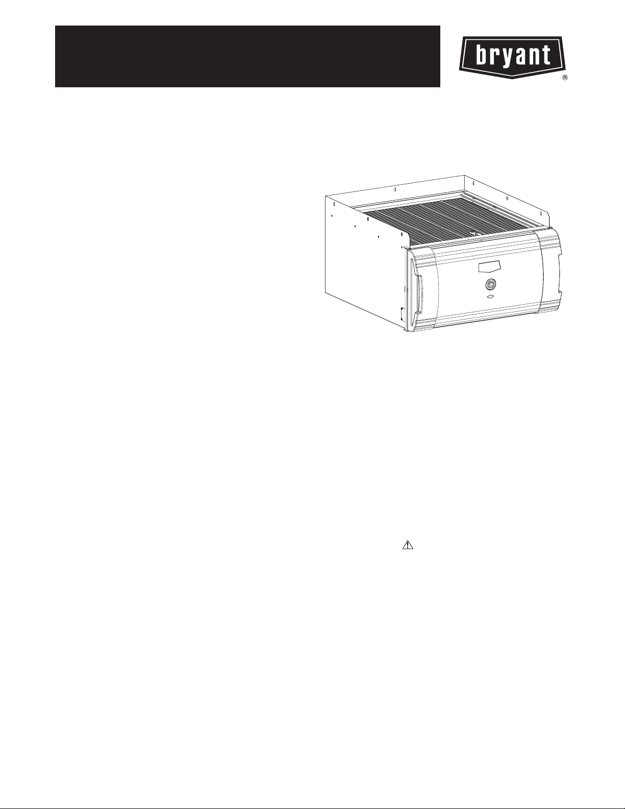
A06367
Fig. 1 --- GAPAB Unit
SAFETY CONSIDERATIONS
. When you see this symbol on the unit
!
CAUTION
PERSONAL INJURY HAZARD
Failure to follow this caution may result in personal injury.
Ozone in concentrations above 0.05 PPM may be
hazardous to health.
Des concentrations d’ozone superieures a 0.05 PPM
peuvent etre nocives pour la sante.
APPLICATION CONSIDERATIONS
The Perfect Airt Air Purifier is designed for use in the return air
duct of a forced air heating, cooling, and ventilation system.
Models GAPABXBB1620, GAPABXBB2020 and
GAPABXBB2420 are specifically designed for use in systems
with a fan coil.
Air Conditioning
The Perfect Airt Air Purifier should be installed in a system so
that all the return air is circulated through the air purifier. It
GAPAB
should be located upstream of the fan coil This will help keep the
fan coil clean and prevent condensation from forming within the
Perfect Airt Air Purifier.
Humidifiers
An evaporative humidifier can be mounted upstream of the
Perfect Airt Air Purifier. It is best to install atomizing
humidifiers downstream of the air purifier because hard water salt
deposits and water droplets may damage the air purifier. If an
atomizing humidifier must be mounted upstream of the Perfect
Airt Air Purifier, it should be mounted as far upstream as
possible (at least 6 ft. recommended), and a standard disposable
furnace filter should be mounted between the humidifier and the
air purifier to trap hard water salt deposits and water droplets.
Transitions
If the return air duct or fan coil openings do not fit the Perfect
Airt Air Purifier cabinet openings, gradual transitions are
recommended to reduce air turbulence and maximize efficiency.
No more than 20 degrees (about 4 in. per running ft.) of
expansion should be used on each side of the transition fitting.
Turning Vanes
If the Perfect Airt Air Purifier is installed adjacent to a 90
degree duct elbow, turning vanes should be added inside duct t o
improve air distribution across the face of the air purifier.
Electrical Power / Air Flow Sensor
The Perfect Airt Air Purifier should only be powered when
airflow is present. This model is designed for use with a fan coil
and is equipped with an air flow sensor which provides power
only when the fan coil blower is operating (See Fig. 2). Perfect
Airt Air Purifier models GAPABXBB1620, GAPABXBB2020,
and GAPABXBB2420 are designed to be powered from a
208/230 VAC power source.
A06387
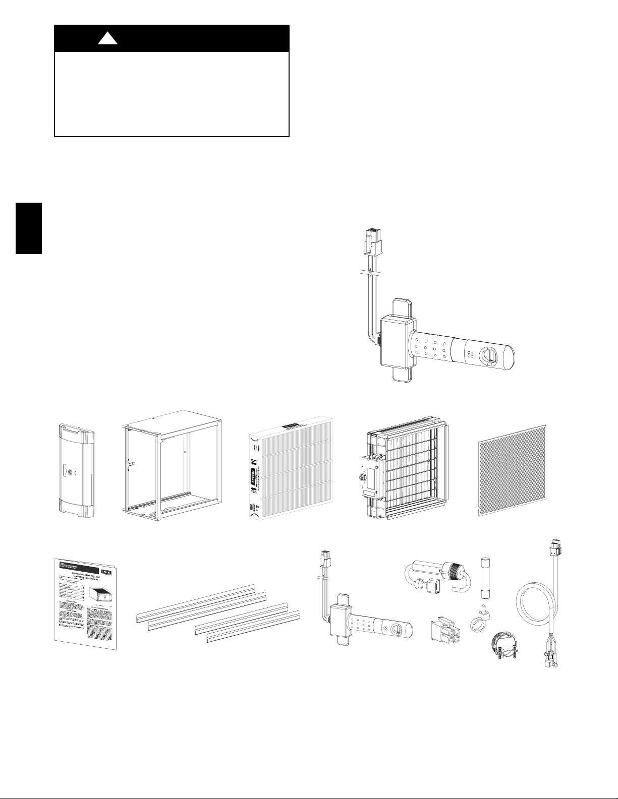
Fig. 2 --- Air Flow Sensor
Door (x1) Cabinet (x1) Enhancement Module (x1) Safety Screen (x1)
Installation Manual Return Duct Adapters:
Long (x2) / Short (x2)
Air Purification Cartridge (x1)
Air Flow Sensor (x1)
(x2)
(x1)
Installation Components
(in bag attached to power cord)
(x3)
(x2)
(x2)
Fig. 3 --- Perfect Airt Air Purifier Components
2
(x1)
A07112
INSTALLATION
Step 1 —Check Perfect Airt Air Purifier Components
!
WARNING
!
CAUTION
CUT HAZARD
Failure to follow this caution may result in personal injury.
Sheet metal parts may have sharp edges or burrs. Use care
and wear appropriate protective clothing and gloves when
handling parts.
a. Carefully remove all items from the box.
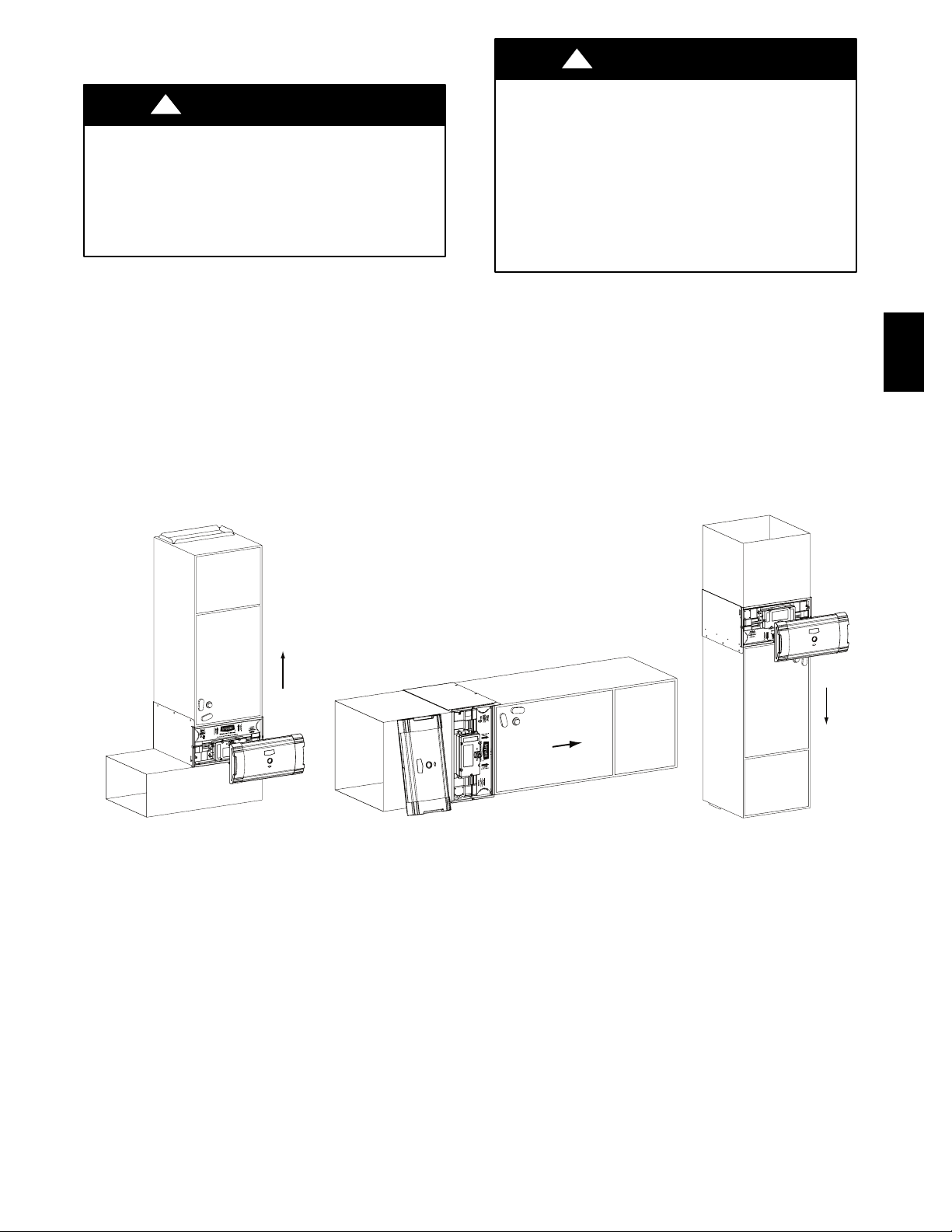
Step 2 —Identify Mounting Location
a. Identify a mounting orientation for the Perfect Airt Air
Purifier in the return air duct (see Fig. 4).
b. Ensure airflow direction through the Perfect Airt Air Pu-
rifier matchesthe arrows on the face of the air purifier cartridge. The Perfect Air Air Purifier or door can be rotated
180_ to accommodate the cabinet orientation.
c. The location of the Perfect Airt Air Purifier should be
readily accessible. Enough room should be provided for
periodic replacement of the air purifier cartridges.
ELECTRICAL SHOCK AND UNIT DAMAGE
HAZARD
Failure to follow this warning could result in personal
injury or death.
Only a trained, experienced service person should install
the Perfect Airt Air Purifier. A thorough check of the
unit installation should be completed before unit
operation. Before performing installation, service or
maintenance operations on unit, turn off all power to
unit. Tag disconnect switch with lockout tag.
GAPAB
Upflow
Airflow
Airflow
Horizontal
Fig. 4 --- Perfect Airt Air Purifier Cabinet Orientation
A06371
Airflow
DownflowA06374
A06517
3
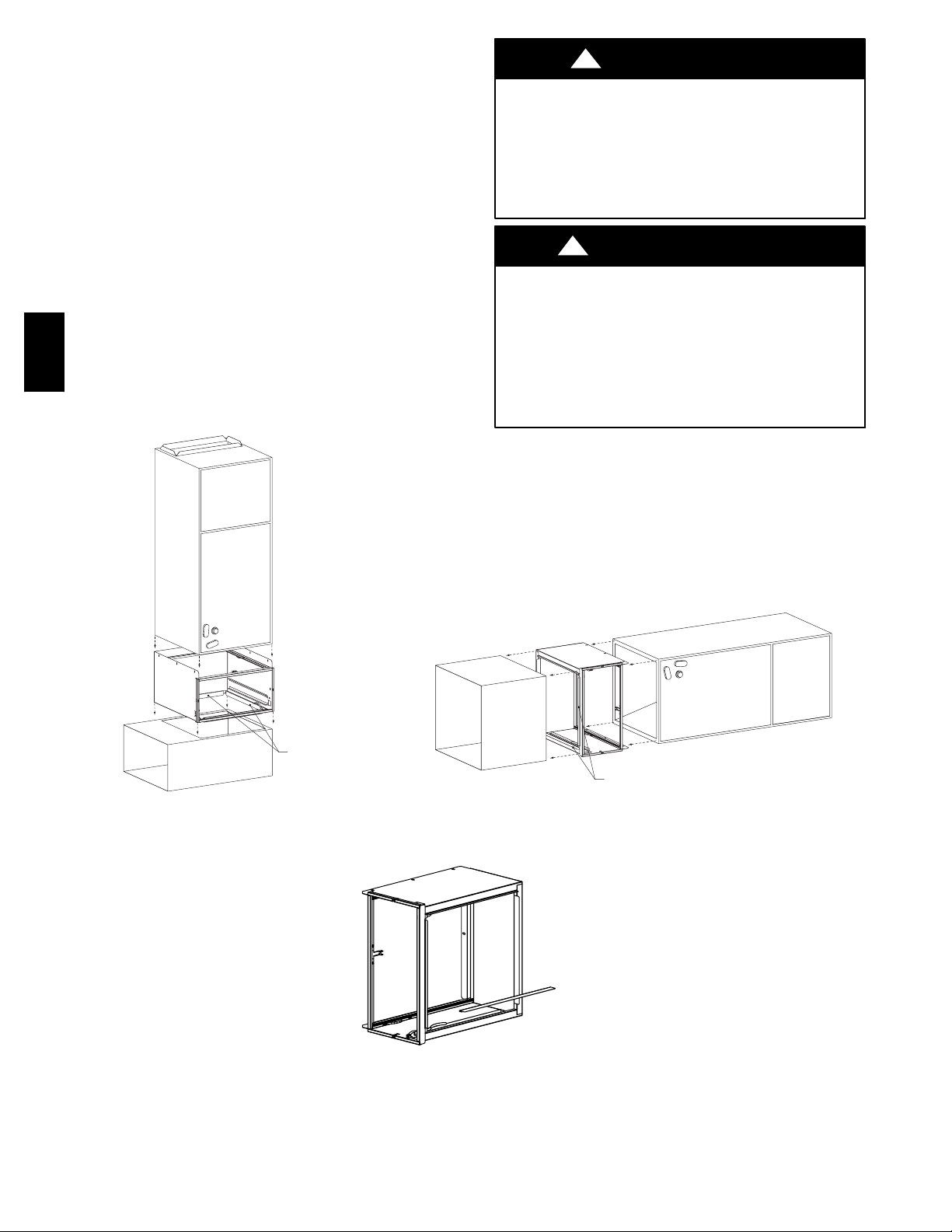
Step 3 —Mount Cabinet
a. Turn off power to the heating and cooling system.
b. Remove the existing fan coil filter and discard. Excessive
system static pre ssure may result if the Perfect Airt Air
Purifier is used with other filtration devices.
c. Remove the air purifier cartridge and enhancement mod-
ule from t he Perfect Airt Air Purifier cabinet.
d. Position the cabinet between the fan coil and return air
duct (see Fig. 4 and 5). A transition duct may be required.
NOTE: The fan coil cabinet screws holding the filter rack should
be used to attach the air purifier cabinet.
e. Gasket tape between the fan coil and the air purifier cabi-
net is already factory installed.
f. Mounting holes are provided for fan coil attachment.
g. Use return duct adapters provided to attach return duct-
work (See Fig. 6).
h. Seal seams with tape or caulking after the Perfect Airt
Air Purifier cabinet has been secured.
GAPAB
!
ELECTRICAL SHOCK AND HIGH VOL TAGE
HAZARD
Failure to follow this warning could result in personal
injury or death.
Before installing or servicing system, always turn off main
power to system. There may be more than 1 disconnect
switch.
!
UNIT DAMAGE HAZARD
Failure to follow this caution may result in equipment
damage.
Cabinets will support a maximum weight of 400 lbs when
installed beneath a vertical fan coil or air--handling unit.
When setting fan coil on cabinet, do not drop it into place.
Position the fan coil correctly on the cabinet to prevent a
corner from slipping down and damaging the cabinet or its
components.
WARNING
CAUTION
Mounting Cabinet Vertical
Fig. 5 --- Mounting Perfect Airt Air Purifier Cabinet for Fan Coils
Return Duct
Adapters (x4)
A06389
Mounting Cabinet Horizontal
A06392
Fig. 6 --- Use of Return Duct Adapters
4
Return Duct
Adapters (x4)
A06388

Step 4 —Wiring
a. Ensure power has been removed from the heating and
cooling system.
b. Turn the Perfect Airt Air Purifier power switch off.
c. Connect the power cord and the flow sensor cord to the
power supply connector and the flow sensor connector
(see Fig. 7 a nd Fig. 8).
NOTE: The power cord can be routed through the opposite side
of the cabinet. Zip ties have been enclosed to secure the power
cord to the side of the power supply.
NOTE: Cable connector and block--off plates will need to be
removed and re--installed if the power cord is re--routed. Screws
on the cable connector clamp should be tightened to 9 in. -- lbs.
torque.
NOTE: The Perfect Airt Air Purifier is to be powered by
208/230Vac/60 Hz.
NOTE: The Perfect Airt Air Purifier should only be powered
when airflow is present. An airflow sensor is factory--installed
(See Fig. 2 and Fig. 11). In order to bypass the airflow sensor,
use the special bypass jumper included in the parts bag. With the
bypass jumper in place, the air purifier will be on at all times
when connected to electrical line power (see Fig. 10).
d. Attach the quick connect terminals to the fused power
connector leads (in parts bag attached to power cord) and
connect to incoming field power. Attach the ground ring
to fan coil chassis ground. (See Fig. 10.)
!
ELECTRICAL SHOCK AND HIGH VOLTAGE
HAZARD
Failure to follow this warning could result in personal injury
or death.
Before installing or servicing system, always turn off main
power to system. There may be more than 1 disconnect
switch.
EQUIPMENT DAMAGE HAZARD
Failure to follow this caution may result in equipment
damage or improper operation.
This unit cannot be powered directly from blower motor
leads. Do not wire directly to blower motor. Wiring to
blower motor will damage power supply and void
warranty.
WARNING
!
CAUTION
GAPAB
Fig. 7 --- Flow Sensor Cable Installed
AIR FLOW SENSOR CABLE OR AIR FLOW
SENSOR BYPASS PLUG MUST BE CONNECTED
TOTHEPOWERSUPPLYINORDERTO
ACTIVATE THE AIR PURIFIER
Fig. 9 --- Airflow Sensor Bypass Plug Installed
A06414
A06413
Fig. 8 --- Power Cord Installed
NOTICE
A06670
5

CABLE CONNECTOR
A
TO SECURE POWER CORD
TO FAN COIL CABINET
GAPAB
AIR PURIFIER
POWER CORD
ir Flow Sensor
FUSED POWER CONNECTOR LEADS
FROM INSTALLATION COMPONENTS
(IN BAG ATTACHED TO POWER CORD)
GROUND:
ATTACH TO FAN COIL
GROUND (CHASSIS)
Fig. 10 --- Fan Coil Chassis Ground
TO FAN COIL FIELD POWER CONNECTION
TO L2 FIELD POWER SUPPLY
5 AMP IN-LINE FUSES
TO L1 FIELD POWER SUPPLY
TO FAN COIL FIELD POWER CONNECTION
A06515
1) Slide flow sensor tabs into support bracket 2) Rotate flow sensor and clip into bracket
Fig. 11 --- Flow Sensor Install
6
A06412

START--UP AND OPERATION
Step 1 —Checking Air Purifier Operation
!
WARNING
ELECTRICAL SHOCK AND HIGH VOLTAGE
HAZARD
Failure to follow this warning could result in personal injury
or death.
Before installing or servicing system, always turn off main
power to system. There may be more than one (1) disconnect
switch.
a. Attach the Perfect Airt Air Purifier door to the cabinet.
A magnet in the door (see Fig. 8) is used to activate a safety switch in the power supply when the door is installed.
The power supply will not energize the air purifier unless
the safety switch is activated.
b. Turn the HVAC system power on and adjust the thermo-
stat or Evolutiont System Control to activate the system
fan.
c. Turn the Perfect Airt Air Purifier power switch to on
position.
d. The power indicator light above the Air Purifier power
switch should illuminate (see Fig. 13).
e. Check to ensure the light goes off when the Perfect Airt
Air Purifier power switch is set to off, when the blower
goes off, or when the HVAC system power is turned off.
NOTE: Upon power--up, the light will come on for
approximately 5 seconds and if no flow is detected, it will go off.
If no air purifier cartridge is detected, the flow sensor will detect
this and turn off after approximately 7 seconds.
Step 2 —Evolution Control
a. When the Perfect Airt AirPurifier isused with an Evolu-
tion Control, the Evolution Control can be configured to
remind the homeowner when it is time to change the Perfect Airt Air Purifier cartridge. This maintenance reminder can be based on either the TrueSenset dirty filter
algorithm or time. Theinstaller should use their discretion
to select the most appropriate option based on the initial
system static pressure.
Step 3 —Maximizing Performance
a. Maximum air purification performance is obtained when
the furnace blower is set for continuous operation on the
thermostat or Evolution Control.
Door Switch Magnet
Power Indicator
A06370
Fig. 13 --- Power Indicator
MAINTENANCE
The Perfect Air t Air Purifier is designed to require minimal
maintenance. Maintenance is limited to the replacement of the
air purification cartridge and inspection/brush c leaning of the
ionization array. Frequency of air purifier cartridge replacement
and cleaning of the ionization array may vary depending on
ductwork design and local environmental conditions.
To replace the air purifier cartridge, complete the following
steps:
Step 1 —Turn the heating and cooling system power off.
!
ELECTRICAL SHOCK AND HIGH VOLTAGE
HAZARD
Failure to follow this warning could result in personal injury
or death.
Before installing or servicing system, always turn off main
power to system. There may be more than one (1) disconnect
switch.
Step 2 —Turn the Perfect Airt Air Purifier switch to the off
position.
Step 3 —Remove the Perfect Airt Air Purifier door.
Step 4 —Slide out the old air purifier cartridge and discard.
Step 5 —Install the new air purifier cartridge.
NOTE: Make sure that the arrows on the air purifier cartridge
point toward the fan coil. This should be in the same
direction as airflow.
Step 6 —Replace the Perfect Airt Air Purifier door.
Step 7 —Turn the Perfect Airt Air Purifier switch to the on
position.
Step 8 —Turn heating and cooling system power on.
WARNING
GAPAB
Fig. 12 --- Door Switch Magnet
A06369
7

At the time of air purifier cartridge replacement, if a
residue is noticed on the tips of the points in the
array, proceed to clean them by completing the
steps:
Step 1 —Turn the heating and cooling system power off.
!
WARNING
ELECTRICAL SHOCK AND HIGH VOLTAGE
HAZARD
Failure to follow this warning could result in personal injury
or death.
Before installing or servicing system, always turn off main
power to system. There may be more than one (1) disconnect
switch.
Step 2 —Turn the Perfect Airt Air Purifier switch to the off
position.
Step 3 —Remove the Perfect Airt Air Purifier door.
GAPAB
Step 4 —Unplug the power cord and flow sensor cable (if
connected) from the enhancement module 9 ( See Fig. 7 and 8)
Step 5 —Slide out the enhancement module assembly and safety
screen.
powdery
ionization
following
!
CUT HAZARD
Failure to follow this caution may result in personal injury.
Sheet metal parts may have sharp edges or burrs. Use care
and wear appropriate protective clothing and gloves when
handling parts.
Step 6 —Slide out the Safety Screen and set aside.
NOTE: Best cleaning tools: 5 inch handle paint brush with 2
inch width (or greater) brush point (synthetic or natural bristle)
(See Fig. 14) or vacuum cleaner with brush attachment.
Step 7 —Gently stroke the ionization pins on the top plane of
each bar with enough brush depth to hit front and back tips of the
points in the ionization array. Use a gentle back and forth
brushing motion to clean any small accumulations from the tips
of the points. If desired, use vacuum cleaner with brush
attachment to gently vacuum the frame and components of
enhancement module.
Step 8 —Reinstall the Safety Screen.
Step 9 —Slide in enhancement module.
Step 10 —Reconnect the power cord and flow sensor cable.
Step 11 — Replace the Perfect Airt Air Purifier Door
Step 12 —Turn the Perfect Airt Air Purifier switch to the on
position.
Step 13 —Turn heating and cooling system power on.
WARNING
POINTS ARE SHARP! BE VERY CAREFUL DURING CLEANING.
Tip of point with residue
Fig. 14 --- Removal of Deposits from Ionization Pins
Tip of point after cleaning
8
30°
A06671

TROUBLESHOOTING
!
CAUTION
SAFETY HAZARD
Failure to follow this caution may result in personal injury
or equipment damage.
The following instructions are for use by qualified
personnel only.
!
WARNING
ELECTRICAL SHOCK AND HIGH VOLTAGE
HAZARD
Failure to follow this warning could result in personal injury
or death.
The following procedures will expose electrical components.
Disconnect power between checks and proceed carefully.
The Perfect Airt Air Purifier is equipped with a power indicator
light located on the door (see Fig. 13). This power indicator light
will illuminate when the Perfect Airt Air Purifier door is
installed, the power switch is in the on position, AND the fan coil
blower is running and airflow is sensed. If the power indicator
light is not illuminated, follow the troubleshooting steps below.
Step 1 —Check that the Perfect Airt Air Purifier door is
installed.
NOTE: A magnet in the door (see Fig. 8) is used to activate a
safety switch in the power supply when the door is installed. The
power supply will not energize the air purifier unless the safety
switch is activated.
Step 2 —Check that the Perfect Airt Air Purifier power switch
is in the on (closed) position.
Step 3 —Confirm that the fan coil blower is operating.
Step 4 —Confirm that 208/230 VAC power is provided. Attach
power supply connector to the air purifier when the fan coil
blower is operating.
NOTE: Even though power is supplied to the Perfect Airt Air
Purifier, it will not turn on unless the airflow sensor senses
airflow or the airflow sensor’s bypass plug is inserted.
Step 5 —Confirm that the airflow sensor cable or airflow sensor
bypass plug is connected to the power supply (See Fig. 7).
Step 6 —If still not functioning, disconnect the airflow sensor
cable and the power cord from the power supply.
Remove the enhancement module from the air purifier cabinet
and inspect the airflow sensor (See Fig. 11).
Confirm the airflow sensor is properly seated in its bracket and
the airflow sensor cable is connected to the back of the sensor.
Replace the enhancement module.
Step 7 —Reconnect the power cord to the power supply and
insert the airflow sensor disable jumper (from parts bag).
If the power indicator light illuminates, then replace the airflow
sensor.
Install the door onto the air purifier and turn the power switch to
the “ON” position.
Step 8 —If all of the above steps are completed and the power
indicator light is still not illuminating, replace the power supply
on the enhancement module. Note that there are no serviceable
parts within the power supply.
GAPAB
9

SPECIFICATIONS AND DIMENSIONS
Table 1—Specifications and Dimensions
Specifications GAPABXBB1620 GAPABXBB2020 GAPABXBB2420
Color Taupe Metallic Taupe Metallic Taupe Metallic
Cabinet Material 20 Ga. Powder Coated Steel 20 Ga. Powder Coated Steel 20 Ga. Powder Coated Steel
Electrical 208/230v/60Hz 208/230v/60Hz 208/230v/60Hz
Maximum Airflow (CFM) 1350 1800 2000
Efficiency Equivalent to MERV 15 Equivalent to MERV 15 Equivalent to MERV 15
Replacement Cartridge GAPCBBAR1620 GAPCBBAR2020 GAPCBBAR2420
Initial Pressure Drop (in w.c.)
(at maximum airflow)
Dimensions GAPABXBB1620 GAPABXBB2020 GAPABXBB2420
GAPAB
A 18--- 1/2 22 25--- 1/2
B 15---1/8 18--- 5/8 22---1/8
C 13---1/8 13---1/8 13---1/8
D 17---5/8 21---1/8 24---5/8
E 19--- 3/4 19 ---3/4 19 ---3/4
F 22 ---1/4 22---1/4 22---1/4
G 11---1/4 11 ---1/4 11---1/4
.22 .25 .22
G
1 3/16"
A DB
3/8" (Typical Top & Bottom)
C E
1 1/2"
Fig. 15 --- Dimensions
1 3/16"
F
1 3/16"
A06368
10

WARRANTY
FOR SERVICE OR REPAIR, FOLLOW THESE STEPS IN ORDER:
FIRST: Contact the installer. You may find their name on the product or in your Homeowner’s Packet. If the installer’s name is not known, call
your builder or home retailer if yours is a new residence.
SECOND: Contact the nearest distributor. (See telephone yellow pages.)
THIRD: Contact:
Bryant Heating and Cooling Systems
Consumer Relations
P.O. Box 4808
Syracuse, New York 13221
Telephone: 1--800--428--4326
Model No. ____________________________________________ Unit Serial No. ______________________________________
Date of Installation _____________________________________ Installed by _________________________________________
Name of Owner _______________________________________ Address of Installation _________________________________
___________________________________________________
PERFECT AIRt AIR PURIFIERS
FIVE--YEAR LIMITED WARRANTY-- ---- Bryant Heating & Cooling Systems (herein after referred to as ‘Company’) warrants this product to be free
from defects in material and workmanship. If a def ect i s found within five years from the date of original installation of the product (whether or not
actual use begins on that date) Company will provide a new or remanufactured part, at Company’ssole option,to replace any defective part, without
charge for the part itself.
This warranty does not include labor or other costs incurred for diagnosing, repairing, removing, installing, shipping, servicing or handling of
either defective parts, or replacement parts, or new units.
WARRANTY CONDITIONS:
1. Warranties apply only to products in their original installation location.
2. Installation, use, care, and maintenance must be normal and in accordance with instructions contained in the Owner’s Manual and Company’s service information.
3. Defective parts must be returned to the distributor through a registered servicing dealer for credit.
4. All work shall be performed during normal working hours.
LIMITATIONS OF WARRANTIES – ALL IMPLIED WARRANTIES AND/OR CONDITIONS (INCLUDING IMPLIED WARRANTIES OR
DITIONS OF MERCHANTABILITY AND FITNESS FOR A PARTICULAR PURPOSE) ARE HEREBY LIMITED IN DURATION TO THE
FOR WHICH THE LIMITED WARRANTY OR CONDITION IS GIVEN AND APPLIES. SOME STATES OR PROVINCES DO NOT ALLOW
ITATIONS ON HOWLONG AN IMPLIED WARRANTYOR CONDITION LASTS, SOTHE ABOVE MAY NOT APPLY TO YOU. THE
WARRANTIES MADE IN THIS WARRANTYARE EXCLUSIVE AND MAY NOT BE ALTERED, ENLARGED, OR CHANGED BY ANY
TOR, DEALER, OR OTHER PERSON, WHATSOEVER
BRYANT WILL NOT BE RESPONSIBLE
1. Normal maintenance as outlined in the installation and servicing instructions or owner’s manual including coil cleaning, filter cleaning and/or
replacement and lubrication.
2. Damage or repairs required as a consequence of faulty installation, misapplication, abuse, impr oper servicing, unauthorized alteration, or improper operation.
3. Failure to startdue tovoltage conditions, blown fuses, open circuit breakers or otherdamages due to the inadequacy or interruption of electrical
service.
4. Damage as a result of floods, winds, fires, lightning, accidents, corrosive environments, or other conditions beyond the control of Company.
5. Parts not supplied or designated by BRYANT, or damages resulting from their use.
6. Company products installed outside the continental U.S.A., A laska, Hawaii, and Canada.
7. Electricity or fuel costs or increases in electricity or fuel costs from any reason whatsoever including additional or unusual use of supplemental
electric heat.
ANY SPECIAL, INDIRECT, OR CONSEQUENTIAL PROPERTY OR COMMERCIAL DAMAGE OF ANY NATURE WHATSOEVER. Some
8.
states do not allow the exclusion of incidental or consequential damages, so the above limitation may not apply to you.
FOR:
.
CON-
PERIOD
LIM-
EXPRESSED
DISTRIBU-
GAPAB
This warranty gives you specific legal rights, and you may also have other rights, which vary from state to state.
Catalog No. 39004DP317
07/06
11

GAPAB
EBryant Heating & Cooling Systems 7310 W. Morris St. Indianapolis, IN 46231 Printed in U.S.A. Edition Date: 02/07
Manufacturer reserves the right to discontinue, or change at any time, specifications or designs without notice and without incurring obligations.
12
Catalog No. IIGAPAB --- 0 --- 2
R e p l a c es : I I G AP A B --- 0 --- 1
 Loading...