

Page 1
180CNV EVOLUTIONREXTREME SERIES
VARIABLE SPEED HEAT PUMP
WITH PURONr REFRIGERANT
(2 -- 5 Ton)
Installation Instructions
NOTE: Read the entire instruction manual before starting the installation.
TABLE OF CONTENTS
PAGE N O .
SAFETY CONSIDERATIONS 1....................
INSTALLATION RECOMMENDATIONS 2..........
INSTALLATION 3--9..............................
Step 1 — Check Equipment and Jobsite 3...........
Step 2 — Install on Solid Pad 3...................
Step 3 — Clearance Requirements 3................
Step 4 — Operating Ambient 4...................
Step 5 — Elevate Unit 4.........................
Step 6 — Making Piping Connections 4............
Step 7 — Make Electrical Connections 5............
Step 8 — Compressor Crankcase Heater 6...........
Step 9 — Install Accessories 6....................
Step 10 — Start--Up 6...........................
Step 11 — System Functions and Seq. Of Operation. 7.
Step 12 — Check Charge 8.......................
Step 13 — Pumpdown 9.........................
MAJOR COMPONENTS 9.........................
TROUBLESHOOTING 9...........................
FINAL CHECKS 15...............................
CARE AND MAINTENANCE 15....................
PURONr REFRIGERANT QUICK REF. GUIDE 15....
Information in these installation instructions pertains only to
180CNV series units.
Indoor Thermostat Control Options
Model
180CNV Yes *
* Requires model SYSTXBBIT W01 ---A, SYSTXBBITC01---A, SYSTXBBTC01---B or newer. Ensure the wall control software has been updated to the latest version available from HVAC Partners.
Evolution
Control
SAFETY CONSIDERAT IONS
Improper installation, adjustment, alteration, service, maintenance,
or use can cause explosion, fire, electrical shock, or other
conditions which may cause death, personal injury, or property
damage. Consult a qualified installer, service agency, or your
distributor or branch for information or assistance. The qualified
installer or agency must use factory--authorized kits or accessories
when modifying this product. Refer to the individual instructions
packaged with the kits or accessories when installing.
Follow all safety codes. Wear safety glasses, protective clothing,
and work gloves. Use quenching cloth for brazing operations.
Have fire extinguisher available. Read these instructions
thoroughly and follow all warnings or cautions included in
literature and attached to the unit. Consult local building codes and
current editions of the National Electrical Code ( NEC ) NFPA 70.
In Canada, refer to current editions of the Canadian electrical code
CSA 22.1.
Recognize safety information. This is the safety--alert symbol
When you see this symbol on the unit and in instructions or
manuals, be alert to the potential for personal injury. Understand
these signal words; DANGER, WARNING, and CAUTION. These
words are used with the safety--alert symbol. DANGER identifies
the most serious hazards which will result in severe personal injury
or death. WARNING signifies hazards which could result in
personal injury or death. CAUTION is used to identify unsafe
practices which would result in minor personal injury or product
and property damage. NOTE is used to highlight suggestions
which will result in enhanced installation, reliability, or operation.
!
!
!
CAUTION
CUT HAZARD
Failure to follow this caution may result in personal injury.
Sheet metal parts may have sharp edges or burrs. Use care and
wear appropriate protective clothing and gloves when
handling parts.
Page 2
!
WARNING
EXPLOSION HAZARD
Failure to follow this warning could
result in death, serious personal injury,
and/or property damage.
Never use air or gases containing
oxygen for leak testing or operating
refrigerant compressors. Pressurized
mixtures of air or gases containing
oxygen can lead to an explosion.
!
ELECTRICAL SHOCK HAZARD
Failure to follow this warning could result in personal
injury or death.
Before installing, modifying, or servicing system, main
electrical disconnect switch must be in the OFF position.
There may be more than 1 disconnect switch. Lock out and
tag switch with a suitable warning label.
ELECTRICAL HAZARD -- HIGH VOLTAGE!
Failure to follow this warning could result in personal injury
or death.
Electrical components may hold charge. DO NOT remove
control box cover for 2 minutes after power has been
removed from unit.
PRIOR TO TOUCHING ELECTRICAL COMPONENTS:
Verify zero (0)voltage at inverter connections shown on
inverter cover.
WARNING
!
WARNING
Inverter Cover
IMPORTANT: The inverter cover should NEVER be removed.
The inverter is not field serviceable. A replacement cover is
provided with a replacement inverter.
!
WARNING
INSTALLATION RECOMMENDATIONS
In some cases noise in the living area has been traced to gas
pulsations from improper installation of equipment.
1. Locate unit away from windows, patios, decks, etc. where
unit operation sound may disturb customer.
2. In noise sensitive applications (such as bedrooms), when a
lineset is mounted to ceiling joists or floor joists, the outdoor unit must be located at least 10 ft (3.05 m) away. If
this is not possible, create a line set configuration with
enough bends to provide 10 ft (3.05 m) of total line set
length outside the dwelling
3. Ensure that vapor and liquid tube diameters are appropriate
for unit capacity.
4. Run refrigerant tubes as directly as possible by avoiding unnecessary turns and bends.
5. Leave some slack between structure and unit to absorb vibration.
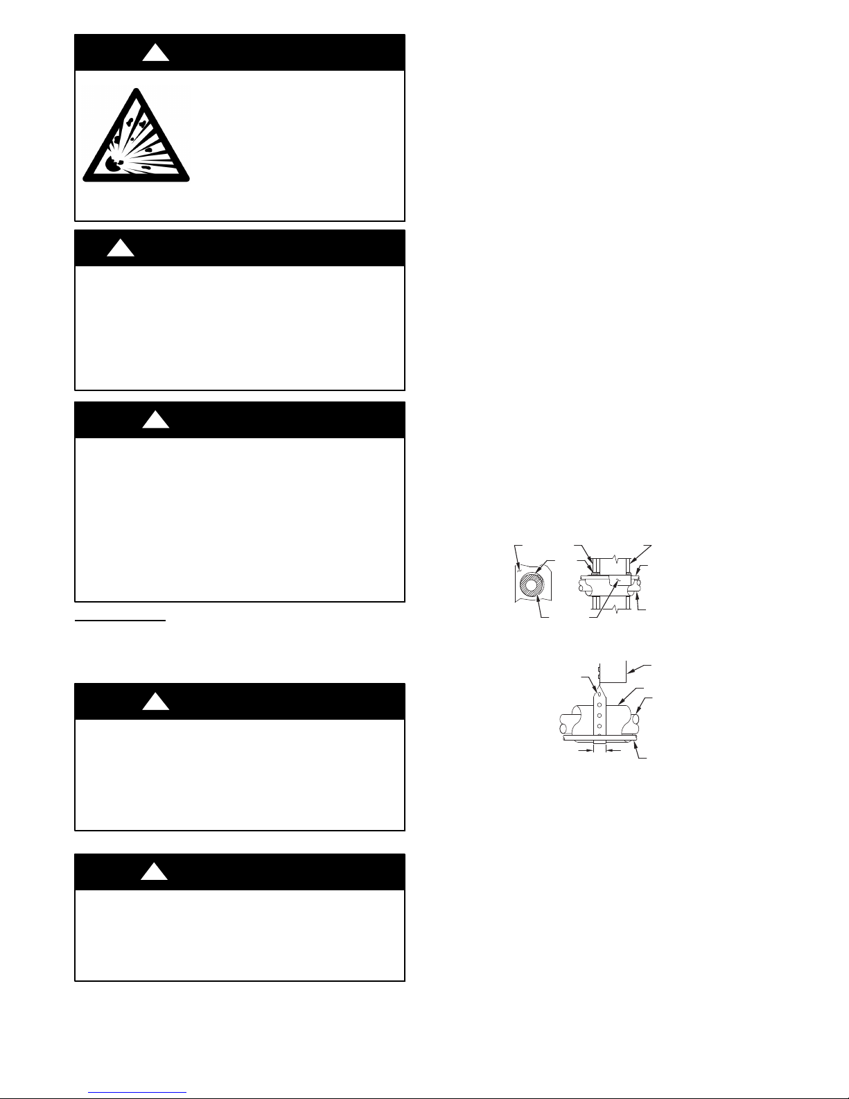
6. When passing refrigerant tubes through the wall, seal opening with RTV or other pliable silicon--based caulk (see Fig.
1).
7. Avoid direct tubing contact with water pipes, duct work,
floor joists, wall studs, floors, and walls.
8. Do not suspend refrigerant tubing from joists and studs with
a rigid wire or strap which comes in direct contact with tubing (see Fig. 1).
9. Ensure that tubing insulation is pliable and completely surrounds vapor tube.
10. When necessary, use hanger straps which are 1 in. wide and
conform to shape of tubing insulation. (See Fig. 1.)
11. Isolate hanger straps from insulation by using metal sleeves
bent to conform to shape of insulation.
OUTDOOR WALL INDOOR WALL
CAULK
INSULATION
HANGER STRAP
(AROUND SUCTION
TUBE ONLY)
THROUGH THE WALL
LIQUID TUBE
SUCTION TUBE
JOIST
INSULATION
SUCTION TUBE
UNIT OPERATION AND SAFETY HAZARD
Failure to follow this warning could result in personal injury
or equipment damage.
PuronR refrigerant systems operate at higher pressures than
standard R--22 systems. Do not use R--22 service equipment
or components on PuronR refrigerant equipment.
!
CAUTION
EQUIPMENT DAMAGE HAZARD
Failure to follow this caution may result in equipment damage.
If proper lineset routing techniques are not followed, variable
speed systems can be susceptible to lineset transmitted noise
inside the dwelling and, in extreme cases, tubing breakage.
1” (25.4 mm)
MIN
SUSPENSION
Fig. 1 -- Connecting Tubing Installation
2
LIQUID TUBE
A07588
Page 3
The outdoor unit contains the correct amount of refrigerant charge
for operation with AHRI rated and factory--approved smallest
indoor unit when connected by 15 ft (4.57 m) of field--supplied or
factory accessory tubing.
Adjust refrigerant charge by adding or removing the charge
to/from the unit depending on lineset length and indoor unit as
calculated and displayed on the wall control. The wall control
calculates required charge adjustment and total system charge
required. For proper unit operation, check refrigerant charge using
charging information in the Check Charge section of this
instruction.
IMPORTANT: Liquid-- line size is 3/8--in. OD for all 180CNV
applications including long line applications.
IMPORTANT: Always install the factory--supplied liquid--line
filter drier. Obtain replacement filter driers from your distributor or
branch.
INSTALLATION
IMPORTANT: Effective January 1, 2015, all split system and
packaged air conditioners must be installed pursuant to applicable
regional efficiency standards issued by the Department of Energy.
Specifications for this unit in residential new construction market
require the outdoor unit, indoor unit (including metering device),
refrigerant tubing sets, and filter drier listed in pre-- sale literature.
There can be no deviation. Consult the Service Manual – Air
Conditioners and Air Conditioners Using Puron Refrigerant to
obtain required unit changes for specific applications and for R--22
retrofit.
Step 1 — Check Equipment and Job Site
Unpack Unit
Move to final location. Remove carton taking care not to damage
unit.
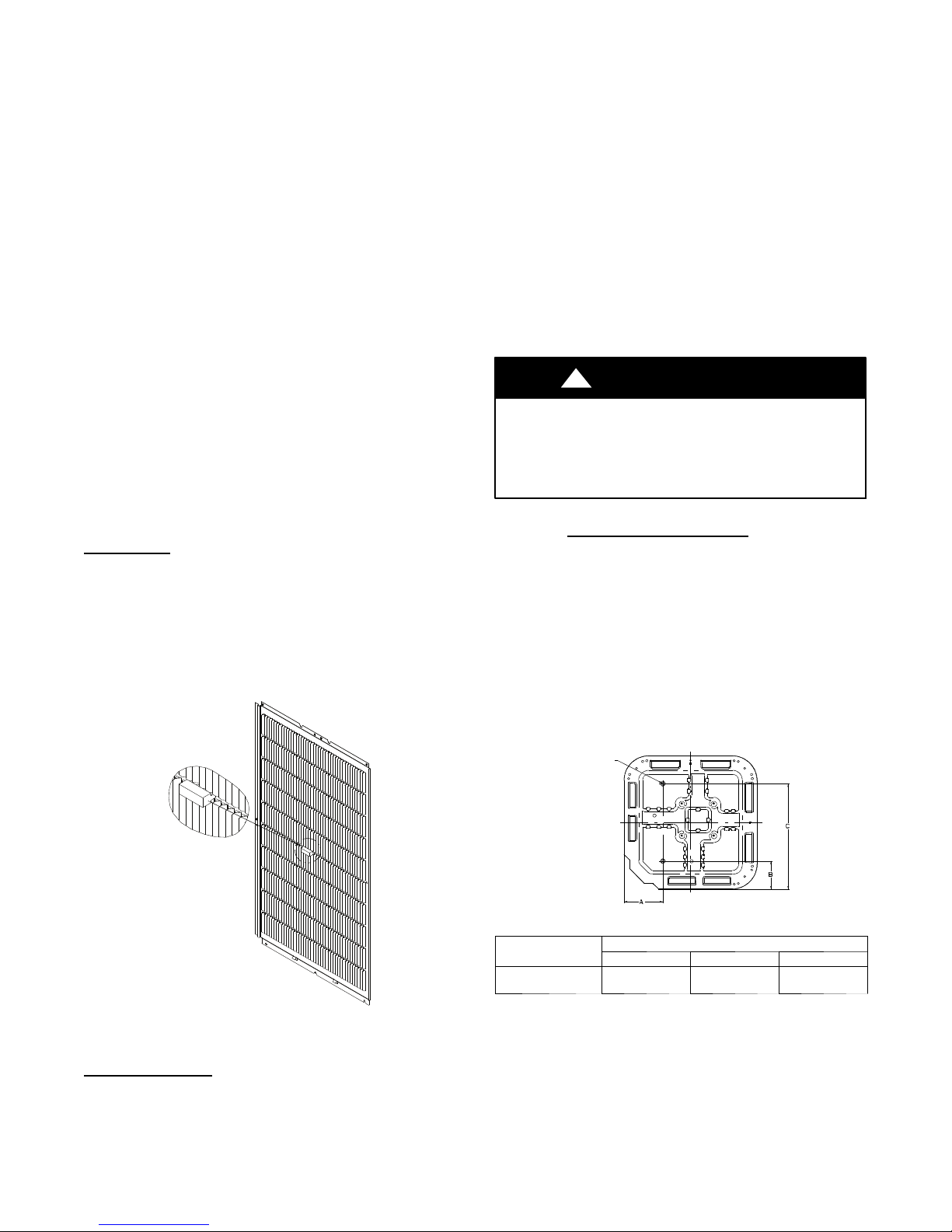
This unit employs one louver spacer on each of the four sides to
prevent louver movement during operation. The louver spacers are
trapped between the coil surface and louver at the approximate
center of each side (See Fig. 2). This louver spacer should be
present and, if dislodged during shipment, must be reinstalled
before unit is placed into operation.
Step 2 — Install on a Solid, Level Mounting Pad
If conditions or local codes require the unit be attached to pad, tie
down bolts should be used and fastened through knockouts
provided in unit base pan. Refer to unit mounting pattern in Fig. 3
to determine base pan size and knockout hole location.
For hurricane tie downs, contact distributor for details and PE
(Professional Engineer) Certification, if required.
On rooftop applications, mount on level platform or frame. Place
unit above a load--bearing wall and isolate unit and tubing set from
structure. Arrange supporting members to adequately support unit
and minimize transmission of vibration to building. Consult local
codes governing rooftop applications.
Roof mounted units exposed to winds above 5 mph may require
wind baffles. Consult the Service Manual -- Residential Split
System Air Conditioners and Air Conditioners Using Puron
Refrigerant for wind baffle construction.
NOTE: Unit must be level to within 2 (3/8 in./ft,9.5 mm/m.)
per compressor manufacturer specifications.
!
CAUTION
UNIT OPERATION HAZARD
Failure to follow this caution may result in equipment
damage or improper operation.
Locate the unit in such a way that it is stable in all
circumstances including adverse weather conditions.
Step 3 — Clearance Requirements
When installing, allow sufficient space for airflow clearance,
wiring, refrigerant piping, and service. Allow 24 in. (609.6 mm)
clearance to service end of unit and 48 in. (1219.2 mm) (above
unit. For proper airflow, a 6 --in. (152.4 mm) clearance on 1 side of
unit and 12--in. (304.8 mm) on all remaining sides must be
maintained. Maintain a distance of 24 in. (609.6 mm) between
units. Position so water, snow, or ice from roof or eaves cannot fall
directly on unit.
On rooftop applications, locate unit at least 6 in. (152.4 mm) above
roof surface.
3/8---in. (9.53 mm) Dia.
Tiedown Knockouts in
Basepan(2) Places
Fig. 2 -- Louver Spacer Location
Inspect Equipment
File claim with shipping company prior to installation if shipment
is damaged or incomplete. Locate unit rating plate on unit corner
panel. It contains information needed to properly install unit.
Check rating plate to be sure unit matches job specifications.
A11380a
UNIT BASE PAN
Dimension in. (mm)
35 X 35
(889 X 889)
Fig. 3 -- Tiedown Knockout Locations
3
View From Top
A05177
TIEDOWN KNOCKOUT LOCATIONS in. (mm)
A B C
9–1/8 (231.8) 6–9/16 (166.7) 28–7/16 (722.3)
Page 4

Step 4 — Operating Ambient
The minimum outdoor operating ambient in cooling mode is 55_F
(13_C) without low ambient cooling enabled, and the maximum
outdoor operating ambient in cooling mode is 125_F(52_C).
With Low Ambient Cooling enabled, the minimum outdoor
operating ambient in cooling mode is 0_F(--18_C).
Step 5 — Elevate Unit
Elevate unit per local climate and code requirements to provide
clearance above estimated snowfall level and ensure adequate
drainage of unit for units installed for low ambient cooling
operation..
!
CAUTION
UNIT DAMAGE HAZARD
Failure to follow this caution may result in equipment
damage or improper operation.
Do not leave system open to atmosphere any longer than
minimum required for installation. POE oil in compressor is
extremely susceptible to moisture absorption. Always keep
ends of tubing sealed during installation.
!
CAUTION
UNIT OPERATION HAZARD
Failure to follow this caution may result in equipment
damage or improper operation.
Do not allow water and/or ice to build up in base pan.
!
UNIT DAMAGE HAZARD
Failure to follow this caution may result in equipment
damage or improper operation.
If ANY refrigerant tubing is buried, provide a 6 in. (152.4
CAUTION
mm) vertical rise at service valve. Refrigerant tubing lengths
up to 36 in. (914.4 mm) may be buried without further
Step 6 — Make Piping Connections
special consideration. Do not bury lines longer than 36 in.
(914.4 mm).
!
PERSONAL INJURY AND UNIT DAMAGE
HAZARD
Failure to follow this warning could result in personal injury or
death.
Relieve pressure and recover all refrigerant before system
repair or final unit disposal. Use all service ports and open all
flow--control devices, including solenoid valves.
WARNING
Outdoor units may be connected to indoor section using accessory
tubing package or field--supplied refrigerant grade tubing of correct
size and condition. For tubing requirements beyond 80 ft. (24.38
m), substantial capacity and performance losses can occur. Follow
the pipe sizing recommendations in the 180CNV Product data to
manage these losses.
Refer to Table 1 for field tubing diameters. Refer to Table 2 for
accessory requirements.
Ta ble 1 – Refrigerant Connections and Recommended Liquid and Vapor Tube Diameters (in.)
LIQUID VAPOR*
UNIT SIZE
180CNV024
180CNV036
180CNV048
180CNV060
* Units are rated with 25 ft. (7.6 m) of lineset. See Product Data sheet for performance data when using different size and length line sets.
Notes:
1. Do not apply capillary tube indoor coils to these units.
2. For Tubing Set lengths between 80 and 200 ft. (24.38 and 60.96 m) horizontal and / or greater than 20 ft. ( 6.1 m) vertical differential, an accessory Liquid Line
Solenoid must be installed.
Connection
Diameter
3/8 3/8 7/8 7/8 5/8
3/8 3/8 7/8 7/8 5/8
3/8 3/8 7/8 1 --- 1 / 8 3/4
3/8 3/8 7/8 1 --- 1 / 8 3/4
Tube
Diameter
Connection
Diameter
Max (Rated)
Diameter
Minimum Tube
Diameter
REQUIRED FOR
ACCESSORY
Crankcase Heater Standard
Evaporator Freeze Protection Standard with Evolution Con trol No No No
Low--- Ambient Control Standard with Evolution Control No No No
Puron Refrigerant Balance Port
H a r d --- S h u t O f f T X V
Support Feet Recommended No Recommended No
Winter Start Control Standard with Evolution Control Standard with Evolution Control
EMI Kit No No No Ye s
* For tubing set lengths between 80 and 200 ft. (24.38 and 60.96 m) horizontal or 20 ft. (6.10 m) vertical differential (total equivalent length), an accessory
Liquid Line Solenoid must be installed.
{ Required on all indoor units. Standard on all new Puron refrigerant fan coils and furnace coils.
Standard = Standard for all new Puron refrigerant fan coils and furnace coils.
L O W --- A M B I E N T C O O L I N G
APPLICATIONS
(Below 55F/12.8_C)
Ye s {
Table 2 – Accessory Usage
REQUIRED FOR LONG LINE
APPLICATIONS*
(Over 80 ft/24.38 m)
Standard
Ye s {
4
REQUIRED FOR SEA
COAST APPLICATIONS
(Within 2 miles/3.22 km)
Standard Standard
Ye s { Ye s {
Standard with Evolution
Control
Installations with Radio
Frequency Interfe rence
Concerns in the Range
of2to30MHZ
Standard with Evolution
Control
Page 5
Outdoor Unit Connected to Factory--Approved Indoor
Unit
Outdoor unit contains correct system refrigerant charge for
operation with factory--approved, AHRI--rated smallest indoor unit
when connected by 15 ft. (4.57 m) of field--supplied or
factory--accessory tubing, and factory --supplied filter drier. Check
refrigerant charge for maximum efficiency.
NOTE: If the indoor furnace coil width is more than the furnace
casing width, refer to the indoor coil Installation Instructions for
transition requirements.
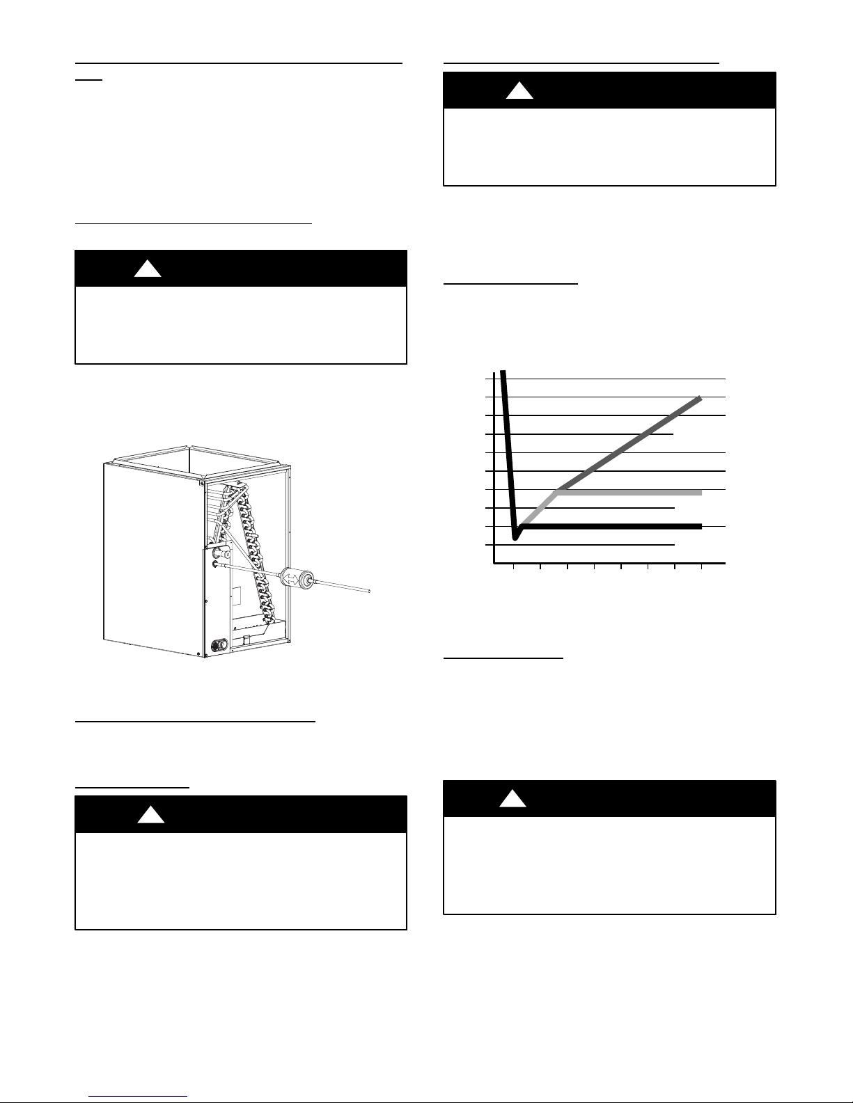
Install Liquid--Line Filter Drier Indoor
Refer to Fig. 4 and install filter drier as follows:
!
UNIT DAMAGE HAZARD
Failure to follow this caution may result in unit damage or
improper operation.
Installation of filter drier in liquid line is required.
1. Braze 5--in. (127 mm) liquid tube to the indoor coil.
2. Wrap filter drier with damp cloth.
3. Braze filter drier to above 5--in. (127 mm) liquid tube.
4. Connect and braze liquid refrigerant tube to the filter drier.
CAUTION
Evacuate Refrigerant Tubing and Indoor Coil
!
UNIT DAMAGE HAZARD
Failure to follow this caution may result in equipment
damage or improper operation.
Never use the system compressor as a vacuum pump.
Refrigerant tubes and indoor coil should be evacuated using the
recommended deep vacuum method of 500 microns. The alternate
triple evacuation method may be used. See Service Manual for
triple evacuation method. Always break a vacuum with dry
nitrogen prior to opening the refrigerant system for servicing.
CAUTION
Deep Vacuum Method
The deep vacuum method requires a vacuum pump capable of
pulling a vacuum of 500 microns and a vacuum gauge capable of
accurately measuring this vacuum depth. The deep vacuum method
is the most positive way of assuring a system is free of air and
liquid water. (See Fig. 5)
5000
4500
4000
3500
3000
2500
2000
MICRONS
1500
1000
500
LEAK IN
SYSTEM
VACUUM TIGHT
TOO WET
TIGHT
DRY SYSTEM
A05227
Fig. 4 -- Liquid-- Line Filter Drier
Refrigerant Tubing connection Outdoor
Connect vapor tube to fitting on outdoor unit vapor service valves
and connect the liquid tube to fitting on outdoor unit liquid service
valve. See T able 1 for allowable sizes.
Sweat Connections
!
UNIT DAMAGE HAZARD
Failure to follow this caution may result in equipment
damage or improper operation.
S Use a brazing shield
S Wrap service valves with wet cloth or heat sink material.
Use refrigerant grade tubing. Service valves are closed from factory
and ready for brazing. After wrapping service valve with a wet
cloth, braze sweat connections using industry accepted methods
and materials. Consult local code requirements. Refrigerant tubing
and indoor coil are now ready for leak testing. This check should
include all field and factory joints.
CAUTION
01234567
MINUTES
Fig. 5 -- Deep V acuum Graph
A95424
A95424
Final Tubing Check
IMPORTANT: Check to be certain factory tubing on both indoor
and outdoor unit has not shifted during shipment. Ensure tubes are
not rubbing against each other or any sheet metal. Pay close
attention to feeder tubes, making sure wire ties on feeder tubes are
secure and tight.
Step 7 — Make Electrical Connections
!
ELECTRICAL SHOCK HAZARD
Failure to follow this warning could result in personal
injury or death.
Do not supply power to unit with compressor terminal box
cover removed.
Be sure field wiring complies with local and national fire, safety,
and electrical codes, and voltage to system is within limits shown
on unit rating plate. Contact local power company for correction of
improper voltage. See unit rating plate for recommended circuit
protection device.
NOTE: Operation of unit on improper line voltage constitutes
abuse and could affect unit reliability. See unit rating plate. Do not
WARNING
5
Page 6
install unit in system where voltage may fluctuate above or below
permissible limits.
NOTE: Use copper wire only between disconnect switch and unit.
NOTE: Install branch circuit disconnect of adequate size per NEC
to handle unit starting current. Locate disconnect within sight from
and readily accessible from unit, per Section 440--14 of NEC.
Route Ground and Power Wires
Remove access panel to gain access to unit wiring. Extend wires
from disconnect through power wiring hole provided and into unit
control box.
!
ELECTRICAL SHOCK HAZARD
Failure to follow this warning could result in personal injury
or death.
The unit cabinet must have an uninterrupted or unbroken
ground to minimize personal injury if an electrical fault
should occur. The ground may consist of electrical wire or
metal conduit when installed in accordance with existing
electrical codes.
WARNING
Connect Ground and Power Wires
Connect ground wire to ground connection in control box for
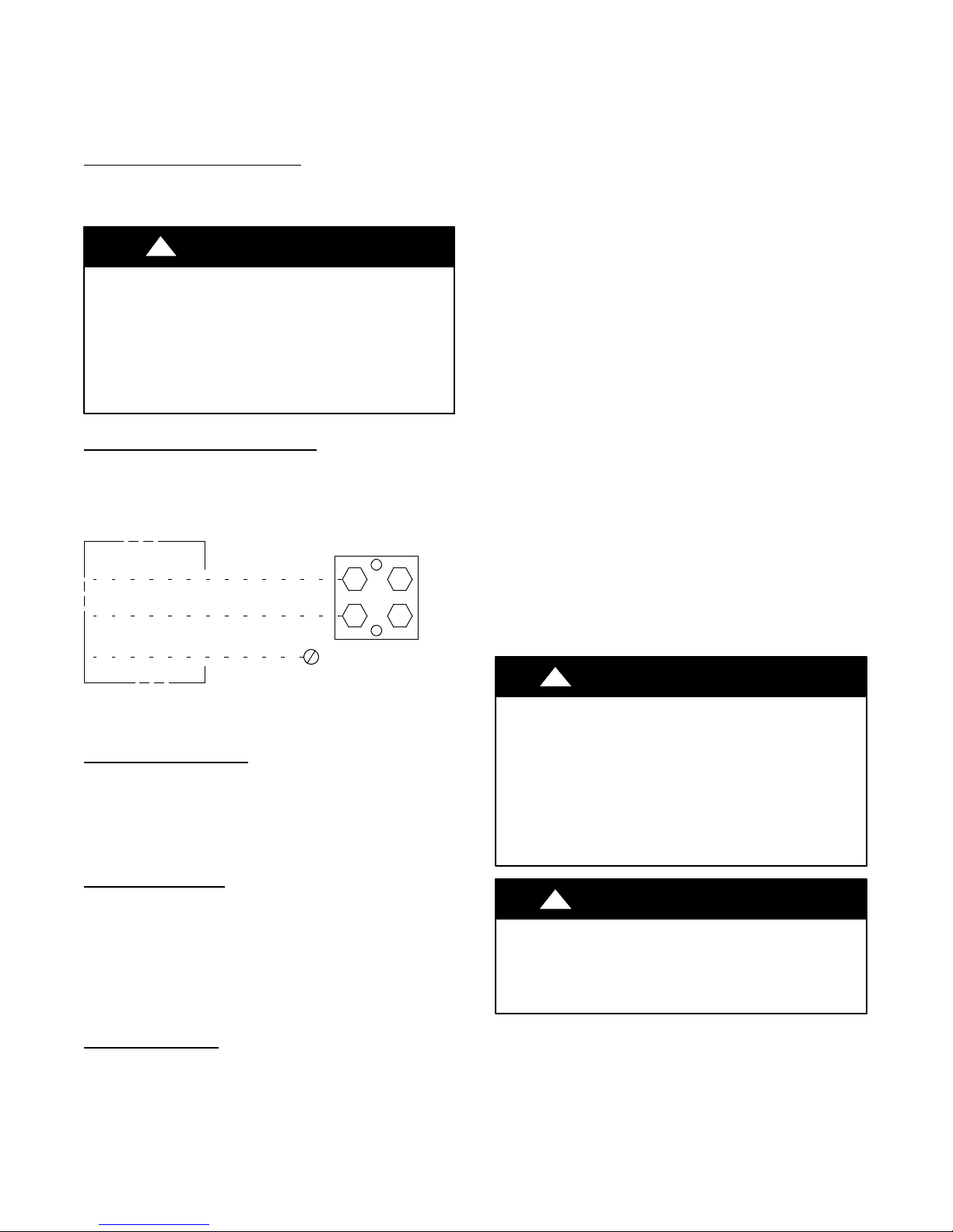
safety. Connect power wiring to contactor as shown in Fig. 6.
DISCONNECT
PER N. E. C. AND/OR
LOCAL CODES
CONTACTOR
FIELD POWER
WIRING
FIELD GROUND
WIRING
Fig. 6 -- Line Power Connections
GROUND
LUG
A91056
Connect Control Wiring
Connect to Evolution connections. Only two wires (AB) to
Evolution capable indoor unit (furnace or fan coil) is required.
Typical 4 wire (ABCD) may be connected (see Fig. 14).
IMPORTANT: This system requires the power supply to the
outdoor unit, and the indoor unit, for the wall control to
communicate with the outdoor unit.
General Information
Use No. 18 AWG or larger color--coded, insulated (35C
minimum) wire for low voltage control wires.
All wiring must be NEC Class 2 and must be separated from
incoming power leads.
Use furnace transformer, fan coil transformer, or accessory
transformer for control power requirement of system accessories
external to the OD unit. The outdoor unit has its own transformer
power.
Final Wiring Check
IMPORTANT: Check factory wiring and field wire connections to
ensure terminations are secured properly. Check wire routing to
ensure wires are not in contact with tubing, sheet metal, etc.
Step 8 — Compressor Crankcase Heater
This compressor has an internal crankcase heater. Furnish power
to the unit a minimum of 24 hr before starting the unit for the first
time.
To furnish power to heater only, set thermostat to OFF and close
electrical disconnect to outdoor unit.
Power is not required to the indoor unit or wall control for proper
operation of heater. Crankcase heater will however be intelligently
energized as needed between operations, and otherwise even when
the wall control and indoor unit is not installed, as long as there is
power to the outdoor unit even if the indoor unit and wall control
are not yet installed.
Airflow Setup for Evolution Control Furnace or
FE Fan Coil (communicating)
This system can only be installed with Evolution--capable indoor
and Evolution wall control with the latest version software. When
using an Evolution wall control, airflow is automatically selected
based on equipment size. The user has the option of selecting
Comfort, Efficiency and Max airflow for Heating and/or Cooling
modes. These should be selected based on balance between the
homeowner’s comfort and energy consumption expectations. See
wall control Installation Instructions for additional available
adjustments.
Due to using a communicating control with the fan coil or the
furnace, dip switch adjustments are not necessary. The outdoor
unit configuration and the indoor airflows are determined by
communicating control setup.
Step 9 — Install Accessories
There are no refrigeration circuit or electrical accessories required
or available for installation within the unit. External to the unit, the
same accessories such as support feet, snow rack, wind baffle etc.,
are available on other Bryant units can also be used on this line of
product. Refer to the individual Installation Instructions packaged
with kits or accessories when installing.
Step 10 — Start--Up
!
UNIT OPERATION AND SAFETY HAZARD
Failure to follow this caution may result in minor personal
injury, equipment damage or improper operation.
Observe the following:
1. Do not overcharge system with refrigerant.
2. Do not operate unit in a vacuum or at negative pressure.
3. Do not disable low pressure switch
4. Dome temperatures may be hot.
!
PERSONAL INJURY HAZARD
Failure to follow this caution may result in personal injury.
Wear safety glasses, protective clothing, and gloves when
handling refrigerant.
CAUTION
CAUTION
6
Page 7
!
ENVIRONMENTAL HAZARD
Failure to follow this caution may result in environmental
damage.
Federal regulations require that you do not vent
refrigerant to the atmosphere. Recover during system
repair or final unit disposal.
CAUTION
Follow these steps to properly start up the system:
1. After system is evacuated, close the disconnects to energize
the ID and OD units to assess the user interface (UI), Keep
system in off mode. Under the Advanced function menu,
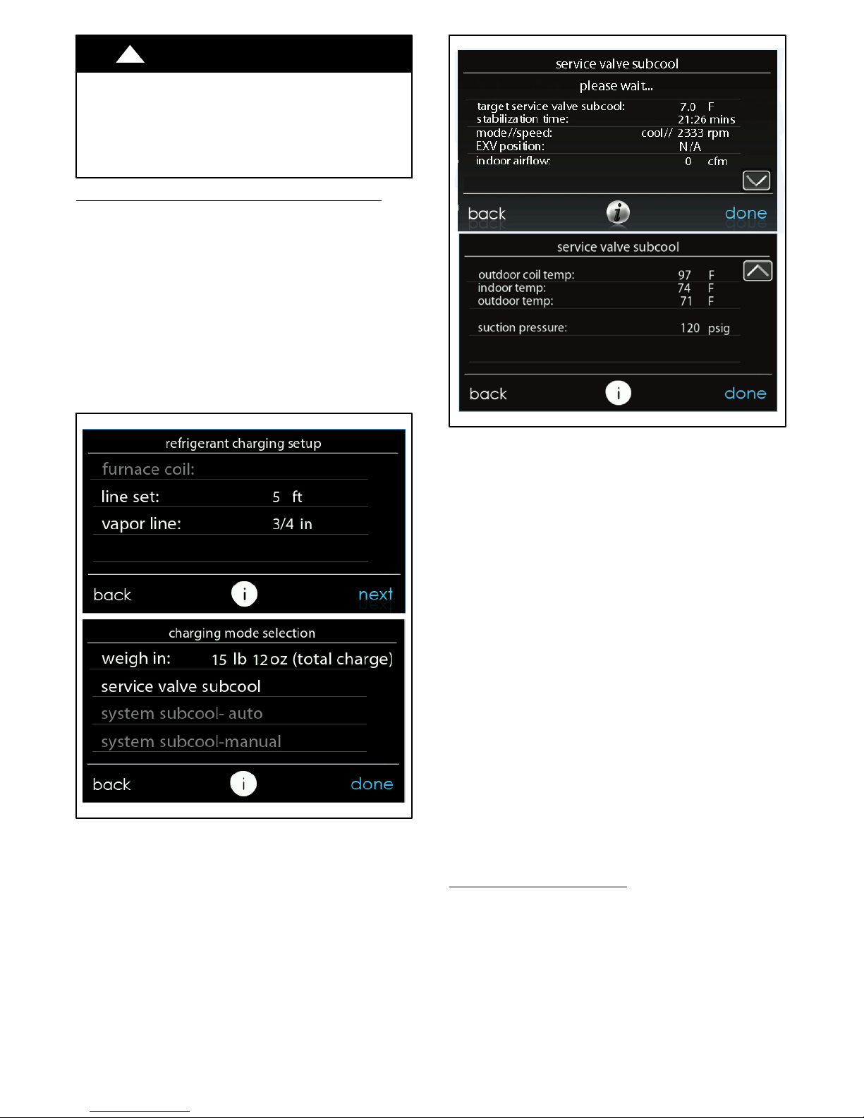
assess the REQUIRED CHARGE CALCULATION screen.
Enter the lineset length and vapor tube diameter. The wall
control will now display the required charge adjustment
(see Fig. 7) for the lineset and an adjustment for a large indoor coil if recognized as such by the wall control.
2. Add or remove the required charge adjustment for lineset
length to liquid service valve.
Note: If lineset is less than 15 feet (--9.4_C), charge re-
moval may be necessary.
3. Fully open liquid and vapor service valves.
Fig. 7 -- Required Charge Adjustment
A170295
Calculated in wall control
4. Set wall control to operate cooling in CHARGING mode
(see Fig.7). Charging mode operates system compressor
speed and fan speeds to proper conditions to check the refrigerant charge.
NOTE: Do not check charge in a mode other than CHARGING.
5. Select service valve subcool.
6. Wait for the specified stabilization time, depending on lineset length. Then Compare measured subcooling at liquid
line service valve to target service valve subcool as shown
on CHARGING screens (see Fig. 8).
Fig. 8 -- Liquid Line Subcooling Target
A170296
Step 11 — System Functions And Sequence Of
Operation
The 180CNV models utilize an Evolution communicating wall
control. With a call for cooling, the outdoor fan and compressor are
energized to run at lowest cooling demand. If this does not satisfy
cooling demand, the system will ramp up in stages until it satisfies
the demand. After coping with the higher demand, the unit returns
to lower capacity operation until the demand is satisfied or until an
increase in demand.
When all demand is satisfied, the compressor will shut off. As the
unit operates at lower capacity, system vapor (suction) pressure will
be higher than it is during a standard single--stage system operation
or during a higher capacity operation.
When the outdoor ambient is more the 100_F (37.8_C), the
outdoor fan will continue to run for one minute after compressor
shuts off. This reduces pressure differential for easier starting in
the next cycle.
The conventional thermostat input is designed to work for
emergency operation only. Connections are Y, and C. The system
will only operate at maximum capacity.
The wall control displays the operation mode and fault codes as
specified in the troubleshooting section. See Table 7 for codes and
definitions.
NOTE: Only one code will be displayed on the outdoor unit
control board (the most recent, with the highest priority). The
latest codes are stored and can be access via the wall control.
Crankcase Heater Operation
This unit has an internal crankcase heater that will be energized
during the off cycle and is intelligently demanded by the system to
prevent the compressor from being the coldest part of the system
thus enhancing the reliability. The crankcase heater will function
as needed any time the outdoor unit is powered. The indoor unit
and UI do not need to be installed for the crankcase heater to
operate properly.
NOTE: Contactor may close intermittently without the unit
starting. This is done to determine whether the control needs to
energize the crankcase heater. Closing the contactor powers the
inverter and allows the system to check compressor temperature.
7
Page 8
Outdoor Fan Motor Operation
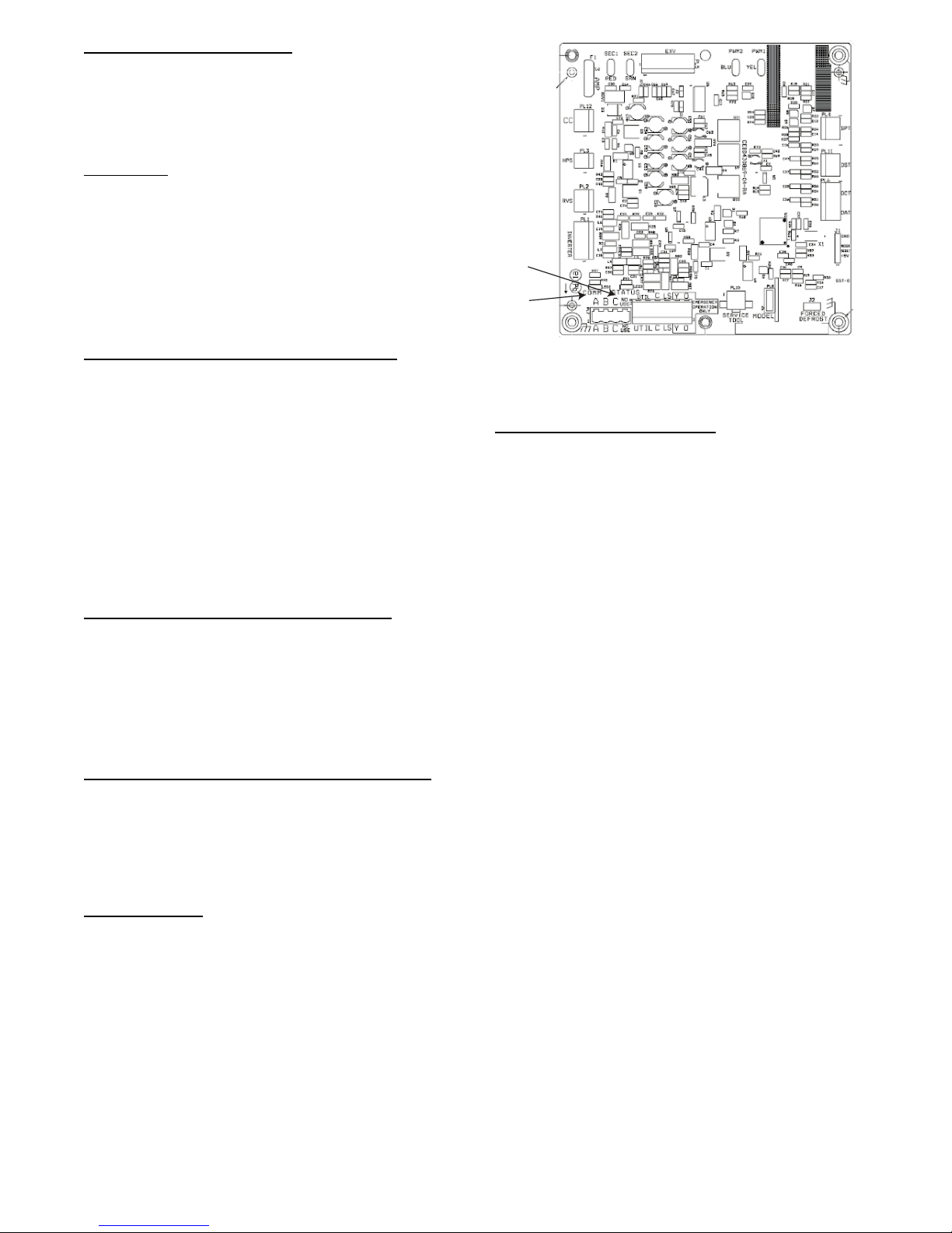
The outdoor unit control (Fig. 9) energizes outdoor fan anytime
compressor is operating as needed during low--ambient cooling
operation. The outdoor fan remains energized if a pressure switch
opens or compressor scroll over temperature should occur. This
OD fan is an ECM motor which operates at varying speeds
depending on the ambient and the demand.
Time Delays
The unit time delays include:
S Five minute time delay to start cooling operation when there is a
call from the wall control. To bypass this feature, momentarily
short and release Forced Defrost pins.
S Five minute compressor re--cycle delay on return from a
brown--out condition.
S See Tab le 7 for other delay information.
General Information
Evolution Controlled low ambient
This unit is capable of low ambient cooling down to 0_F
(--17.8_C) with Low Ambient enabled on the Evolution wall
control. A low ambient kit is not required.
The Evolution Control provides an automatic evaporator coil
freeze protection algorithm that eliminates the need for an
evaporator freeze thermostat. The only accessory that may be
required is wind baffles in locations which are likely to experience
cross winds in excess of 5 miles an hour. This generally occurs
only on roof and open area applications.
Low ambient cooling must be enabled in the wall control setup.
The outdoor unit fan will cycle on and off based on outdoor coil
temperature, outdoor air temperature, and suction pressure
measurements to keep the compressor running at the proper
conditions.
Utility Interface With Evolution Wall Control
The utility curtailment relay should be wired between the two
UTIL connections on the control board for this Evolution
Communicating System (see Fig. 16). This input allows a power
utility device to interrupt compressor operation during peak load
periods. When the utility sends a signal to shut the system down,
the User Interface will display, ”Curtailment Active”. See wall
control installation instructions for setup details.
cooling:
Communication and Status Function Lights
Evolution Control, Green Communications (COMM)Light
A green LED (COMM light) on the outdoor board (see Fig. 9)
indicates successful communication with the other system
products. The green LED will remain OFF until communication is
established. Once a valid command is received, the green LED will
turn ON continuously. If no communication is received within 2
minutes, the LED will be turned OFF until the next valid
communication.
Amber Status
Amber colored STATUS light indicates operation and error status.
See Table 7 for definitions.
S Two minute time delay to return to standby operation from last
valid communication.
S One minute time delay of outdoor fan at termination of cooling
mode when outdoor ambient is greater than or equal to 100_F
(37.8_C).
Light
STATUS
LED
COMM
LED
A11139
Fig. 9 -- Variable Speed Control Board
Step 12 — Check Charge
Charge in CHARGING
Factory charge amount and desired subcooling are shown in the
user interface (UI). To properly check or adjust charge, conditions
must be favorable for subcooling charging in cooling mode.
Favorable conditions exist when the outdoor temperature is
between 65_F and 100_F(18_C and 38_C), and the indoor
temperature is between 70_F and 80_F(21_C and 27_C). If the
temperatures are outside of these ranges, weigh--in charge only. If
confirmation is needed return and check subcooling when the
temperatures are within the desired range.
Charging Procedure: Unit is factory charged for 15ft (4.57 m) of
lineset and for smallest rated indoor coil combinations. If any
refrigerant charge adjustment is required based on the indoor coil
combination and the line set length input, the wall control will
calculate and display the target subcooling and the amount of
additional charge to be added. Therefore wall control is the source
of information for charging the system correctly. Refrigerant
charge adjustment amount for adding or removing 0.6 oz/ft (17.74
g/m) of 3/8 liquid line above or below 15ft (4.57 m) respectively,
and an additional amount of refrigerant charge adjustment (2 lbs)
for a large ID coil if required, is calculated and displayed by the
wall control.
Perform a final charge check when OD is between 65F(18C)
and 100F(38C).
If the range is acceptable, go to the CHARGING screen on the wall
control. Set the wall control to check the charge in cooling mode.
Allow system to operate in cooling mode for the stabilization
period as indicated on the wall control. Once conditions are
indicated as favorable and stable by the wall control, check the
system charge by subcooling method. Compare the subcooling
taken at the liquid service valve to the subcooling target (target
service valve subcool) listed on the charging screen. Add
refrigerant if the subcooling is low and remove charge if
subcooling is high. Tolerance should be 2F.
If any adjustment is necessary, add or remove the charge slowly
(no greater than 0.5 lb per minute) and allow system to operate for
15 minutes to stabilize before declaring a properly charged system.
The use of a commercial charge metering device (restrictor) such as
Imperial liquid low side charger model 535--C or Watsco
ChargeFaster model CH200 is recommended when adding
refrigerant to an operating system. This prevents potential damage
of liquid slugging of the compressor and allows the subcooling to
stabilize quicker.
mode
8
Page 9
If the indoor temperature is above 80_F (26.67 _C), and the
outdoor temperature is in the favorable range, adjust system charge
by weight based on line length and allow the indoor temperature to
drop to 80_F (26.67_C) before attempting to check system charge
by subcooling method as described above.
If the indoor temperature is below 70_F (21.11_C), or the outdoor
temperature is not in the favorable range, adjust charge for line set
length above or below 15ft (4.57 m) only. Charge level should then
be appropriate for the system to achieve rated capacity. The charge
level could then be checked at another time when the both indoor
and outdoor temperatures are in a more favorable range. This
ensures maximum efficiency and reliability.
Step 13 — Pumpdown
If this system requires a Pumpdown for any reason, the procedures
below must be followed:
Because this system has an inverter controlled, compressor, and a
suction pressure transducer conventional procedure cannot be used
to “pump down” and isolate the refrigerant into the outdoor unit.
The wall control has provisions to assist in performing this
function.
1. Connect gages to 180CNV liquid and vapor or suction capillary service ports to monitor operating pressures during
and at completion of the procedure.
2. In the advanced menu of the wall control, go to Refrigerant
Charge > Pumpdown
3. Select mode to pump down in COOL. COOL mode allows
refrigerant to be isolated in outdoor unit. Set desired time
period. Default time period for the procedure is 120 minutes.
4. Select Start on wall control to begin the pumpdown process.
Unit will begin running in selected mode after a brief delay.
5. Close the liquid service valve.
6. The unit will run in selected mode with the low pressure
protection set to indicate pumpdown is complete when the
suction pressure drops below 0 psig. Compressor protections are still active to prevent damage to the compressor or
inverter (high pressure, high current, high torque, scroll
temperature, etc.) .
7. Once system indicates pumpdown complete or failure to
complete shutdown, close vapor service valve.
8. If pumpdown does not complete due to compressor safety
shutdown, a recovery system will be required to remove final quantity of refrigerant from indoor coil and line set.
9. Remove power from indoor and AC unit prior to servicing
unit.
MAJOR COMPONENTS
Variable speed Control Board
The AC control board controls the following functions:
S Compressor speed
S Contactor operation
S Outdoor fan motor operation
S Low ambient cooling
S Crankcase heater operation
S Pressure switch monitoring
S Time Delays
S Pressure Transducer
S Inverter communication and control
Inverter
The inverter is located inside the control box. This is an air--cooled
device that communicates with the control board and drives the
compressor to the demanded RPM. When the contactor closes, it
powers the inverter with line voltage. The inverter changes the line
voltage to 410 volts DC 3--phase, and varies the frequency to drive
the compressor at the desired RPM.
NOTE: Manually closing the contactor will not cause the unit to
operate. The unit must be operated with an Evolution Control. A
standard thermostat will allow operation only in the emergency
mode (high speed heating or cooling).
Variable Speed Compressor
This unit contains a variable speed compressor that has a wide
operating range. It operates on 410vdc provided by the inverter.
This compressor can only be operated by the specific inverter
supplied with the unit.
!
CAUTION
EQUIPMENT DAMAGE HAZARD
Failure to follow this caution may result in equipment damage
and/or improper operation.
Do not attempt to apply line voltage directly to the
compressor. This will destroy the compressor.
Field control Connections
For normal operation use the ABCD Evolution connections only.
Only two wires, AB are required. See Fig. 14. Discrete inputs (Y,C,
O) are available for emergency operation if the Evolution Bus is
not in operation.
Pressure Transducer (SPT)
A 5 VDC output low pressure transducer that provides a 0 --5 VDC
data for interpretation by the control board for a 0 to 200 psig
range of pressure at the suction tube. This interpreted pressure data
is then intelligently used by the control board for low pressure
cut--out, loss of charge management, compressor overall envelope
management, oil circulation management and lubrication
management. (See Fig. 13.)
Compressor Control Contactor
The contactor has a 24 volt coil. The electronic control board
controls the operation of the contactor.
TROUBLESHOOTING
Systems Communication Failure
If communication with the Evolution control is lost with the User
Interface (UI), the control will flash the appropriate fault code (see
Table 7). Check the wiring to the User Interface and the indoor and
outdoor units and power.
Model Plug
Each control board contains a model plug. The correct model plug
must be installed for the system to operate properly (see Table 3).
Table 3 – Model Plug Information
MODEL
NUMBER
180CNV024 HK70EZ011 5.1K 150K
180CNV036 HK70EZ012 5.1K 180K
180CNV048 HK70EZ013 5.1K 220K
180CNV060 HK70EZ014 5.1K 270K
The model plug is used to identify the type and size of unit to the
control.
On new units, the model and serial numbers are input into the
board’s memory at the factory. If a model plug is lost or missing at
initial installation, the unit will operate according to the
information input at the factory and the appropriate error code will
flash temporarily. An RCD replacement board contains no model
and serial information. If the factory control board fails, the model
plug must be transferred from the original board to the replacement
board for the unit to operate.
MODEL PLUG
NUMBER
PIN RESISTANCE
( K --- o h m s )
P i n s 1 --- 4 Pins 2--- 3
9
Page 10
NOTE: The model plug takes priority over factory model
information input at the factory. If the model plug is removed after
initial power up, the unit will operate according to the last valid
model plug installed, and flash the appropriate fault code
temporarily.
High Pressure Switch Protection
The outdoor unit is equipped with high pressure switch. If the
control senses the opening of a high pressure switch, it will
respond as follows:
1. De--energize the contactor.
2. Keep the outdoor fan operating for 15 minutes.
3. Display the appropriate fault code (see Table 7).
4. After a 15 minute delay, if there is a call for cooling or heating and HPS is reset, the contactor is energized.
5. If HPS has not closed after a 15 minute delay, the outdoor
fan is turned off. If the open switch closes anytime after the
15 minute delay, then resume operation with a call for cooling or heating at a temporary reduced capacity.
6. After each HPS trip fault, the compressor will operate at a
reduced RPM/Capacity. When the HPS trips at the minimum RPM, the unit will be locked out on system malfunction code 84 for 4 hours.
7. In the event of a high--pressure switch trip or high--pressure
lockout, check the refrigerant charge, outdoor fan operation,
and outdoor coil (in cooling) for airflow restrictions, or indoor airflow in heating.
Low Pressure Protection
The outdoor unit is equipped with low pressure transducer. If the
control senses a low pressure per the table below, it wil respond as
follows:
Cooling Low Prssure (3 minute operation) Cool Mode <= 55 psig
Low Pressure (instantaneous) <13 psig
1. Display fault code 32 on Status LED and wall control.
2. If a demand persists after the 15--minute delay and the
pressure has reached the operation level, then resume operation. Reset the 15 minute timer, clear the displayed fault
code and communicate cleared error to the wall control.
Status LED reverts to operation code display.
3. If a demand persists after the 15 minute delay but the pressure has not recovered, turn off the ODF. If the pressure
recovers any time after the 15 minute delay, resume operation. Reset the 15 minute timer, clear the displayed error
code and communicate cleared error to the wall control.
Status LED reverts to operation code display.
4. If a pressure drops below the instantaneous level three (3)
consecutive times, lock out operation for 4 hours and display the system malfunction code 83 and communicate
lockout status to the wall control. The trip counter will reset
to zero if 15 minutes of successful operation occurs before
rd
trip is recorded.
the 3
5. In the event of a low pressure trip or low pressure lockout,
check the refrigerant charge and indoor airflow.
Brown--Out Protection
If the line voltage is less than 187v for at least 4 seconds, the
contactor and fan relay are de-- energized. Compressor and fan
operation are not allowed until voltage is a minimum of 190v. The
control will flash the appropriate fault code (see Table 7).
230V Line (Power Disconnect) Detection
If there is no 230v at the contactor when the indoor unit is powered
with a cooling or heating demand, the appropriate fault code is
displayed. Verify the disconnect is closed and 230v wiring is
connected to the unit.
Inverter Voltage Sensing
The control board senses the presence or absence of 230 V through
the feedback from inverter. The control monitors the high voltage
to the inverter. Voltage should be present anytime the contactor is
energized and voltage should not be present when the contactor is
de--energized.
Temperature Thermistors
Thermistors are electronic devices which sense temperature. As the
temperature increases, the resistance decreases. Thermistors are
used to sense outdoor air (OAT), coil temperature (OCT) and the
suction line thermistor (OST) located between the reversing valve
and the accumulator.
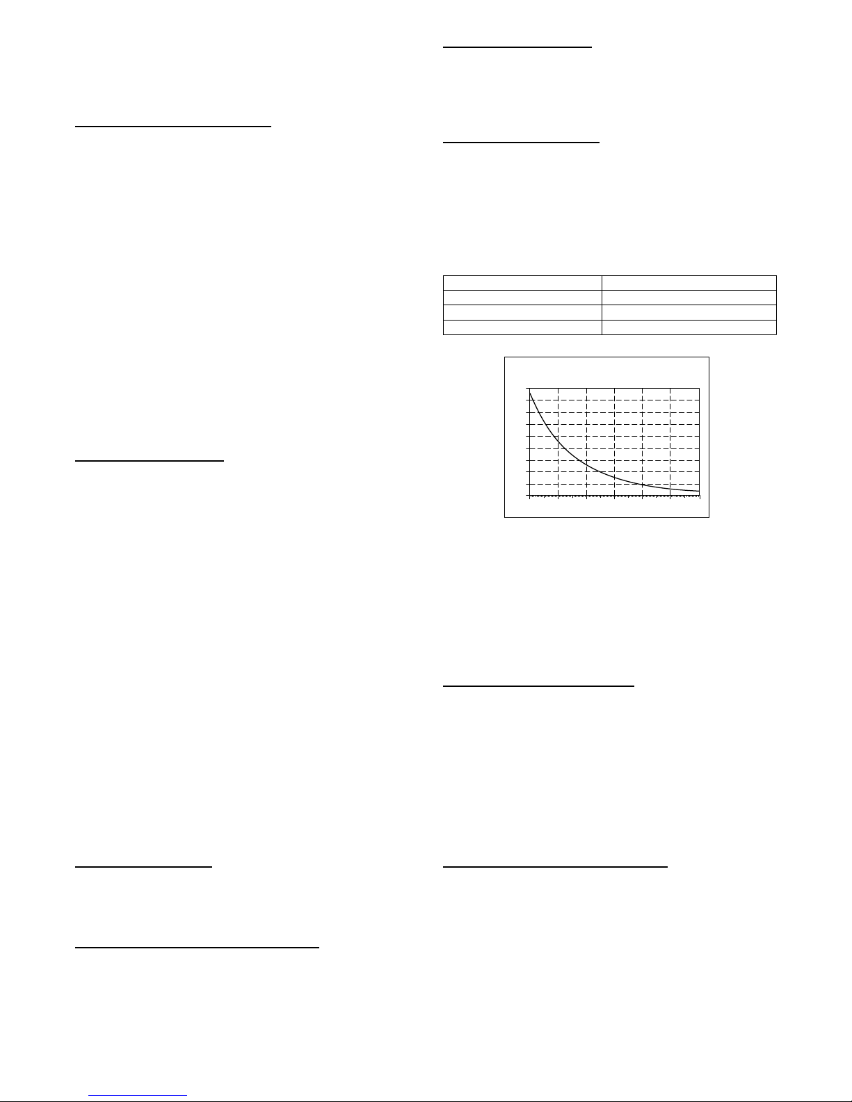
Refer to Table 4 and Fig. 10 for resistance values versus
temperature.
Ta ble 4 – Resistance Values versus Temperature
TEMPERATURE RESISTANCE (ohms)
25.0° C (77.0° F) 10.0 + / - 2.3%
0.0° C (32.0° F) 32.6 + / - 3.2%
-28.0° C (-18.4° F) 85.5 + / - 3.4%
THERMISTOR CURVE
90
80
70
60
50
40
30
20
RESISTANCE (KOHMS)
10
0
0 20 40 60 80 100 120
TEMPERATURE (DEG. F)
A91431
Fig. 10 -- Thermistor Resistance Versus Temperature
If the outdoor air or coil thermistor should fail, the control will
flash the appropriate fault code (see Table 7.)
IMPORTANT: The outdoor air thermistor, coil thermistor and
suction thermistor should be factory mounted in the final
locations. Check to ensure thermistors are mounted properly
(See Fig. 11, 12 and 13).
Thermistor Sensor Comparison
The control continuously monitors and compares the outdoor air
temperature sensor and outdoor coil temperature sensor to ensure
proper operating conditions. The comparison is:
S In cooling if the outdoor air sensor indicates 10_F( 5.6_C)
warmer than the coil sensor (or) the outdoor air sensor indicates
20_F( 11_C) cooler than the coil sensor, the sensors are out
of range.
If the sensors are out of range, the control will flash the appropriate
fault code as shown in Table 7.
The thermistor comparisons are not performed during low ambient
cooling or defrost operation.
Failed Thermistor Default Operation
Factory defaults have been provided in the event of failure of
outdoor air thermistor (OAT) and/or outdoor coil thermistor
(OCT).
If the OAT sensor should fail, low ambient cooling will not be
allowed and the one--minute outdoor fan off delay will not occur.
Defrost will be initiated based on coil temperature and time.
If the OCT sensor should fail, low ambient cooling will not be
allowed.
Count the number of short and long flashes to determine the
appropriate flash code. Table 7 gives possible causes and actions
related to each error.
10
Page 11
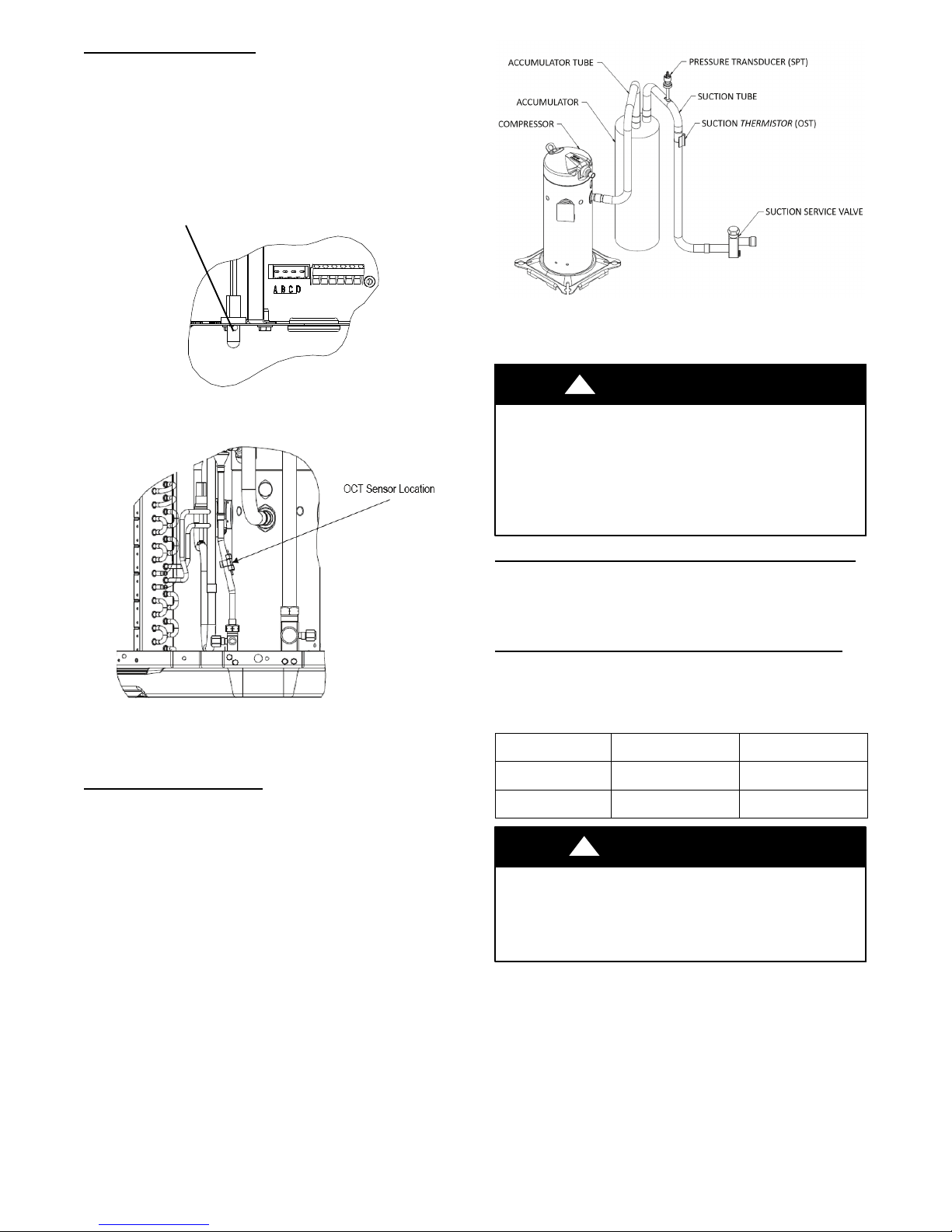
Outdoor Coil Thermistor
The outdoor coil thermistor is a 10Kohm resistor used for multiple
system operations. It provides the coil/liquid line temperature to
the control board and wall control. Low ambient operation and
assistance with OAT temperature measurement of some of the
functions. The sensor must be securely mounted to the tube
connecting OD coil distributor. See Fig. 11 for proper placement.
See Table 4 for proper resistances.
OAT Thermistor must be
locked in place with
spherical n ib end facing
towards the front of the
control box
A170294
Fig. 13 - Suction Thermistor (OST) Attachment
(On Suction Tube)
A11142
Fig. 11 -- OAT Thermistor Location (Bottom of Control Box)
A170293
Fig. 12 -- Outdoor Coil Thermistor (OCT) Attachment
(On Distributor Tube)
Suction Ther mistor (OST)
Suction Thermistor is used for compressor protection and must be
secured on the suction tube and aligned longitudinally to the
vertical surface of the tube axis (see Fig. 13).
!
CAUTION
UNIT DAMAGE HAZARD
Failure to follow this caution may result in equipment
damage or improper operation.
In order to minimize the ambient influence, make sure the
thermistor curved surface hugs the pipe surface and is
secured tight using the wire tie fished through the original
slot insulating polymer body.
Variable Speed Compressor Sensor Output Terminals
This compressor has a motor thermistor and a scroll thermistor.
Correct resistance between scroll thermistor terminal and common
is 10k at 77_F(25_C). Correct resistance between motor
thermistor terminal and common is 5k at 77_F(25_C).
Variable Speed Compressor Power Input Terminals
This compressor operates with a 3--phase variable frequency PWM
variable voltage to the three fusite terminals.
Table 5 – Variable Speed Compressor Resistances
(winding resistance at 70_F 20_F)
WINDING
Between terminals
T1, T2, and T3
Between terminal &
ground
!
180CNV024
180CNV036
.681 .203
>1 mega OHM >1 mega OHM
CAUTION
180CNV048
180CNV060
UNIT DAMAGE HAZARD
Failure to follow this caution may result in equipment damage
and/or improper operation.
Do not use Meggar for measuring the winding resistance.
11
Page 12
ECM Fan Motor
If verification of proper operation is required for the ECM motor
used in this unit, follow these steps:
1. Verify that the 230v input to the transformer is present.
2. Verify that the control board is powered 18 volts to 30 volts
from the transformer.
3. With the UI in charging mode in cooling, measure the DC
voltage between the PWM 1 and PWM 2 terminals on the
outdoor control board. The DC voltage and PWM (optional) measured must be as shown in Table 6.
Table 6 – DC Voltage and PWM Measurement
Unit Size Volt age PWM
24, 36 8.9 VDC 52
48, 60 11.1 VDC 84
Status Codes
Table 7 shows the status codes flashed by the amber status light.
Most system problems can be diagnosed by reading the status code
as flashed by the amber status light on the control board.
The codes are flashed by a series of short and long flashes of the
status light. The short flashes indicate the first digit in the status
code, followed by long flashes indicating the second digit of the
error code.
The short flash is 0.25 seconds ON and the long flash is 1.0 second
ON. Time between flashes is 0.25 seconds. Time between short
flash and first long flash is 1.0 second. Time between code
repeating is 2.5 seconds with LED OFF.
Codes are easily read from wall control.
EXAMPLE:
3 short flashes followed by 2 long flashes indicates a 32 code.
Table 7 shows this to be low pressure switch open.
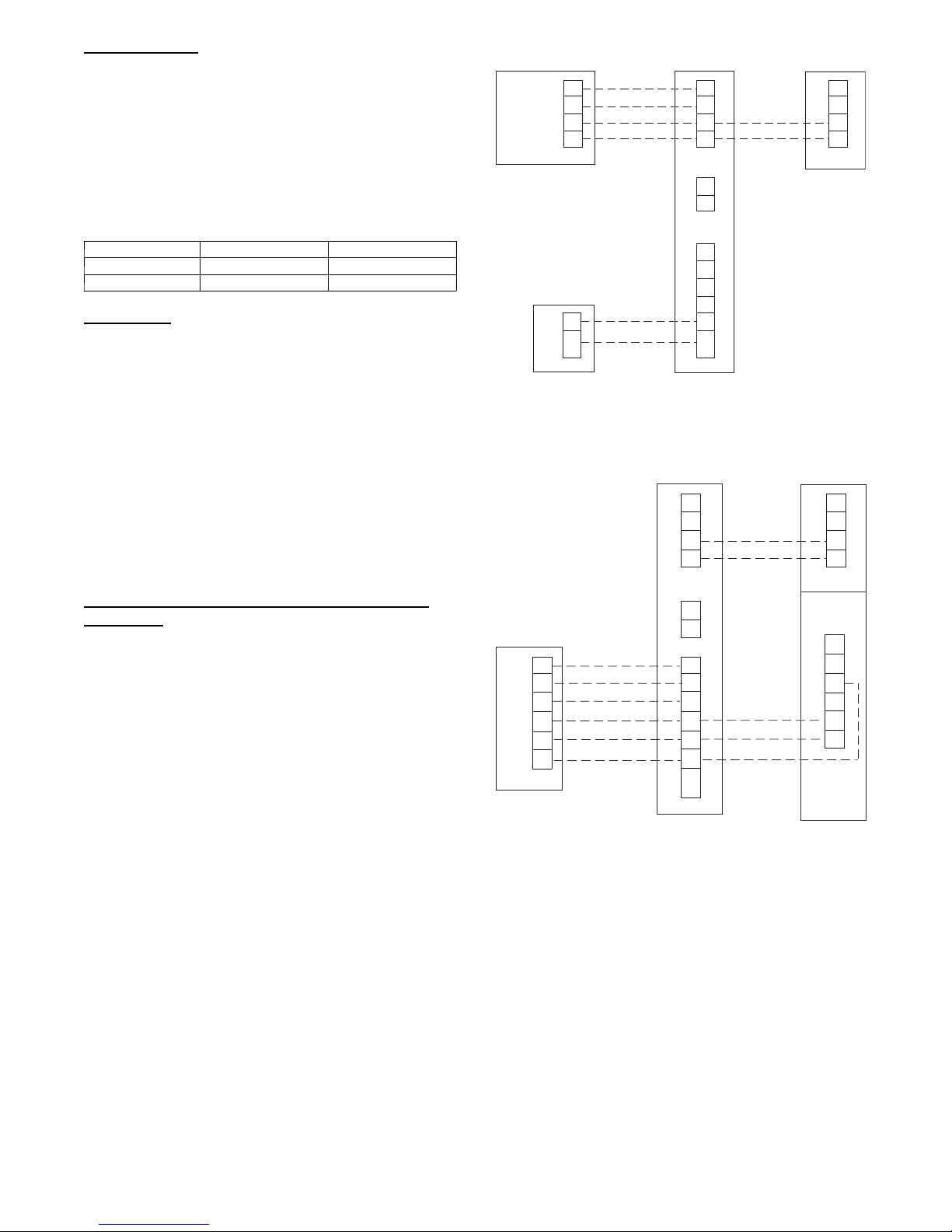
Emergency Mode Connections with a Conventional
Thermostat
In an emergency, it is possible to replace the wall control with a
conventional thermostat. The unit will operate in maximum
cooling speed only.
User Interface (UI)
D
C
B
A
Humidifier
C
24vac
Furnace or Fan Coil
D
C
B
A
OAT
RYOWCHUM
C and D
not required on
VS air conditioner
A12055
VS AC
No
Use
C
B
A
Fig. 14 -- Evolution Furnace or Fan Coil Wiring with Com-
municating Variable Speed AC
Conventional
Dual-Fuel
Thermostat
GYOWC R
Furnace or Fan Coil
A
B
C
D
OAT
R
GYOWCHUM
VS AC
A
B
C
NO
USE
UT
IL
C
LS
Y
O
A11382
Fig. 15 -- Variable Speed Unit Connected to a Conventional
Dual Fuel Thermostat in an Emergency Mode
12
Page 13
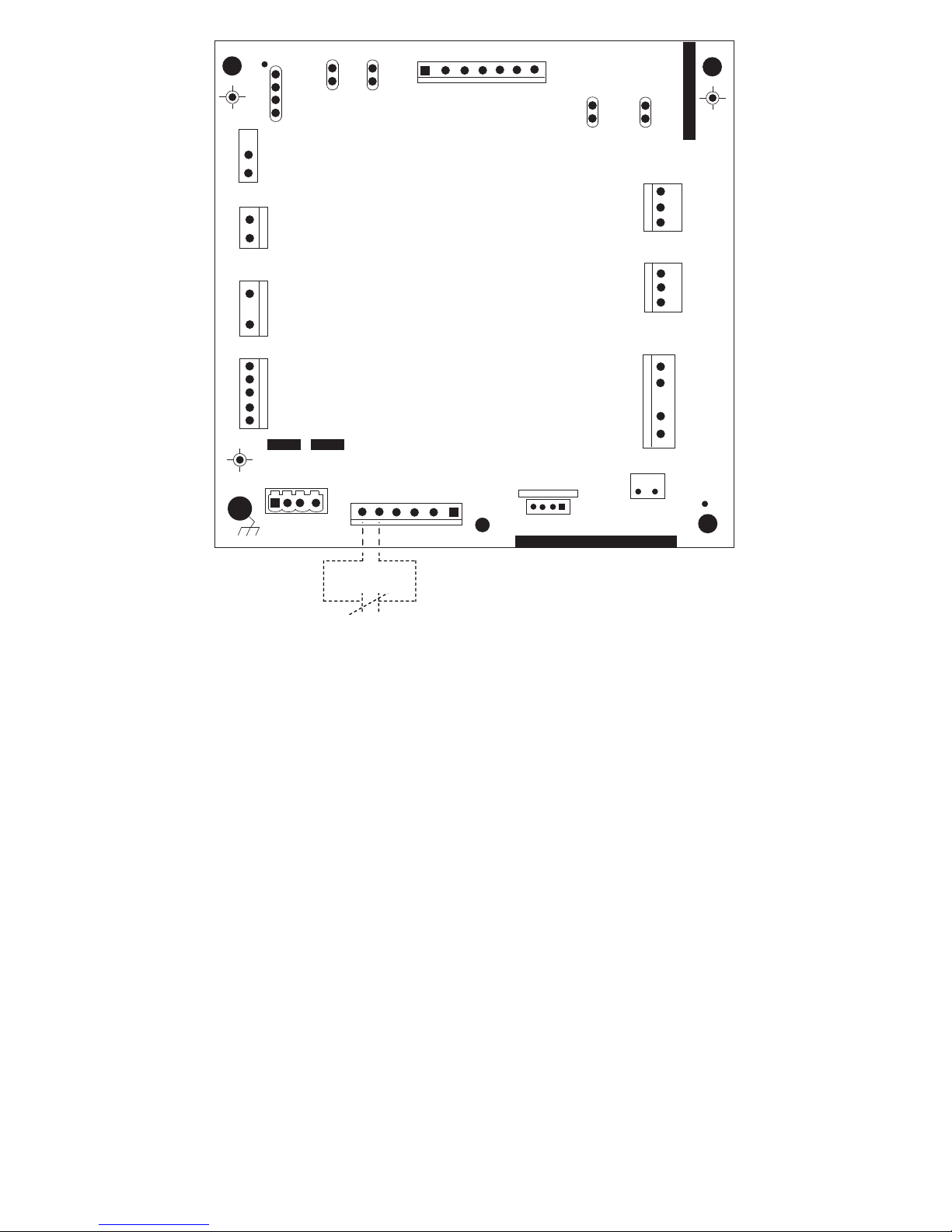
1
RED
SEC1
BRN
SEC2
EXV
PL5
BLU
YEL
PL3
PL2
PL1
CC
HPS
RVS
INVERTER
COMM
B
A
C
NO
USE
STATUS
UTIL
PWM2
PWM1
PL4
SPT
CB
PL11
OST
PL6
OCT
OAT
C
LS
O
Y
PL8
MODEL
J2
FORCED
DEFROST
Utility Interface*
Fig. 16 -- Variable Speed Control Board
with optional Utility Relay
A11544
13
Page 14
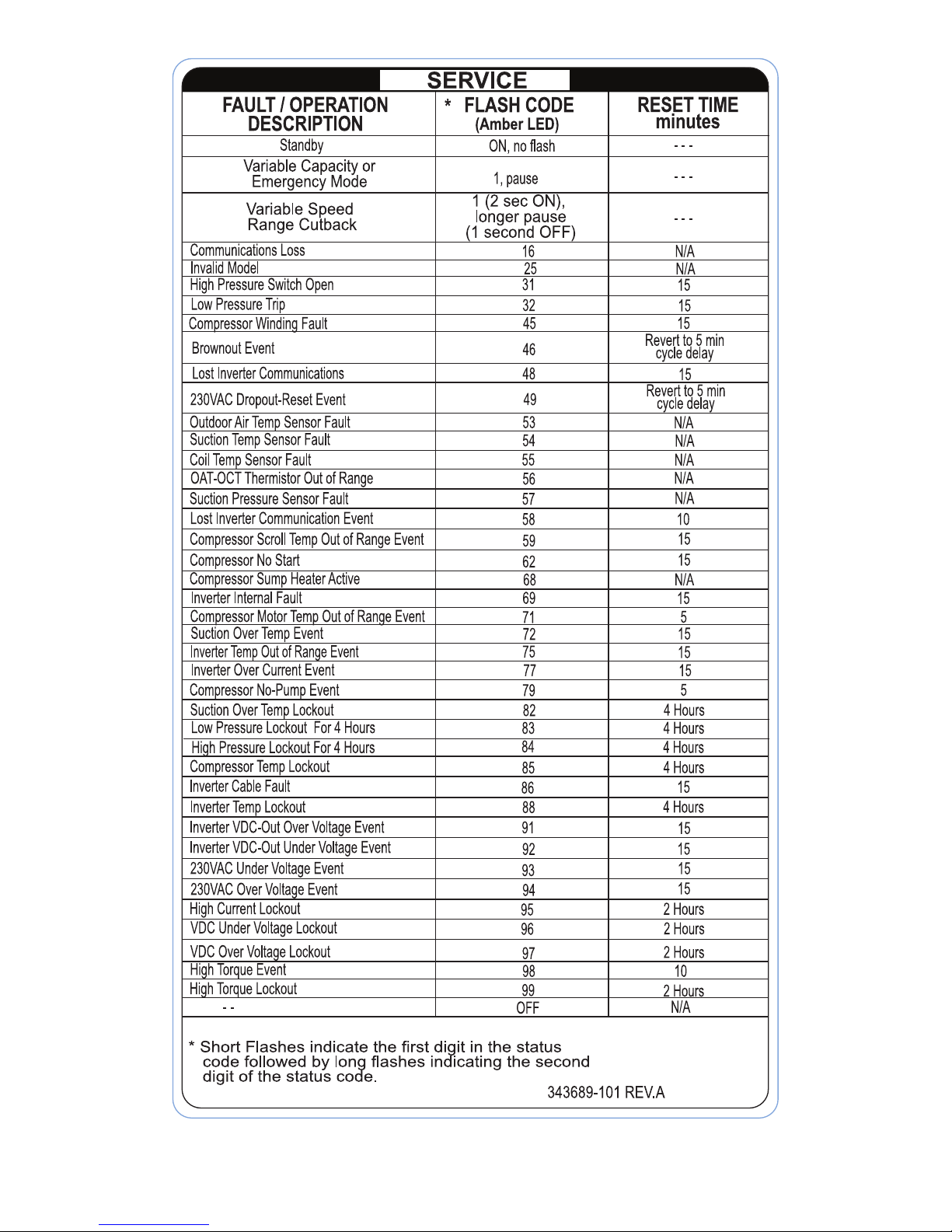
Table 7 – Troubleshooting
14
Page 15

FINAL CHECKS
IMPORTANT: IMPORTANT: Before leaving job, be
sure to do the following:
1. Ensure that all wiring is routed away from tubing
and sheet metal edges to prevent rub--through or
wire pinching.
2. Ensure that all wiring and tubing is secure in unit
before adding panels and covers. Securely fasten
all panels and covers.
3. Tighten service valve stem caps to 1/12-- turn past
finger tight.
4. Leave Users Manual with owner. Explain system
operation and periodic maintenance requirements
outlined in manual.
5. Fill out Dealer Installation Checklist and place in
customer file.
For continuing high performance and to minimize
possible equipment failure, periodic maintenance must be
performed on this equipment.
Frequency of maintenance may vary depending upon
geographic areas, such as coastal applications. See
Owner’s Manual for information.
CARE AND MAINTENANCE
PURONR (R--410A) REFRIGERANT QUICK REFERENCE GUIDE
S Puron refrigerant operates at 50--70 percent higher pressures than R--22. Be sure that servicing equipment and replacement
components are designed to operate with Puron refrigerant.
S Puron refrigerant cylinders are rose colored.
S Recovery cylinder service pressure rating must be 400 psig, DOT 4BA400 or DOT BW400.
S Puron refrigerant systems should be charged with liquid refrigerant. Use a commercial type metering device in the manifold hose
when charging into suction line with compressor operating.
S Manifold sets should be 700 psig high side and 180 psig low side with 550 psig low--side retard.
S Use hoses with 700 psig service pressure rating.
S Leak detectors should be designed to detect HFC refrigerant.
S Puron refrigerant, as with other HFCs, is only compatible with POE oils.
S Vacuum pumps will not remove moisture from oil.
S Do not use liquid--line filter driers with rated working pressures less than 600 psig.
S Do not leave Puron refrigerant suction line filter driers in line longer than 72 hours.
S Do not install a suction--line filter drier in liquid--line.
S POE oils absorb moisture rapidly. Do not expose oil to atmosphere.
S POE oils may cause damage to certain plastics and roofing materials.
S Wrap all filter driers and service valves with wet cloth when brazing.
S A factory-- approved liquid--line filter drier is required on every unit.
S Do NOT use an R --22 TXV.
S If indoor unit is equipped with an R--22 TXV or piston metering device, it must be changed to a hard--shutoff Puron refrigerant
TXV.
S Never open system to atmosphere while it is under a vacuum.
S When system must be opened for service, recover refrigerant, evacuate then break vacuum with dry nitrogen and replace filter
driers. Evacuate to 500 microns prior to recharging.
S Do not vent Puron refrigerant into the atmosphere.
S Do not use capillary tube coils.
S Observe all warnings, cautions,andbold text.
S All indoor coils must be installed with a hard--shutoff Puron refrigerant TXV metering device.
15
Page 16

E2017 Bryant Heating & Cooling Systems 7310 W. Morris St. Indianapolis, IN 46231 Edition Date: 12/17
Manufacturer reserves the right to discontinue, or change at any ti me, specifications or designs without notice and without incurring obligations.
Catalog No. II180CNV--- 0 1
Replaces: New
16
 Loading...