

180B (2 -- 5 Ton)
EVOLUTIONr 20 AIR CONDITIONER
WITH PURONr REFRIGERANT
Product Data
TM
the environmentally sound refrigerant
Bryant’s air conditioners with Puronr refrigerant provide a
collection of features unmatched by any other family of
equipment. The 180B has been designed utilizing Bryant’s
Puronr refrigerant. The environmentally sound refrigerant allows
consumers to make a responsible decision in the protection of the
earth’s ozone layer.
This product has been designed and manufactured to meet
Energy Starr criteria for energy efficiency when matched with
appropriate coil components. Refer to the combination ratings in
the Product Data for system combinations that meet Energy Starr
guidelines.
NOTE: Ratings contained in this document are subject to
change at any time. Always refer to the AHRI directory
(www.ahridirectory.org) for the most up--to--date ratings
information.
INDUSTRY LEADING
FEATURES / BENEFITS
Efficiency
14 -- 20 SEER / 11.6 -- 14.5 EER
S
S Microtube Technologyt refrigeration system
S Indoor air quality accessories available
Sound
Sound level as low as 66 dBA
S
S Electronic ECM ball bearing outdoor condenser fan
motor
S Compressor sound hood
S Forward--swept condenser fan blade
S Quiet mount split post compressor grommets
Comfort
System supports Evolutiont Control or standard
S
2--stage thermostat controls
Reliability
Puronr refrigerant -- environmentally sound, won’t
S
deplete the ozone layer and low lifetime service cost.
S Front--seating service valves
S 2--stage scroll compressor
S Internal pressure relief valve
S Internal thermal overload
S Low pressure switch
S High pressure switch
S Filter drier
S Crank case heater standard
S Balanced refrigeration system for maximum reliability
Durability
DuraGuard Plust protection package:
S Solid, Durable sheet metal construction
S Steel louver coil guard
S Baked--on, complete outer coverage, powder paint
Applications
S Long--line -- up to 250 feet (76.2 m) total equivalent
length, up to 200 feet (60.96 m) condenser above
evaporator, or up to 80 ft. (24.38 m) evaporator above
condenser (See Longline Guide for more information.)
MODEL NUMBER NOMENCLATURE
1234 5 678910111214
NNNAA/NNNNNA/NA/NNA
180B N A036000A
Product
Famil y
1=AC 8=
the environmentally sound refrigerant
180B
Tier SEER Major
0=21
Evolution
Series
SEER
Nominal
Use of the AHRI Certified
TM Mark indicates a
manufacturer’s
participation in the
program For verification
of certification for individual
products, go to
www.ahridirectory.org.
Series
Voltage Variation s Coolin g Capacity Open Open Open Minor
B=Puron N=
208--- 230--- 1
A=
Standard
0=Not
Defined0=Not
Defined
This product has been designed and manuf actured t o
meet En ergy St ar® criteria for energy efficiency when
matched with appropriate coil components. However,
proper refrigerant charge and proper air flow are critical
to achieve rated capacity and efficiency. Installation of
this product should f ollow all manufacturing refrigerant
charging and air flow instructions. Failure to confirm
proper charge an d air flow may reduce energy
efficiency and shorten equ ipment life.
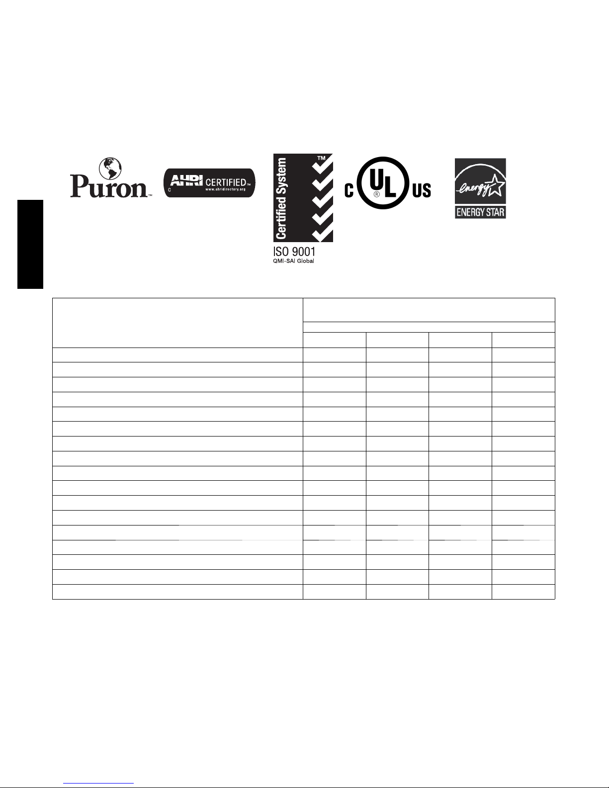
STANDARD FEATURES
MODEL
FEATURES
024---A 036--- B 048- -- A 060--- A
Puron Refrigerant X X X X
Maximum SEER Rating 21.0 20.0 17.7 16.7
2 --- Stage Scroll Compressor X X X X
Crankcase Heater w/Temperature Switch X X X X
Long line Capability X X X X
Low Ambient Capability to 0_F ( --- 1 7 .8_C) w/Evolution Control X X X X
Advanced Diagnostics with Evolution Control X X X X
Utility Interface Conn ection X X X X
Louvered Coil Guard X X X X
FieldInstalledFilterDrier X X X X
Fron t Seating Serv ice Valv es X X X X
Internal Pressure Relief Valve X X X X
Internal Thermal Overload X X X X
Long Line capability X X X X
Low Pressure Switch X X X X
High Pressure Switch X X X X
Sound Blanket X X X X
* With approved combinations
X=Standard
UNIT SIZE---SERIES
180BNA
0=
Not
Defined
Series
A=
Original
Series
2
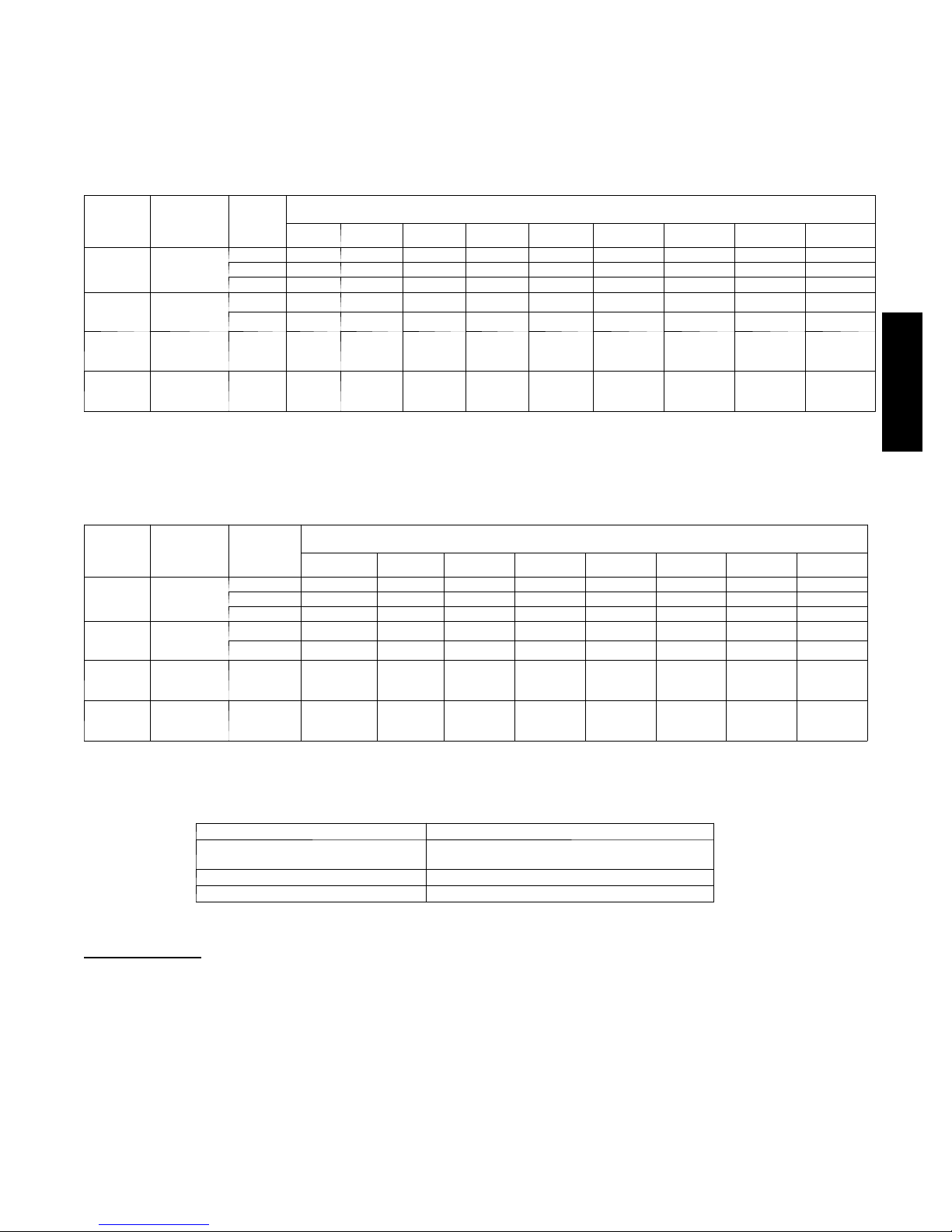
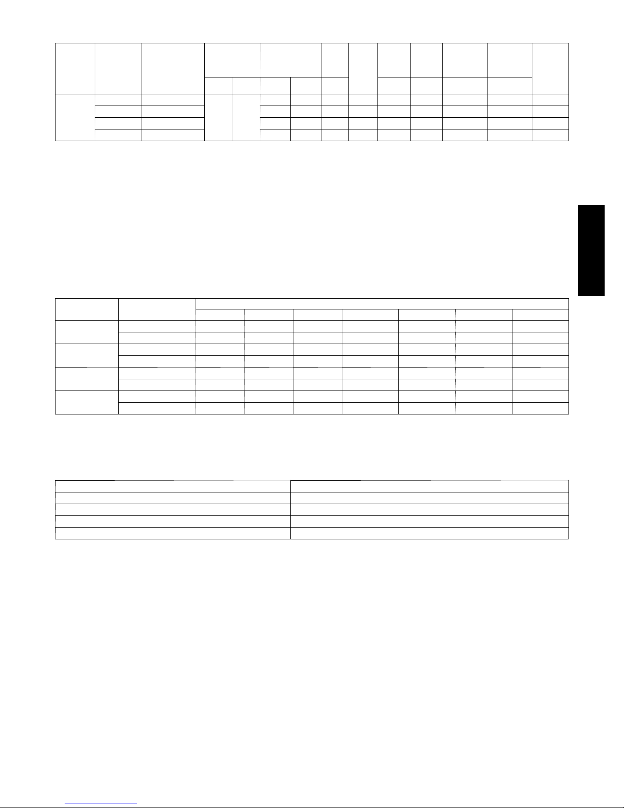
REFRIGERANT PIPING LENGTH LIMITATIONS
Liquid Line Sizing and Maximum Total Equivalent Lengths
The maximum allowable length of a residential split system depends on the liquid line diameter and vertical separation between indoor and
outdoor units.
See Table below for liquid line sizing and maximum lengths :
Maximum Total Equivalent Length
Outdoor Unit BELOW Indoor Unit
Liquid
Size
024
AC with
Puron
036
AC with
Puron
048
AC with
Puron
060
AC with
Puron
* Maximum actual length not to exceed 200 ft (61 m)
{ Total equivalent length accounts for losses due to elbows or fitting. See the Long Line Guideline for details.
--- --- = o u t s i d e a c c e p t ab l e r an g e
Size
024
AC with
Puron
036
AC with
Puron
048
AC with
Puron
060
AC with
Puron
* Maximum actual length not to exceed 200 ft (61 m)
{ Total equivalent length accounts for losses due to elbows or fitting. See the Long Line Guideline for details.
Liquid Line
Connection
3/8
3/8
3/8 3/8 250* 250* 250* 250* 250* 250* 230 160 --- ---
3/8 3/8 250* 250* 250* 225* 190 150 110 --- --- --- ---
Liquid Line
Connection
3/8
3/8
3/8 3/8 250* 250* 250* 250* 250* 250* 250* 250*
3/8 3/8 250* 250* 250* 250* 250* 250* 250* 250*
Line
Diam.
w/TXV
1/4 75 75 75 50 50 --- --- --- --- --- --- --- ---
5/16 250* 250* 250* 250* 250* 225* 175 125 100
3/8 250* 250* 250* 250* 250* 250* 250* 250* 250*
5/16 175 150 150 100 100 100 75 --- --- --- ---
3/8 250* 250* 250* 250* 250* 250* 250* 250* 250*
Liquid
Diam.
w/TXV
(0--- 1.5)
Line
1/4 100 125 175 200 225* 250* 250* 250*
5/16 250* 250* 250* 250* 250* 250* 250* 250*
3/8 250* 250* 250* 250* 250* 250* 250* 250*
5/16 225* 250* 250* 250* 250* 250* 250* 250*
3/8 250* 250* 250* 250* 250* 250* 250* 250*
AC with Puron Refrigerant Maximum Total Equivalent Length{: Outdoor unit BELOW Indoor
0 --- 5
6 --- 1 0
(1.8--- 3.0)
11--- 20
(3.4--- 6.1)
Maximum Total Equivalent Length
Outdoor Unit ABOVE IndoorUnit
AC with Puron Refrigerant Maximum Total Equivalent Length{: Outdoor unit ABOVE Indoor
25
(7.6)
26--- 50
(7.9--- 15.2)
{
for Cooling Only Systems with Puronr Refrigerant:
Vertical Separation ft (m)
21--- 30
(6.4--- 9.1)
51--- 75
(15.5--- 22.9)
31--- 40
(9.4--- 12.2)
Vertical Separation ft (m)
76--- 100
(23.2--- 30.5)
41--- 50
(12.5--- 15.2)
101--- 125
(30.8--- 38.1)
51--- 60
(15.5--- 18.3)
126--- 150
(38.4--- 45.7)
61--- 70
(18.6--- 21.3)
151--- 175
(46.0--- 53.3)
71--- 80
(21.6--- 24.4)
176--- 200
(53.6--- 61.0)
180B
Liquid Line Size Puron Charge oz/ft (g/m)
3/8
5/16 0.40 (11.83)
1/4 0.27 (7.98)
Units are factory charged for 15 ft (4.6 m) of 3/8” liquid line. The factory charge for 3/8” lineset 9 oz.(266.16 g). When using other length
or diameter liquid lines, charge adjustments are required per the chart above.
Charging
Formula:
[(Lineset oz/ft x total length) – (factory charge for lineset)] = charge adjustment
Example 1: System has 15 ft of line set using existing 1/4“ liquid line. What charge adjustment is required?
Formula: (.27 oz/ft x 15ft) – (9 oz) = (-4.95) oz.
Net result is to remove 4.95 oz of refrigerant from the system
Example 2: System has 45 ft of existing 5/16” liquid line. What is the charge adjustment?
Formula: (.40 oz/ft. x 45ft) – (9 oz.) = 9 oz.
Net result is to add 9 oz of refrigerant to the system
REFRIGERANT CHARGE ADJUSTMENTS
0.60 (17.74)
(Factory charge for lineset = 9 oz / 266.16 g)
3
LONG LINE APPLICATIONS
An application is considered Long Line, when the refrigerant level in the system requires the use of accessories to maintain acceptable
refrigerant management for systems reliability. See Accessory Usage Guideline table for required accessories. Defining a system as long line
depends on the liquid line diameter, actual length of the tubing, and vertical separation between the indoor and outdoor units.
For Air Conditioner systems, the chart below shows when an application is considered Long Line.
AC WITH PURONr REFRIGERANT LONG LINE DESCRIPTION ft (m)
Beyond these lengths, long line accessories are required
Liquid Line Size Units On Same Level Outdoor Below Indoor Outdoor Above Indoor
1/4
5/16 120 (36.6) 50 (15.2) vertical or 120 (36.6) total 120 (36.6)
3/8 80 (24.4) 35 (10.7) vertical or 80 24.4) total 80 (24.4)
Note: SeeLongLineGuidelinefordetails
No accessories needed within allowed
lengths
No accessories needed within allowed
lengths
175 (53.3)
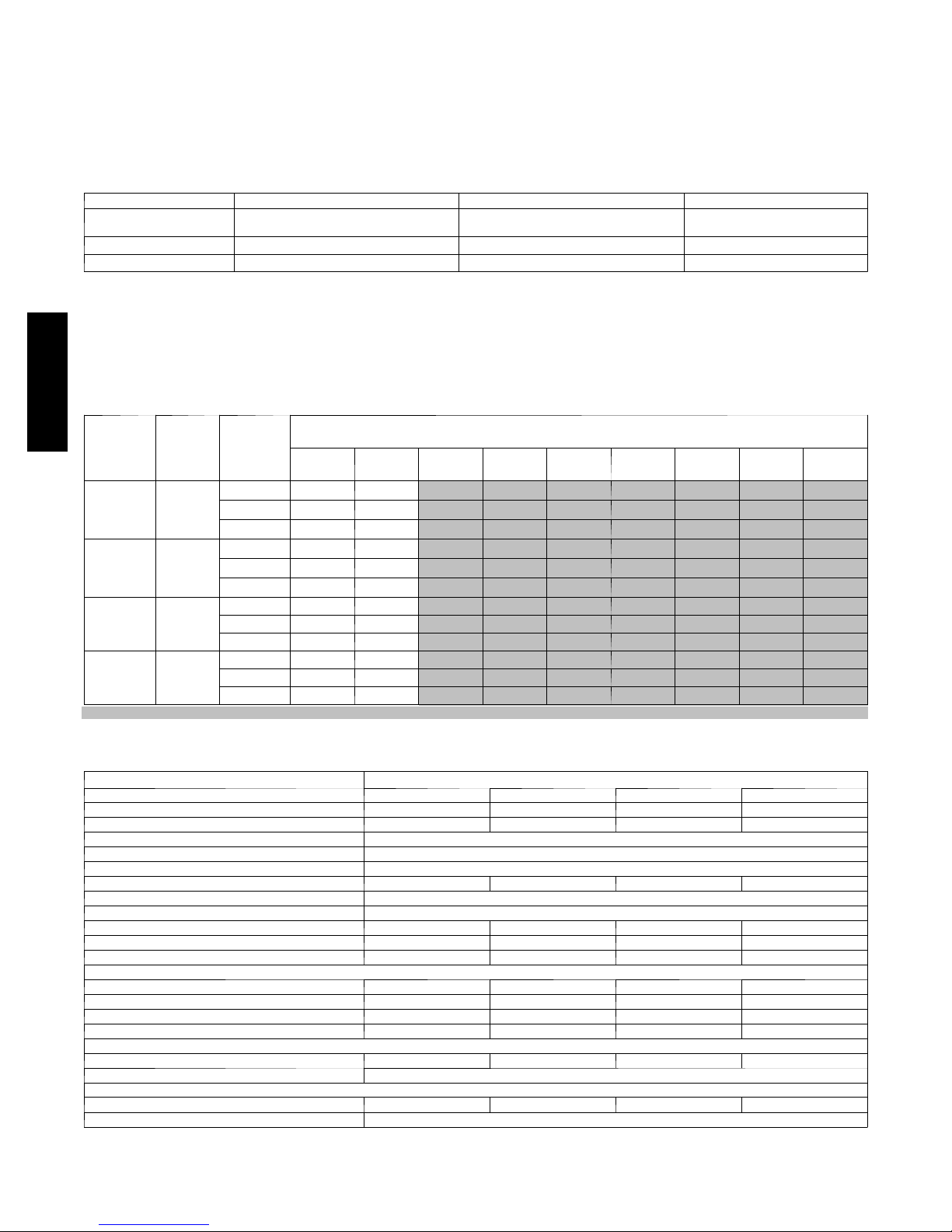
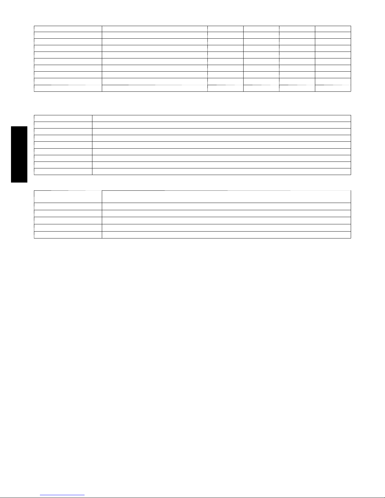
VAPOR LINE SIZING AND COOLING CAPACITY LOSS
Acceptable vapor line diameters provide adequate oil return to the compressor while avoiding excessive capacity loss. The suction line
diameters shown in the chart below are acceptable for AC systems with Puron refrigerant:
180B
Nominal
Size (Btuh)
2 --- St a g e
Puron
2 --- St a g e
Puron
2 --- St a g e
Puron
2 --- St a g e
Puron
Applications in this area may be long line and may have height restrictions. See the Residential Piping and Long Line Guideline.
— Applications in this area are not recommended due to insufficient oil return
Vapor Line Sizing and Cooling Capacity Losses — Puronr Refrigerant 2--Stage Air Conditioner Applications
Unit
024
AC
036
AC
048
AC
060
AC
Maximum
Liquid
Line
Diameters
(In. OD)
3/8
3/8
3/8
3/8
Vapo r Line
Diameters
(In.) OD
5/8 0 1 1 2 3 3 4 4 5
3/4 0 0 0 0 1 1 1 1 1
7/8 0 0 0 0 1 1 1 1 1
5/8 1 2 4 5 6 7 9 10 11
3/4 0 0 1 1 2 2 3 3 4
7/8 0 0 0 0 1 1 1 1 2
3/4 1 2 2 3 4 5 6 7 7
7/8 0 1 1 2 2 2 3 3 3
1 --- 1/8 0 0 — — — — — — —
3/4 1 2 4 5 6 7 9 10 11
7/8 0 1 2 2 3 4 4 5 5
1 --- 1/8 0 0 0 1 1 1 1 1 1
26---50
(7.9--- 15.2)
51---80
(15.5--- 24.4)
81---100
(24.7--- 30.5)
Cooling Capacity Loss (%)
Total Equivalent Line Length ft. (m)
101---125
(30.8--- 38.1)
126---150
(38.4--- 45.7)
151---175
(46.0--- 50.3)
176---200
(53.6--- 60.0)
201---225
(61.3--- 68.6)
PHYSICAL DATA
Model 180BNA
Unit Size -- - Series 024---A 036--- B 048---A 060--- A
Operating Weight lb (kg) 323 (147) 324 (147) 325 ( 147) 350 (159)
Shipping Weight lb (kg) 368 (167) 368 (167) 370 ( 168) 394 (179)
Compressor Ty pe 2 --- Stage S c r o l l
REFRIGERANT Puronr (R --- 410A)
Control TXV (Puronr Hard Shutoff)
Charge lb (kg) 14.21 (6.67) 14.36 (6.51) 14.45 (6.55) 14.83 (6.73)
COND FAN Propeller Type, Direct Drive
Air Discharge Vertical
Air Qty (CFM) 3000 / 3637 3124 / 3700 3703 / 4304 4209 / 4668
Motor HP 1/5 1/5 1/5 1/5
Motor RPM 628 / 752 582 / 669 659 / 765 742 / 828
COND COIL
Face Area (Sq ft) 30.18 30.18 30.18 30.18
Fins per In. 20 20 20 20
Rows 2 2 2 2
Circuits 9 9 9 9
VALVECONNECT.(In.ID)
Vapor 7/8 7/8 7/8 7/ 8
Liquid 3/8
REFRIGERANT TUBES (In. OD)
Rated Vapor* 7/8 7/8 1 --- 1/8 1 --- 1/8
Liquid 3/8
*Units are rated with 25 ft (7.6 m) of lineset length. See Vapor Line Sizing and Cooling Capacity Loss table when using other sizes and lengths of lineset.
226---250
(68.9--- 76.2)
4
ELECTRICAL DATA
UNIT
MODEL
180BNA
* Permissible limits of the voltage range at which the unit will operate satisfactorily
{ If wire is applied at ambient greater than 30_C, consult table 310 --- 16 of the NEC (NFPA 70) . The ampacity of non---metallic--- sheathed cable (NM), trade
name ROMEX, shall be that of 60_C conditions, per the NEC (NFPA 70) Article 336--- 26. If other th a n u ncoated ( no---plated), 60 or 75_C insulation, copper
wire (solid wire for 10 AWG or smaller, stranded wire for larger than 10 AWG) is u sed, consult applicable tables of the NEC (NFPA 70).
} Length shown is as measured one way along wire path between unit and service panel for voltage drop not to exceed 2%.
* * T i m e --- D e l a y f u s e .
FLA --- Ful l L o a d A m ps
LRA --- L o c k e d R o t or A mps
MCA --- Minimum Circuit Amps
RLA ---RatedLoadAmps
NOTE: Control circuit is 24---V on all units and requires external power source. Copper wire must be used from service disconnect to unit.
Complies with 2010 requirements of ASHRAE Standards 90.1
S I Z E ---
SERIES
024---A 208/230---1---60
036---B 208/230--- 1--- 60 82.0 16.70 1.7 22.6 12.00 12.00 65 (16.8) 53 (16.2) 35
048---A 208/230---1---60 96.0 21.20 1.9 28.4 10.00 10.00 70 (21.3) 67 (20.4) 40
060---A 208/230---1---60 118.0 23.00 1.9 30.7 8.00 10.00 101 (30.8) 62 (18.9) 50
All motors/compressors contain internal overload protection.
V --- P H --- H z
OPER
VOLTS*
MAX MIN LRA RLA FLA 60°C 75°C 60°C 75°C
253 197
COMPR FA N
MCA
52.0 10.30 1.4 14.3 14.00 14.00 55 (16.8) 52 (15.9) 20
MIN
WIRE
SIZE{
MIN
WIRE
SIZE{
MAX
LENGTH
ft (m)}
MAX
LENGTH
ft (m)}
MAX
FUSE*
*or
CKT
BRK
AMPS
A--WEIGHTED SOUND POWER (dBA)
UNIT SIZE
180BNA024 ---A
180BNA036 ---B
180BNA048 ---A
180BNA060 ---A
NOTE: Tested in accordance with AHRI Standard 270---08. (Not listed with AHRI).
STANDARD
RATING (dBA)
* 6 9 --- l ow s t a g e 46.5 52.5 59.0 65.0 54.5 53.0 47.5
7 1 --- hig h s t a g e 48.5 54.5 63.0 59.5 58.0 58.5 54.5
* 6 9 --- l ow s t a g e 49.0 53.5 61.5 63.0 56.5 53.5 49.5
7 2 --- hig h s t a g e 49.5 55.5 67.0 63.5 57.5 53.0 56.0
* 6 6 --- l ow s t a g e 47.5 56.0 61.5 59.0 56.0 52.5 50.0
7 1 --- hig h s t a g e 48.5 59.0 66.0 64.5 58.5 57.0 54.5
* 6 9 --- l ow s t a g e 50.5 59.0 63.0 62.5 58.5 58.0 55.0
7 2 --- hig h s t a g e 53.5 60.5 65.0 67.0 60.0 58.5 54.5
125 250 500 1000 2000 4000 8000
TYPICAL OCTAVE BAND SPECTRUM (dBA, without tone adjustment)
180B
CHARGING SUBCOOLING (TXV--TYPE EXPANSION DEVICE)
UNIT SIZE --- SERIES
180BNA024 ---A
180BNA036 ---B
180BNA048 ---A
180BNA060 ---A
REQUIRED SUBCOOLING _F(_C)
9 (5.0) HIGH STAGE
12 (6.7) HIGH STAGE
14 (7.8) HIGH STAGE
16 (8.9) HIGH STAGE
5
ACCESSORIES
KIT NUMBER KIT NAME 024---A 036 --- B 048---A 060- -- A
KSAHS2301AAA HARD START KIT X
KSAHS2401AAA HARD START KIT X
KSAHS2501AAA HARD START KIT X
KSAHS2601AAA HARD START KIT X
KSASF0101AAA SUPPORT FEET X X X X
KSATX0201PUR TXV X
KSATX0301PUR TXV X
KSATX0401PUR TXV X
KSATX0501PUR TXV X
x = Accessory
CONTROLS
CONTROL DESCRIPTION
SYSTXBBUID01 --- D Evolution Control Deluxe 7 ---Day Programmable (Wall --- mounted system control.)
SYSTXBBUIZ01 ---D Evolution Control Deluxe Zoning 7 ---Day Programmable (Wall--- mounted control for a multi--- zone system.)
SYSTXBB4ZC01 Evolution 4--- Zone Damper Control Module (Wall---mounted control for a four---zone system.)
SYSTXBBSMS01 Evolution Smart Sensor (Optional wall control used to monitor temperature and/or fan control in an individual zone.)
SYSTXBBRRS01 E volution Remote Room Sensor (Monitors temperature in an individual zone.)
SYSTXBBRWF01 Evolution System Access Module (Hardware for wireless access an d control via phone or internet.)
180B
SYSTXBBNIM01 Evolution Network Interface Module (Connects Heat Recovery and Energy Recovery Ventilators on non--- zoning applications.)
SYSTXBBLBPU01 --- C Decorative Back Plate for Evolution Control (Decorative wall plate.)
THERMOSTATS
THERMOSTAT / SUBBASE
PKG.
T 6 --- P R H 01 --- A Programmable Thermidistat
T 6 --- N R H 01 --- A Non --- programmable Thermidistat
T 6 --- PA C 0 1 Preferred Series Programmable AC Stat
T 6 --- N A C 01 Preferred Series Non---programmable AC Stat
TSTATXXSEN01--- B Outdoor Air Temperature Sensor
DESCRIPTION
6
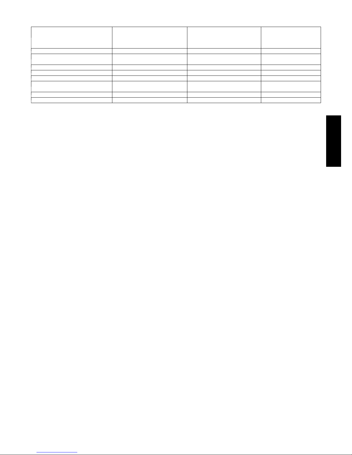
ACCESSORY USAGE GUIDELINE
REQUIRED FOR
ACCESSORY
Compressor Start Assist Kit No Ye s No
Crankcase Heater
Evaporator Freeze Protection Standard with Evolution Control No No
Liquid--- Line Solenoid Valve No No No
Low--- Ambient Control Standard with Evolution Control No No
Puron Refrigerant Balance Port Hard---
* For tubing set lengths between 80 and 200 ft. (24.38 and 60.96 m) horizontal or 35 ft. (10.7 m) vertical differential (total equivalent len gth), refer to the Long
Line Guideline—Air Conditioners and Heat Pumps using Puron® Refrigerant.
{ Required on all indoor units. Standard on all new Puron refrigerant fan coils and furnace coils.
ShutOff TXV
Support Feet Recommended No Recommended
Winter Start Control Standard with Evolution Control No No
L O W --- A M B I E N T C O O L I N G
APPLICATIONS
(Below 55°F/12.8_C)
Ye s
(standard on some units)
Ye s{
REQUIRED FOR LONG LINE
APPLICATIONS*
Ye s
(standard on some units)
Ye s{
REQUIRED FOR SEA COAST
APPLICATIONS
(Within 2 miles/3.22 km)
No
Ye s{
Accessory Description and Usage (Listed Alphabetically)
1. Compressor Start Assist -- Capacitor and Relay
Start capacitor and relay gives a ”hard” boost to compressor
motor at each start up.
Usage Guideline:
Required for reciprocating compressors in the
following applications:
Long line
Hard shut off expansion valve on indoor coil
Liquid line solenoid on indoor coil
Required for single--phase scroll compressors in the
following applications:
Long line
Suggested for all compressors in areas with a history of
low voltage problems.
2. Crankcase Heater
An electric resistance heater which mounts to the base of the
compressor to keep the lubricant warm during off cycles.
Improves compressor lubrication on restart and minimizes the
chance of liquid slugging.
Usage Guideline:
Required in low ambient cooling applications.
Required in long line applications.
Suggested in all commercial applications.
3. Outdoor Air Temperature Sensor
Designed for use with Bryant Thermostats listed in this
publication. This device enables the thermostat to display the
outdoor temperature. This device also
is required to enable special thermostat features such as auxiliary
heat lock out.
Usage Guideline:
Suggested for all Bryant thermostats listed in this
publication.
4. Support Feet
Four stick--on plastic feet that raise the unit 4 in. (101.6 mm)
above the mounting pad. This allows sand, dirt, and other debris
to be flushed from the unit base, minimizing corrosion.
Usage Guideline:
Suggested in the following applications:
Coastal installations.
Windy areas or where debris is normally circulating.
Rooftop installations.
For improved sound ratings.
5. Thermostatic Expansion Valve (TXV)
A modulating flow--control valve which meters refrigerant liquid
flow rate into the evaporator in response to the superheat of the
refrigerant gas leaving the evaporator.
Kit includes valve, adapter tubes, and external equalizer tube.
Hard shut off types are available.
NOTE: When using a hard shut off TXV with single phase
reciprocating compressors, a Compressor Start Assist Capacitor
and Relay is required.
Usage Guideline:
Required to achieve AHRI ratings in certain equipment
combinations. Refer to combination ratings.
Hard shut off TXV or LLS required in air conditioner
long line applications.
Required for use on all zoning systems.
180B
7
 Loading...