


Project
:
Brusa ICS
Product description
:
Wireless Power Transfer System (WPT
-
System)
Manufacturer
:
Zollner Elektronik AG
Applicant
:
Brusa
Date of issue
: 21.12.2017
Document number
:
User_Manual_Wlan_Module_Brusa.docx
Stages of
Prototype
: D-
Sample
PMN
: W-
LAN Card
HVIN
:
ICS1
-
WLAN
-
ATWILC
-MU-D
BRUSA Elektronik AG
Neudorf 14,
CH–9466 Sennwald
The user of this document is liable to keep track on changes!
User Manual Wlan Module
Project number : P0006 – 10281E
address : Manfred-Zollner-Str. 1
93499 Zandt
Germany
address : Neudorf 14
9466 Sennwald
Schweiz
Created by:
Kai Lanzl, 12.03.2018
Name, Date
User_Manual_Wlan_Module_Brusa_V1.4_final.docx
Page 1 of 35

BRUSA Elektronik AG
Neudorf 14,
CH–9466 Sennwald
Contents
1 Change Index ............................................................................................ 3
2 Acronyms and Abbreviations .................................................................. 3
3 Introduction ............................................................................................... 4
3.1 Product Description ................................................................................................. 4
3.2 Theory of Operation ................................................................................................. 4
3.3 System Description .................................................................................................. 4
3.4 Block Diagram ......................................................................................................... 5
3.5 Module Drawings ..................................................................................................... 5
3.6 Module Pin Description ............................................................................................ 6
3.7 Photo Documentation .............................................................................................. 7
3.8 Dimensions .............................................................................................................. 8
3.9 DuT Configuration and Test Setup .......................................................................... 8
4 Requirements ............................................................................................ 9
4.1 Power Supply System utilized.................................................................................. 9
4.2 Modulations ............................................................................................................. 9
4.3 Operation Frequency and Channel Plan .................................................................. 9
5 User Manual ............................................................................................. 10
5.1 Test Software......................................................................................................... 10
5.2 Module Configuration ............................................................................................. 12
5.3 Aardvark Adapter ................................................................................................... 12
5.4 Adapter Board........................................................................................................ 13
5.5 Initial Startup .......................................................................................................... 15
5.6 Transmitting and Receiving ................................................................................... 16
5.7 Adaptivity Testing .................................................................................................. 22
6 General Remarks .................................................................................... 28
7 Attachment .............................................................................................. 29
8 List of Figures ......................................................................................... 35
9 List of Tables ........................................................................................... 35
User_Manual_Wlan_Module_Brusa_V1.4_final.docx
Page 2 of 35

BRUSA Elektronik AG
Neudorf 14,
CH–9466 Sennwald
1 Change Index
Version Author / Department Comment Date
1.0 Kai Lanzl, DRQ Initial version, current version 24.03.2017
1.1 M. Binder, DRQ FCC statement added 21.12.2017
Table 1: Change index
2 Acronyms and Abbreviations
Appellation Description
CPM Car pad module
DuT Device under test
FOD Foreign object detection
GPM Ground pad module
HW Hardware
ICS Inductive charging system
LOD Living object detection
SW Software
WPT Wireless power transfer
Table 2: List of abbreviations
User_Manual_Wlan_Module_Brusa_V1.4_final.docx
Page 3 of 35

BRUSA Elektronik AG
Neudorf 14,
CH–9466 Sennwald
3 Introduction
This document serves as a user manual for the Brusa Wlan module.
3.1 Product Description
The WLAN module is based on the Atmel ATWINC1000B_MUT chip. The special feature of
this module is that it is capable of being exposed to operating temperatures up to 125°C. The
module was developed by Brusa and Wepotec.
3.2 Theory of Operation
The WLAN module establishes the connection between CPM and GPM. The GPM module
sends continuous beacons and if a CPM is in the radio range they start communicating.
The ICS is separated into several parts (Energy transmission, positioning system, FOD /
LOD) and each part uses WLAN to change information between CPM and GPM e.g. the
charging process begins after the CPM has sent the charging command via WLAN to the
GPM.
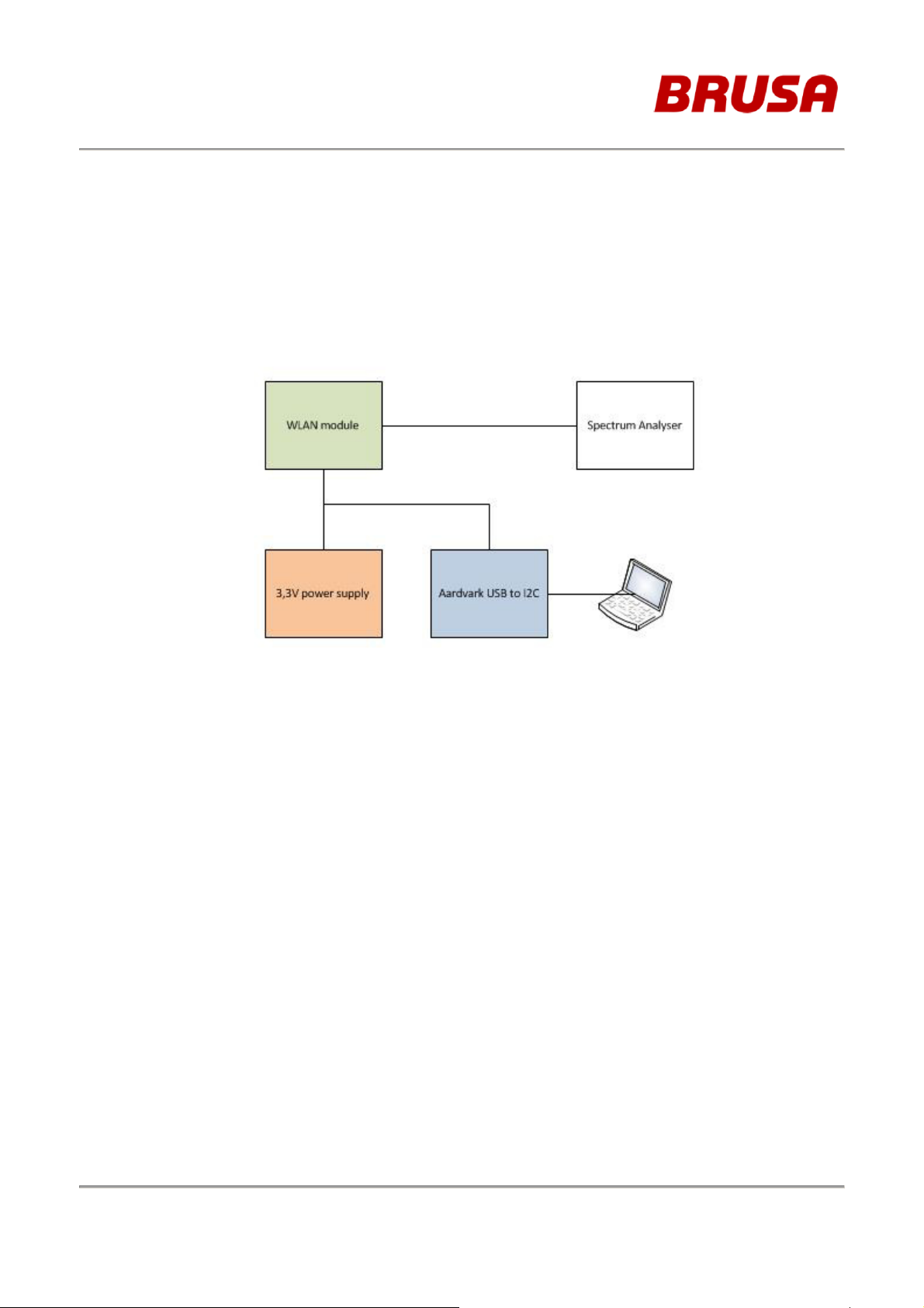
3.3 System Description
Figure 1: System description
User_Manual_Wlan_Module_Brusa_V1.4_final.docx
Page 4 of 35

BRUSA Elektronik AG
Neudorf 14,
CH–9466 Sennwald
3.4 Block Diagram
VBAT/VDDIO
RX/TX
Figure 2: Block diagram ATWINC1000B_MUT
3.5 Module Drawings
GND
I2C
SPI/SDIO
IRQN
Chip_EN
Wake
Reset
Figure 3: Wlan module top view
User_Manual_Wlan_Module_Brusa_V1.4_final.docx
Page 5 of 35

BRUSA Elektronik AG
Neudorf 14,
CH–9466 Sennwald
3.6 Module Pin Description
The pins are shown in Figure 3 on the right side of the module:
Pin Description
1 VBATT
2 GND
3 I2C_SDA
4 I2C_SCL
5 Resetn
6 Chip_EN
7 GND
8 UART_RXD (SD_CLK)
9 SCK (SD_CMD)
10 TXD (SD_DAT0)
11 SSN_(SD_DAT1)
12 RXD (SD_DAT2)
13 UART_RXD (SD_DAT3)
14 IRQN (GPIO2)
15 HOST_WAKE (GPIO0)
Table 3: Module pin description
Note: Only pins with grey background are necessary for EMC tests!
User_Manual_Wlan_Module_Brusa_V1.4_final.docx
Page 6 of 35

BRUSA Elektronik AG
Neudorf 14,
CH–9466 Sennwald
3.7 Photo Documentation
Figure 4: Wlan modules top view
Figure 5: Wlan modules bottom view
User_Manual_Wlan_Module_Brusa_V1.4_final.docx
Page 7 of 35
BRUSA Elektronik AG
Neudorf 14,
CH–9466 Sennwald
3.8 Dimensions
Width (mm) ►
60
Depth (mm)
►
3.9 DuT Configuration and Test Setup
1
Hight (mm)
►
60
Figure 6: DuT test setup
The following peripheral devices and interface cables will be connected during the
measurements:
- Power supply Model: n.a.
- I2C adapter Model: Aardvark.
- Laptop Model: n.a.
- Spectrum Analyser Model: n.a.
- WLAN module Model: n.a.
- Adapter board Model: n.a.
User_Manual_Wlan_Module_Brusa_V1.4_final.docx
Page 8 of 35

Object
Power supply voltage
Temperature
Humidity
Object
U
max
Umin
Tmax
Tmin
Channel
Frequency in MHz
BRUSA Elektronik AG
Neudorf 14,
CH–9466 Sennwald
4 Requirements
4.1 Power Supply System utilized
Normal test conditions:
WLAN module 3,4V +15°C to +35°C 20% to 75%
Table 4: Normal test conditions
Extreme test conditions:
WLAN module
Table 5: Extreme test conditions
3,6V 3,1V 125°C -40°C
4.2 Modulations
The used WLAN module is based on the ATWILC1000B-MU-T chip (IEEE802.11b/g/n). It
supports following modulations:
802.11b: DSSS-CCK (1, 2, 5.5, 11 Mbps)
802.11g: OFDM (6, 9, 12, 18, 24, 36, 48, 54 Mbps)
802.11n: HT modulations (MCS0-7, 20 MHz, 800 and 400 ns guard interval; 6.5, 7.2,
13.0, 14.4, 19.5, 21.7, 26.0, 28.9, 39.0, 43.3, 52.0, 57.8, 58.5, 65.0, 72.2 Mbps)
4.3 Operation Frequency and Channel Plan
The operating frequency is 2412MHz to 2483,5MHz. (Channel 12-14 not used in US.)
1 2412
2 2417
3 2422
4 2427
5 2432
6 2437
7 2442
8 2447
9 2452
10 2457
11 2462
12 2467
13 2472
User_Manual_Wlan_Module_Brusa_V1.4_final.docx
Page 9 of 35

BRUSA Elektronik AG
Neudorf 14,
CH–9466 Sennwald
Table 6: Channel plan WLAN standard 802.11b/g/n
5 User Manual
5.1 Test Software
A special Atmel GUI is used to control the WLAN module. The I2C adapter establishes the
connection between Laptop and the module. The WILC1000/WINC1500 Software allows the
user to configure the WLAN module according to test specific settings.
Figure 7: Atmel GUI
User_Manual_Wlan_Module_Brusa_V1.4_final.docx
Page 10 of 35

BRUSA Elektronik AG
Neudorf 14,
CH–9466 Sennwald
Figure 8: Aardvark I2C adapter
User_Manual_Wlan_Module_Brusa_V1.4_final.docx
Page 11 of 35
BRUSA Elektronik AG
Neudorf 14,
CH–9466 Sennwald
5.2 Module Configuration
Following pins from the WLAN module (Figure 3 right side) must be connected to Aardvark
I2C adapter or power supply.
Pin Description Termination
1 VBATT 3,4V
2 GND GND (Aardvark)
3 I2C_SDA I2C_SDA (Aardvark)
4 I2C_SCL I2C_SCL (Aardvark)
5 Resetn None / 3,4V
6 Chip_EN 3,4V
7 GND GND
Table 7: Module Configuration
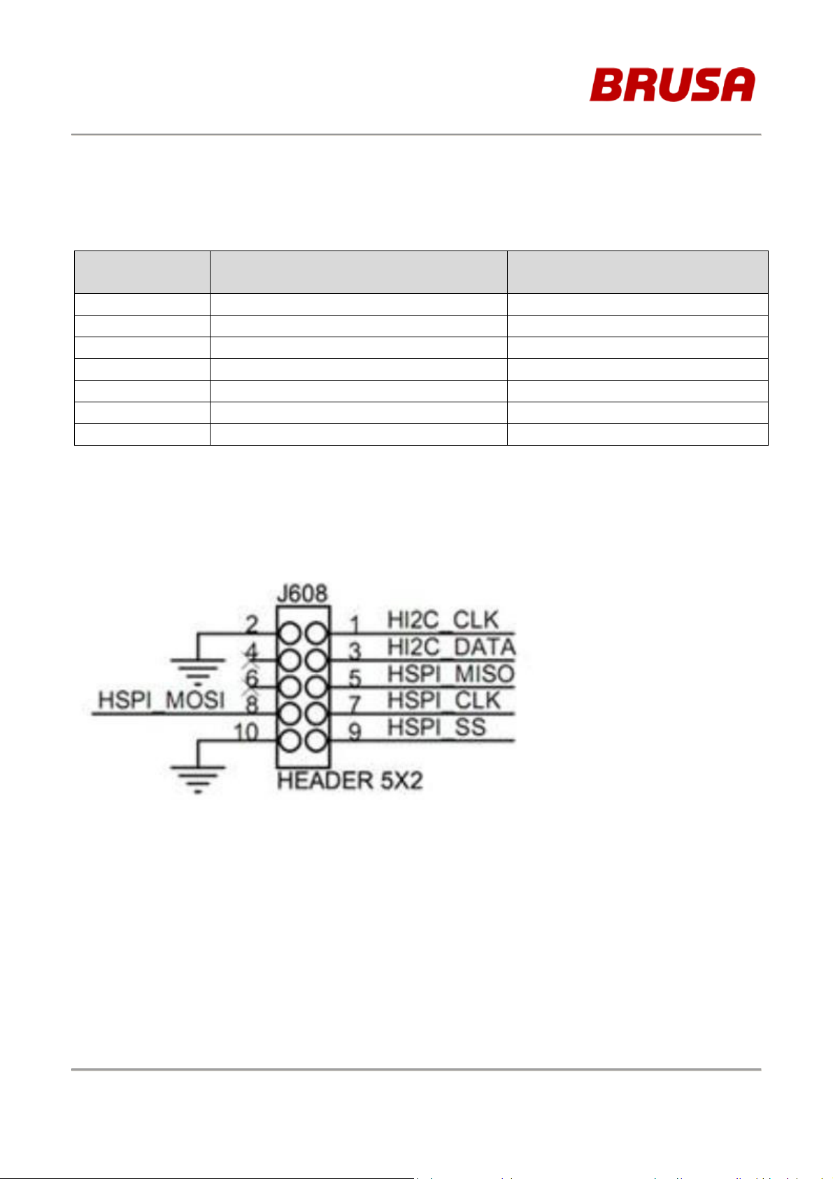
5.3 Aardvark Adapter
The configuration of the Aardvark Adapter connector is shown in Figure 9:
Figure 9: Aardvark Adapter Connector
User_Manual_Wlan_Module_Brusa_V1.4_final.docx
Page 12 of 35
BRUSA Elektronik AG
Neudorf 14,
CH–9466 Sennwald
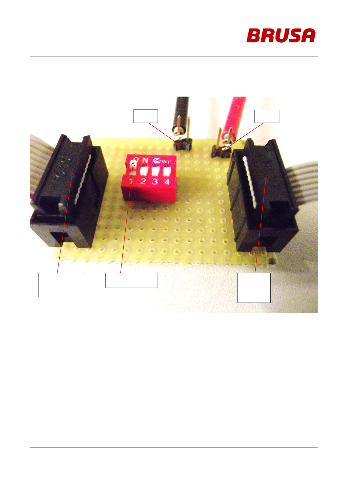
5.4 Adapter Board
Use the adapter board to connect the Wlan Module to the I2C adapter shown in Figure 10:
Aardvark
I2C plug
GND
Reset switch
3,4V
Wlan
module
plug
Figure 10: Adapter board
User_Manual_Wlan_Module_Brusa_V1.4_final.docx
Page 13 of 35

adapter
BRUSA Elektronik AG
Neudorf 14,
CH–9466 Sennwald
U.FL jack for
conducted
measurement
Aardvark
I2C
Figure 11: Photo documentation of Test Setup
Adapter
board
Wlan
module
User_Manual_Wlan_Module_Brusa_V1.4_final.docx
Page 14 of 35

BRUSA Elektronik AG
Neudorf 14,
CH–9466 Sennwald
5.5 Initial Startup
5.5.1 Hardware Steps
- Connect the module via Aardvark adapter and adapter board to the Laptop
(see Figure 11)
- Turn the reset switch in position “ON” (Reset inactiv) (see Figure 10)
5.5.2 Software Steps
- Install TotalPhaseUSB-v2.12.exe
- Open the file nmiSampleApp.exe from the Atmel GUI WILC1000_r812
- Activate the communication between Wlan module and GUI by pressing the RUN
button (see Figure 12 step 1). The chip ID should appear. Current consumption
should be I=0,06A
If an error occurs the reset switch from Figure 10 must be switched “OFF” (Reset
activ) and “ON” again. Press RUN again and the chip ID should appear.
- Select Firmware burst_tx_firmware.bin and press Load Test Fw (see Figure 12
step 2). Current consumption should be I=0,10A.
User_Manual_Wlan_Module_Brusa_V1.4_final.docx
Page 15 of 35

BRUSA Elektronik AG
Neudorf 14,
CH–9466 Sennwald
Figure 12: Atmel GUI first steps
5.6 Transmitting and Receiving
The instructions from chapter 5.5 must be completed to start TX or RX sequence.
5.6.1 TX-Sequence
- Select the channel in the Tuner Settings (Ch.1 – Ch. 14). (see Figure 14)
- Select Tx rate in TX Test (see Figure 14, Figure 15, Figure 16). Tx rate can be
configured between 1 Mbps – 54 Mbps (IEEE 802.11b/g) and between MCS0 – MCS
7 (IEEE 802.11n). Transmitter performance is described in Figure 13.
User_Manual_Wlan_Module_Brusa_V1.4_final.docx
Page 16 of 35

BRUSA Elektronik AG
Neudorf 14,
CH–9466 Sennwald
Figure 13: Transmitter Performance
- Select Output Power in Tx Power Settings (seeFigure 14). Bypass mode shall be
selected in TX Gain Settings. Only the Digital Gain Steps are allowed to be
changed. According to 802.11 b, g, n different values must be choosen (see Figure
14, Figure 15, Figure 16). PPA Gain Steps (6dB) and PA Gain Steps (18dB) must
not be changed because these are fixed values from Atmel Firmware. By pressing
apply and read current power settings are confirmed.
- By pressing Start Tx (see Figure 14) the module is transmitting data according to the
settings made before.
If the TX test runs, the test has to be stopped by Stop Tx Button (Figure 14) before it is
allowed to change any TX-Settings.
User_Manual_Wlan_Module_Brusa_V1.4_final.docx
Page 17 of 35

BRUSA Elektronik AG
Neudorf 14,
CH–9466 Sennwald
Settings according to 802.11b, g, n Standard:
Figure 14: 802.11b (Tx Rate 11Mbps worst case)
User_Manual_Wlan_Module_Brusa_V1.4_final.docx
Page 18 of 35

BRUSA Elektronik AG
Neudorf 14,
CH–9466 Sennwald
Figure 15: 802.11g (Tx Rate 6Mbps worst case)
Figure 16: 802.11n (Tx Rate MCS0 worst case)
User_Manual_Wlan_Module_Brusa_V1.4_final.docx
Page 19 of 35
Standard
Data Rate
Channel
Digital Gain Steps
BRUSA Elektronik AG
Neudorf 14,
CH–9466 Sennwald
Following digital gains steps shall be applied:
802.11b 1 Mbps - 11Mbps 1-14 -10
802.11g 6Mbps – 54 Mbps 1-14 -8
802.11n MCS0 – MCS7 1-14 -8
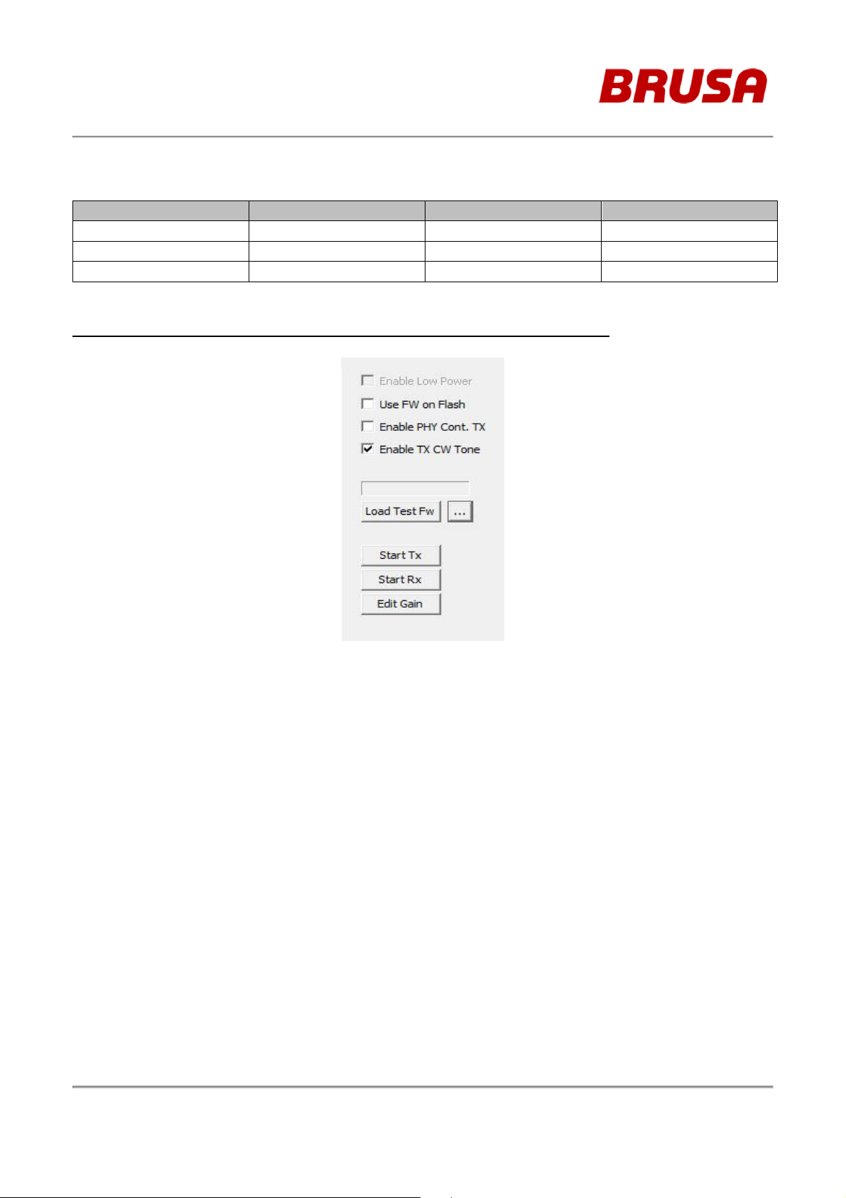
Table 8: Digital Gain Steps
For continuous unmodulated signal transmission use following settings:
Figure 17: CW Settings
User_Manual_Wlan_Module_Brusa_V1.4_final.docx
Page 20 of 35

BRUSA Elektronik AG
Neudorf 14,
CH–9466 Sennwald
5.6.2 RX-Sequence
One module can transmit data while another is receiving.
- Select the channel in the Tuner Settings (Ch.1 – Ch. 14).
- Select Tx rate and Duty Cycle in TX Test
- The quality of transmission is shown in RX Test. Loss of data is shown.
- By pressing Start Rx the module is receiving data according to the settings made
before.
Figure 18: RX - Sequence
If the RX test runs, the test has to be stopped by Stop Rx Button (see Figure 16 Start Rx
Button) before it is allowed to change any TX-Setting.
User_Manual_Wlan_Module_Brusa_V1.4_final.docx
Page 21 of 35

00-80-C2-5E-A2-B2
SPI
Generator
LAN
Koax
Koax
Koax
UUT
BRUSA Elektronik AG
Neudorf 14,
CH–9466 Sennwald
5.7 Adaptivity Testing
If the test is applicable use following setup:
Figure 19: Adaptivity Test Set-up example from ETSI en 300328
Atmel
SAM4S
IPERF-Client
WLAN
Module
MAC:
Coupler
USB
(Power 5V)
WLAN
Router
IP: 192.168.0.1
Figure 20: Adaptivity Test Set-up used for Certification Block Diagramm
IP: 192.168.0.102
Spectrum
Analyser
+
Signal
Test PC
IPERF-Server
User_Manual_Wlan_Module_Brusa_V1.4_final.docx
Page 22 of 35

BRUSA Elektronik AG
Neudorf 14,
CH–9466 Sennwald
Figure 21: Adaptivity Test Set-up used for Certification
User_Manual_Wlan_Module_Brusa_V1.4_final.docx
Page 23 of 35

BRUSA Elektronik AG
Neudorf 14,
CH–9466 Sennwald
5.7.1 UUT
Figure 22: Connection of DUT
Connections:
• UUT (WLAN Module) is connected to the SAM4S Connector EXT1 via 20Pin IDE
Cable (gray).
• U.FL Connector of DUT is connected to the Coupler via Coax Cable (gray).
Be carefully with the µ-FL connector!
• SAM4S is supplied with power (5V) via the Debug USB Connector. In our Set-up one
side of an USB Cabel (black) connected this Debug USB of the SAM4S and the other
side to the Test-PC.
User_Manual_Wlan_Module_Brusa_V1.4_final.docx
Page 24 of 35

BRUSA Elektronik AG
Neudorf 14,
CH–9466 Sennwald
5.7.2 Router
Figure 23: Connection of Router
Connections:
• One Antenna of the Router is connected to the Coupler via Coax Cable (blue).
• One LAN interface of the Router is connected to the LAN interface of the Test-PC via
Ethernet cable (red).
Configuration:
Activate WLAN on the Router (Switch)
Dual Band Selection:
x only work in 2.4GHz (802.11 a,b,g,n)
Wireless 2.4GHz:
Wireless Setting:
Network Name: atwinc1500
Region: Your Land (Germany)
Mode: 11bgn mixed
Channel with: 20 MHz
Channel: 1
x Enable SSID Broadcast
Wireless Security:
Version: WPA2-PSK
Encryption: AES
PSK Password:12345678
IP & Mac Binding:
Binding Settings:
ARP Binding: disable
00-80-C2-5E-A2-B2 to IP-address 192.168.0.100
00-22-33-44-55-66 to IP-address 192.168.0.101
MAC of Test-PC-Lan to IP-address 192.168.0.102
User_Manual_Wlan_Module_Brusa_V1.4_final.docx
Page 25 of 35

BRUSA Elektronik AG
Neudorf 14,
CH–9466 Sennwald
User_Manual_Wlan_Module_Brusa_V1.4_final.docx
Page 26 of 35

BRUSA Elektronik AG
Neudorf 14,
CH–9466 Sennwald
5.7.3 Test-PC
Connections:
• The LAN interface of the Test-PC is connected to one LAN interface of the Router via
Ethernet cable (red).
• In our Set-up an USB port of the Test-PC is connected to the Debug USB of the
SAM4S via USB Cabel (black) to provide the power for the SAM4S and the UUT.
5.7.4 Test Description
1. Remove USB-Cable from the PC.
2. Remove LAN-Cable from the PC
3. Start PC and read out Ethernet-Adapter LAN Connection MAC-address with the
command ipconfig –all in a command window.
4. Start the WLAN Router and wait until it is running.
5. Connect the PC via WLAN with the Router (AccessPoint atwinc1500 or TPLINK…)
6. Open internet explorer with addess 192.168.0.1.
7. Log into the router with User: admin and Password: admin.
8. Configure Router as given above.
9. Reboot the Router.
10. Disable WLAN on the PC.
11. Connect the LAN Cable from the PC.
12. Check Router settings.
13. Read out Ethernet-Adapter LAN Connection IP-address on the PC with the command
ipconfig –all in the command window. It must be 192.168.0.102.
14. Start the SAM4S with the UUT by connecting the USB-Cable to the PC.
15. Ping the UUT with the command ping 192.168.0.100.
16. Ping must be successful.
17. Disconnect the USB-Cable.
18. Ping the UUT with the command ping 192.168.0.100.
19. Ping must fail.
20. Connect the USB-Cable.
21. Ping the UUT with the command ping 192.168.0.100.
22. Ping must be successful.
23. Ping the PC with the command ping 192.168.0.102.
24. Ping must be successful.
25. Start Iperf server on the PC:
• Open Command window
• Switch to directory, where Iperf 2.0.5 is resided
• Start the server with the command iperf –s –i -t
26. Disconnect the USB-Cable.
27. Connect the USB-Cable.
28. Packets must be transferred. This can be observed in the comand window of the
Test-PC where the Iperf server was started.
User_Manual_Wlan_Module_Brusa_V1.4_final.docx
Page 27 of 35

BRUSA Elektronik AG
Neudorf 14,
CH–9466 Sennwald
Set standard, which should actual be tested, in the Router (Mode: 11b only / 11g only / 11n
only).
Reboot Router.
Restart UUT (disconnect and reconnect USB cable)
Perform adaptivity Test.
If packet transfer does not work after the test, restart the UUT and perfom the test again.
6 General Remarks
Once a module is configured to transmit or receive data it can be disconnected from the
Aardvark adapter. This allows to configure several modules with only one laptop and one
ATMEL GUI.
Note: The modules must be connected to power supply during the oberservation period!
User_Manual_Wlan_Module_Brusa_V1.4_final.docx
Page 28 of 35

BRUSA Elektronik AG
Neudorf 14,
CH–9466 Sennwald
7 Attachment
FCC and ISED Declarations
Compliance statement (part 15.19)
This device complies with part 15 of the FCC Rules and to RSS of Industry Canada.
Operation is subject to the following two conditions:
(1) this device may not cause harmful interference, and
(2) this device must accept any interference received, including interference that may cause undesired
operation.
Warning (part 15.21)
Changes or modifications not expressly approved by the party responsible for compliance could void
the user’s authority to operate the equipment.
Information to the User (Part 15.105 (b))
Note: This equipment has been tested and found to comply with the limits for a Class B digital device,
pursuant to part 15 of the FCC Rules. These limits are designed to provide reasonable protection
against harmful interference in a residential installation. This equipment generates, uses and can
radiate radio frequency energy and, if not installed and used in accordance with the instructions, may
cause harmful interference to radio communications. However, there is no guarantee that interference
will not occur in a particular installation. If this equipment does cause harmful interference to radio or
television reception, which can be determined by turning the equipment off and on, the user is
encouraged to try to correct the interference by one or more of the following measures:
--Reorient or relocate the receiving antenna.
--Increase the separation between the equipment and receiver.
--Connect the equipment into an outlet on a circuit different from that to
which the receiver is connected.
--Consult the dealer or an experienced radio/TV technician for help.
This Class B digital apparatus complies with Canadian ICES-003.
Cet appareil numérique de Classe B est conforme à la norme Canadienne ICES-003.
User_Manual_Wlan_Module_Brusa_V1.4_final.docx
Page 29 of 35
FCC ID:
2AK2AICS1WLAN
BRUSA Elektronik AG
Neudorf 14,
CH–9466 Sennwald
Installation Manual (FCC)
FCC ID of this module is as follows;
This Module has been certified to operate in the system as described in Chapter 3. The module has been
approved for fixed and mobile applications, with antenna distance >20 cm to any human body or any other
transmitter.
Antenna
This Module has been tested for FCC /ISED compliance with the antennas as described in this document. The
2.4-2.5 GHz patch antenna used is either mounted on the PCB of the Module or extended via 50 Ohm
impendence cable. Maximum antenna gain is 2dBi.
Antenna Type: Taoglas SWLP.2450.12.4.B.02
• Please refer to KDB 996369
• Please perform the antenna design that followed the specifications of the antenna.
Fine tuning of return loss etc. can be performed using a matching network.
However, it is required to check "Class1 change" and "Class2 change" which the authorities define then.
The concrete contents of a check are the following three points.
1) It is the same type as the antenna type of antenna specifications.
2) An antenna gain is lower than a gain given in antenna specifications.
3) The emission level is not getting worse.
Notice
For OEM integration only – device cannot be sold to general public.
The final product will include the following statements required by FCC/IC on the product and in the
Installation manual Notice.
Contains FCC ID: 2AK2AICS1WLAN
●Please describe the following warning to the manual.
This device complies with part 15 of the FCC Rules. Operation is subject to the following two conditions: (1)
This device may not cause harmful interference, and (2) this device must accept any interference received,
including interference that may cause undesired operation.
FCC CAUTION
Changes or modifications not expressly approved by the party responsible for compliance could void the
user’s authority to operate the equipment.
This transmitter must not be co-located or operated in conjunction with any other antenna or transmitter.
※When the product is small, as for these words mentioned above, the posting to a manual is possible.
●When installing it in a mobile equipment. Please describe the following warning to the manual.
This equipment complies with FCC radiation exposure limits set forth for an uncontrolled environment and
meets the FCC radio frequency (RF) Exposure Guidelines. This equipment should be installed and operated
keeping the radiator at least 20cm or more away from person’s body.
RF Exposure requirements are met when installed in mobile equipment.
This module cannot be installed in portable equipment without further testing and a change to FCC's grant of
authorization.
User_Manual_Wlan_Module_Brusa_V1.4_final.docx
Page 30 of 35

BRUSA Elektronik AG
Neudorf 14,
CH–9466 Sennwald
Note)
Portable equipment : Equipment for which the spaces between human body and antenna are used within
20cm.
Mobile equipment : Equipment used at position in which the spaces between human body and antenna
exceeded 20cm.
This device is intended only for OEM integrators under the following conditions:
The antenna must be installed such that 20 cm is maintained between the antenna and users, and
1) The transmitter module may not be co-located with any other transmitter or antenna.
2) The use of an antenna with gain less than 2 dBi
As long as 3 conditions above are met, further transmitter test will not be required. However, the OEM
integrator is still responsible for testing their end-product for any additional compliance requirements required
with this module installed
IMPORTANT NOTE: In the event that these conditions cannot be met (for example certain laptop
configurations or co-location with another transmitter), then the FCC authorization is no longer considered valid
and the FCC ID cannot be used on the final product. In these circumstances, the OEM integrator will be
responsible for re-evaluating the end product (including the transmitter) and obtaining a separate FCC
authorization.
End Product Labeling
This transmitter module is authorized only for use in device where the antenna may be installed such that 20
cm may be maintained between the antenna and users. The final end product must be labeled in a visible area
with the following: “Contains FCC ID: 2AK2AICS1WLAN”. The grantee's FCC ID can be used only when all
FCC compliance requirements are met.
Manual Information To the End User
The OEM integrator has to be aware not to provide information to the end user regarding how to install or
remove this RF module in the user’s manual of the end product which integrates this module.
The end user manual shall include all required regulatory information/warning as show in this manual.
Note: This equipment has been tested and found to comply with the limits for a Class B digital device, pursuant
to part 15 of the FCC Rules. These limits are designed to provide reasonable protection against harmful
interference in a residential installation. This equipment generates, uses and can radiate radio frequency
energy and, if not installed and used in accordance with the instructions, may cause harmful interference to
radio communications. However, there is no guarantee that interference will not occur in a particular
installation. If this equipment does cause harmful interference to radio or television reception, which can be
determined by turning the equipment off and on, the user is encouraged to try to correct the interference by one
or more of the following measures:
- Reorient or relocate the receiving antenna.
- Increase the separation between the equipment and receiver.
- Connect the equipment into an outlet on a circuit different from that to which the receiver is connected.
- Consult the dealer or an experienced radio/TV technician for help.
User_Manual_Wlan_Module_Brusa_V1.4_final.docx
Page 31 of 35

BRUSA Elektronik AG
Neudorf 14,
CH–9466 Sennwald
Installation Manual (IC)
IC No. of this device is as follows;
IC:
For OEM integration only – device cannot be sold to general public.
Therefore, we will ask OEM to include the following statements required by IC on the product and in the
installation manual Notice.
Contents
1) Theory of operation
2) Antenna
3) Notice
1. Theory of operation
Frequency of operation
2.4GHz 802.11b/g/n-HT20 2412MHz – 2462MHz (ch1 – ch11) Active Yes
Data transmission is always initiated by software, which is the passed down through the MAC, through the
digital and analog baseband, and finally to the RF chip. Several special packets are initiated by the MAC.
These are the only ways the digital baseband portion will turn on the RF transmitter, which it then turns off
at the end of the packet. Therefore, the transmitter will be on only while one of the aforementioned packets
is being transmitted. In other words, this device automatically discontinue transmission in case of either
absence of information to transmit or operational failure.
La transmission des données est toujours initiée par le logiciel, puis les données sont transmises par
'intermédiaire du MAC, par la bande de base numérique et analogique et, enfin, à la puce RF. Plusieurs
paquets spéciaux sont initiés par le MAC. Ce sont les seuls moyens pour qu'une partie de la bande de base
numérique active l'émetteur RF, puis désactive celui-ci à la fin du paquet. En conséquence, l'émetteur reste
uniquement activé lors de la transmission d'un des paquets susmentionnés. En d'autres termes, ce
dispositif interrompt automatiquement toute transmission en cas d'absence d'information à transmettre ou
de défaillance.
End users cannot modify the software because F/W & driver are installed in device.
Antenna
• Please refer to KDB 996369
• Please perform the antenna design that followed the specifications of the antenna.
Antenna Type: Taoglas SWLP.2450.12.4.B.02
Fine tuning of return loss etc. can be performed using a matching network.
However, it is required to check "Class1 change" and "Class2 change" which the authorities define then.
The concrete contents of a check are the following three points.
1) It is the same type as the antenna type of antenna specifications.
2) An antenna gain is lower than a gain given in antenna specifications.
3) The emission level is not getting worse.
Notice
For OEM integration only – device cannot be sold to general public.
Therefore we will ask OEM to include the following statements required by FCC/IC on the product and in the
Installation manual Notice.
Please describe the following warning on the final product which contains this module.
22375-ICS1WLAN
Scan
Ad-hoc
mode
User_Manual_Wlan_Module_Brusa_V1.4_final.docx
Page 32 of 35

This device is intended only for OEM integrators under the following conditions: (For module
3)
Cet appareil est conçu uniquement pour les intégrateurs OEM dans les conditions suivantes:
IMPORTANT NOTE:
BRUSA Elektronik AG
Neudorf 14,
CH–9466 Sennwald
Contains IC: 22375-ICS1WLAN
This device complies with Industry Canada’s licence-exempt RSSs. Operation is subject to the following two
conditions:
(1) This device may not cause interference; and
(2) This device must accept any interference, including interference that may cause undesired operation of
the device.
Le présent appareil est conforme aux CNR d’Industrie Canada applicables aux appareils radio exempts de
licence.
L’exploitation est autorisée aux deux conditions suivantes :
(1) l’appareil ne doit pas produire de brouillage;
(2) l’utilisateur de l’appareil doit accepter tout brouillage radioélectrique subi, même si le brouillage est
susceptible d’en compromettre le fonctionnement.
*When the product is small, as for these words mentioned above, the posting to a manual is possible.
●When installing it in a mobile equipment. Please describe the following warning to the manual.
This equipment complies with IC radiation exposure limits set forth for an uncontrolled environment and
meets RSS-102 of the IC radio frequency (RF) Exposure rules. This equipment should be installed and
operated keeping the radiator at least 20cm or more away from person’s body.
Cet équipement est conforme aux limites d’exposition aux rayonnements énoncées pour un environnement
non contrôlé et respecte les règles d’exposition aux fréquences radioélectriques (RF) CNR-102 de l’IC. Cet
équipement doit être installé et utilisé en gardant une distance de 20 cm ou plus entre le radiateur et le
corps humain.
RF Exposure requirements are met when installed in mobile equipment.
This module cannot be installed in portable equipment without further testing and a change to FCC's grant of
authorization.
Note)
Portable equipment : Equipment for which the spaces between human body and antenna are used within
20cm.
Mobile equipment : Equipment used at position in which the spaces between human body and antenna
exceeded 20cm.
device use)
1) The antenna must be installed such that 20 cm is maintained between the antenna and users, and
2) The transmitter module may not be co-located with any other transmitter or antenna.
The use of an antenna with gain less than 2dBi(2.4GHz)
As long as 3 conditions above are met, further transmitter test will not be required. However, the OEM
integrator is still responsible for testing their end-product for any additional compliance requirements required
with this module installed.
(Pour utilisation de dispositif module)
1) L'antenne doit être installée de telle sorte qu'une distance de 20 cm est respectée entre l'antenne et
les utilisateurs, et
2) Le module émetteur peut ne pas être coïmplanté avec un autre émetteur ou antenne.
User_Manual_Wlan_Module_Brusa_V1.4_final.docx
Page 33 of 35
End Product Labeling
Plaque signalétique du produit final
Manual Information To the End User
d'information à l'utilisateur final
BRUSA Elektronik AG
Neudorf 14,
CH–9466 Sennwald
In the event that these conditions cannot be met (for example certain laptop configurations or co-location
with another transmitter), then the Canada authorization is no longer considered valid and the IC ID cannot
be used on the final product. In these circumstances, the OEM integrator will be responsible for reevaluating the end product (including the transmitter) and obtaining a separate Canada authorization.
NOTE IMPORTANTE:
Dans le cas où ces conditions ne peuvent être satisfaites (par exemple pour certaines configurations
d'ordinateur portable ou de certaines co-localisation avec un autre émetteur), l'autorisation du Canada
n'est plus considéré comme valide et l'ID IC ne peut pas être utilisé sur le produit final. Dans ces
circonstances, l'intégrateur OEM sera chargé de réévaluer le produit final (y compris l'émetteur) et
'obtention d'une autorisation distincte au Canada.
This transmitter module is authorized only for use in device where the antenna may be installed such that
20 cm may be maintained between the antenna and users. The final end product must be labeled
in a visible area with the following: “Contains IC: - ”.
Ce module émetteur est autorisé uniquement pour une utilisation dans un dispositif où l'antenne peut
être installée de telle sorte qu'une distance de 20cm peut être maintenue entre l'antenne et les
utilisateurs. Le produit final doit être étiqueté dans un endroit visible avec l'inscription suivante:
"Contient des IC: - ”.
The OEM integrator has to be aware not to provide information to the end user regarding how to install or
remove this RF module in the user’s manual of the end product which integrates this module.
The end user manual shall include all required regulatory information/warning as show in this manual.
Manuel
L'intégrateur OEM doit être conscient de ne pas fournir des informations à l'utilisateur final quant à la
façon d'installer ou de supprimer ce module RF dans le manuel de l'utilisateur du produit final qui intègre
ce module.
Le manuel de l'utilisateur final doit inclure toutes les informations réglementaires requises et
avertissements comme indiqué dans ce manuel.
User_Manual_Wlan_Module_Brusa_V1.4_final.docx
Page 34 of 35

BRUSA Elektronik AG
Neudorf 14,
CH–9466 Sennwald
8 List of Figures
Figure 1: System description .................................................................................................. 4
Figure 2: Block diagram ATWINC1000B_MUT ...................................................................... 5
Figure 3: Wlan module top view ............................................................................................. 5
Figure 4: Wlan modules top view............................................................................................ 7
Figure 5: Wlan modules bottom view ...................................................................................... 7
Figure 6: DuT test setup ......................................................................................................... 8
Figure 7: Atmel GUI .............................................................................................................. 10
Figure 8: Aardvark I2C adapter ............................................................................................ 11
Figure 9: Aardvark Adapter Connector ................................................................................. 12
Figure 10: Adapter board ...................................................................................................... 13
Figure 11: Photo documentation of Test Setup .................................................................... 14
Figure 12: Atmel GUI first steps............................................................................................ 16
Figure 13: Transmitter Performance ..................................................................................... 17
Figure 14: 802.11b (Tx Rate 11Mbps worst case) ................................................................ 18
Figure 15: 802.11g (Tx Rate 6Mbps worst case) .................................................................. 19
Figure 16: 802.11n (Tx Rate MCS0 worst case) .................................................................. 19
Figure 17: CW Settings ........................................................................................................ 20
Figure 18: RX - Sequence .................................................................................................... 21
Figure 19: Adaptivity Test Set-up example from ETSI en 300328 ........................................ 22
Figure 20: Adaptivity Test Set-up used for Certification Block Diagramm ............................ 22
Figure 21: Adaptivity Test Set-up used for Certification ........................................................ 23
Figure 22: Connection of DUT .............................................................................................. 24
Figure 23: Connection of Router........................................................................................... 25
9 List of Tables
Table 1: Change index ........................................................................................................... 3
Table 2: List of abbreviations .................................................................................................. 3
Table 3: Module pin description .............................................................................................. 6
Table 4: Normal test conditions .............................................................................................. 9
Table 5: Extreme test conditions ............................................................................................ 9
Table 6: Channel plan WLAN standard 802.11b/g/n ............................................................ 10
Table 7: Module Configuration.............................................................................................. 12
Table 8: Digital Gain Steps ................................................................................................... 20
User_Manual_Wlan_Module_Brusa_V1.4_final.docx
Page 35 of 35
 Loading...