


OPERATION MANUAL
YSTEM ICS115
-
MAINTENANCE
Translation of original operati o n manual (English)
Read carefully before use! Keep safe for later reference!
INDUCTIVE CHARGIN G S
- INDUCTIVE CHARGING SYSTEM ICS115
FOR INSTALLATION – OPERATION –
www.brusa.biz
BRUSA Elektronik AG
Neudorf 14
CH–9466 Sennwald
+41 81 758 19 00

IMPRINT
Title
O
Publisher
BRUSA
Neudorf 14
CH
T +41
F +41
www.brusa.biz
info@brusa.biz
Managing Director: Josef Brusa
Valid for
ICS115 (2017)
Edition
1
st
Number
07/2018
Date of Issue
15.02.2018
Online version
Can be found at www.brusa.biz
Copyright
©
The copyright of this document lies with BRUSA Elektronik AG. The content of this document must
not be passed on to third parties
Elektronik AG. All technical specifications, drawings and photos used are protected by copyright.
The violation of the copyrights represents a criminal offence!
Updates
Due to the technical further development of our products, we reserve the right to make
constructional changes. Any
through exchange of
the relevant pages or revision of the electronic data carrier.
Writing style
For reasons of better readability, the simultaneous use of feminine and masculine linguistic forms is
disp
Creator / Author
Pirmin Bader, Sina Kaufmann, Josef Olliges
2.0
24.02.2017
Sina Kaufmann
Redesign of the documentation
3.0
11.04.2017
Josef Olliges
Integration of review comments
6
30.10.2017
Josef Olliges
Review comments Zollner integrated, Update GPM-B4
PERATION MANUAL INDUCTIVE CHARGING SYSTEM ICS115
Elektronik AG
–9466 Sennwald
8175 819–00
8175 819–99
Edition
2017 – 2018 BRUSA Elektronik AG
– even in extracts – without the written authorization of BRUSA
changes will be notified in the individual manuals
ensed with. All personal designations are always applicable for both genders.
REVISION INDEX
REVISION DATE NAME CHANGE
1.0 07.02.2017 Pirmin Bader Technical documentation based on the B3 prototype stage
4 03.05.2017 Josef Olliges Integration of review comments BMW, notes from risk
analysis
5 18.07.2017 Josef Olliges Review comments Daimler, BMW integrated
2
Operation Manual
Inductive Charging System
ICS115

7 15.02.2018 Josef Olliges Review comments Approval
TABLE OF CONTENTS
1 List of Abbreviations ....................................................................................................................... 7
2 Foreword .......................................................................................................................................... 8
2.1 Content and Scope of this Manual .............................................................................................. 8
2.2 Requirements for handling the User Manual ............................................................................... 8
3 Identification of the Product ICS .................................................................................................... 9
3.1 Product Identification .................................................................................................................. 9
3.2 Explanation of the code for the product identification .................................................................. 9
3.3 Service- and Contact Data ....................................................................................................... 10
3.4 Scope of Supply ....................................................................................................................... 11
4 Product Description of the ICS ..................................................................................................... 12
4.1 Scope of Application ................................................................................................................. 12
4.1.1 User Description ................................................................................................................ 12
4.1.2 Health Hazards ................................................................................................................. 12
4.1.3 Proper Intended Use ......................................................................................................... 13
4.1.4 Proper Intended Application .............................................................................................. 13
4.1.5 Improper Use .................................................................................................................... 13
4.1.6 Delimitation ....................................................................................................................... 14
4.2 Functionality ............................................................................................................................. 14
4.2.1 Energy Efficiency .............................................................................................................. 15
4.3 Requirements of the ICS .......................................................................................................... 15
4.4 Emissions ................................................................................................................................. 15
4.5 Electromagnetic Compatibility .................................................................................................. 15
5 Safety and Warning Signs ............................................................................................................ 16
5.1 Symbols and their Meaning ...................................................................................................... 16
5.2 Safety Instructions and Danger Levels ..................................................................................... 17
5.3 Generally Applicable Safety Instructions .................................................................................. 19
5.3.1 Safety Instructions for Thermal Hazards ............................................................................ 19
Operation Manual
Inductive Charging System
ICS115
3

5.3.2 Safety Instructions for Electrical Hazards .......................................................................... 19
5.3.3 Safety Instructions for Handling and Operation ................................................................. 20
5.4 Safety Equipment / Power Limitations ...................................................................................... 22
5.4.1 Overvoltage Protection ...................................................................................................... 22
5.4.2 Mains Protection Input Current .......................................................................................... 22
5.4.3 Overcurrent Protection ...................................................................................................... 22
5.4.4 Thermal Overload Protection (Derating) ............................................................................ 23
5.4.5 HV Interlock....................................................................................................................... 23
5.4.6 Living Object Detection (LOD) ........................................................................................... 23
5.4.7 Foreign Object Detection (FOD) ........................................................................................ 24
5.4.8 Control of the Efficiency .................................................................................................... 24
5.4.9 Enabling the Positioning .................................................................................................... 25
5.4.10 Automatic Shutdown of the Charging Operation ............................................................ 25
5.5 Warnings .................................................................................................................................. 26
5.5.1 Warnings ........................................................................................................................... 26
6 Commissioning and Use of the ICS ............................................................................................. 27
6.1 Installation of the GPM and Commissioning ............................................................................. 27
7 Control and Operation .................................................................................................................. 30
7.1 Use of the CPM and the GPM .................................................................................................. 30
7.2 Use of the Charging Function of the ICS .................................................................................. 30
7.3 Displays and Signals ................................................................................................................ 31
7.3.1 LED Display ...................................................................................................................... 31
7.4 GPM Cooling System Fan ........................................................................................................ 34
7.5 Emergency Situations .............................................................................................................. 34
7.6 Troubleshooting by the User .................................................................................................... 35
8 Maintenance .................................................................................................................................. 36
8.1 Cleanliness............................................................................................................................... 37
8.1.1 Cleanliness of the CPM ..................................................................................................... 37
8.1.2 Cleanliness of the GPM ..................................................................................................... 37
8.2 Behavior after a vehicle accident .............................................................................................. 38
9 Deinstallation ................................................................................................................................. 38
10 Disposal ...................................................................................................................................... 38
10.1 Notes for Customer Service .................................................................................................. 38
Operation Manual
Inductive Charging System
4
ICS115

11 Legal Notices ............................................................................................................................. 39
11.1 Warranty ............................................................................................................................... 39
11.2 Company Names .................................................................................................................. 39
12 Annex A1 .................................................................................................................................... 40
12.1 Technical Specifications of the ICS ....................................................................................... 40
12.1.1 Emissions ...................................................................................................................... 40
12.1.2 Dimensions and Center of Gravity ................................................................................. 40
12.1.3 Dimensions CPM [m m] .................................................................................................... 1
12.1.4 Center of Gravity CPM [mm] .......................................................................................... 42
12.2 Technical Data ...................................................................................................................... 43
12.2.1 Conditions for Storage and Transport of the ICS ........................................................... 44
12.2.2 Conditions for Operation of the ICS ............................................................................... 44
12.2.3 Mechanical Data of the CPM ......................................................................................... 45
12.2.4 Mechanical Data of the GPM ......................................................................................... 45
12.3 Requirements on Specialist Personnel ................................................................................. 45
12.3.1 Specialist Requirements ................................................................................................ 45
12.3.2 Health-related Requirements ......................................................................................... 45
12.4 Information about Protective Equipment ............................................................................... 45
12.4.1 Protective Equipment during Transport and Storage ...................................................... 45
12.4.2 Protective Equipment during Installation ........................................................................ 46
12.4.3 Protective Equipment during Operation ......................................................................... 46
12.4.4 Protective Equipment during Disposal / Deinstallation ................................................... 46
12.5 Preparation of the ICS for Use .............................................................................................. 46
12.5.1 Installation Information ................................................................................................... 46
12.5.2 Placement of the GPM ................................................................................................... 46
12.5.3 Alignment of GPM to CPM ............................................................................................. 46
12.5.4 Optional Installation of the GPM with Mounting Rails ..................................................... 48
12.5.5 Line Connections CPM .................................................................................................. 50
12.5.6 Line Connections GPM .................................................................................................. 50
12.5.7 Planning the Assembly and Installation of the ICS ......................................................... 52
Planning the assembly and installation of the CPM, see Annex 12.7.4. ........................................... 52
12.5.8 Transport and Storage ................................................................................................... 52
12.6 Deinstallation of the GPM ..................................................................................................... 54
Operation Manual
Inductive Charging System
ICS115
5

12.6.1 Procedure for the Deinstallation of the GPM (Information for Customer Service): .......... 54
12.7 Vehicle Integration of the CPM ............................................................................................. 55
12.7.1 Installation Information ................................................................................................... 55
12.7.2 Mounting the CPM ......................................................................................................... 55
12.7.3 Line Connections CPM .................................................................................................. 56
12.7.4 Planning the Assembly and Installation of the CPM ....................................................... 60
12.7.5 Transport and Storage of the CPM ................................................................................ 60
12.7.6 Installation of the CPM ................................................................................................... 61
12.7.7 Deinstallation of the CPM .............................................................................................. 62
13 Annex A2 .................................................................................................................................... 64
13.1 Standards and Legal Requirements ...................................................................................... 64
13.2 DECLARATIONS OF CONFORMITY ................................................................................... 65
13.2.1 SIMPLIFIED EU-DECLARAT IO N OF CONFORMITY ICS115 ....................................... 65
13.2.2 SIMPLIFIED EU-DECLARAT IO N OF CONFORMITY ICS1-WLAN-ATWILC-MU-D ....... 65
14 Index ........................................................................................................................................... 66
15 Glossary ..................................................................................................................................... 68
Operation Manual
Inductive Charging System
6
ICS115

AC
Alternating Current
ICSP
ICS Primary (GPM)
B [T]
ICSS
C [F]
Electrical capacity C in Farad F
LOD
Living Object Detection
CAN
Controller Area Network
LV
Low Voltage
CPM
Car Pad Module
OEM
Original Equipment Manufacturer
DC
P [W]
EMC
ElectroMagnetic Compatibility
R [Ω]
Electrical Resistance in the unit Ohm Ω
f [Hz]
Frequency f in Hertz Hz
RCD
Residual Current Device
FW
Firmware
SSID
Service Set IDentifier
GPM
Ground Pad Module
SW
Software
HV
High Voltage
t [s]
Time t in second s
I [A]
T [°C]
ICS
Inductive Charging System (CPM+GPM)
U [V]
Electrical vo lta g e U in Vo lt V
1 List of Abbreviations
In the course of this manual sever al trade-specific abbr eviations are used. An overv iew as well as their meanings
can be found in the following table:
ABB. DESCRIPTION ABB. DESCRIPTION
FOD
Magnetic flux density B in Tesla T
Direct Current
Foreign Object Detection
Electrical Current Intensity I in Ampere A
s [m]
ICS Secondary (CPM)
Power P in Watt W
Distance s in Meter m
Temperature T in degrees Celsius °C
Operation Manual
Inductive Charging System
ICS115
7

The completeness
2 Foreword
Valued Customer!
With the BRUSA Inducti ve Charging System Model ICS115 you h ave p urchased an induc tiv e charg ing s ystem with
the latest technolog y. Model ICS115 is an inductive chargi ng system of the 1
voltage battery, whic h is s ubs equentl y abbr eviated t o I CS. Sinc e it c oncerns hig h-performance electronic s de vices,
we expect particular caution whe n deal ing w ith it as well as when hand l ing it!
Read through this manual carefully – in particular the chapter entitled Safety and Warning Signs – before you
install the device or perform other work on it!
st
Generation for vehicles with high-
2.1 Content and Scope of this Manual
INFORMATION
In order to successfully commission the s ystem, you require this user manual.
and topicality is ensur ed with provision of the custom er package. Updates of individua l documents
are performed automatically and are visible in a history.
This documentation c onveys to th e reader an o verview of all the work steps required for the insta llation as well as
operation of the system and the safety measures necessary for this.
The specified operation- and safety instructions mus t be observed precisely, in order to continuousl y ensure the
function of the system.
The customer package contains the following registers:
Inductive charging system (ICS), consisting of Ground Pad Module (GPM) and Car Pad Module (CPM)
User manual
2.2 Requirements for handling the User Manual
The user manual must be read and understood by all persons who work with or use the ICS.
All safety instructions at the beginning of a cha pter are valid in equal m easure for all subsequent an d associated
subchapters following the chapter.
As user and also as custom er service of the ICS, familiari ze yourself with the user manual, so tha t you have fast
access to required information. Keep the user manual safe for later reference. Select an appropriate storage
location, so that the user manual is ready to hand and easy to find.
Operation Manual
8
Inductive Charging System
ICS115

ICSS115-U0-01X-Xxx (CPM, 2-HV-Connectors)
3 Identification of the Produc t ICS
3.1 Product Identification
This manual is valid exclusively for the devices listed in the following table:
ICS1 WITH THE FOLLOWING DEVICE DESIGNATIONS
ICSP11W-U0-01X-Xxx (GPM)
3.2 Explanation of the code for the product identification
The breakdown of the device designation for the complete system, the GPM and the CPM, is as follows:
GPM:
Operation Manual
Inductive Charging System
ICS115
9

Delivery
D, A, CH
BMW Customer Support
CPM:
3.3 Service- and Contact Data
TYPE OF INQUIRY COUNTRIES CONTACT DATA
Help and Support
Deinstallation and Disposal
D–80788 Munich
Germany
Tel: +49 89 1250-16000
kundenbetreuung@bmw.de
10
Operation Manual
Inductive Charging System
ICS115

QUANTITY
1
Ground Pad Module (GPM)
1
2
Car Pad Module (CPM)
1
3
Original Operation Manual
1
3.4 Scope of Supply
The following items are included in the scope of supply of the ICS system
DESCRIPTION
ILLUSTRATION
Operation Manual
Inductive Charging System
ICS115
11

Note:
The Car Pad Modules of th e possib le var iants f rom chapter
function with all Ground Pad Modu les
(GPM) of the ICS.
Risk of injury from electromagnetic field!
With inductive charging an electromagnetic field is generated under the vehicle.
Cardiac pacemakers and medical implants can be affected.
Do not reach underneath the vehicle or perform maintenance work during the charging process.
4 P roduct Description of the ICS
4.1 Scope of Application
The ICS consists of t wo separate devices. The Gr ound Pad Module (GPM) thereb y forms that part connected to
the power supply net work , which trans mits the en ergy to th e Car Pa d Module (CPM) int egrated i n the veh icle. T he
communication between GPM and CPM is automated and takes place via WLAN.
NOTE
3.1
4.1.1 User Description
The user group of the system ICS includ es a ll per sons who are able to operate a v ehic le. T he us er of the system is
responsible for the observance of and com pliance with the saf ety instructions conta ined in this user m anual. The
user is also respons ible, that persons in his environment, in particular all per sons who come int o contact with the
ICS, are knowledgeab le of and familiar with the safety instructions in this user manual. The user must indicate
possible hazards d ue to the IC S to o ther persons . H e m ust ther eb y ensure, that indi vidual, part icularl y enda ngere d
persons, e.g. children and disabled persons, have understood the safety instructions – or on the other hand
ensure, that access to the ICS is not possible for these persons.
All activities that concern the installation, commissioning and deinstallation / disposal of the ICS may only be
performed by specialist personnel. The specialist personnel or qualified electricians must satisfy the specialist
requirements specified in chapter 12.3.
4.1.2 Health Hazards
WARNING
12
Operation Manual
Inductive Charging System
ICS115

The electromagnetic radiat ion of the ICS remains within the legall y permitted limits. During the charg ing process,
the following groups of people are exposed to increased health risks in the vicinity of the ICS:
People with active medical implants (e.g. cardiac pacemakers, defibrillators)
People with passive medical implants (e.g. stents)
People with electric ally conductive forei gn objects in their bod ies (e.g. metallic splinter s from accidents / war
injuries)
4.1.3 Proper Intended Use
It is not permitted to use the products in any way other than the intended way described in section 4.1.4.
4.1.4 Proper Intended Application
The ICS is a system for the cordless transmission of energy and is designed to be integrated in an electric or hybrid
vehicle with high-volta ge battery. The pr oduct ICS is designed exc lusively for us e under consider ation of th e limits
specified in chapter 12.2.1 and 12.2.2.
With a planned use in areas other than those previou sly defined, the purchas er shall be obliged t o coordinate this
accordingly in advance with the manufacturer and obtain a written release for this.
4.1.5 Improper Use
All applications that ar e not included in the intend ed u se des cribed by the m anuf acturer in 4.1.4 are to be re garde d
as improper use.
The device must not be used, in particular
for charging vehicles that do not use the ICS as charging function
for charging accumulators / batteries of devices, that are also based on an inductive charging function, e.g.
electric toothbrushes, Smartphones
to replace the function of an induction hob, e.g. heating meals by using pots / bowls / grilling appliances
for drying objects (e.g. skiing equipment) or living things (e.g. pets)
for the use for functions other than the function of charging, e.g. as seating surface or for sports activities,
such as skateboarding.
The following areas must not be used as charging station, i.e. for the installation of the GPM:
public parking places and parking lots
Under consideration of the proper intended uses specified in chapter 4.1.4, limits have been defined for the
storage, transport and oper ation of the ICS pro duct, see chapter 12.2.1 and 12.2.2. T he product m ust not be used
outside these limits within the respective life phases. Modification of products.
It is not permitted to undertake modifications to the product and then continue to use the product.
Operation Manual
Inductive Charging System
ICS115
13
4.1.6 Delimitation
This operation manua l d es c ribes the s af e han dl ing with the Inductive Char g in g S ystem in all phases of lif e. BR U SA
Elektronik AG accepts no liability for the incomplete passing o n of information fr om this document, in p articular to
those persons from the target group defined in chapter 4.1.1 and any damage resulting therefrom.
4.2 Functionality
The ICS consists of two separate devices. T he Ground Pad Module (GPM) th ereby forms that part conne cted to
the power supply network , which transmits the energy to the Car Pad M odule (CPM) integrated in the vehic le by
means of magnetic induction. The communication between GPM and CPM is automated and takes place via
WLAN.
Basically the charging process takes place in these steps:
• The vehicle parks over the GPM with the help of the positioning function with optimal coverage between
GPM and CPM.
• The charging process is started automatically from the vehicle and also ended automatically.
• After the charging process the battery is charged according to the charging time and the charging
efficiency. The vehicle is read y to use.
Operation Manual
Inductive Charging System
14
ICS115

4.2.1 Energy Efficiency
The energy efficiency is generally dependent on the parking position of the vehicle over the GPM during the
charging process. Max imum efficiency is ac hieved when you park in the optimal positi on range. The efficienc y of
the charging process d epends, among other things, on the param eters of the drive battery (e.g. perf ormance and
charging cycle) of the vehicle in which the ICS is installed.
4.3 Requirements of the ICS
The CPM is maintena nce-fr ee and does not requir e an y supply m aterials, suc h as coolan t, lubrica nts, etc . For the
cooling of the GPM, a ir circulation is a pr erequisite, in particular during the chargin g process. Regular cle aning of
the fan intake duct and keeping the GPM clean extends the service life of the charging system, see chapter 8.1.2.
4.4 Emissions
The ICS has a fan whic h causes a noise level during operation. No ha zardous chemical s ubstances are emitted.
The transmission of energy of the ICS as well as the positioning functionality are based on the principle of magnetic
induction. In addition WLAN is used for the communication between the two components CPM and GPM.
Associated with this are e missions due to electromagnet ic radiation. The charac teristic values of these em issions
are to be taken from Table 1: Emissions.
4.5 Electromagnetic Compatibility
The ICS system m eets the requirements on the electromagnetic e nvironmental compatibility without cons traints,
see No. 11 – 15, 22 in Table 3: Stan dards. Normall y no disturbances that unaccept ably impair the functio nality of
other electrical operating equipment are caused through the use of the ICS. Nevertheless, a disturbance of Comfort
Access Systems of adjacent vehicles cannot be excluded, since both systems are based on the use of WLAN.
Operation Manual
Inductive Charging System
ICS115
15

General prohibition
Attention high voltage
Switching prohibited
No access for people with cardiac
Warning of potentially explosive
Warning of dangers from batteries
Warning of non-ionizing radiation
Warning of the risk of fire
5 S a f e ty and Warning Signs
In this chapter you will fin d s afet y instruct ions that m us t be tak en int o cons iderat ion in a ll lif e phases of th e s ystem .
Read and observe thes e instructions witho ut fail, in order to saf eguard the safet y and the life of peop le as well as
avoid damage to the device!
5.1 Symbols and their Meaning
Various symbols are used throughout this manual. An overview as well as their meanings can be found in the
following tables:
PROHIBITORY SIGNS
SYMBOL DESCRIPTION SYMBOL DESCRIPTION
Touching prohibited
pacemakers or implanted defibrillators.
WARNING SIGNS
SYMBOL DESCRIPTION SYMBOL DESCRIPTION
General warning of a hazard point
environment
Warning of hot surface
Warning of magnetic field
Warning of electric shock
Warning of high electric voltage
Warning of hot surfaces
16
Operation Manual
Inductive Charging System
ICS115

MANDATORY SIGNS
Disconnect device
Disconnect device from the mains
Wear safety glasses
Wear protective gloves
Important information for the avoidance of
Important Information
This sign warns of serious, irreversible risks of injury with possible fatal consequences!
Avoid this danger by observing this notice!
This sign warns of a serious, but reversi b le risk of injury!
Avoid this danger by observing this notice!
This sign warns of a minor risk of injury!
Avoid this danger by observing this notice!
SYMBOL DESCRIPTION SYMBOL DESCRIPTION
INFORMATION SIGNS
SYMBOL DESCRIPTION SYMBOL DESCRIPTION
possible material damage
5.2 Safety Instructions and Danger Levels
DANGER
WARNING
CAUTION
NOTICE
This notice warns of possib le material damage, if the following instructions and work sequences are
not observed.
Operation Manual
Inductive Charging System
ICS115
17

This type of notice is used to communicate important information for the reader.
INFORMATION
18
Operation Manual
Inductive Charging System
ICS115

Explosive Environment!
Do not store
devices! The generation of sparks at the device connections can ignite these materials and lead to an
explosion!
Hot Surfaces!
The devices
with caution!
High Voltage!
Do not touch HV
beforehand!
The device may only be connected by a qualified electrician!
Do not bridge or bypass safety equipment under any circumstances! Resulting malfunctions can have
life
Overheating the cable!
Mains connection cables must not be operated coiled up. In the coiled up state the cable can ignite
due to a build
5.3 Generally Applicable Safety Instructions
5.3.1 Safety Instructions for Thermal Hazards
DANGER
Danger to life!
any highly flammable substances or combustible liquids in the immediate vicinity of the
CAUTION
Risk of burning!
generate high temperatures during operation! Therefore always touch them carefully and
5.3.2 Safety Instructions for Electrical Hazards
Danger to life!
-lines or HV-connections under any circumstances without ensuring zero voltage
-threatening consequences!
Risk of fire!
DANGER
CAUTION
-up of heat! Therefore basically uncoil the mains connection cable completely!
Operation Manual
Inductive Charging System
ICS115
19

Basically observe the following 5 safety rules when working on the HV network:
Completely de
Secure system against
switch against restarting with lockable cover cap.
Establish zero voltage with suitab le volta
Ground and short
Cover or cordon off adjacent live parts.
Danger of electric shock!
In the operating state the ICS is subjected to high voltages and currents. If the device is damaged it is
possible, that live components are exposed. People can come into contact with these components.
It is therefore absolutely imperative to operate the
which monitors exclusively the function of the GPM.
Heating of foreign objects during the indu ctive transmission of energy!
Electrically conducting objects inside the charging magnetic field can heat up considerably, and under
certain circumstances can lead to damage / ignition of other materials. Therefore during the charging
process
GPM Magnetic Field!
No person must connect a GPM to the power supply without knowing the safety
A GPM may only be connected to the power supply, when all persons who are
are aware of the potential dangers.
INFORMATION
-energize the system.
Switch off the ignition
Pull out service- / maintenance plug or switch off main battery switch
Remove fuse
restarting.
Keep ignition key secured against unauthorized access.
Keep service- / maintenance plug secured against unauthorized access or secure main battery
ge tester (observe voltage range!)
-circuit system.
5.3.3 Safety Instructions for Handling and Operation
DANGER
GPM via a separate residual current device (RCD),
WARNING
Risk of fire!
there must be no objects between CPM and GPM.
WARNING
Danger for living beings and objects!
- and warning signs.
working near the GPM
20
Inductive Charging System
Operation Manual
ICS115

Strong magnetic field (non-ionizing radiation)!
Effect on living beings!
During
the limits for long
In order to exclude acute effects, such as muscle
damage, no
charging
In addition, jewelry (rings, wristwatches, etc.) can heat up considerably and become damaged or lead
to burns.
People with a cardiac pacemaker, implanted defibrillator or other implants should keep away from the
vicinity of the system during the charging
Keep animals away from the system during operation.
Damage to the HV-Battery:
Damage to the devices:
the charging process there is a strong magnetic field between CPM and GPM, which exceeds
process.
-term exposure of living beings.
body parts may get into and around the space between the GPM and CPM during the
DANGER
- and nerve stimulation, as well as conseque nti al
process.
NOTICE
Make sure, that the voltage ranges of the device and the HV-battery are identical!
Use only technically suitable and high-quality cabling! In case of uncertainties, please contact
BRUSA Elektronik AG beforehand at the manufacturer address specified in chapter 3.3.
NOTICE
Regularly check the GPM for defects and report defects or damage to your customer service.
A visibly damaged GPM must be replaced, in order to exclude the risk of injury. Do not touch
an obviously damaged GPM under any circumstances
Check generally when connecting the GPM, that the mains voltage is in the permissible range
(see chapter 4.2.1)!
Do not establish a low-resistance connection between the HV contacts, the housing- as well
as the LV-contacts under any circumstances! This leads to malfunctions and ultimately to the
destruction of the device!
The components of the ICS must not be opened under any circumstances!
Do not install and operate the GPM in the immediate vicinity of heat sources!
A high ambient temperature reduces the service life! Therefore continuously ensure for
sufficient cooling of the device!
Prevent any penetration of liquids in the device (e.g. during installation work)! The penetration
of liquids leads to a short circuit and subsequently to damage of the device!
If any liquid has entered, do not start the device again under any circumstances and contact
your customer service!
Operation Manual
Inductive Charging System
ICS115
21

Danger for persons due to strong magnetic field (non-ionizing radiation)!
5.4 Safety Equipment / Power Limitations
The charging system has several safety functions in order to avoid personal injur y and material damage during
commissioning, operation and maintenance of the system. Essentially these are
• Monitoring of the electrical limits
• Monitoring the operating temperatures
• Foreign object detection
• Living object detection
• Monitoring the efficiency
• Positioning only with connected HV-battery
DANGER
During the charging process it is not permitted under any circumstances to move/shift the GPM.
5.4.1 Overvoltage Protection
An overvoltage protec tion is integra ted in th e GPM, whic h continuous ly protec ts the device f rom overload dam age.
Overvoltages in the mains are detected by the fast sensor system and lead to the shutdown of the device.
An overvoltage protec tio n i s als o int egrat ed at the output side. B y m eans of the fas t s ensor system, overvoltages at
the HV-battery side (e.g. load shed ding or -fluctuations) are detected and lead to the shutdown of the charging
device.
5.4.2 Mains Protection Input Current
In the GPM the phase and the neu tral conductor are each protected b y a 25 A device fuse, in order to pr otect the
device and the electrical installations from damage due to overcurrent. If these fuses are defective, then the
relevant device must be sent back to the manufacturer (see manufacturer address in chapter 3.3 )! Contact
customer service.
5.4.3 Overcurrent Protection
NOTICE
It is prescribed to insert suitable overcurrent protection between CPM and HV-battery of the vehicle!
22
Operation Manual
Inductive Charging System
ICS115

An overcurrent protec tion is integrat ed in the CPM, which contin uously protects the chargin g device from overload
damage. Overcurr ents are detect ed by the f ast sensor system and, depending on the streng th, are either reduced
or lead to the shutdown of the charging process.
5.4.4 Thermal Overload Protection (Derating)
This safety equipment is s elf-protection of the system. If an internal component of the GPM or the C PM reaches a
defined temperature thr eshold, this causes a reduct ion of the charging capacit y (Derating), in order to protect the
component and consequently the device from damage due to overheating. As a result the capacity is reduced
proportional to the tem perature incre ase, in order to k eep the temper ature in the target range. The GP M regulates
the fan according to the temperature and ensures for additional cooling of the GPM.
The CPM and the GPM notif y their respective Derati ng-Status in the CAN, as well as the capacity reduct ion as
percentage. W hen the CPM goes into dera ting, the GPM reduces t he transmission power. If the measures tak en
above do not achieve the desired success, this leads to a shutdown of the charging system.
If the temperature is increased due to external effects independent of the charging system and the energy
transmission proces s, then the function of the seco ndary systems can also only b e used to a limited degree or
cease their function temporarily. This concerns the systems Positioning, WLAN, CAN and Diagnostic Function.
5.4.5 HV Interlock
The Interlock is a saf ety loop in the vehic le, which monitors the drive compone nts. On the CPM the HV -side plug
connections can be m onitored with this. The wiring of the Interlock-Pins is not func tionally relevant for the CPM,
however to guarantee the safety we definitely recommend using an interlock system!
5.4.6 Living Object Detection (LOD)
Operation Manual
Inductive Charging System
ICS115
DANGER
23

Danger for persons due to magnetic field (non-ionizing radiation)!
Danger for persons due to magnetic field (non-ionizing radiation)!
Danger for persons due to magnetic field (non-ionizing radiation)!
This function does not replace the attention of the user, to keep away from the charging station
during the charging process!
It can happen, that bod y parts or living beings are n ot detected by the LOD f unction and as a res ult
the protection from electromagnetic hazards is restricted!
The LOD function ensures, that body parts of people or animals are detected in the space between GPM and CPM.
This safety function protects people or animals from the dangers of the strong electromagnetic field, with the
charging process stopping when a living object is detected. It depends on the vehicle integration, whether the
charging process is resumed automatically as soon as the living object is no longer detected by the GPM.
5.4.7 Foreign Object Detection (FOD)
DANGER
This function does not replace the duty of the user, to keep the charging station free of foreign
objects!
It is possible, that cer tain foreign objects are not detected by the FOD functio n and as a result the
protection from thermal dangers is restricted!
The FOD function ensures, that there are no electr ical l y conduc t ing f orei gn obj ec t s on the GPM during the charging
process. Electrically conducting objects are relevant, as they can experience heating through electromagnetic
induction in the e lectromagnetic f ield. This function st ops the charging process when a foreign object is detected.
This safety function prevents a heating up of electrically conductive foreign objects during the charging process and
consequently reduces thermal dangers, such as e.g. fire or hot surfaces.
This function must be initialized during commissioning and after mains failures, see 7.3.1.2. In rare cases this
initializing can also be necessary during normal operation, see 7.3.1.2.
5.4.8 Control of the Efficiency
DANGER
This function does not replace the duty of the user, to keep the GPM free of foreign objects!
It is possible, that certain foreign objects are not detected due to the function of the Efficiency Control
and as a result the protection from thermal dangers is restricted!
If the efficiency falls below a certain limit value, e.g. due to the vehicle rolling away during charging, then the
charging process is shut down. As a r esult it is ens ured, that no energ y is transm itted to the system environment.
This safety function also pr events the he ating of electr ically conduc tive foreig n objects during the charging pr ocess
and thus reduces thermal dangers, such as e.g. fire or hot surfaces.
24
Operation Manual
Inductive Charging System
ICS115

5.4.9 Enabling the Positioning
With this safety function it is ensured, that no electrical voltage is present on the HV-outputs of the CPM (see
chapter 12.7.3), if the connections are not connected. Vice versa, voltage can only be present on the HVconnections of the CPM, if they are connected with a voltage source of 170 V (e.g. through connection to the
vehicle drive battery). This prevents people getting an electric shock by touching the connections.
5.4.10 Automatic Shutdown of the Charging Operation
With the occurrence of one of the following conditions, the ICS terminates the charging operation:
Detection of a foreign object (FOD) during charging
Detection of a living object (LOD) during charging
Overvoltage on the CPM HVDC-connector (> 450 V or greater than the specified maximum value)
Undervoltage on the CPM HVDC-connector (< 170 V)
Separation of the Interlock circuit
Missing CAN commanding to the CPM
Failure of the 12 V supply of the CPM
Short circuit on HVDC
Failure of the mains voltage
Voltage jumps on HVDC
Voltage drop AC-mains supply
Fault of the WLAN-connection
Overtemperature of the CPM (> 120°C)
Overtemperature of the GPM (> 85°C)
Load Dump (load shedding)
Charging capacity < 500 W
Mains failure (no independent restart of the energy transmission when the mains supply returns)
Communication failure between GPM and CPM
Communication failure bet ween CP M and veh icle-CAN (Vehicle-CAN, VCAN)
With a change of position of the CPM until the device is no longer physically able to transmit energy
Malfunction in the device
Operation Manual
Inductive Charging System
ICS115
25

5.5 Warnings
5.5.1 Warnings
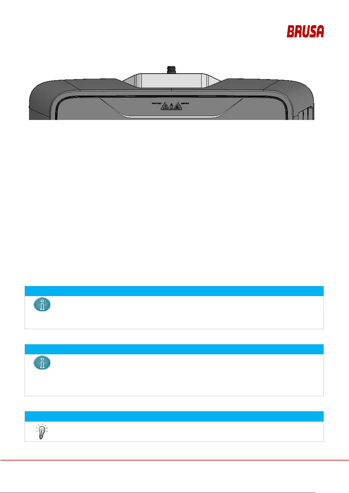
Warning signs are attach ed to the devices, which warn the operator of possible dangers. On the GPM there are
warning notices and a ratin g plate on the underside. In addition, encl osed in the GPM ser vice flap there is a rating
plate as well as inform ation about which types of cables are suitable for the co nnection of the power suppl y and
which temperature res istance is required for these cables. If one of these warning signs is missing or no longer
legible due to wear, it must be renewed immediately! To obtain an original label, please contact your customer
service!
Figure 1: Warning notice (colored) on GPM underside (left) and CPM (right)
26
Operation Manual
Inductive Charging System
ICS115
The installation of the GP M may only be carried out by a qualif ied electrician. In particu lar, country-
The GPM must be installed flat and level on the floor. A sinking of the GPM into the floor is not
Visually inspect the packaging material and in particular the GPM itself for damage before
Figure 2: Warning notice (black/white) on GPM top side
6 Com m issioning and Use of the ICS
The commissioning of the ICS assumes, that there is a suitable electrical connection available. The CPM is
mounted on the vehicle. T he GPM is insta lled b y the ser vice of the v ehicle m anufac turer at the i nstal lation lo cation .
The steps necessar y for this are des cribed in the anne x. Af ter the inst allation of the GPM it is c omm issioned b y the
service and thereby its functionality is explained.
6.1 Installation of the GPM and Commissioning
The installation of the CPM is the respo nsibilit y of the veh icle m anufactur er or his s ervice, see c hapter 12.7.6. The
installation of the G PM may only be carried o ut b y a q ualified electrician. T he commissioning s hou ld be u nd er taken
together with the user, in order to familiarize him with the functio n of the ICS, in particular with the LED flashing
patterns.
NOTICE
specific regulations f or electr ical lines an d instal lations ar e to be obs erved. For Am erica the Nationa l
Electrical Code NF PA 70 is to be com plied with, and in Cana da the Canadian E lectrical Code CSA
C22.1.
NOTICE
permitted. Protect the m ains connection cable with suitabl e floor mounted ducting resistant to overrolling. Due to its over all height, the GPM repr esents a tripping ha zard. Therefore do not insta ll the
GPM on footpaths or routes that you use frequently.
Ensure for sufficient lighting during installation, operation and deinstallation.
INFORMATION
installation. Ever y GPM undergo es a stric t quality- and func tion control before deli very. Howev er we
Operation Manual
Inductive Charging System
ICS115
27

have no influence on the long transport routes in some cases and the loading activities of our
Mains Voltage!
During installation of the GPM there exists a danger to life from electric shock, if the connection
For the installation you require:
Access to the circuit breakers with 16 A fuse and residual
During planning please no te, that the
GPM is monitored by a separate
residual current device. No other
device may be operated in parallel on the
supply line protected by the residual current
device.
nformation for the tra nsport
of the GPM in chapter
Observe the information for the
installation of the GPM in chapter
(Position to the CPM,
Requirements of the vehicle manufacturer,
Request of the user).
Connect the cable with the GPM.
Ensure safe and secure laying of the cable from the power
Avoid posing a tripping hazard due to
Use resources such as floor-mounted
ducting or similar to avoid tripping
products.
DANGER
sequence is not observed!
Make sure before commencing work, that the power connection is voltage-free!
Make sure, that ther e is an overcurrent protection device and a residual current dev ice (Type A) in
the connected current circ uit of the GPM! T he residual current dev ice may only monitor the f unction
of the GPM.
Check the residual curr ent dev ice by pressing the test butto n! Do not perform t he ins tal lat ion, if thes e
electrical safeguards are missing or are not functional!
Follow the prescribed work sequence without fail!
Do not act recklessly or impetuously under any circumstances!
WORK STEP ILLUSTRATION / OTHER INFO
current device (RCD) Type A
- Customary local mains cable of sufficient length with at least 1.5
- Floor-mounted ducting res istant against being run over for the
- GPM
Bring the GPM to the required des tination. Separate t he GPM from
the rest of the packaging material.
Determine the position of the GPM by applying the conditions for
the installation.
2
mm
line cross-section
protection of the mains cable.
Observe the i
12.5.8.2.
12.5.7.1
connection to the GPM.
protruding cable.
28
hazards.
Inductive Charging System
Operation Manual
ICS115

WORK STEP ILLUSTRATION / OTHER INFO
Make sure, that there are no foreign objects in the charging area.
Switch the power supply for the GPM on and check the residual
availability of the user for
instruction in the use of the device and the
dangers that can emanate from the ICS.
Initialize the foreign-/living object detection:
it again after 10sec. If there is no vehicle in the vicinity which is
The GPM now sends WLAN signals to vehicles in the reception
If the vehicle with functional CPM is in the transmit range of the
installed GPM, then the vehicle must be m ade known to the GPM.
practice this takes place as follows
In the vehicle display a list of all GPMs in the reception
Position the vehicle o ver the GPM, so that the CPM and GPM are
optimally overlaid. If the vehicle sends a request for charging and if
the request is success ful, then you see that on t he GPM b y the LED
flashing pattern, see
The preconditions for t he start of the c har ging
process are OEM
Wait a few minutes while t he vehicle charg es. Then place a sui table
foreign object (metallic, app rox .
GPM
and the LED on the GPM should flash, see
. After removing
the inserted object the charging process should be resumed, see
7.3.1.5
Remove the vehicle from the area in which char gin g is poss ible. T he
status of the GPM should c hange to the status CONNECTED, see
7.3.1.4
the GPM, or the GPM s witches to the status NO T CONNECTED, if
the vehicle should not have any W LAN rec eption fr om the GPM, s ee
7.3.1.3
Connect the cable with the power connection.
On the GPM the LED should not l ight up, in other words OF F, see
7.3.1.1.
current device. If the GPM is supplied with mains voltage, then as
next step the LED signals the initialization of the foreign-/living
object detection, see
Place an approx. 5cm large m etallic objec t on the GP M and rem ove
suitable for the ICS chargin g s ystem, then t he GPM fla shes with t he
appropriate pattern
range, but is not yet connected with any vehicle.
1.
range of the CPM is displayed.
2. The required GPM is selected
3. The password for the selected GPM is entered.
Once this step is suc cessfull y concluded, then th e LED of the GPM
flashes with the pattern CONNECTED, see 7.3.1.4
7.3.1.2.
7.3.1.3
In
:
Note the
7.3.1.5.
5cm diameter) in the space between
and CPM. The charging process should then be interrupted
7.3.1.7
.
, insofar as the vehi cle is still sensed in the transmit range of
Operation Manual
Inductive Charging System
ICS115
-specific.
29

The ICS has onl y one LED display, which signa ls important states of the GPM. Obs erve all safety
instructions and warnings in the user manual without fail!
Scrutinize the instructions of the positioning display in your vehicle!
Physical Limits. Within the octagon described above, energy is transmitted with a high level of
Take into consideration the properties and parameters of the CPM and GPM, if you have
modifications carried out on the vehicle or perform them yourself!
Please note, that material damage to the vehicle or ICS is possible, if modifications to the vehicle
(t
7 Cont rol and Operation
NOTICE
7.1 Use of the CPM and the GPM
The charging process between GPM and C PM functions autom atically and does not nee d to be controlled. Used
on its own, the CPM exec utes no function; without the pres ence of the CPM the GPM merely onl y detects foreign
objects and otherwise does not execute any function when used on its own.
7.2 Use of the Charging Function of the ICS
Observe the warnings in 5.3.3 Safety Instructions for Handling and Operation
NOTICE
It is possible, that strict compliance with the positioning leads to m aterial damage to the vehicle! A
faulty positioning display or incorrect position of the GPM, e.g. due to the GPM shifting on the
ground, can lead to damage to your vehicle during the parking process!
Therefore always obser ve the signals of the park ing assistance of your veh icle! Give these signals
precedence over the positioning signals of the ICS!
NOTICE
efficiency. Outside the octagon limitations in the charging performance are to be reckoned with:
- Reduced efficiency
- Reduced transmission power
- Reduced charging voltage range
- Increased charging time
NOTICE
uning, lowering the vehicle) are undertaken.
Inductive Charging System
30
Operation Manual
ICS115

WORK STEP ILLUSTRATION / OTHER INFO
1
Observe the instructions for keeping the GPM clean in
2
Position the CPM above the GPM or position
your vehicle with the help of the positioning
On the GPM the LED should flash with the
pattern according to
Observe the instructions. Avoid dam age to your veh i c le
3
Start the charging process by following the
instructions on the user interface of your
If the charging process does not start, follow the
off
on
Make sure, that the GPM is free of objects.
function.
7.3.1.4.
vehicle. On the GPM the L ED should f lash with
the pattern according to
7.3.1.5.
7.3 Displays and Signals
chapter 8.1.2.
due to positioning malfunctions.
troubleshooting instructions in chapter 7.6 or contact
customer service.
7.3.1 LED Display
On the service flap of the GPM there is an LED, which indicates the operating status and error states.
7.3.1.1 Status: Off
The GPM is without power or defective. After unpacking the GPM, the LEDs are off. Likewise after installation
before the circuit break er has been switched on. If the LEDs remain off after the GPM is work ing, then there is a
defect. In this cas e, ch eck that neither the c ircuit br eak er nor the r esidua l curr ent device inter rupt the p ower s uppl y
to the GPM.
Figure 3: Flashing pattern in status Off
7.3.1.2 Status: Initialization Foreign-/Living Object D etection
For safety reasons during running operation, the GPM monitors that there are no living or foreign objects between
GPM and CPM. For this safety function a re-initialization may be necessary. In the status Initialization Foreign/Living Object Detection, charging the vehicle is not possible, because the GPM can no longer safely evaluate,
whether an object is present or not.
If the GPM requires an initialization of the foreign-/living object detection, you recognize this by this flashing pattern:
Operation Manual
Inductive Charging System
ICS115
31

off
on
0,25s
0,25s
0,25s
0,25s
0,25s 4s
off
on
2s
0,1s
0,1s
2s
off
on
Figure 4: Flashing pattern in status Initialization Foreign-/Living Object Detection
In practice this initialization is carried out by making sure that there is no object lying on the GPM surface. Then
place an approx. 5cm large piece of metal (e.g. 5cm large steel disk, beverage can, etc.) on the GPM and remove
it again after 6-9sec. The initialization of the foreign-/living object detection is possibly required
• after the GPM is switched on or after a mains failure,
• during the operation
7.3.1.3 Status: Not Connected
The GPM is in this status, when the power supply for the GPM has been switched on, the initialization of the
foreign-/living object detection has already been performed, but there is not yet any vehicle nearby, which is
suitable for charging with the GPM.
Figure 5: Flashing pattern in status Not Connected
7.3.1.4 Status: Connected
If a suitable vehicle ( with CPM) is c onfigured f or charging with the GPM an d if this vehicle is near the GPM, then a
WLAN connection is estab lished between CPM and GPM. The c harging process is controlled autom atically from
the vehicle via this WLAN connection.
Figure 6: Flashing pattern in status Connected
32
Operation Manual
Inductive Charging System
ICS115

7.3.1.5 Status: Charging / Energy Transmission
off
on
2,5s
2,5s2,5s
2,5s
2,5s 2,5s
off
on
0,25s
0,25s 0,25s
0,25s
0,25s
0,25s 0,25s
0,25s
0,25s
0,25s 0,25s
0,25s
0,25s
off
on
0,25s
0,25s
0,25s
4s
If the vehicle (with C PM) is in the optimal park ing position , then the ch arging proc ess is started a utomaticall y. The
energy transmission from GPM to the vehicle is signaled by means of LED with this flashing pattern.
Figure 7: Flashing pattern in status Charging / Energy Transmission
7.3.1.6 Status: General Error
With an error the LED flas hes with this pattern. Atte mpt to rectif y the error as described in 7.6 Troubl eshooting by
the User.
Figure 8: Flashing pattern in status General Error
7.3.1.7 Status: Foreign Object Detected
If a foreign object is detected during char g ing, the n th e c hargi ng pr oc ess is inter r upte d f or safety reasons. The LED
signals this with this pat tern. In this case chec k the GPM and m ake s ure, that the GPM is free of f oreign obj ects of
any kind.
Figure 9: Flashing pattern in status Foreign Object Detected
Operation Manual
Inductive Charging System
ICS115
33

off
on
0,25s
0,25s
0,25s
0,25s
0,25s
0,25s 0,25s 4s
Development of smoke or fire in
the charging environment
1.
2. Remove yourself and if neces sary other persons immediately from the source
of the fire and from the surroundings! Do not use the vehicle in the charging
station for this!
3.
4.
5.
Feeling of numbness in the
extremities
1.
2.
3.
Feeling unwell
1.
2.
3.
If a foreign object is det ected incorrec tly, although the GPM surfac e is free, then a reset of the G PM is necess ary,
i.e. the GPM mus t be disconnected from the power supply until the LED goes out. After switching the GPM on
again, a renewed initializat ion of the FOD is possibly necessar y, see 7.3.1.2 Stat us: Initialization Foreign-/Living
Object Detection.
7.3.1.8 Status: Cooling Fan Blocked
The GPM is reliant on a sufficient circulation of air, in particular during the charging process. If the fan duct is
clogged, and the fan is bl ock ed, then you recog nize thi s on the L ED with th is pat t ern. In th is case pl ease che ck the
cooling duct and clean it as required.
Figure 10: Flashing pattern in status Fan Blocked
7.4 GPM Cooling System Fan
Noise can be caused by the cooling function of the fan. The device is protected f rom overheating by an internal
function. Please treat the fan with care and observe the instructions f or cleaning, see section 8.1 Cleanliness. In
particular clean the fan intake duct regularly. Do not use any high-pressure cleaner, such as e.g. Kärcher!
7.5 Emergency Situations
With the occurrence of emergenc y situatio ns, f ollow the c orres ponding s ituatio n descr iptions in th e table be lo w and
comply with the associated instruc tio ns!
SITUATION INSTRUCTIONS
Keep calm!
Fetch help. Call the fire department!
Keep other people away from the source of the fire!
Visit a doctor in order to exclude smoke poisoning!
Keep calm!
34
Remove yourself immediately from the charging environment!
Visit a doctor.
Keep calm!
Remove yourself immediately from the environment of the charging station!
Visit a doctor.
Operation Manual
Inductive Charging System
ICS115

7.6 Troubleshooting by the User
It is not possible t o position the
vehicle for a charging operation.
1.
whether your vehicle is switched on. The po sitio ning functi on onl y works
when readiness to drive is established. In addition the confirmation of your
consent for the charging operation is required via the interface of the vehicle.
2.
has shifted. If so, bring it bac k to that position, that
was determined in chapter
3.
r this, establish
whether the power suppl y for the GPM has been inter rupted by electrical safety
devices. If so, re-establish the power supply for the GPM, by switching on the
electrical safety device.
4. Check, whether the WLAN connection between CPM and
If necessary repeat the positioning process.
5
The charging operation is
aborted again immediately after
the start.
1. Check, whether the GP M is free of foreign objects. If necessary clear it, takin g
into consideration the information specified in chapter
2.
heck, whether the charging function has been and can be interrupted by
people or animals. If necessary, prevent the access to the charging station.
3. Check, whether the GPM can be supplied with power. For this, establish
whether the power suppl y for the GPM has been inter rupted by electrical safety
devices. If so, re-establish the power supply for the GPM, by switching on the
electrical safety device.
4. Check, whether the dif ference in height betwee n GPM and CPM has cha nged
in an inadmissible wa y, e.g. due to a gre at deal of snow on th e car tires or o n the
ground, on which the GPM is installed.
5.
For the following errors, limited troubleshooting can be undertaken by the user. The troubleshooting is to be
undertaken as described in this chapter. The user is forbidden to undertake further troubleshooting that goes
beyond the troubleshoot ing specified in this chapter. In the follo wing, situations are des cribed as can occur durin g
the operation. The tr oubleshooting is to be un dertaken and perform ed in the given order for ex actly that situation
description that applies to the current situation.
SITUATION TROUBLESHOOTING
Check,
Check , whether the GPM
12.5.1.
Check, whether the GPM can be supplied with power. Fo
GPM is faulty.
. If the error still occurs, contact customer service.
8.1.2.
C
If the error still occurs, contact customer service.
Operation Manual
Inductive Charging System
ICS115
35

The vehicle (the drive battery) is
not completely charged.
1.
complete charge of the battery was
sufficient. (Is the charging process resumed when you resume the charging
function?)
2. Check, whether the GPM and its immediate environment is free of foreign
objects. If necessar y clear it, tak ing into consideratio n the information specifie d in
chapter
. Perhaps the charging operation could not be completed in the
charging time provided due to the presence of
3. Check, whether the charging function has been and can be interrupted by
people or animals. If necessary, prevent the access to the charging station.
Perhaps the charging proc ess was stopped by a person or animal and theref ore
could not
4.
The vehicle (the drive battery) is
not completely charged,
although the charging operation
was indicated as completed.
1.
vehicle (e.g. radio, light, navigation?) were
switched on, so that after charging up, the drive battery was discharged again.
2.
The ICS System can no longer
be used / it is switched off.
1.
her the GPM can be supplied with power. For this, establish
whether the power suppl y for the GPM has been interrupted by electrical safet y
devices. If so, re-establish the power supply for the GPM, by switching on the
electrical safety device.
2.
Never perform maintenance measures during operation of the ICS!
During
the limits for long
In order to exclude acute effects, such as muscle
damage, no
charging
In addition, jewelry (rings, wristwatches, etc.) can heat up considerably and become damaged or lead
to burns.
People with a cardiac pacemaker
system during the charging
Keep animals away from the system during operation.
SITUATION TROUBLESHOOTING
Check, whether th e charging time for the
8.1.2
foreign objects.
be completed in the charging time provided.
If the error still occurs, contact customer service.
Check, whether consumers in the
If the error still occurs, contact customer service.
Check, whet
Contact customer service
8 Maintenance
DANGER
Strong magnetic field (non-ionizing radiation)!
Influence on electrically conductive obj ects!
36
the charging process there is a strong magnetic field between CPM and GPM, which exceeds
-term exposure of living beings.
- and nerve stimulation, as well as conseque nti al
body parts may get into and around the space between the GPM and CPM during the
process.
or implanted defibrillator should keep away from the vicinity of the
process.
Inductive Charging System
Operation Manual
ICS115
NOTICE
Apart from the cleaning in chapter 8.1.2 all maintenance measures may only be performed by
For the CPM regu lar c leaning by th e user is not i ntend ed and als o not perm itted. Non-obs ervanc e of
Do not perform cleaning during and imme d iately after the charging process!
Keep the GPM clean and remove objects in its close proximity, which would lie under the vehicle
during the charging process. In particular no cables may be routed over the GPM. During the
specialists!
Contact customer service to have measures carr ied out for the maintenance of the ICS! This way
you avoid material damage to the ICS or the loss of the warranty.
The ICS system consists of the components CPM and GPM. In the fram ework of the guarantee it is pos sible to
have these two com ponen ts ins pecte d b y specia lists, if failure s ymptom s ar e evident. C ont act cus tom er ser vice f or
this. The contact details can be found in chapter 3.3.
Consumables or individual replacement parts are not required or provided f or the CPM or the GPM of the IC S
system.
If a warranty case occurs , the respective components are to be rep laced exclusively by specialists . In particular,
renewed work for the installation of the components is also to be carried out by specialists. If individual components
have to be replaced, the de scr iptions for the pr eparat ion of the I CS for us e or for d einsta llation in ch apter
are to be observed for the removal of the old components and the installation of the new components.
6 resp. 9
8.1 Cleanliness
8.1.1 Cleanliness of the CPM
this notice can result in damage to the CPM.
8.1.2 Cleanliness of the GPM
charging process, objects in the charging area may have heated up. Touching these objects can lead
to injuries due to burning.
Deviation from recommended measures for cleaning can result in damage to the GPM.
NOTICE
CAUTION
NOTICE
During use the GPM must be kept c lean. It is recommended to keep the GPM clean by means of the following
measures:
Operation Manual
Inductive Charging System
ICS115
37

Manual clearing of the GPM surroundings
Sweeping off the GPM
Moist wiping of the GPM with a mild cleaning agent
Cleaning the fan intake duct
In particular the following measures should not be applied to keep the GPM clean:
High-pressure cleaner, e.g. Kärcher
(strong) chemical cleaning agent
Road sweeper
Snow plough
8.2 Behavior after a vehicle accident
After an accident with t he vehicle in which the C PM is installed, the CPM m ust be inspected for functionality by a
specialist.
9 Deinstallation
NOTICE
Measures for the deinstallation and disposal may only be performed by specialists!
Contact customer s ervice to have measures performed for the maintenance of t h e ICS! This way you
avoid material damage or dangers for nature and the environment!
The deinstallation of the GPM is described in chapter 12.7.7.
10 Disposal
The disposal of the IC S is carried out by custom er service after the deinstal lation of the system from the vehicle
(CPM) or from the charging station (GPM).
10.1 Notes for Customer Service
A basic prerequisite for the reuse and the recycling of used electronic devices is the correct disposal.
According to the EU-Direct ive 2012/19/ EU, since 24
together with the household waste, but m ust be collected and gat hered separately by a s pecialist company. The
disposal by a specialist com pany contributes significantl y towards avoiding dangers for people and nat ure. In the
case of disposal we therefore recommend that you contact a recognized specialist waste management company.
th
March 200 6 electrical dev ices may no longer be d isposed of
Operation Manual
Inductive Charging System
38
ICS115

11 Legal Notices
11.1 Warranty
For damage that occurs during proper intended use and despite observance of the safety instructions in this
document, BRUSA provides a warranty for the ICS. The warranty is in accordance with the provisions in our
currently valid General Terms and Conditions, which can be viewed at www.brusa.biz/support/agb.html
No warranty is provided for damage that can be traced back to improper use or non-observance of the safety
instructions.
11.2 Company Names
The company names mention ed in this operation manual are used exc lusively for identification and are ther efore
mentioned without consideration of a possibly existing patent- or trademark protection:
BMW
Daimler
.
Operation Manual
Inductive Charging System
ICS115
39

12 Annex A1
12.1 Technical Specifications of the ICS
12.1.1 Emissions
Table 1: Emissions
PARAMETER CHARACTERISTIC VALUE UNIT
Max. magnetic flux density between GPM and CPM 7*10-3 T
Magnetic flux density of the GPM at vehicle limitation 4.6*10-6 T
WLAN-Signal
- Frequency
- Max. t ransmit power 19 dBm
Positioning signal
- Frequency s
- Max. radiated magnetic field strength at 125 kHz
2.4
79 mW
125
17.5
GHz
kHz
dBµA/m
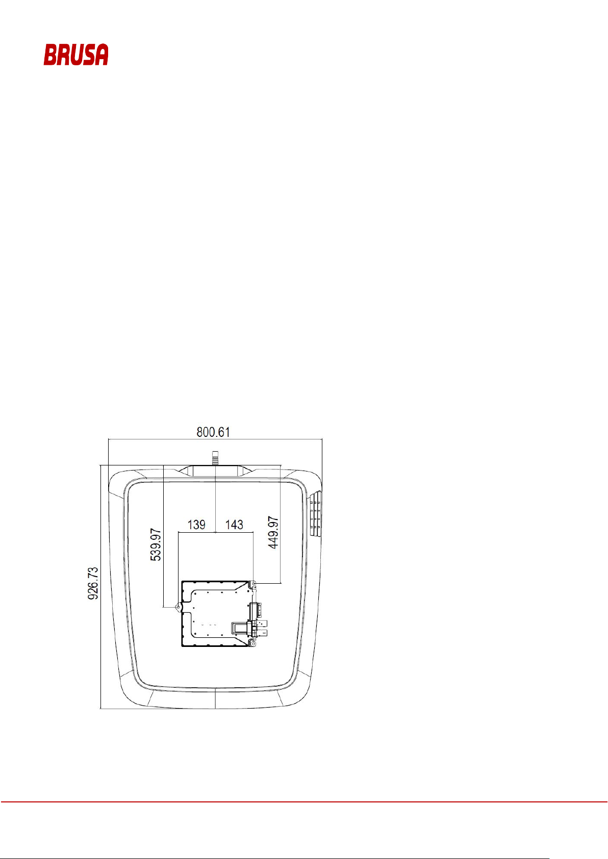
12.1.2 Dimensions and Center of Gravity
12.1.2.1 Dimensions GPM [mm]
Operation Manual
Inductive Charging System
40
ICS115

Intake duct
fan
Figure 11: Center of gravity of GPM with fan intake duct
Service flap
12.1.2.2 Center of Gravity GPM [mm]
12.1.3 Dimensions CPM [ mm]
with mains
cable
connection
Operation Manual
Inductive Charging System
ICS115
41
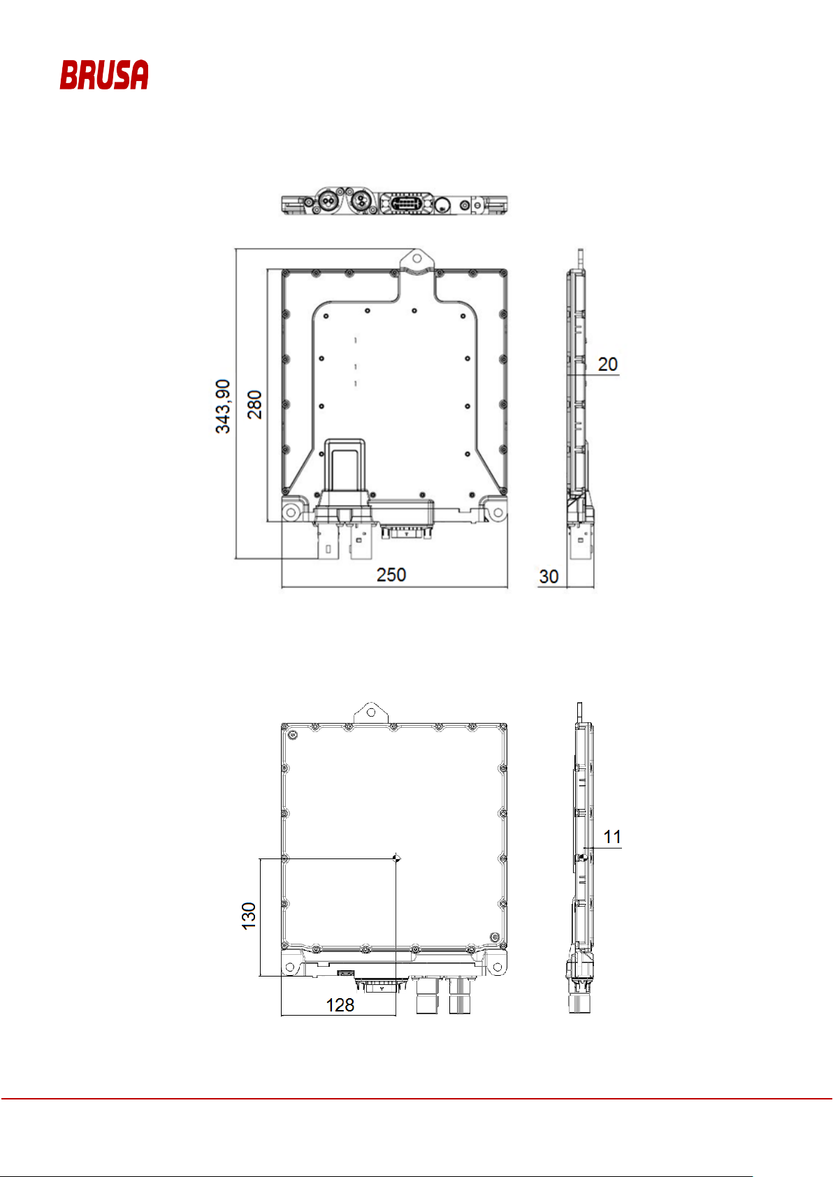
12.1.4 Center of Gravity CPM [mm]
Operation Manual
Inductive Charging System
42
ICS115

12.2 Technical Data
BASIC DATA ICS VALUE UNIT
Total weight approx. 52 kg
Rated input voltage (single-phase L1/N) 200 – 240 VAC
Rated input voltage (two-phase L1/L2) 100 – 120 VAC
Rated input frequency 50 – 60 Hz
Maximum input current 16 A
Max. input power 3600 W
Charging voltage 200 – 440 VDC
Max. c hargi ng current 12 ADC
Charging capacity 500 – 3200 W
Energy transmission frequency 81.38 – 90 kHz
Duration of a charging process Dependent on type of vehicle
Transmission frequency WLAN (ISM Band) 2.412 – 2.462 GHz
Max. t ransmit power WLAN 100 mW
Transmission frequency positioning 125 kHz
LV-wiring system CPM 9 – 16 VDC
LV-wiring system max. voltage CPM ( devi ce destruction) 27 VDC
IP protection class IP6K9K, IP65 Insulation class acc. EN 61140 Protection class I -
rms
BASIC MECHANICAL DATA MIN MAX UNIT
Height above ground GPM 0 0 mm
Height above ground CPM 100 160 mm
Operation Manual
Inductive Charging System
ICS115
43

Maximum offset GPM to CPM in travel direction (x-direction) -75 75 mm
Maximum offset GPM to CPM transverse to travel direction (y-direction) -150 150 mm
Above specified applies, if 0 |x| + |y| < 175 mm mm
This inductive charging system also functions outside these specified system limits, but with restricted efficiency and restricted transmission
power.
VEHICLE-CAN CPM ICS UNIT
CAN 2.0B --- --CAN Baud rate 500 (default) kBd
CAN input capacity 47 pF
CAN High – Low input resistance 36 kΩ
Startup time / charging readiness (until CAN-communication) 3 s
Sample Point 81 %
BTL Cycles 16 --SJW 3 ---
12.2.1 Conditions for Storage and Transport of the ICS
ICS UNIT
Ambient temperature range ICS for storage and transport - 40 – 85 °C
Max. humidity ICS for storage and transport 70 %
12.2.2 Conditions for Operation of the ICS
ICS UNIT
LV-wiring system CPM 9 – 16 VDC
Max. L V-wiring system voltage CPM (device destruction) 27 VDC
LV-current consumption CPM 0.2 – 2 ADC
LV-current consumption CPM (Sleep-Mode) < 100*10-6 ADC
Ambient temperature range operation CPM - 40 – 105 °C
Ambient temperature range operation GPM - 40 – 50 °C
Ground clearance CPM without restriction of efficiency, distance between ground and
CPM-underside)
max. operating altitude of device above sea level 4,000 m
Another condition for the o per ati on of the IC S is the in s tallati on of an ind epe nde nt functional residual cur rent dev ic e
of class A or class B in the electric c ircu it of the c onn ec tion for the GPM , whic h monitor s exc lusive ly the f unct ion of
the GPM. In addition a func tional e lectrica l saf ety devic e m ust be install ed in the e lectr ic circ uit of the po wer s uppl y
for the GPM.
115 – 150 mm
Operation Manual
Inductive Charging System
44
ICS115

12.2.3 Mechanical Data of the CPM
CPM
Weight [kg]
approx. 3
Dimensions [mm]
344 x 250 x 30
GPM
Dimensions [mm]
930 x 800 x 62
Risk of injury due to electromagnetic field!
During inductive charging an electromagnetic field is
Cardiac pacemakers and medical implants can be impaired
Do not reach under the vehicle or perform maintenance work on the vehicle during the charging
process
PART OF THE SYSTEM
PHYSICAL SIZE [UNIT] CHARACTERISTIC VALUE/(-RANGE)
12.2.4 Mechanical Data of the GPM
PART OF THE SYSTEM
Weight [kg] approx. 49
PHYSICAL SIZE [UNIT] CHARACTERISTIC VALUE/(-RANGE)
12.3 Requirements on Specialist Personnel
12.3.1 Specialist Requirements
The work steps described in this manual for assembly, installation, disassembly and disposal may onl y be
performed by qualified specialist personnel (mechanical installation) or by a qualified electrician (electrical
installation), who, based on their professional education, knowledge and experience as well as knowledge of the
relevant standards, can assess and perform the work steps described in the installation instructions and recognize
any dangers.
12.3.2 Health-related Requirements
WARNING
generated under the vehicle.
The warning of dan gers d ue t o e lectrom agnetic r adi ation a lso app lies f or s pecial is ts. Elec trom agnetic r adiat ion can
be particularly dangerous for people with medical implants, especially people with cardiac pacemakers.
.
.
12.4 Information about Protective Equipm ent
12.4.1 Protective Equipment during Transport and Storage
For the installatio n the following prot ective equipm ent must be worn, to prevent possible inj uries in the resp ective
work steps:
Transport / Removal / Storage: Protective gloves against mechanical risks and safety shoes
Operation Manual
Inductive Charging System
ICS115
45

12.4.2 Protective Equipment during Installation
During the installation the following protective equipment must be worn, to prevent possible injuries in the
respective work steps:
Installation: Safety shoes
12.4.3 Protective Equipment during Operation
No protective equipment is required during the operation.
12.4.4 Protective Equipment during Disposal / Deinstallation
During the deinstalla tion an d dispos al the f ollowing pr o tecti ve equipm ent m ust be wor n, to pr event p ossib le inj uries
in the respective work steps:
Deinstallation: Safety shoes
Disposal: Safety shoes
12.5 Preparation of the ICS for Use
12.5.1 Installation Information
The electrical, m echanic a l and ther mal integration of the C PM is to be ensured b y t he vehic l e manufacturer. This is
described in chapter 12.7.2. The manufactur er is not liable for damage, that results f rom the faulty integration of
the CPM in the target vehicle of the vehicle manufacturer.
12.5.2 Placement of the GPM
The GPM is placed flat and le vel on the ground. Rubber f eet underneath the GPM preve nt the GPM from shifting
on the support surface. O ptionally the GPM can be fixed on m ounting rails, see 12.5.4 Optional Installation of the
GPM with Mounting Rails.
12.5.3 Alignment of GPM to CPM
For the alignment of the GPM to the CPM, refer to Figure 12. The vehicle manufacturer is responsible for the
provision of the correc t dimensions for the insta llation of the GPM in the ch arging station. For the pos ition of the
GPM in the charging s tation the dimensions of the v ehicle must be taken into consid eration. For damage that is
due to faulty installation of the GPM in the charging station, no liability is accepted on the part of the manufacturer.
Operation Manual
Inductive Charging System
46
ICS115

Figure 12: Alignment of GPM to the CPM, as should be taken into consideration during the installation
1. For the alignment of the GPM to the CPM, at best proceed as follows: During the installation of the GPM
(Ground Pad Module) the vehicle must be present.
2. Establish exactly the required parking position, at which the vehicle should later be charged.
a. Park the vehicle in the intended position, so that the charging later in this position is ensured.
3. Mark the planned position on the floor according to the positioning sketch. This step decides about the
functionality of the charging system, therefore proceed exactly!
a. Set the steering straight.
b. Mark on the floor the position and middle of the front license plate holder.
c. Mark on the floor the position of the outer edges of the front wheels.
Figure 13 Example for positioning the GPM with desired forward parking
Operation Manual
Inductive Charging System
ICS115
47

Figure 14: Recommendation for cable laying (blue) with desired forward parking
12.5.4 Optional Installation of the GPM with Mounting Rails
Optionally the GPM can be fixed against shifting with the help of mounting rails. This prevents the GPM from
shifting.
Figure 15: Bottom of the GPM with mounting rails (blue). The right-hand rail snaps into recesses of the GPM-housing. The left-hand rail
(on the cable bushing) is screwed tight at the side of the service cover.
Operation Manual
Inductive Charging System
48
ICS115

Figure 16: View of GPM with mounting rails.
Figure 17: Drilling template for GPM mounting rail
Proceed as follows:
Operation Manual
Inductive Charging System
ICS115
49

Color
Use
brown
Phase L1
blue
Neutral conductor
yellow/green
Protective conductor
1. For the mounting rails 8 mm diameter holes are drilled according to the drilling template (see Figure 17:
Drilling template for GPM mounting rail).
The rails are then fastened to the floor with the help of the plastic frame plugs 0912 808 602.
2.
The screws must be screwed in flush. (see data sheet in the annex)
3. The GPM is then pushed into the rear rail. To do this hold the GPM a little inclined.
The rear rail disappears under the ground frame. Check whether the rail engages in the GPM. (po ssibly b y
lifting)
4. Push until the GPM also goes down at the front rail (service area).
Then screw the rail together with the GPM with 2x oval-head screws M6x12 and washers.
12.5.5 Line Connections CPM
See Annex 12.7.3
12.5.6 Line Connections GPM
12.5.6.1 Cable Assignment
The GPM is supplied without mains cable. For the installation the electrician on site must connect a country-typical
mains cable. If the fixed connection variant is not chosen, a suitable country-specific connector with a minimum
current carrying capacity of 16A must be selected and connected. Table 2: Assignment Mains Connection Cable
GPM describes the cable assignment. For America the National Electrical Code NFPA 70 is to be complied with,
and in Canada the Canadian Electrical Code CSA C22.1. For the connection of the mains cable, the service flap,
see Figure 18, Figure 19 must be opened. The cable must then be connected to the connection terminals in the
service cover. The terminals are suitable for the connection of copper conductors with or without wire-end ferrules
with a nominal cross section of 1.5 – 2.5mm² (AWG 16 – AWG 12). For the connection of the voltage supply, use
cables that are approved for a temperature of at least 75°C (167°F). The color assignment must be observed
without fail, see Table 2: Assignment Mains Connection Cable GPM.
Table 2: Assignment Mains Connection Cable GPM
50
Operation Manual
Inductive Charging System
ICS115

Figure 18: Service flap with LED - View
Figure 19: Connection of a cable to the cage clamp in the service flap
Operation Manual
Inductive Charging System
ICS115
51

1
Determine the installation position of the
Please note, that certain information must be obtained:
Dimensions of the GPM (ICS User Manual), position of the CPM
installed in the vehicle, request of the user about preferred parking
position of the target vehicle, check of the installation possibility
(solid ground).
2
Ensure the availability of the GPM for the
GPM.
3
Ensure the availability of the auxiliary
manual, to be able to undertake the
sure, that the space requirement for the
requ
instructions of the vehicle manufacturer), e.g. cable required (note
length!) for the connection of the GPM to the power supply and
auxiliary material for the professional laying of the cable (floo
mounted duct or similar).
4
Make sure, that al l information required f or
the installation of the GPM is prepared for
the installation and is available during the
Caution during transport and storage of the ICS!
Note the technical specific ations of the ICS, e.g. weig ht and center of gravity! Pleas e note, that with
12.5.7 Planning the Assembly and Installation of the ICS
Planning the assembly and installation of the CPM, see Annex 12.7.4.
12.5.7.1 Planning the Installation of the GPM
WORK STEP ILLUSTRATION / OTHER INFO
GPM.
installation work step.
material and the i nformation from the user
installation of the GPM and if necessar y be
able to check the correc t installation. Make
installation is covered.
installation.
12.5.8 Transport and Storage
12.5.8.1 Transport and Storage of the ICS
Take into consideration the ordering- and delivery times for the
Note the use of the respective auxiliary material, that is
ired for the GPM during the installation (see installation
r-
Note information- and communication channels.
CAUTION
careless handling of the CPM, injur ies are poss ible: injur ies on ICS or packaging, as well as injur ies
through allowing the ICS to fall (in packaging)!
Inductive Charging System
52
Operation Manual
ICS115

WORK STEP ILLUSTRATION / OTHER INFO
1
Avoid
impacts on the ICS.
2
For transport or storage, place the ICS on a
Ensure compliance with the conditions in chapter 12.2.1 for
3
Ensure cautious and careful handling of
Note the weight of the ICS. Avoid impacts on the ICS.
Caution during transport and storage of the GPM!
Do not lift the GPM alone, rather always with a second person.
Note the technical s pecificatio ns of the GPM , e.g. weight and center of gravity! P lease note, that with
careless handling of the G PM, injuries are p ossible: injur ies on GPM or pack aging, as well as injuri es
through allowing the GPM to fall!
1
Preparation: Determine, whether a
cautious and careful handling of the GPM
(possibly in packaging) is possible. You
thereby avoid transport damage to the
GPM. Wear the protective equipment, as
Make sure, that routes for the manual transport ar e free (no
tripping hazards due to tools or cables lying around) and
kg for
the GPM (plus the weight of the packaging). Note the center of
gravity of the GPM in chapter
2
Lifting: Lift the GPM taking into
consideration the weight, the dimensions
3
Handling: Ensure, that you c an safely hold
Please note that the handling of the GPM (possibly in
during the manipulati on, e.g. throug h
a change of the relative position of the center of gravity of the
GPM, due to contact with smooth surfaces or due to the GPM
shifting in the packaging.
Ensure cautious and careful handling of the
ICS (possibly in packaging) during the
preparation for transport or storage.
Note the total weight of approx. 52 kg for the ICS.
level surface.
the ICS after transport or storage.
Transport and storage of the CPM, see chapter 12.7.5
12.5.8.2 Transport and Storage of the GPM
Use safety shoes and protective gloves as protective equipment for handling the GPM!
Use a handcart and lashing straps as auxiliary equipment for the transport of the GPM!
storage or transport of the ICS.
.
CAUTION
WORK STEP ILLUSTRATION / OTHER INFO
provide sufficient space! Note the weig ht of approx. 49
12.1.4.
prescribed in chapter 12.4.
and the center of gravity.
the GPM during the manipulation.
Operation Manual
Inductive Charging System
ICS115
packaging) can change
53

4
Transport: Transport the GPM, so that you
can move comfortably. As a result you
avoid posture injuries. Use auxiliary
Note the weight and center of gravity of the GPM.
5
Setting down: Place the G PM (possibly in
Ensure compliance wit h the conditions in chapter 12.5.8 for
6
Storage: Store the GPM (possibly in
packaging) horizontal on level surfaces.
Place the base are a of the GPM (possibly
in packaging) completely on the storage
Avoid damage to the G PM due to
for the storage of
the GPM.
1
Ensure for a safe working environment
Inform the people
If the GPM is hot, wait until it has cooled
down.
during the
deinstallation (e.g. for pets, crushing by machines). Do not wear
any jewelry during the deinstallation.
2
3
Make sure by means of measurem ent, that
the power supply for the GPM is switched
Use suitable tools to check the voltage.
4
Disconnect the GPM from the connection
5
Stow the GPM safely for removal.
Take into consideration the instructions for transport and
WORK STEP ILLUSTRATION / OTHER INFO
equipment to protect t he transport, s uch as
handcart and lashing straps.
packaging) on a level surface.
surface.
incorrect storage.
storage or transport of the GPM.
Observe th e conditions in chapter 12.5.8.2
12.6 Deinstallation of the GPM
The deinstallation of the GPM component may only be performed by specialist personnel. Contact customer
service.
12.6.1 Procedure for the Deinstallation of the GPM (Information for Customer Service):
WORK STEP ILLUSTRATION / OTHER INFO
during the deinstallatio n.
in your surrounding area about your work.
Ensure for adequate lighting.
Switch off the power supply for the GPM.
Make sure, that no sources of danger can occur
Danger of injury with hot GPM.
off.
to the power supply.
storage in chapter 12.5.8 .
54
Operation Manual
Inductive Charging System
ICS115

WORK STEP ILLUSTRATION / OTHER INFO
6
Clear the charging system of tools and
auxiliary equipment that was used during
Do not forget any utensils, that you have required for the
7
Dispose of the GPM taking into
consideration the instructions for the
disposal of electrical devices in chapter
assembly and installation of the CPM. Do not leave any
the assembly and installation.
10.1.
waste behind (packaging material) with the user of the ICS.
12.7 Vehicle Integration of the CPM
12.7.1 Installation Information
The electrical, mechanical and thermal integration of the CPM is to be ensured by the vehicle manufacturer.
12.7.2 Mounting the CPM
Observe the following points for the mounting of the CPM:
The CPM must be installed at a dry location.
The mechanical fastening must be positioned, so that the device is installed firmly and with as little
vibration as possible.
Cable feeds must not bunch up on sharp-edged components.
The CPM is to be installed at the three fastening points illustrated:
Operation Manual
Inductive Charging System
ICS115
55

4
3
2
1
1
1
1
1
1
12.7.3 Line Connections CPM
1
Operation Manual
Inductive Charging System
56
ICS115

1.
2.
3.
4.
The ground screw must be connected with the ground of the vehicle or the
W
point
hich can lead to malfunctions of individual
drive components
The cable cross
Ground screws GND for screws M6
HV-connector (Code A)
12.7.3.1 Ground GND
e generally recommend to route t he ground lines of all drive components together at one ground
. This minimizes the risk of potential differences, w
LV-connector vehicle 12-pin (Code B)
HV-connector (Code B)
INFORMATION
test stand.
!
-section of the ground line must correspond with the dimension of the HV-lines.
Operation Manual
Inductive Charging System
ICS115
57

1.
Kl30
+12 V (supply system Plus)
2.
EV_CAN_H
EV CAN high
3.
Kl30C
Kl30 Crash
4.
HVIL_out
HV-Interlock loop output
5.
---
6.
---
7.
Kl31
Ground (supply system Minus)
8.
EV_CAN_L
EV CAN low
9.
HVIL_in
HV-Interlock loop input
10.
---
Not contacted
11
Debug_CAN_H
Debug CAN high
12.
Debug_CAN_L
Debug CAN low
12.7.3.2 Pin-Assignment LV-Connector Vehicle 12-pin (Code B, device-side)
58
Not contacted
Not contacted
Operation Manual
Inductive Charging System
ICS115
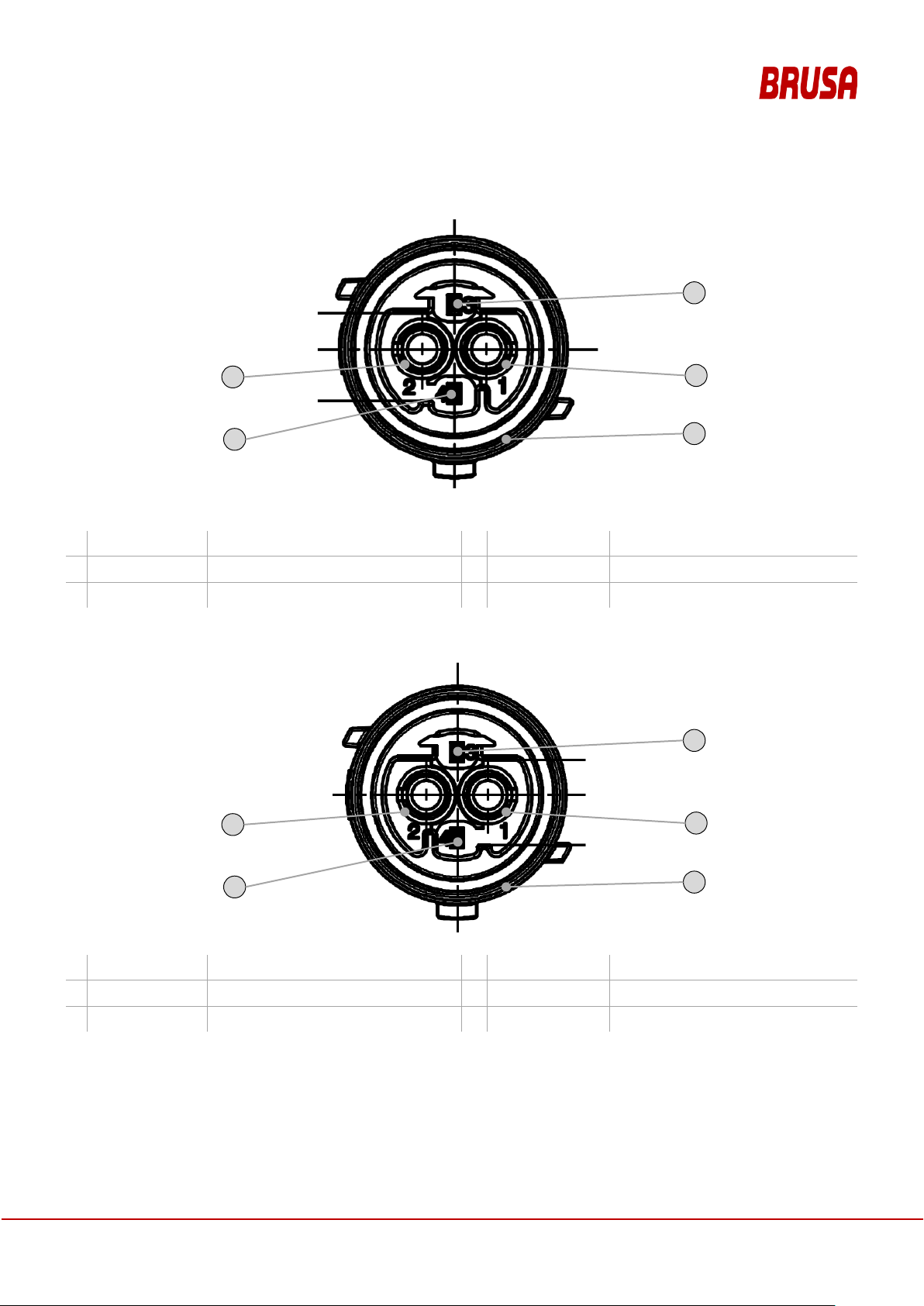
12.7.3.3 Pin Assignment HV-Connector (Code A)
1.
HV_DC_+
HV Battery Plus
2.
HV_DC_-
HV Battery Minus
3.
HVIL_in
HV-Interlock Loop Input
4.
HVIL_out
HV-Interlock Loop Output
5.
GND
Housing (equipotenti al bonding)
1.
HV_DC_+
HV Battery Plus
2.
HV_DC_-
HV Battery Minus
3.
HVIL_in
4.
HVIL_out
5.
GND
Housing (equipotenti al bonding)
1
2
3
4 5 1 2 3 4 5
12.7.3.4 Pin Assignment HV-Connector (Code B)
HV-Interlock Loop Input
HV-Interlock Loop Output
Operation Manual
Inductive Charging System
ICS115
59

Installation of the CPM requires a vehicle with insulation monitor
The CPM may only be installed in vehicles with an insulation monitor. In the CPM the HVDC live parts
are basic insulated against SELV (Safety Extra Low Voltage). As error
network of the
vehicle traction circuit is used. If the insulation monitor detects a failure of the insulation, a connection
of the HV
1
position of the
CPM
2
Determine that work step, for which the
battery, this must already be installed in the vehicle!
3
Ensure the availability of the CPM for the
integration of the CPM in the vehicle for
4
Ensure the availabilit y of th e connect ions in
Note the mechanical connection of the CPM in the vehicle as
5
Ensure the availability of the auxiliary
equipment and the information (user
manual), in order to be able to undertake
the installation of the CPM, and if
necessary, to be able to chec k the correct
n the planning,
CPM
6
assembly and installation of the CPM, is
available for the assembly and present
Caution during transport and storage of the CPM!
Note the technical specific ations of the CPM, e.g. weig ht. Please no te, that with c areless han dling of
12.7.4 Planning the Assembly and Installation of the CPM
CAUTION
-battery should be prevented.
WORK STEP ILLUSTRATION / OTHER INFO
Determine the installation
CPM.
CPM should be availab le fo r the insta llation
in the target vehicle.
that work step determined at 2.
the vehicle required for the CPM.
protection the IT-
Note the dimensions and i nstallation instruct ions of the
(user manual ICS) and the dimensions of the vehicle.
Please note, that for the connection of the CPM to the drive
Take into consideration the ordering- and delivery times.
well as connections to the vehicle battery and to the vehicle
wiring system.
Make sure to include corresponding tools i
-side and also vehicle-side.
installation.
Ensure, that all inform ation required f or the
Note the information- and communication channels.
during the assembly.
12.7.5 Transport and Storage of the CPM
CAUTION
the CPM, injuries are p os s ible: inj uri es on C PM or packaging, as well as injuries through allow in g th e
CPM to fall!
60
Inductive Charging System
Operation Manual
ICS115

WORK STEP ILLUSTRATION / OTHER INFO
1
Preparation: Determine, whether a
cautious and careful handling of the CPM
You
thereby avoid transport damage to the
Make sure, that routes for the manual transport are free (no
tripping hazards) and provide sufficient space!
2
Lifting: Lift the CPM taking into
consideration the weight, the dimensions
3
Handling and Transport: Mak e sure, that
Caution when placing t he CPM down o n smooth surfaces or
4
Setting down: Place the CPM (possibly in
Ensure compliance with the conditions in section 12.5.8 for
5
Storage: Store the CPM (possibly in
packaging) horizontal on a level surface.
Place the base area of t he CPM (possibly
in packaging) completely on the storage
Avoid damage to the CPM due to
Ensure compliance with the cond itions in sect ion 12.5.8.1 for
High Voltage!
damage before
and function control bef ore delivery.
(possibly in packaging) is possible.
CPM.
and the center of gravity.
you can safely hold the CPM while working.
packaging) on a level surface.
surface.
incorrect storage.
12.7.6 Installation of the CPM
if the CPM slips out of the packaging.
storage or transport of the CPM.
storage of the CPM.
DANGER
Danger to life!
Before commencing work, ensure zero voltage in the HV-circuit!
Follow the prescribed work sequence without fail!
Do not act recklessly and impetuously under any circumstances!
Visually inspect the packaging material and in particular the CPM itself for
installation. At BRUS A every CPM undergoes a strict qualityHowever we have no influe nce on the long trans port routes in som e cases and the loading ac tivities
of our products.
WORK STEP ILLUSTRATION / OTHER INFO
Operation Manual
Inductive Charging System
ICS115
INFORMATION
61

1
Separate the CPM from the rest of the
packaging material. Remove the film from
Remove the CPM caref ully from the packaging. Mak e sure not
to damage the CPM. Do not wear any jewelry during the
installation
2
the installation instructions of the
3
Install the CPM mechanically at the
intended location. For the installation use
the fastening points provided for this
Observe the installation i ns tr uctions (e.g. t orques f or s cr ews) of
the vehicle manufacturer for the installation of the CPM in the
intended vehicl
4
Establish the ground connection between
cable length should be chosen as short as possible.
5
Connect the HV-connector of the CPM with
the drive battery resp. the charging circuit
of the intended vehicle or with the air
ioning compressor of the intended
connector are to be
connected color matched (black and white). The HV-connector is
unambiguously connectable. If different possibilities exist for
plugging in, abort the in
6
Connect the LV-connec tor of the CPM with
connector is unambiguously connectable. If different
possibilities exist for plugging in, abort the
7
Switch the CPM power supply on.
If no connection can be established to the CPM, do not
continue with the f ollowing steps, rather f irst rectify the error in th e
communication.
8
Check the correct installation of the CPM.
9
Conclude the installation: Stow the tools
WORK STEP ILLUSTRATION / OTHER INFO
the heat conducting pad.
Follow
CPM for the target vehicle of the res pective
vehicle manufacturer.
.
purpose, see chapter 12.7.2.
CPM and vehicle.
condit
vehicle.
the wiring system of the target vehicle.
- Power supply
- Communication
e.
Note the position of the connection in chapter 12.7.3. The
The connections for the respective HV-
stallation at this point.
The LV-
installation at this point.
used and dispose of any other packaging.
After the 8th work step the CPM is installed ready.
12.7.7 Deinstallation of the CPM
The deinstallation of the CPM component may only be performed by specialist personnel. Contact customer
service.
62
Operation Manual
Inductive Charging System
ICS115

1
Ensure for a safe working environment
If the CPM is hot, wait until it has cooled
Make sure, that no sources of danger can occur during the
deinstallation (e.g. c rushing due to t he vehicle r olling a way). Do n ot
wear any jewelry during the deinstallation.
2
3
Follow the instructions for the removal of
the CPM for the intended vehicle of the
4
Dispose of the CPM, taking into
consideration the regulations for the
disposal of electrical devices in chapter
WORK STEP ILLUSTRATION / OTHER INFO
during the deinstallation.
down.
Interrupt the CPM Interlock.
respective vehicle manufacturer.
10.1.
Danger of injury with hot CPM.
Operation Manual
Inductive Charging System
ICS115
63

1
2014/53/EU
Provision of radio equipment on the market
2
2011/65/EU
Restriction of Hazardous Substances - RoHS
3
EN 55011:2009+A1:2010
Industrial, scientific and medical equipment - Radio-frequency disturbance
characteristics
4
EN 61000
:2014
Electromagnetic compatibility (EMC) – Par t 3-2: Limits - Limits for harmonic current
emissions
5
EN
2013
Electromagnetic compatibility (EMC) – Par t 3-3: Limits - Limitation of voltage
changes, voltage fluctuations and flicker
6
EN 61000-62:2005
Electromagnetic compatibility (EMC) – Par t 6-2: Generic standards - Immunity for
industrial environments
7
EN 300 328 V2.1.1
Wideband transmission systems - Data transmission equipment operating in the
2.4 GHz ISM band and using wide band modulation tech
8
EN 300 330 V2.1.1
Electromagnetic Compatibility and Radio Spectrum Matters (ERM) - Short Range
Devices (SRD)
9
EN 301 489-1 V2.1.1
Electromagnetic compatibility and Radio spectrum Matters (ERM); Electromagnetic
Compatibility (EMC) standard for radio equipment
10
EN 301 489-3 V2.1.1
Electromagnetic compatibility and Radio spectrum Matters (ERM); Electromagnetic
Compatibility (EMC)
11
EN 301 489
V3.2.0
Electromagnetic Compatibility (EMC) standard for radio equipment and services Part 17: Specific conditions for Broadband Data Transmission Systems
12
EN 50364:2010
Limitation of human exposure to electromagnetic fields from devices
13
EN 62479:2010
Assessment of the compliance of low power electronic and electrical equipment
with the basic restrictions related to human exposure to electromagnetic fields (10
MHz to 300 GHz)
13 Annex A2
13.1 Standards and Legal Requirements
The standards and legal requirements that the ICS product fulfills, are compiled in the following table:
Table 3: Standards
NO REQUIREMENT CONTENT
-3-2
61000-3-3:
+AC:2005
-17
- Limits and methods of measurement
niques
standard for radio equipment and services
64
Operation Manual
Inductive Charging System
ICS115

NO REQUIREMENT CONTENT
14
IEC 61980-1:2015
Electric vehicle wireless power transfer (WPT) systems - Part 1: General
requirements
15
ICNIRP 1998
Directives for the limitation of the exposure due to time-varying electric, magnetic
and electromagnetic fields (up to 300 GHz)
16
EN 50581:2012
Assessment of electrical and electronic products with respect to the restriction of
hazardous substances
13.2 DECLARATIONS OF CONFORMITY
13.2.1 SIMPLIFIED EU-DECLARATION OF CONFORMITY ICS115
BRUSA Elektronik AG herewith declares, that the radio equipment type ICS115 conforms to the directive 2014/53/EU.
The complete text of the EU-Declaration of Conformity is available at the following Internet address:
www.brusa.biz/<todo>
13.2.2 SIMPLIFIED EU-DECLARA TION OF CONFORMITY ICS1-WLAN-ATWILC-MU-D
BRUSA Elektronik AG herewith declares, that the radio equipment type ICS1-WLAN-ATWILC-MU-D conforms to the
directive 2014/53/EU. The complete text of the EU-Declaration of Conformity is available at the following Internet
address:
www.brusa.biz/<todo>
Operation Manual
Inductive Charging System
ICS115
65

14 Index
Abbreviations, 7
Alignment GPM, 43
Center of Gravity
CPM, 39
GPM, 38
Cleaning, 35
Cleanliness
CPM, 35
GPM, 35
Connections
CPM, 51
Contact
Customer Service, 10
Foreword, 8
Functionality, 13
Functionality
LOD, 22
Functionality
FOD, 22
Functionality
Efficiency Control, 23
Imprint, 2
Installation
CPM, 56
Installation and Commissioning
GPM, 26
Manufacturer, 10
Service, 10
Deinstallation, 36
CPM, 57
GPM, 49
Dimensions
CPM, 38
GPM, 37
Disposal, 36
Efficiency, 14
Emergency situations, 32
Energy Efficiency, 14
Installation information, 42, 50
Maintenance, 34
Mounting Rails GPM, 44
Position GPM, 43
Product identification
CPM, 10
GPM, 9
ICS, 9
Removal of the ICS, 36
Scope of Application
ICS, 12
Scope of supply, 11
66
Operation Manual
Inductive Charging System
ICS115

Storage
CPM, 55
GPM, 49
Support, 10
Technical Data
CPM, 41
Energy Supply, 14
GPM, 41
ICS, 40
Transport
CPM, 55
GPM, 49
Troubleshooting
by User, 33
Warranty, 36
Operation Manual
Inductive Charging System
ICS115
67

15 Glossary
Derating
Reduction of the charging capacity. Protective function of the system when limits are exceeded, e.g.
temperature limits.
Electromagnetic Field
Physical effect, during which electrically conductive objects situated within the field heat up and therefore
can cause dangers for people (e.g. burning, fire).
Electromagnetic Induction
Physical effect, on which the cordless transmission of energy from the charging station (GPM) to the
vehicle (CPM) is based
Operation Manual
Inductive Charging System
68
ICS115
 Loading...