

Page 1
BRUSA Elektronik AG
Neudorf 14
CH-9466 Sennwald
+41 81 758 19 00
[email protected]
www.brusa.biz
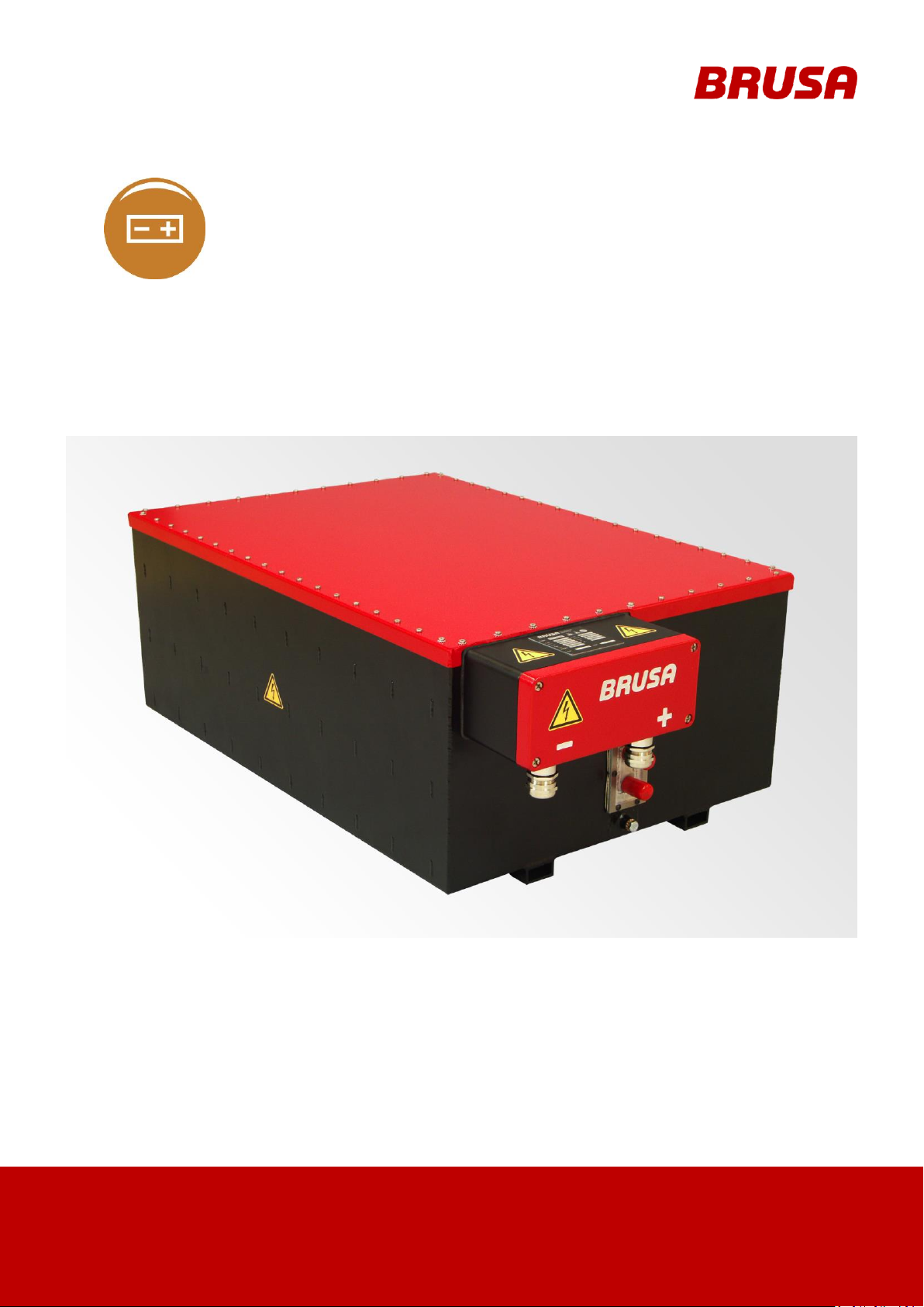
EVB1-400-40-HP
EVB1-350-40-HP
TECHNICAL DATA
AND START-UP
Translation of the original German operating instructions
Page 2
Technical data
and start-up
EVB1-350/400-40-HP
2
LEGAL NOTICE
Publisher
BRUSA Elektronik AG
Date of issue
13 Juni 2013
Copyright
© 2013
The content of this document may not be passed on to third parties without the written authorisation
of the company BRUSA Elektronik AG - not even in extracts. Any technical information, drawings
and photos used are copyrighted and failure to respect this constitutes a punishable offence!
Updates
In light of the further technical development of our products, we reserve the right for structural
changes. Any changes will be disclosed in the relevant manuals through the replacement of the
relevant pages and/or a revision of the electronic data storage device.
Writer / Author
Holger Schmidt
REVISION
DATE
NAME
CHANGE
01
24.10.2014
R. Roth
Preparation of Document based on standard Battery
Manual
chap. 4.3.1 adjust diagram to HP
chap. 4.3.2 adjust diagram to HP
chap. 6.4 adjust diagram to HP
chap. 6.5 adjust diagram to HP
chap. 6.6.3 adjust diagram to HP
chap. 3.4.1 adjust diagram to HP
chap. 3.3.3 add a comment about responsibility
02
28.05.2015
R. Roth
chap. 3.4.1 adjust diagram
03
29.12.2015
R. Roth
chap. 3.4.1 adjust and add diagram
chap. 3.4.2 adjust diagram
chap. 6.6.2 adjust diagram
REVISIONS
Page 3
3
Technical data
and start-up
EVB1-350/400-40-HP
VALIDITY
EVB1-400-40-A02-HP
EVB1-350-40-A03-HP
This manual is valid only for the following devices:
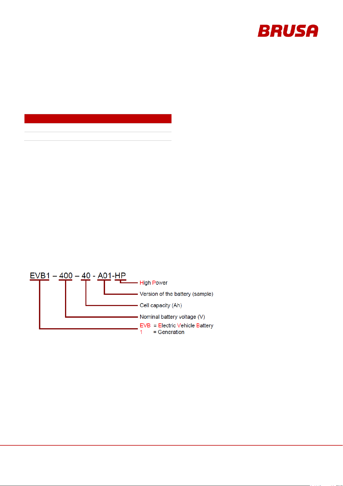
Decoding of the device designation is as follows:
Page 4

Technical data
and start-up
EVB1-350/400-40-HP
4
TABLE OF CONTENTS
1 Foreword .............................................................................................................................. 8
2 List of abbreviations ........................................................................................................... 8
3 Safety and Warning Instructions........................................................................................ 9
3.1 Symbols and their meaning ........................................................................................................ 9
3.2 Safety instructions and danger levels ....................................................................................... 10
3.3 Generally applicable safety measures ...................................................................................... 11
3.3.1 Safety instructions for cooling water systems .................................................................... 11
3.3.2 Safety instructions for handling and operation ................................................................... 11
3.3.3 Instructions for Storage and Transportation ....................................................................... 13
3.3.4 Safety instructions for electrical systems ........................................................................... 14
3.4 Safety installations / power limitations ...................................................................................... 15
3.4.1 Temperature Monitoring (Derating) ................................................................................... 15
3.4.2 Current Monitoring (Derating) ............................................................................................ 17
3.4.3 Monitoring of Cell Voltages ................................................................................................ 19
3.4.4 Main Fuse of the Battery ................................................................................................... 20
3.4.5 Contactors in the BMS ...................................................................................................... 21
3.4.6 Emergency Stop Switch .................................................................................................... 21
3.5 Requirements of the Start-up Personnel ................................................................................... 21
4 General ............................................................................................................................... 22
4.1 Content and Scope of this Manual ............................................................................................ 22
4.2 Scope of the Entire Documentation .......................................................................................... 22
4.3 Delivery Contents ..................................................................................................................... 23
4.4 Optional Delivery Contents ....................................................................................................... 24
4.5 EU Guidelines .......................................................................................................................... 24
4.6 Contact Information of the Manufacturer .................................................................................. 24
5 Use and Limits of the Product ................................................................ .......................... 25
5.1 Proper Use ............................................................................................................................... 25
5.2 Improper Use ........................................................................................................................... 26
6 About This Device ............................................................................................................. 27
6.1 Technical Data ......................................................................................................................... 27
6.2 Technical Properties ................................................................................................................. 28
Page 5

5
Technical data
and start-up
EVB1-350/400-40-HP
6.3 Warning Instructions on the Battery .......................................................................................... 29
6.4 Basic Principle for Vehicle Installation ...................................................................................... 30
6.5 Safety measures for vehicle installation .................................................................................... 31
6.5.1 Principle of operation Interlock .......................................................................................... 31
6.6 Basic Function Batterie EVB1-400/350-40-HP ......................................................................... 32
6.6.1 EVB1-400/350-40-HP Block Circuit Diagram ..................................................................... 33
6.6.2 Pre-charging Voltage ......................................................................................................... 34
6.6.3 Temperature Measurement / Temperature Monitoring ...................................................... 35
6.6.4 Balancing .......................................................................................................................... 36
6.6.5 Auto-reset of the Ah Meter ................................................................................................ 37
6.7 Overview of the Main Structural Components ........................................................................... 38
6.8 Dimensions and Installation Information ................................................................................... 39
6.8.1 Fixing Points...................................................................................................................... 39
6.8.2 Dimensions ....................................................................................................................... 40
6.8.3 Installation Position ........................................................................................................... 40
6.9 Regulation and Control System ................................................................................................ 41
6.9.1 Control via Terminal 15 (without CAN Bus) ....................................................................... 41
6.9.2 Control via Terminal 15 with Driving via CAN .................................................................... 42
7 Connections ....................................................................................................................... 43
7.1 Circuit Connections .................................................................................................................. 43
7.2 Ground (GND) .......................................................................................................................... 44
7.3 Pin Assignment of Control Plug (Device-side) ................................ .......................................... 45
7.3.1 Pin 1 GND ......................................................................................................................... 46
7.3.2 Pin 2 AUX ......................................................................................................................... 46
7.3.3 Pin 3 EN ............................................................................................................................ 47
7.3.4 Pin 4 PWML / PWM-out .................................................................................................... 47
7.3.5 Pin 5 PWMP / PWM-out .................................................................................................... 48
7.3.6 Pin 9 CAN1L, Pin 10 CAN1H ............................................................................................ 48
7.3.7 Pin 8 APG, Pin 14 CANG, Pin 15 RS232G ........................................................................ 49
7.3.8 Pin 11 RS232T, Pin 12 RS232R........................................................................................ 49
7.3.9 Pin 13 PRO ....................................................................................................................... 50
7.3.10 Pin 16 RFK1, Pin 17 RFK2, Pin 18 RFKC ......................................................................... 51
7.3.11 Pin 19 INT1, Pin 20 INT2................................................................................................... 52
Page 6

Technical data
and start-up
EVB1-350/400-40-HP
6
7.3.12 Pin 21 NAUS ..................................................................................................................... 53
8 Profiles and Diagrams ....................................................................................................... 54
8.1 Charging / Discharging of Battery ................................................................ ............................. 54
8.1.1 Charging (120 A) EVB1-400-40-HP ................................................................................... 54
8.1.2 Discharging (80A) EVB1-400-40-HP ................................................................................. 54
8.1.3 Discharging (320 A peak) EVB1-400-40-HP ...................................................................... 55
8.1.4 Discharging (600 A peak) EVB1-400-40-HP ...................................................................... 55
8.1.5 Charging (120 A) EVB1-350-40-HP ................................................................................... 56
8.2 Discharging (200 A) EVB1-350-40-HP ..................................................................................... 56
8.2.1 Discharging (80 A) EVB1-350-40-HP ................................................................................ 56
8.2.2 Discharging (320 A peak) EVB1-350-40-HP ...................................................................... 57
8.2.3 Discharging (600 A peak) EVB1-350-40-HP ...................................................................... 57
8.3 Temperature / Cooling System ................................................................................................. 58
8.3.1 Cooling Behaviour at Cooling Water Inlet Temperature +5°C ............................................ 58
8.3.2 Cooling Behaviour at Cooling Water Inlet Temperature +15°C .......................................... 58
8.3.3 Cooling Behaviour at Cooling Water Inlet Temperature +25°C .......................................... 59
8.3.4 Cooling Behaviour without Active Cooling (Cooling Circuit Deactivated) ........................... 59
9 Installation / Initial Start-up .............................................................................................. 60
9.1 Unpacking the Battery .............................................................................................................. 67
9.2 Building HV Supply ................................................................................................................... 69
9.3 Ventilating the Cooling System ................................................................................................. 72
9.4 Installing the CAN Dongle ........................................................................................................ 72
10 Operation ........................................................................................................................ 73
10.1 Reading CAN Parameters ........................................................................................................ 73
10.1.1 Debug Messages – Data Logging with PARAM ................................................................. 73
10.1.2 Analysing Battery Data ...................................................................................................... 74
10.2 Live View of the Battery Data ................................................................................................... 75
10.3 Changing the CAN Parameters with PARAM ........................................................................... 76
10.3.1 Configurable Parameters................................................................................................... 80
10.4 Charging with the NLG513 Charger ......................................................................................... 82
10.4.1 Charging via the CAN ........................................................................................................ 82
10.4.2 Course of a Charging Process .......................................................................................... 83
10.5 Charging with the NLG664 Charger ......................................................................................... 84
Page 7

7
Technical data
and start-up
EVB1-350/400-40-HP
10.6 Carrying Out Firmware Updates ............................................................................................... 85
11 CAN Matrix ...................................................................................................................... 89
11.1 CAN Signals / Messages .......................................................................................................... 89
11.2 CAN Signals / Errorand Warning Messages ............................................................................. 91
12 Warranty .......................................................................................................................... 96
13 Instructions for Disposal ............................................................................................... 96
14 Index ................................ ................................ ................................ ................................ 97
Page 8

Technical data
and start-up
EVB1-350/400-40-HP
8
ABBR.
MEANING
ABBR.
NAME
BMS
Battery Management System
Li-Ion
Lithium Ionen Battery
CAN
Controller Area Network
MDF
Measurement Data Format
CCU
Cell Contol Unit
Ni-Cd
Nickel-Cadmium Battery
DoD
Depth of Discharge (Discharging state)
Ni-MH
Nickel-Metal Hydride Battery
EVB
Electric Vehicle Battery
PTC
Positive Temperature Coefficient
(Thermistor)
HV
High Voltage
PDU
Power Distribution Unit (HV Distributor)
IP
Ingress Protection
SoC
State of Charge
1 Foreword
Dear customer!
With the BRUSA Batterie EVB1-400/350-40 you have obtained a very capable and versatile product. As this is a
high performance electronic product, specialist knowledge is required for dealing with it as well as operating it!
Read this manual - particularly the chapter Safety and Warning Instructions - carefully before you install the battery
or carry out any other work on it!
2 List of abbreviations
Throughout this manual, some specific technical abbreviations are used. You will find an overview as well as their
meaning in the following table:
Page 9
9
Technical data
and start-up
EVB1-350/400-40-HP
3 Safety and Warning Instructions
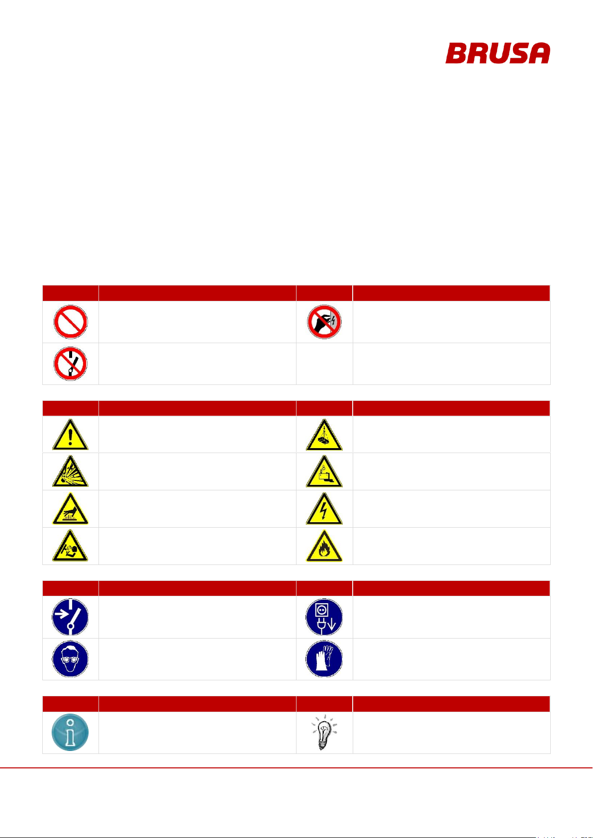
PROHIBITION SYMBOLS
SYMBOL
MEANING
SYMBOL
MEANING
General prohibition
Warning high voltage
Touching forbidden
Switching on forbidden
WARNING SYMBOLS
SYMBOL
MEANING
SYMBOL
MEANING
General hazard warning
Suspended load hazard warning
Potentially explosive warning
Battery hazard warning
Hot surface warning
High electrical voltage warning
High pressure warning / fluid spurting out
Fire hazard warning
MANDATORY SIGNS
SYMBOL
MEANING
SYMBOL
MEANING
Disconnect device from voltage
Disconnect device from mains
Wear protective glasses
Wear protective gloves
INFORMATION SIGNS
SYMBOL
MEANING
SYMBOL
MEANING
Important information on avoiding possible
damage to property
Important information
In this chapter you will find safety instructions which apply to this device. These refer to assembly, start-up and
running operation in the vehicle. Always read and observe these instructions in order to protect people's safety and
lives and to avoid damage to the device!
3.1 Symbols and their meaning
Throughout this manual, some specific technical abbreviations are used. You will find an overview as well as their
meaning in the following table:
Page 10
Technical data
and start-up
EVB1-350/400-40-HP
10
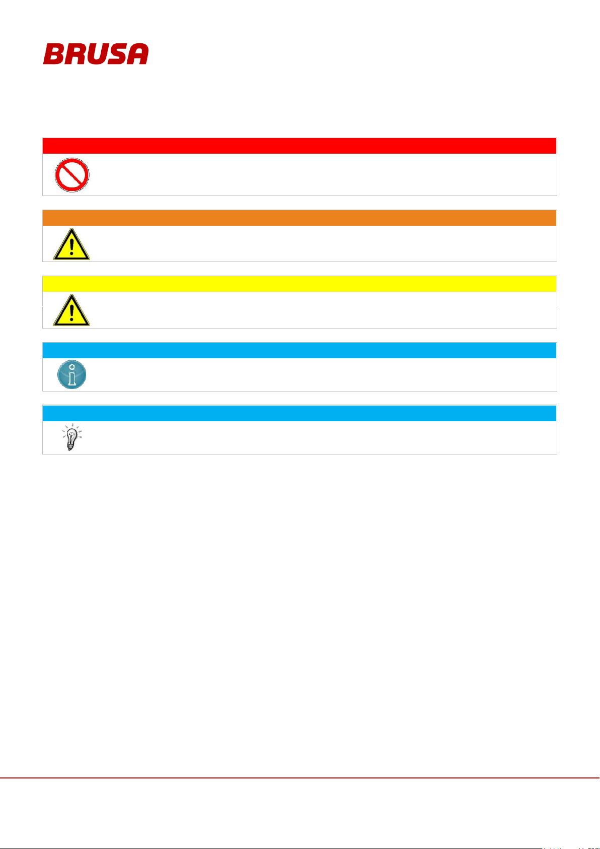
DANGER
This instruction warns against serious, irreversible risks of injury and in some cases death!
Avoid these dangers by observing these instructions!
WARNING
This instruction warns against serious, irreversible risks of injury!
Avoid these dangers by observing these instructions!
CAUTION
This instruction warns against serious, irreversible risks of injury!
Avoid these dangers by observing these instructions!
INSTRUCTION
This instruction warns against possible damages to property if the following instructions and work
procedures are not observed.
INFORMATION
This type of instruction discloses important information for the reader.
3.2 Safety instructions and danger levels
Page 11
11
Technical data
and start-up
EVB1-350/400-40-HP
3.3 Generally applicable safety measures
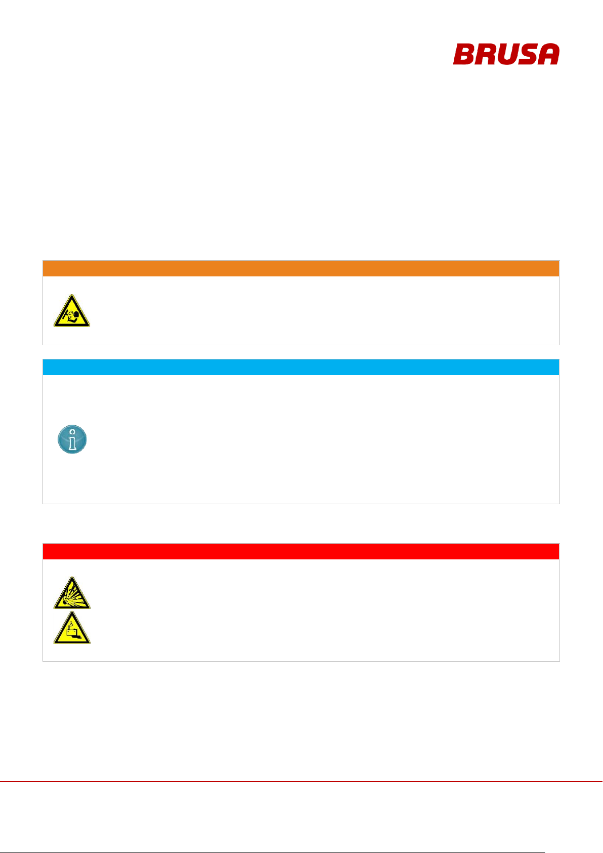
WARNING
Spurting cooling fluid!
Skin burning hazard!
Check the tightness of the cooling water system, particularly the pipes, screw joints and pressure
tanks.
Resolve recognisable leakages immediately!
INSTRUCTION
The cooling water must always be actively cooled to ensure the optimum operating temperature.
To achieve the optimum performance, the temperature at the cooling water inlet should not
exceed +20°C. At temperatures higher than this, the cooling water to battery Delta-T does not
reach high enough a level to have a cooling effect!
Furthermore, we recommend the use of a climate compressor for the active cooling of the
battery. At ambient temperatures of > 30°C, the maximum temperature of the battery (+45°C)
can be reached very quickly through operation and recuperation or charging. When the
maximum temperature is reached, charging and/or recuperation is no longer possible!
Even when the optimum operating temperature is deceeded, the capacity of the battery
diminishes continually.
DANGER
Explosion Danger!
Danger to life!
Under no circumstances should you carry out unauthorised work on the battery! This can lead to
the deactivation of security installations and can then lead to fire or an explosion!
Under no circumstances should you link the positive and negative poles with a metal object!
Never heat or burn a cell packet! This leads to the release of toxic fumes and to explosions!
The installation of the battery must take place in an EMI secure environment!
The following safety measures have been developed based on the knowledge of the manufacturer. They are not
complete, they can be supplemented by local and/or country-specific safety instructions and guidelines for accident
prevention!
The system integrator and/or distributor of the device must therefore supplement the present general safety
instructions by country-specific and local guidelines.
3.3.1 Safety instructions for cooling water systems
3.3.2 Safety instructions for handling and operation
Page 12
Technical data
and start-up
EVB1-350/400-40-HP
12
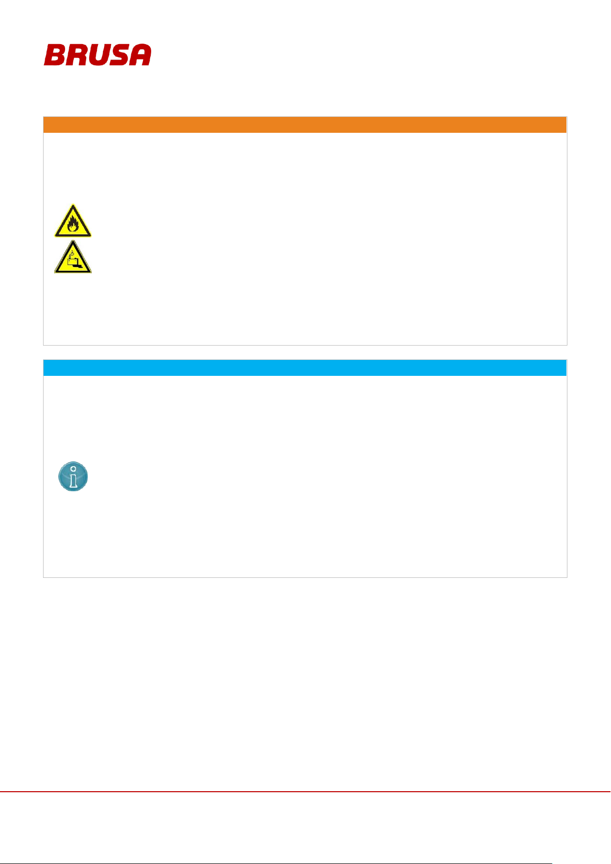
WARNING
Overheating!
Fire hazard!
Always end the charging process after the given charging time is up even if the battery has not
charged to 100%! A significant extension of the charging time can lead to overheating and then
to the setting alight of the battery!
Do not use the battery or even the single cell packets for other purposes! This can lead to the
emission of smoke and to fire!
In the case of a defective battery or defective cell packets harmful fumes can occur! So, in
general, make sure that both the charging process as well as any other work on the battery are
carried out in a secure environment with sufficient fresh air supply!
In the case of any recognisable mechanical damage to the battery housing, odour coming from it
or the emission of smoke you must stop operating the battery immediately! In this case, the
battery must not be used again until it has undergone a professional inspection by the
manufacturer!
Always avoid anything which will have serious mechanical implications for the battery! This can
lead to the cell structures being destroyed and this can then lead to short-circuiting or fire!
INSTRUCTION
A high cooling water temperature reduces the life span! So take ongoing care to ensure sufficient
cooling of the device!
Even if the battery has high IP protection, direct contact with water (rain, splashing water) should
be avoided as far as possible while in operation!
Under no circumstances should you put a low-resistance connection between the HV contacts,
the housing contacts and the LV contacts! This will lead to malfunctions and then to the
destruction of the battery!
Before connecting the wiring, ensure that the battery poles are correctly connected! Reverse
polarity can lead to the destruction of both the battery and other devices!
During any charging outside of the vehicle, ensure that the battery is on an even, non-conductive
surface!
Never charge the cell packets at a voltage higher than 4.2 V and never discharge them at a
voltage lower than 2.7 V per cell! This can lead to damage to the cell packets!
Do not connect the battery to other batteries e.g. dry batteries, Ni-Cd or Ni-MH batteries! These
could have different capacities or voltages and lead to faults in the system!
Page 13
13
Technical data
and start-up
EVB1-350/400-40-HP
3.3.3 Instructions for Storage and Transportation
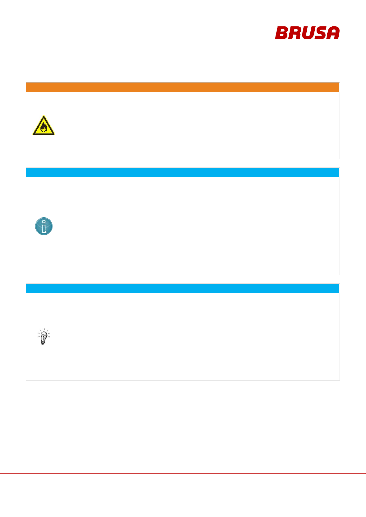
WARNING
Overheating!
Fire hazard!
Avoid storing or operating the device in close proximity to heat sources or direct sunlight! This
will lead to the overheating of the battery and can lead to the cell packets going on fire!
Never store or transport the battery in direct contact with metal objects! This can lead to short-
circuits and then to fire!
Do not store any highly flammable materials or combustible fluids in the direct surroundings of
the device! Sparks at the device connections can set these on fire and lead to explosions!
INSTRUCTION
When storing the battery, the specified ambient temperature must always be adhered to. Storage
outside these temperatures can lead to damage to the cell packets! So the battery must be
stored in a secure environment which is inaccessible to children under the following conditions:
Ambient temperature during a storage time of < 365 days = -20°C to +25°C
Ambient temperature during a storage time of < 90 days = -20°C to +40°C
In general the cell voltage should not fall below 2.6 V. If this is the case, the battery cannot be
switched on again! In this case, a return to service can be carried out only by BRUSA experts!
In general make sure that the SoC level is at around 50% before prolonged shut-down or storage
of the battery! In the case of a complete discharge of the battery, we recommend switching off
the battery and recharging it as soon as possible so that the threshold of < 2.6 V is never fallen
short of!
INFORMATION
The battery is a dangerous good and is therefore subject to special, country-specific packaging
and labelling guidelines! Before sending the battery anywhere, find out about the necessary
transport measures from local logistics services. For instructions on the transporting of the
battery, note the reverse order of chapter 9.1.
The battery may only be sent in the transport box it was delivered in or alternatively in an
equivalent transport box. Should you have any questions, refer to the company BRUSA
Elektronik AG at the manufacturer address given in chapter 4.6.
For safety reasons, the battery should be charged to around 50% (SoC) for transportation. Pay
attention to the charge level during the first installation and in doing so, adhere to the power data
and parameters of your charging device.
For transports after the delivery, BRUSA Elektronik AG assume no responsibility
Page 14
Technical data
and start-up
EVB1-350/400-40-HP
14
DANGER
High voltage!
Danger to life!
Under no circumstances should you touch the HV wires and connections without ensuring that
there is no voltage beforehand!
The battery may only be connected by a qualified electrician!
Under no circumstances should you bypass or avoid security installations! Any malfunctions
resulting from this could have life threatening consequences!
Before starting work with the battery, the shut-down of the coupled motor must be ensured! Even
when the HV supply is switched off, a turning motor can still produce voltage!
INFORMATION
Adhere strictly to the following 5 safety rules when working on a HV grid:
Disconnect system from power.
Switch off the ignition.
Remove service / maintenance plug and/or turn off main battery switch.
Remove the fuse (external fuse box).
Ensure that system does not reconnect.
Keep ignition key safe to prevent unauthorised access.
Keep service / maintenance plug safe to prevent unauthorised access and/or
use lockable protective cap to ensure that the main battery switch does not reconnect.
Check that it is not live with a suitable voltage tester (note voltage range!).
Ground and short-circuit the system.
Cover or seal off adjacent live parts.
3.3.4 Safety instructions for electrical systems
Page 15
15
Technical data
and start-up
EVB1-350/400-40-HP
3.4 Safety installations / power limitations
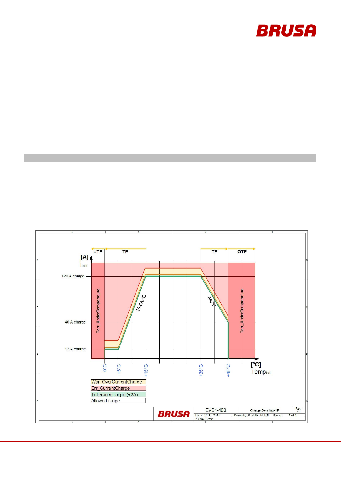
Charging
If the battery temperature is lower than 15°C, the derating begins till 5°C (reducing current with 10.8A/°C).
If the battery temperature is lower than 5°C, the BMS allows a maximum charging current of 12A till 0°C
Below 0°C the BMS limit the charging current to 0A
To inform you the CAN signal BMS_MODE_TP is emitted.
If the battery temperature is above 35°C, the derating begins till 45°C (reducing current with 8A/°C).
To inform you the CAN signal BMS_MODE_TP is emitted.
Above 45°C the BMS stops the charging process
3.4.1 Temperature Monitoring (Derating)
This security installation is the battery's self-protection. If a cell packet achieves a defined temperature threshold,
this means a decrease in power (derating) to protect the battery from damage through overheating. The power will
subsequently be reduced until the temperature falls back to the target range. If a cell reaches the defined limit, the
current is reduced to 0 A. If the temperature rises despite derating and the defined default values of the battery are
not adhered to, the battery is immediately disconnected from the DC intermediate circuit. Further information on
temperature measurement can be found in chapter 6.6.3 Temperature Measurement / Temperature Monitoring
Page 16
Technical data
and start-up
EVB1-350/400-40-HP
16
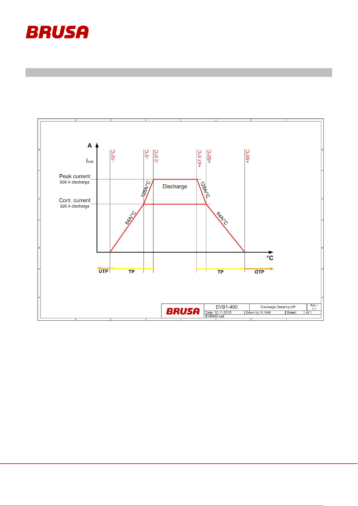
Discharging
2.5°C before the actual derating, pre-derating begins and reducing the current from 600 A to 320 A
(BATT_CurrentDischargeMax) at a rate of 128 A / °C.
To inform you the CAN signal BMS_MODE_TP is emitted.
5°C before reaching the limit of temperature, the actual derating engages at a rate of 64A/°C reducing the
current to 0 A (BATT_CurrentDischargeMax).
Page 17
17
Technical data
and start-up
EVB1-350/400-40-HP
3.4.2 Current Monitoring (Derating)
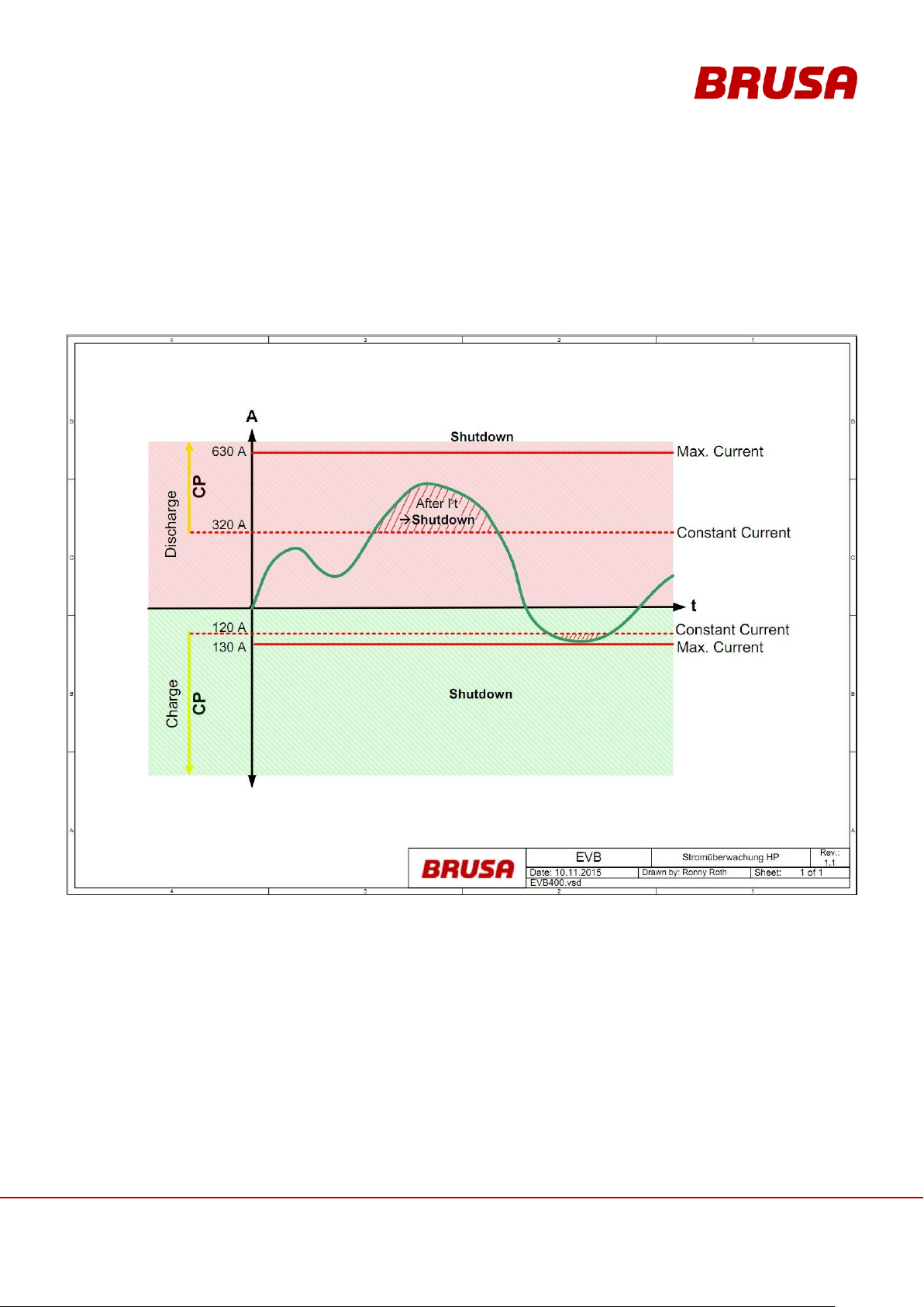
In the BMS the current is continually measured at 2.5 s intervals. This measurement can be communicated via
CAN (BATT_Current_Act). Alongside this, a second measurement is taken continually at 125 ms intervals, this has
a poorer resolution due to the shorter measurement time (6 A). This parallel measurement makes a very fast
reaction / shut-down possible in the case of an overload. With this, the BMS can recognise a short-circuit within just
6 ms and disconnect the battery from the DC intermediate circuit.
Page 18

Technical data
and start-up
EVB1-350/400-40-HP
18
Step 1: Warning and Limit Reached
As soon as the limit is reached or exceeded, the warning message or CAN signal
MS_War_OverCurrentCharge or BMS_War_OverCurrentDischarge is emitted.
In addition, the CAN signal BMS_MODE_CP is emitted.
Step 2: Limit Reached, Peak Current Duration Exceeded
The maximum discharging current (600 A) can run for a duration of around 10 s. This produces a current field
output (I2t) of 784’000 A2s.
(I
peak
– I
cont
)2 * t = I2t
(600A – 320A)2 * 10s = 784‘000A2s
If this value is reached, the derating mode enters immediately and reduces the discharge current gradually
down to <320 A (discharge cont.).
With a discharge current <320 A, the battery can recover. The longer the recovery period, the longer it can
then be run again with the maximum discharge current (max. 10 s).
It is recommended that the derating of the current be followed (BATT_CurrentDischargeMax).
If the current field output is reached or exceeded (I2t), the battery automatically disconnects from the DC
intermediate circuit and sends an error report or the CAN signal BMS_TErr_DischargeI2t.
Step 3: Maximum Current Exceeded
If the current exceeds a level of 630 A or falls below -130 A, the battery is immediately disconnected from the
DC intermediate circuit.
The CAN signal BMS_Err_CurrentCharge / BMS_Err_CurrentDischarge is emitted.
The current monitoring takes place in three steps:
Page 19
19
Technical data
and start-up
EVB1-350/400-40-HP
3.4.3 Monitoring of Cell Voltages
In the BMS the two highest and the two lowest cell voltages are measured at intervals of 1 ms. These are relayed
with the CAN signal CCU_V. Additionally every cell is measured in series at a frequency of around 1 kHz. The
values measured are identified with an index and relayed one after another via CAN CCU_Cell. The following
factors are included in this index:
Number of cells (CCU_Number)
Current index (CCU_Index)
Associated voltage (CCU_V)
Associated Temperature (CCU_T)
The maximum and minimum voltage are averaged over a time frame of 100 ms and are relayed with the CAN
signal CCU_max (CCU_V_LOW_PEAK / CCU_V_HIGH_PEAK). For each voltage measurement, an internal
resistance of 1 mohm per cell is factored in.
Page 20
Technical data
and start-up
EVB1-350/400-40-HP
20
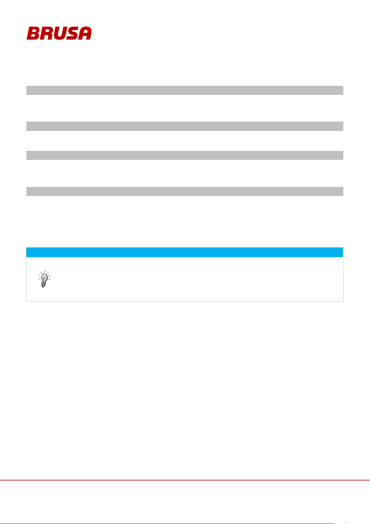
Step 1: Warning
As soon as the cell voltage is larger than 4.10 V, the warning message or the CAN signal
BMS_War_OverCharge is emitted.
This CAN signal indicates that the maximum cell voltage will soon be reached.
Step 2: Limit Reached
If the cell voltage surpasses 4.15 V, the CAN signal BMS_MODE_OVP is emitted.
This CAN signal means that the maximum cell voltage has been reached.
Step 3: Limit Reached and Further Charging of the Cells
If another 0.5 Ah is charged after the CAN signal BMS_MODE_OVP is emitted, the battery immediately
disconnects from the DC intermediate circuit.
The error message or the CAN signal BMS_Err_OverCharge is emitted.
Step 4: Max. Cell Voltage Exceeded
If the cell voltage reaches 4.20 V, the battery will always be disconnected from the DC intermediate circuit
immediately.
The error message or the CAN signal BMS_Err_OverCharge is emitted.
If this is the case, then a general error exists in the battery. A diagnosis must be carried out by qualified
specialist personnel.
INFORMATION
The monitoring of under-voltage takes place in the four specified stages with the following CAN
signals:
BMS_War_OverDischarge
BMS_MODE_UVP
BMS_Err_OverDischarge
Monitoring of the cell voltages takes place in four steps:
3.4.4 Main Fuse of the Battery
The battery has a 600 A DC semiconductor fuse. The main fuse protects the cell packets. The battery cables must
be secured separately over a PDU. As a rule the main fuse will only be tripped through a serious defect or shortcircuit in the battery. If this is the case, the battery must be sent back to be repaired! The replacement of the main
fuse may only be carried out by the company BRUSA Elektronik AG because specialist knowledge is necessary for
this!
Page 21

21
Technical data
and start-up
EVB1-350/400-40-HP
3.4.5 Contactors in the BMS
The contactors in the BMS (HV+ and HV-) can be controlled by the customer, e.g. via terminal 15. The contactors
disconnect the power supply to the HV cables. This prevents unwanted current flows. This way the vehicle is in a
secure state. To energise the contactors a peak inrush current of 3.7 A per contactor is required.
The contactors are generally automatically closed in the following states:
BMS_Active
BMS_NLG_Charger
In all other states, the contactors are open. The BMS_Precharge state is an exception. In this state the contactors
are closed in coordination. See chapter 6.9 Regulation and Control System.
3.4.6 Emergency Stop Switch
The emergency stop switch must be engaged by the customer. We recommend installation in the passenger
compartment area. The operator (driver) must be able to reach the emergency stop button in any situation. The
emergency stop switch must be installed in such a way that it influences the BMS power contactors directly. The
emergency stop switch must be designed for a continuous current of 1 A and a peak current of 10 A. The
emergency stop switch performs as an opener (on activation the breaking of the circuit takes place).
3.5 Requirements of the Start-up Personnel
All courses of action described in this manual may only be carried out by a qualified electrician! Specialist staff are
defined as electricians who dispose of
professional training,
knowledge and experience in the field of high voltage electronics / electric mobility,
as well as knowledge of relevant requirements and dangers
which they can display in practice. Furthermore, they must be able to assess the work assigned to them
independently, detect possible dangers and establish necessary protection measures.
Page 22
Technical data
and start-up
EVB1-350/400-40-HP
22
INFORMATION
To start up the battery successfully, you will need the entire documentation as well as various types
of software. With the provision of the customer package, it is ensured that they are complete and upto-date. The updating of specific documents is carried out automatically and can be seen in the
history.
4 General
4.1 Content and Scope of this Manual
The present documentation gives the reader an overview of all required operating steps for the installation and the
operation along with the safety measures necessary for these.
Furthermore, you can find the specifications, usage information and a basic description of the battery and its
specific components.
The operation and safety instructions given must be strictly adhered to ensure the ongoing optimum functioning of
the battery and to meet the guarantee requirements of the company BRUSA Elektronik AG.
4.2 Scope of the Entire Documentation
The customer package includes the following indexes:
Manual:
Contains all information fundamentally necessary for the installation and operation of the battery.
Tools:
Contains additional tools for the operation, parameter setting and maintenance of the battery.
History:
Listing of all upgrades within the customer package with a specification of the affected documents or
software / firmware etc.
Page 23
23
Technical data
and start-up
EVB1-350/400-40-HP
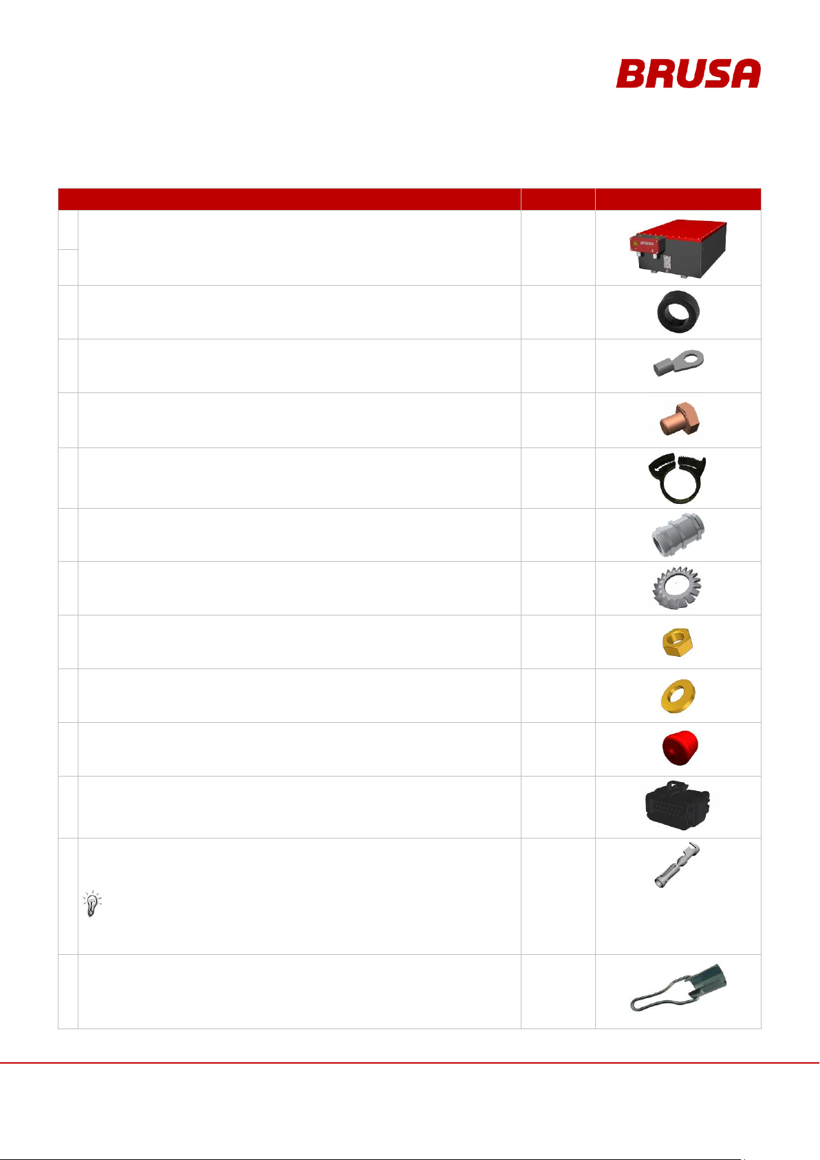
4.3 Delivery Contents
NAME
PIECES
ILLUSTRATION
1.
EVB1-400-40-HP battery including BMS
or
1
2.
EVB1-350-40-HP battery including BMS
3.
Magnetic core for EMI screening of the battery.
2
4.
M8 cable lug without insulation respectively for:
cable diameters of 50 mm2 and 35 mm2
4
5.
M8 x 10 hexagon screw
(GND)
(pre-assembled)
1
6.
Hose clips
3
7.
Cable gland 9-16 mm with extension
(pre-assembled)
2
8.
Serrated lock washer M8 for M8 x 10 screw
(pre-assembled)
1
9.
M8 hexagonal nut
(pre-assembled)
2
10.
M8 washer without chamfer DIN125
(pre-assembled)
2
11.
Protective cap for cooling water connection pieces
(pre-assembled)
2
12.
23-pole control plug for crimp terminals
AMPSEAL 770680-1
1
13.
SN/LP crimp terminal
AMPSEAL 770854-1
for wire diameter: 0.5 mm
2
We recommend the use of the following crimping tool:
Tyco 58440-1
23
14.
Special key for HV cable fitting
1
Page 24
Technical data
and start-up
EVB1-350/400-40-HP
24
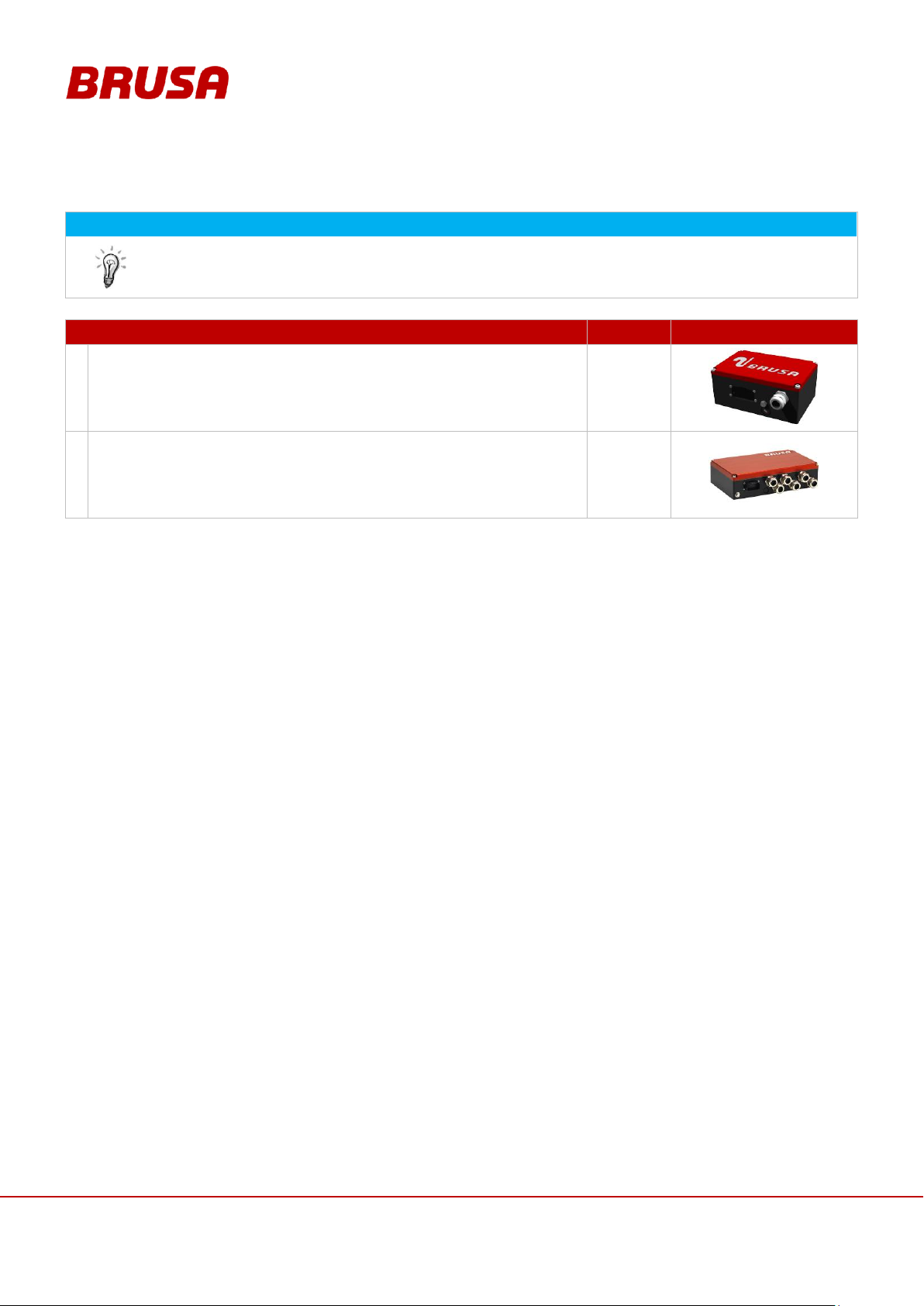
INFORMATION
These accessories can be included optionally.
The battery does not have an integrated insulation monitoring unit! This can be obtained from
BRUSA optionally.
NAME
TYPE
ILLUSTRATION
1.
Insulation monitoring unit
200214
2.
Power distribution unit PDU254
00147
BRUSA Elektronik AG
Neudorf 14
9466 Sennwald
Switzerland
Phone:
+41 81 758 19 - 00
Fax:
+41 81 758 19 - 99
Internet:
www.brusa.biz
E-mail:
4.4 Optional Delivery Contents
4.5 EU Guidelines
This manual has been produced under application and consideration of the EC guidelines, national laws and
harmonised standards (EN) valid at the time of production relevant to the product Batterie EVB1-400/350-40-HP.
4.6 Contact Information of the Manufacturer
Page 25
25
Technical data
and start-up
EVB1-350/400-40-HP
5 Use and Limits of the Product
INFORMATION
This equipment is a custom built evaluation kit destined for professionals to be used solely at
research and development facilities for such purposes.
5.1 Proper Use
The product Batterie EVB1-400/350-40-HP is designed for the following uses - bearing in mind the limits given in
chapter 5.2 :
Installation in a drive train for hybrid vehicles
Installation in a drive train for electric vehicles
Installation in a drive train for fuel cell vehicles
Use in high-performance driving (motor-racing sector)
Installation in a drive train for electric motorbikes
Installation in a drive train for utility vehicles (electric and hybrid)
Installation in a drive train for electric motorboats
Test stand applications
For planned uses in areas outside of those previously defined, the buyer undertakes to agree on these with the
manufacturer and to obtain written clearance for this.
Page 26
Technical data
and start-up
EVB1-350/400-40-HP
26
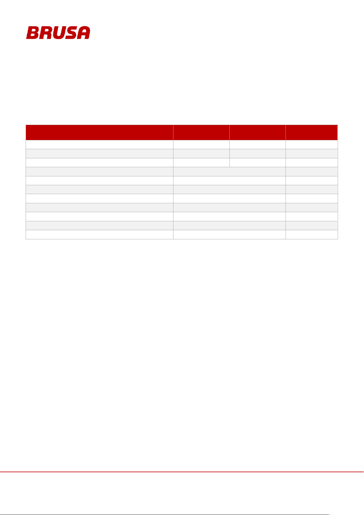
EVB1-350-40-HP
EVB1-400-40-HP
UNIT
Permitted voltage range
290 - 400
324 - 448
V
Max. charging current
120
120
A
Max. discharging current
600
600
A
Min. ambient temperature - discharge
- 10
°C
Max. ambient temperature - discharge
+ 55
°C
Min. ambient temperature – charge (0.3C 12A)
+0
°C
Nom. ambient temperature – charge (3.0C 120A)
15 – 35
°C
Max. ambient temperature – charge (1.0C 40A)
+ 45
°C
Min. coolant temperature on entry
+ 0
°C
Max. coolant temperature on entry
< + 40
°C
Maximum cooling circuit pressure
1.0
bar
5.2 Improper Use
The carrying out of applications which do not conform to those stated in the technical documents and datasheets of
the manufacturer is viewed as improper use. Under consideration of the proper uses named in chapter 5.1 , the
following limits are set for the operation of the product EVB1-400-40-HP or EVB1-350-40-HP. The product may not
be used outside these limits. Operation outside the defined limits can lead to life-threatening situations.
Page 27
27
Technical data
and start-up
EVB1-350/400-40-HP
CAUTION
It is not allowed to connect two or more batteries together in series!
INSTRUCTION
If you want to connect some batteries in parallel, please contact Brusa Elektronik AG (chapter 4.6)
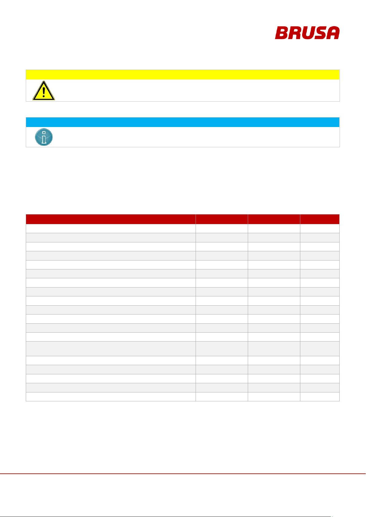
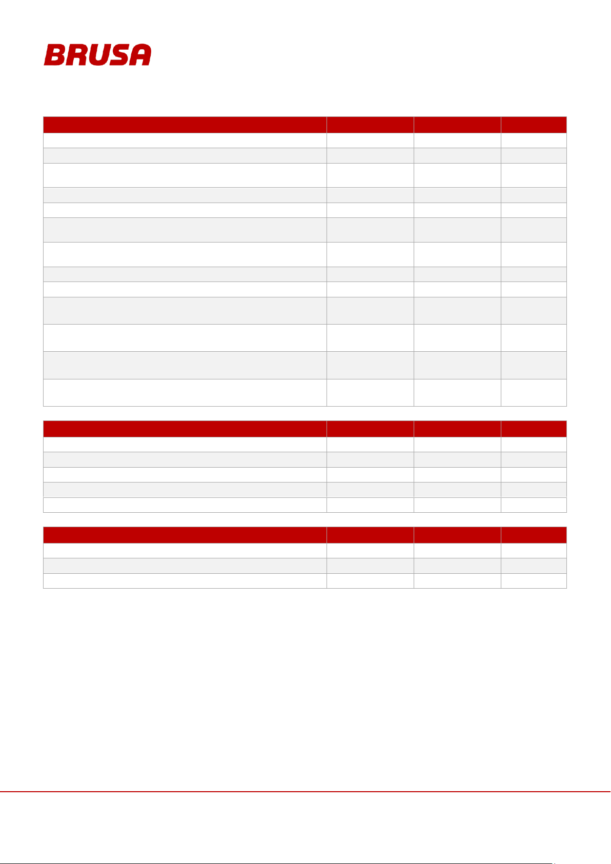
BASIC ELECTRICAL DATA
EVB1-350-40-HP
EVB1-400-40-HP
UNIT
Battery configuration
1P96S
1P108S
---
Capacity (cell)
40
40
Ah
Energy content
14
16
kWh
Technology
Li-Ion
Li-Ion
---
Number of cells
96
108
---
Rated voltage
350
400
V
Max. voltage
400
448
V
Min. voltage
290
324
V
Cont. discharging current cont.
320 (112)
320 (128)
A (kW)
Peak discharging current (specified derating)
600 (120)
600 (240)
A (kW)
Cont. charging current
120 (42)
120 (48)
A (kW)
Internal resistance at 25°C
120 – 140
130 - 150
mΩ
Battery protection (internal)
600 (500)
600 (500)
A (V)
Driving
CAN-Bus
(500 Kbit/s, 1 Mbit/s)
CAN-Bus
(500 Kbit/s, 1 Mbit/s)
---
Peak inrush current of the contactors
2 x 3.7
2 x 3.7
A
Holding current of the contactors
2 x 0.11
2 x 0.11
A
BMS consumption when internal fan output = 100%
3.6
3.6
A
BMS consumption when internal fan output = 50%
2.1
2.1
A
BMS consumption when internal fan output = 0%
0.75
0.75
A
6 About This Device
6.1 Technical Data
Page 28
Technical data
and start-up
EVB1-350/400-40-HP
28
THERMAL / COOLING SYSTEM
EVB1-350-40-HP
EVB1-400-40-HP
UNIT
Amount of coolant in device
ca. 400
ca. 450
ml
External diameter of cooling water connection pieces
16
16
mm
Recommended coolant temperature range at inlet
+ 5 to
+ 20
+ 5 to
+ 20
°C
Minimum coolant temperature at inlet
0 0 °C
Maximum coolant temperature at inlet
< + 40
< + 40
°C
Coolant pressure drop @ 2l/min, T
coolant
= 25°C
(with a water to glycol mixture ratio of 50 / 50)
7 7 mbar
Coolant pressure drop @ 6l/min, T
coolant
= 25°C
(with a water to glycol mixture ratio of 50 / 50)
66
66
mbar
Maximum pressure of the coolant
1 1 bar
Water cooler power
ca. 900
ca. 1000
W
Ambient temperature range - discharge
- 10 to
+ 55
- 10 to
+ 55
°C
Ambient temperature range - charge
+ 10 to
+ 45
+10 to
+ 45
°C
Ambient temperature range - storage < 365 days
-20 to
+25
-20 to
+25
°C
Ambient temperature range - storage < 90 days
-20 to
+40
-20 to
+40
°C
BASIC MECHANICAL DATA
EVB1-350-40-HP
EVB1-400-40-HP
UNIT
Weight (without cooling water)
ca. 130
ca. 145
kg
Length without BMS (with BMS)
662 (770)
736 (844)
mm
Width
515
515
mm
Height without fastening bars (with fastening bars)
284 (304)
284 (304)
mm
IP protection
IP65
IP65
---
CONNECTIONS
EVB1-350-40-HP
EVB1-400-40-HP
UNIT
HV+, HV- high voltage: 2 M8 cable lugs, recommended cable diameter
50
50
mm2
M8 cable lug ground connection, recommended wire diameter
35
35
mm2
23-pole AMP, wire diameter
0.5
0.5
mm2
6.2 Technical Properties
Measurement of the highest and lowest cell voltage in 1 ms cycles
Measurement of the highest and lowest temperature in 1 ms cycles
Relaying of all cell data via CAN within 100 ms
Ah meter with DoD management (current measurement)
Balancing and discharging of individual cells is possible
CAN BUS driving
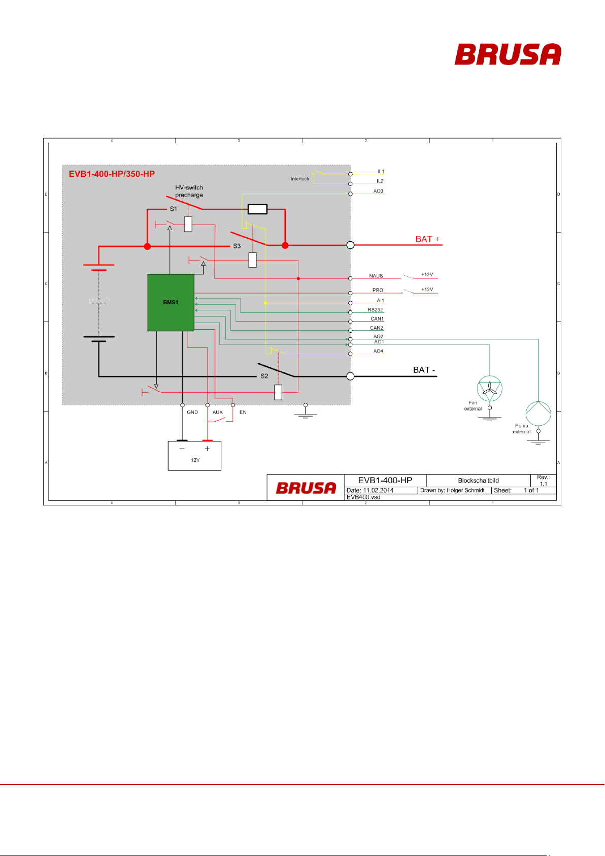
Integrated automatic pre-charge installation (3 HV contactors),
see chapter 6.6.1 EVB1-400/350-40-HP Block Circuit Diagram
Two PWM outputs for driving the water pump and external fan unit
Current measurement of up 768 A possible
Possibility for parallel connection of several batteries
Page 29
29
Technical data
and start-up
EVB1-350/400-40-HP
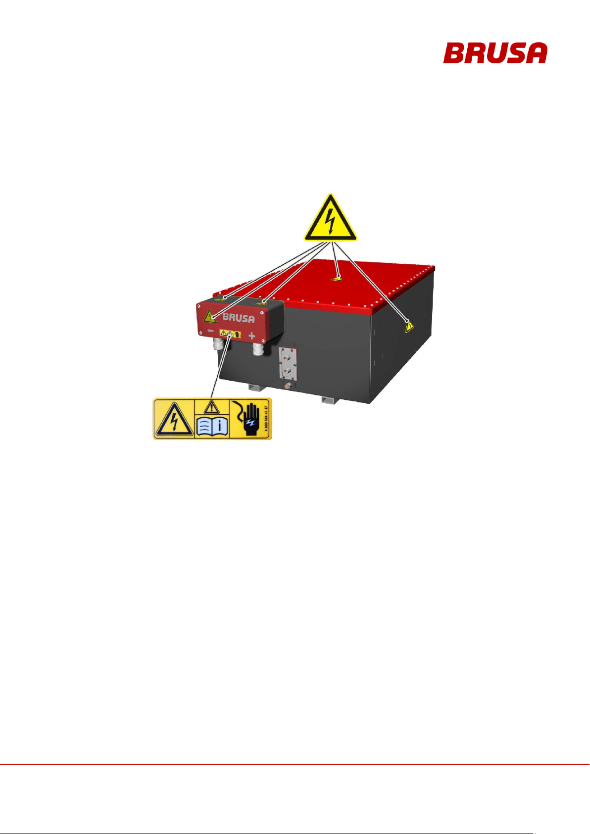
6.3 Warning Instructions on the Battery
Warning signs are attached to the battery to warn the operator of possible dangers. Should one of these warning
signs be missing or become illegible due to wear and tear, it must be renewed immediately! To get an original
label, please contact BRUSA support at the manufacturer address given in chapter 4.6 !
Page 30
Technical data
and start-up
EVB1-350/400-40-HP
30
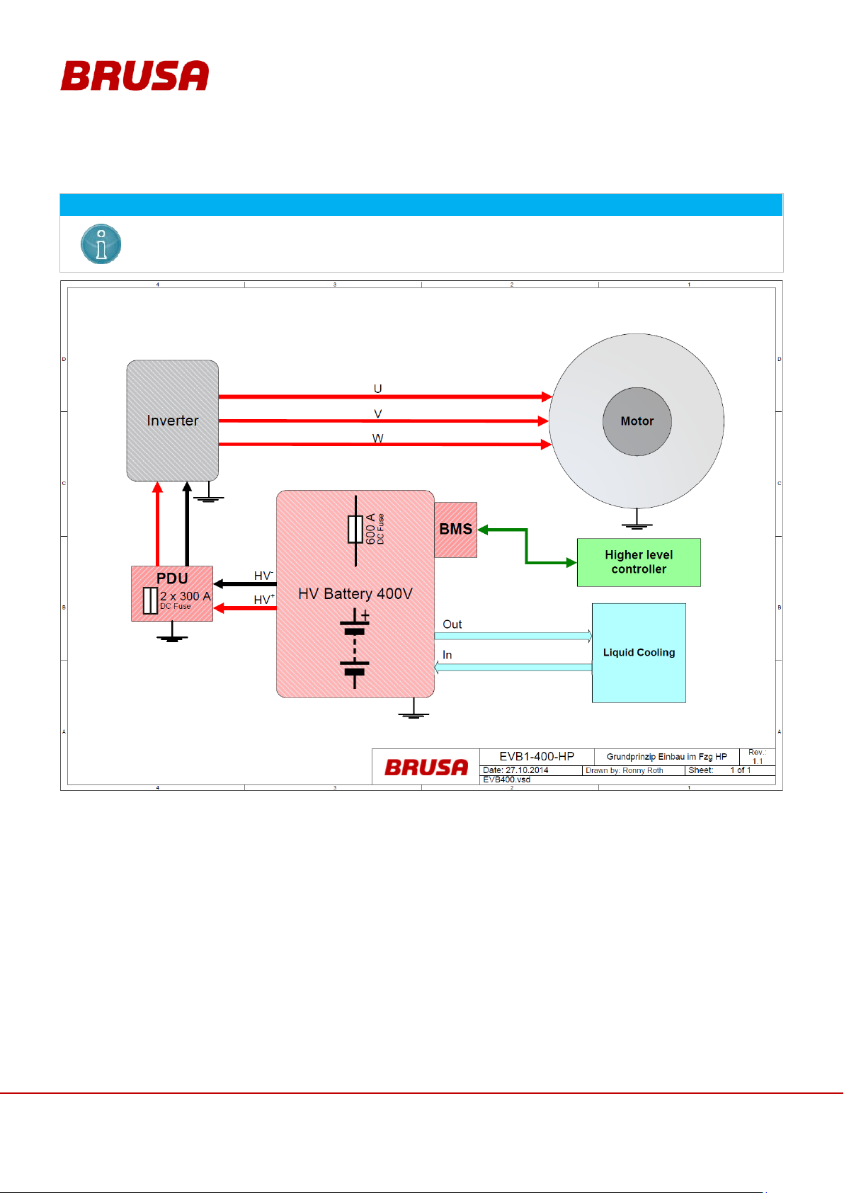
INSTRUCTION
The installation of a PDU is imperative, to protect the battery as well as any peripheral devices from
voltage peaks, short-circuit situations and the serious damages resulting from these!
The PDU should be safeguarded with a 300 A fuse. The battery has a 600 A DC semiconductor fuse.
6.4 Basic Principle for Vehicle Installation
Page 31
31
Technical data
and start-up
EVB1-350/400-40-HP
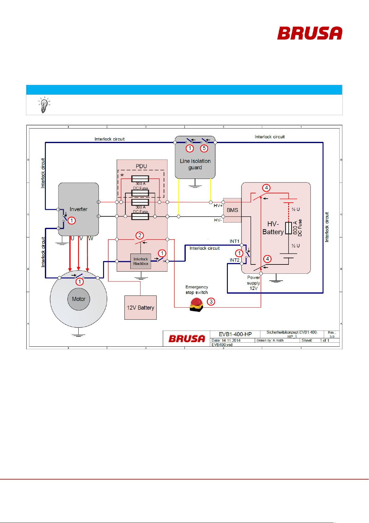
6.5 Safety measures for vehicle installation
INFORMATION
This safety measure is a recommendation by the company BRUSA Elektronik AG and is understood
as a basic requirement for the safe operation of electric vehicles!
*That’s a special assembling with parallel bus bars in the PDU. If it necessary please contact BRUSA Elektronik
AG 4.6
6.5.1 Principle of operation Interlock
The interlock switch (1) is closed if the corresponding interlock condition of each devices is met (closed service
cover, plugged HV connections ...). The interlock evaluation of the PDU switches the 12V supply voltage (2) of the
HV contactors (4) in the battery if the interlock circuit is closed. The emergency stop switch (3) also interrupts the
12V supply voltage of the HV contactors (4). The second interlock (5) of the line insulation guard interrupts the
interlock circuit, if a fault in the HV- insulation is detected.
Page 32

Technical data
and start-up
EVB1-350/400-40-HP
32
6.6 Basic Function Batterie EVB1-400/350-40-HP
The battery EVB1-400/350-40-HP is designed and intended for fast and easy installation in electric vehicles.
Integrated pre-charge switching and the driving via CAN bus enable simple and problem-free integration into an
existing drive train. Through the integrated battery management system (BMS), the highest and lowest cell
voltages are continually communicated via CAN. The individual cell temperatures as well as their states of charge
are also sent this way. This way the entire battery can be continually monitored. If faults or errors occur, the BMS
sends a corresponding signal immediately via CAN to the higher-level control. If this is not reacted to accordingly,
then the battery disconnects itself from the DC intermediate circuit to ensure the battery's secure state. In principle
the battery never actually disconnects from the DC intermediate circuit as long as none of the following limits within
the CAN message Batt_Range are surpassed:
maximum discharging current (CAN signal BATT_CurrentDischargeMax)
maximum charging current (CAN signal BATT_CurrentChargeMax)
minimum battery voltage (CAN signal BATT_Voltage_Min)
maximum battery voltage (CAN signal BATT_Voltage_Max)
The higher than average energy and power density together with the proportionately low weight produce a very
good performance and enable usage in both areas of high performance electric vehicles and in range extender
systems in particular.
Page 33
33
Technical data
and start-up
EVB1-350/400-40-HP
6.6.1 EVB1-400/350-40-HP Block Circuit Diagram
Page 34
Technical data
and start-up
EVB1-350/400-40-HP
34
INFORMATION
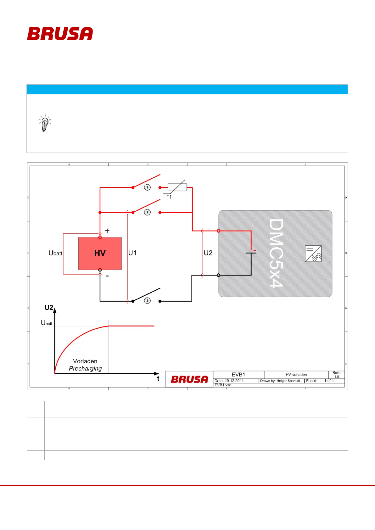
To avoid sparks when switching on, the connected loads are pre-charged with a 50 ohm PTC.
For this process, three independent voltage measurements are used.
The switching on of the battery (switching of the main contactors during pre-charging) is very
easily heard and can therefore be used as a monitor.
The pre-charging resistor is heated up by a succession of repeated (3-4 times) periods of pre-
charging. If overheating occurs then further pre-charging is temporarily not possible. In this case,
the pre-charging resistor must be cooled down over a particular period of time.
1.
Pre-charging contactor (1) closes.
U1 must be at the same level as the sum of the cells (U
batt
). There must be no current flowing.
2.
Main contactor (3) closes.
U2 must rise to the same level as U1 within 5 s. Current < = 4 A.
If the level is not reached, the CAN signal BMS_Err_PreCharge is emitted!
3.
Main contactor (2) closes.
4.
Pre-charging contactor (1) opens.
6.6.2 Pre-charging Voltage
Page 35

35
Technical data
and start-up
EVB1-350/400-40-HP
6.6.3 Temperature Measurement / Temperature Monitoring
Step 1: Warning
If a defined temperature value is reached or exceeded, the warning message or CAN signal
BMS_War_OverTemperature or BMS_War_UnderTemperature will be emitted.
Step 2: Reaching of the Limit
If the defined limit is reached or exceeded, this signifies a charging current of 0 A set by derating
(BATT_CurrentDischargeMax / BATT_CurrentChargeMax).
The CAN signal BMS_MODE_OTP or BMS_MODE_UTP is emitted.
Step 3: Reaching of the maximum value:
If the defined maximum value is reached or exceeded, the battery immediately disconnects from the DC
intermediate circuit, when a current flows.
The error message or the CAN signal BMS_TErr_OverTemperature / BMS_TErr_UnderTemperature is
emitted.
The temperature measurement takes place over one sensor per cell packet. In this, temperature is measured over
18 sensors in total. The highest (CCU_T_HIGH), the lowest (CCU_T_LOW) and the average temperature value
(BATT_T_AVERAGE) can be emitted as an output value. Along with the voltage value, the temperature value per
cell block is emitted with the relevant index in the message CCU_Cell (CCU_T). In each case, the limit is
CCU_T_HIGH.
The temperature monitoring takes place in three steps:
Page 36
Technical data
and start-up
EVB1-350/400-40-HP
36
INFORMATION
Balancing is an operating mode which can be activated after the charging of the battery has taken
place. Efficient balancing can take several hours. In order to avoid the compromising of vehicle use
during this, we recommend that you leave this operation mode running overnight after battery
charging has taken place (this is equivalent to one balancing cycle).
In connection with the BRUSA NLG5 charging device, this operation mode can be automatically
activated. If using another charging device, this operation mode must be programmed accordingly
first of all.
6.6.4 Balancing
During the Balancing, the BMS discharges some cells which have a higher cell voltage in comparison to other cells.
The difference between the lowest and highest cell voltage should optimally be between 20 - 30 mV maximum. A
difference of < 20mV is not possible here. In general, the lower the difference, the higher the capacity of the
battery.
When balancing is being activated, a lower limit (0.1 V under maximum cell voltage) is determined for balancing.
This means that each cell can be reduced by 0.1 V at the most per balancing cycle. Balancing is carried out at a
cell voltage of 4 V with 800 mW capacity. That corresponds to a resistance value of 20 ohms.
Balancing is automatically switched off as soon as the cell voltages are in the optimum range. Balancing can also
be cancelled at any time by the higher level control using the CAN signal BMS_CMD_BALANCING_EN = OFF.
When the battery is in its fully charged state we recommend that you run balancing as soon as there is a difference
value of 50 mV between the cells. From a difference value of 100 mV, it is strongly recommended that balancing is
carried out because at this stage the capacity is already significantly reduced. When the battery is in its discharged
state, difference values within a range of 200 - 400 mV are normal.
Page 37
37
Technical data
and start-up
EVB1-350/400-40-HP
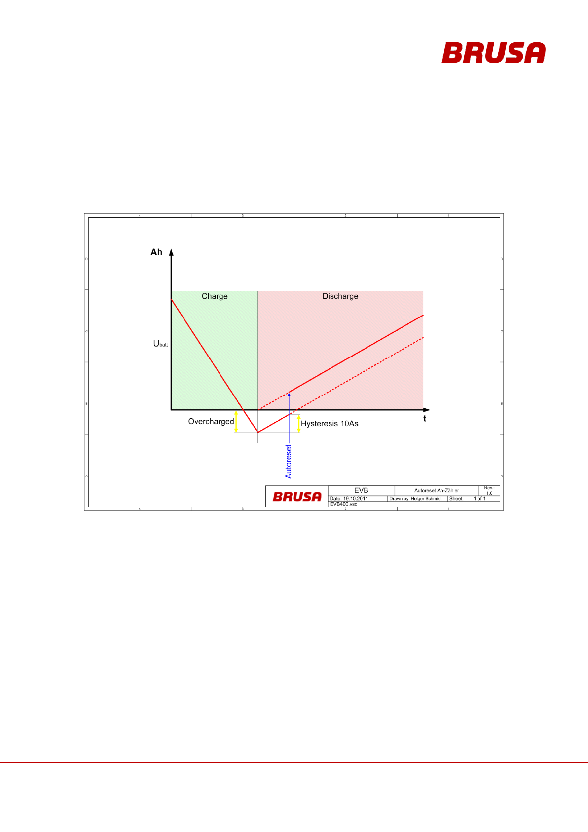
6.6.5 Auto-reset of the Ah Meter
This function ensures that, after the battery has been fully charged, the meter resets to 0 Ah (0% DoD). Without
this function, the Ah meter would constantly shift because the battery loss could not be factored into the calculation,
despite being picked up by the Ah meter. Auto-reset is carried out after a short discharging time of 10 As and
through this the meter reading is set to the corresponding value. This value is given using the signal BCM_Ah. The
loss can be read as negative ampere-hours before discharging.
Page 38
Technical data
and start-up
EVB1-350/400-40-HP
38
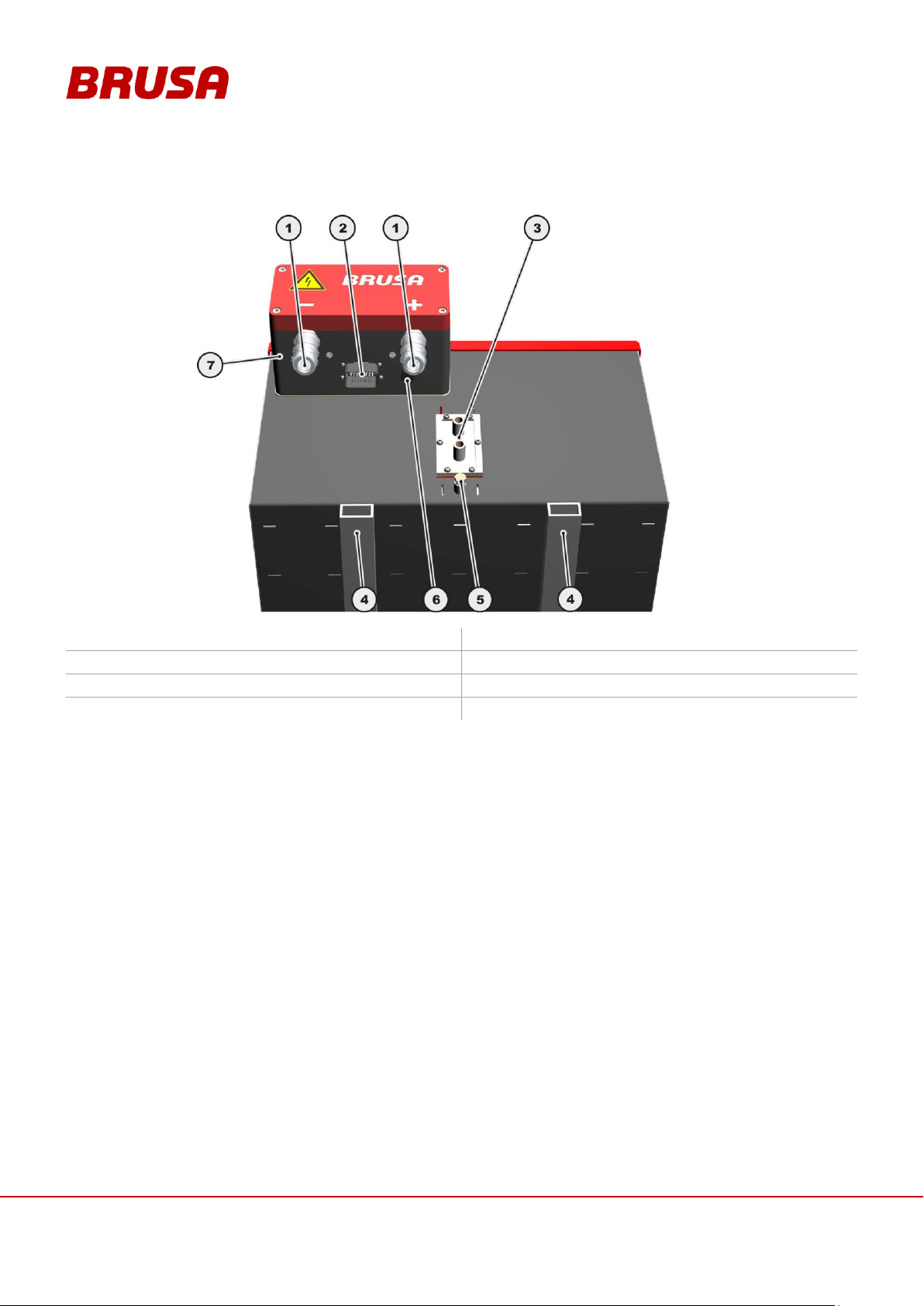
1. HV connections
2. Control connector
3. Cooling water connections
4. Square profile 40 x 20 x 3 mm
5. Grounding screw GND
6. Pressure balance membrane
7. BMS (battery management system)
6.7 Overview of the Main Structural Components
Page 39
39
Technical data
and start-up
EVB1-350/400-40-HP
6.8 Dimensions and Installation Information
CAUTION
Damage to the Battery!
The battery may only be installed horizontally (+/- 10°) (HV connections downwards)! A deviating
installation position can lead to damages to the battery!
Even if the battery has a high IP protection, install it well above the fording depth of the vehicle.
Under no circumstances should mechanical changes be made to the battery housing (drilling,
screwing, clamping, use of brute strength and the like)!
The battery housing should not be mechanically loaded on either side in its installed state! Under
no circumstances should objects of any kind be placed or mounted on the cover! This can lead to
the malfunction of the battery!
INSTRUCTION
The battery must always be handled using additional accident prevention measures during vehicle
installation! This can be done for example through the installation of a special safety guard. These
installations must be cleared beforehand with the responsible institution for road safety (e.g. TÜV).
INFORMATION
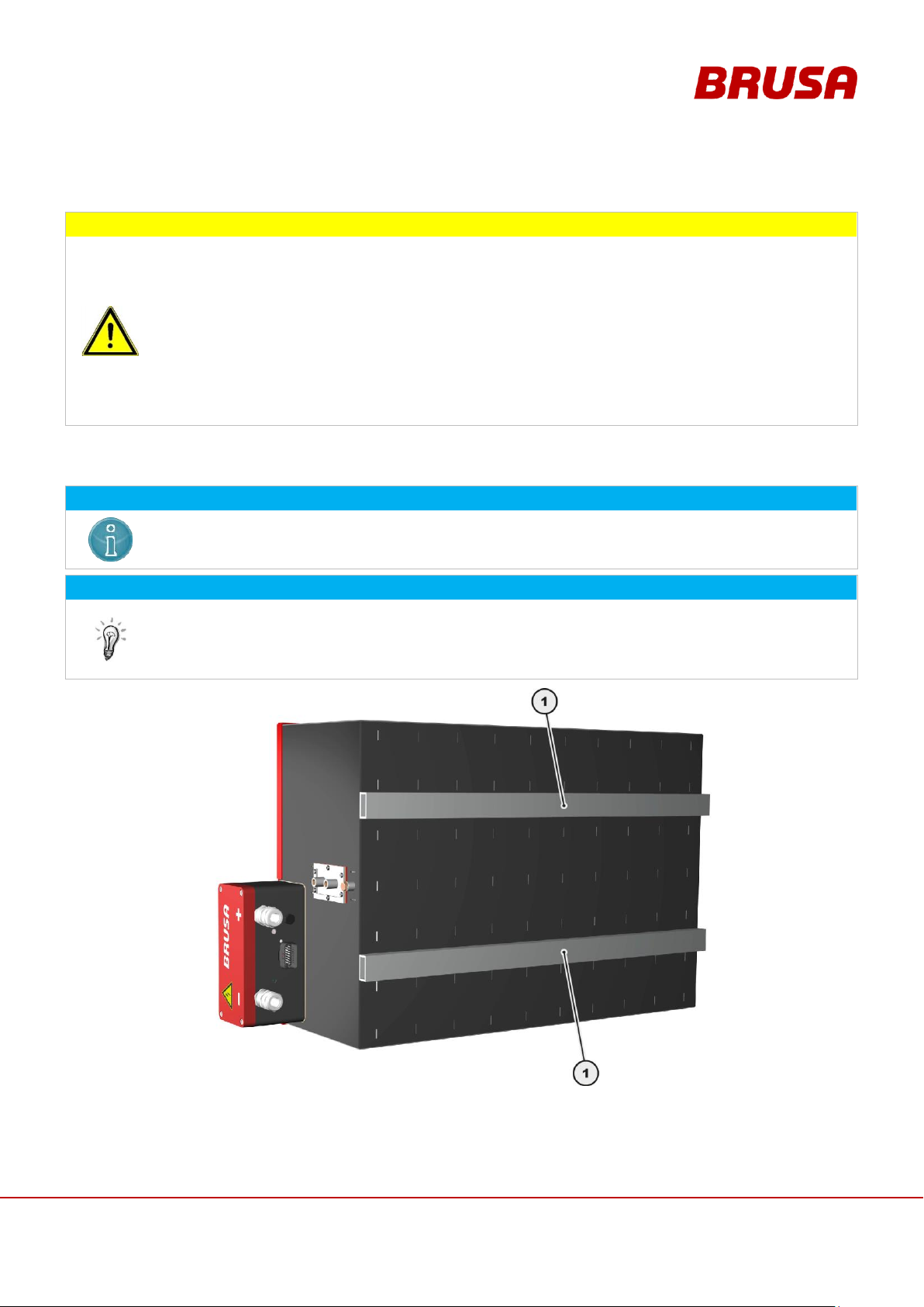
2 square profile pieces are welded to the underside of the battery. The fixing points can be
individually fitted. On account of the net weight we recommend fixing at least 6 M8 screw joints per
square profile.
The fixing can be done using M8 dimension rivet nuts.
1. Square profile 40 x 20 x 3 mm
6.8.1 Fixing Points
Page 40
Technical data
and start-up
EVB1-350/400-40-HP
40
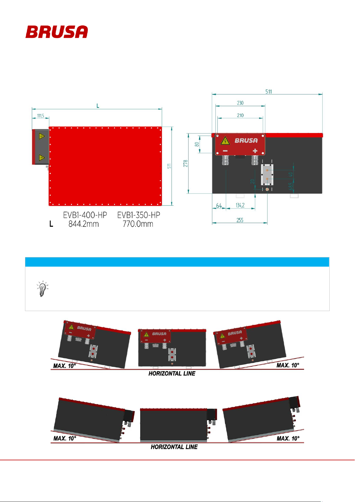
6.8.2 Dimensions
INFORMATION
In principle the battery should be installed in a horizontal position (underside of the battery in a
horizontal direction). A maximum gradient of 10° degrees on each side is permitted here (see
diagram). Installation positions deviating from this hold additional dangers and lead to damage to the
battery!
Larger inclination angles resulting from different driving situations (hill ascent, descent) have no
negative influences because these are only in effect for short periods of time.
6.8.3 Installation Position
Page 41
41
Technical data
and start-up
EVB1-350/400-40-HP
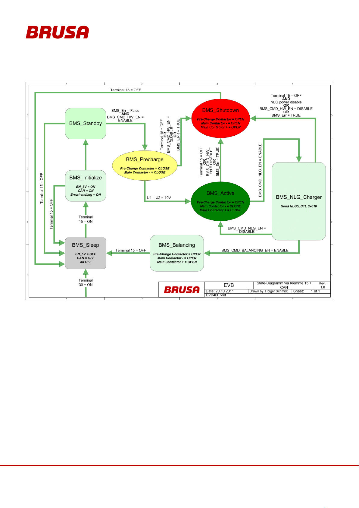
6.9 Regulation and Control System
INFORMATION
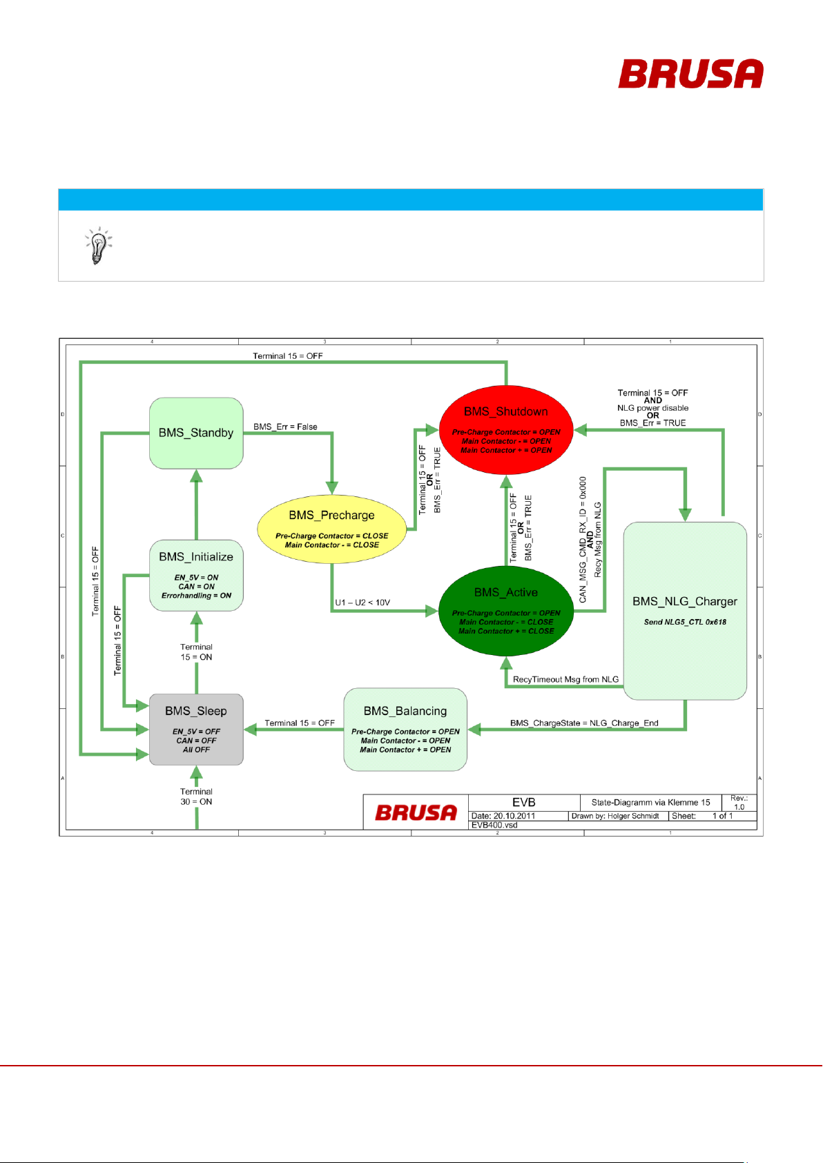
In principle, the battery can be switched on independently by the vehicle control system via terminal
15 or via CAN bus.
If the battery is switched on via terminal 15, the ID of the parameter Rx_CMD must be set to the value
0 in the PARAM software.
6.9.1 Control via Terminal 15 (without CAN Bus)
Page 42
Technical data
and start-up
EVB1-350/400-40-HP
42
6.9.2 Control via Terminal 15 with Driving via CAN
Page 43
43
Technical data
and start-up
EVB1-350/400-40-HP
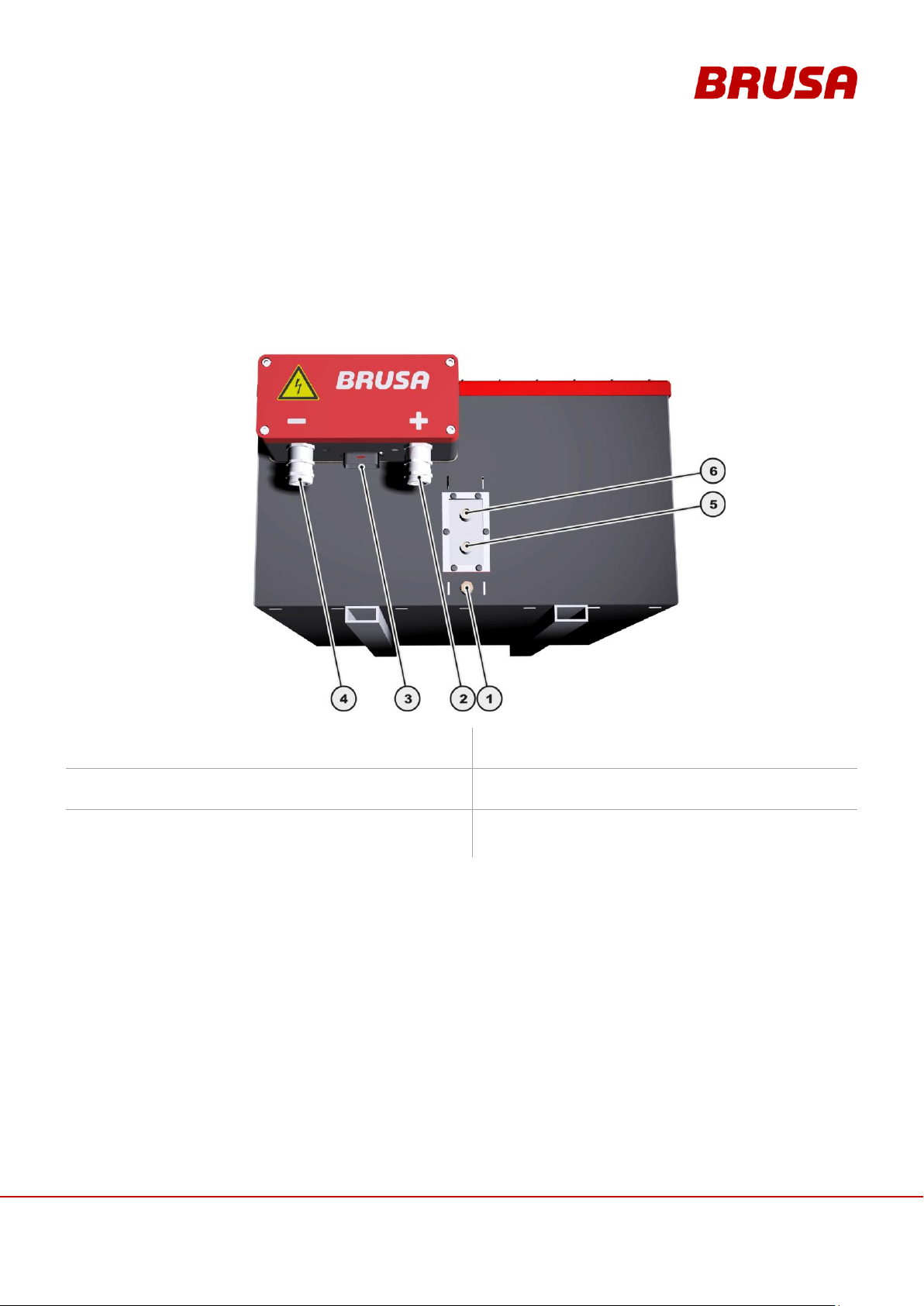
7 Connections
1. Ground (GND)
chapter 7.2 Ground (GND)
2. High voltage+ (HV Plus)
3. Control connector
chapter 7.2 Ground (GND)
4. High voltage- (HV negative)
5. Cooling water outlet ø 15 mm
(Inner diameter of cooling water pump 14 mm)
6. Cooling water inlet ø 15 mm
(Inner diameter of cooling water pump 14 mm)
7.1 Circuit Connections
You will find the required cable types and diameters in chapter 6.1 Technical Data
Page 44
Technical data
and start-up
EVB1-350/400-40-HP
44
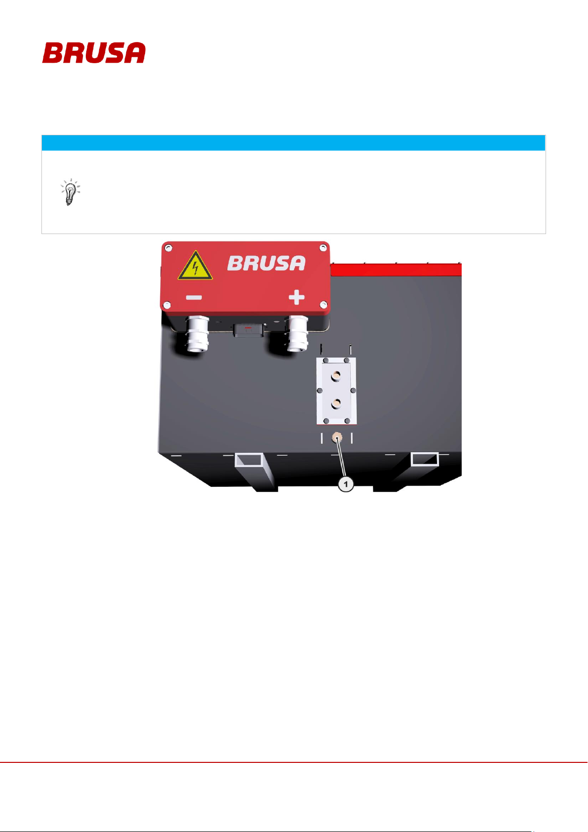
INFORMATION
The grounding screw (1) must be connected with the earth of the vehicle and/or testing bay.
We generally recommend connecting the grounding wires of all drive components collectively to
one ground pin. This minimises the risk of potential differences which can lead to the dysfunction
of specific drive components!
The cable diameter of the ground cable must correspond to the dimensions of the HV wiring.
Torque earthing screw (1) M8 x 10 = 10 Nm
7.2 Ground (GND)
Page 45
45
Technical data
and start-up
EVB1-350/400-40-HP
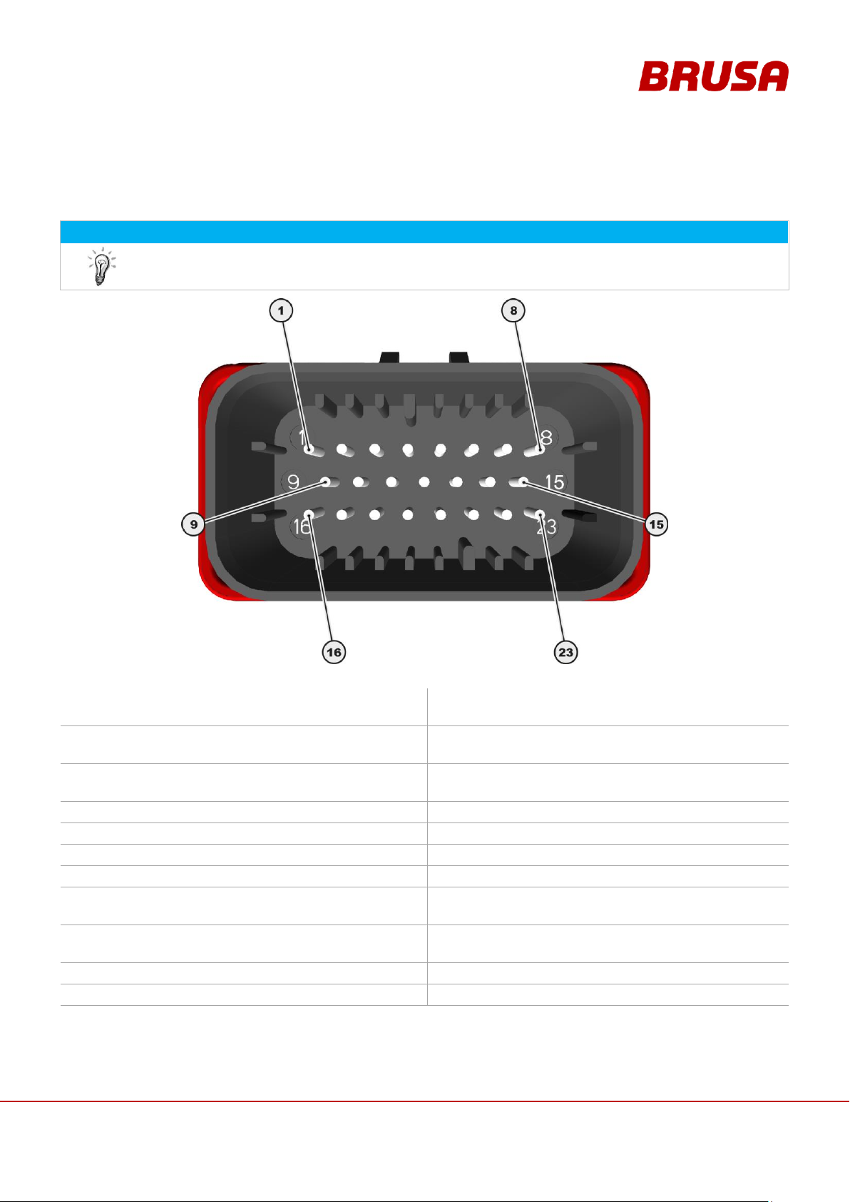
7.3 Pin Assignment of Control Plug (Device-side)
INFORMATION
For a continuity check on the HV interlock pins (INT1, INT2), the multimeter must be set to the diode
measurement setting because a bi-directional optocoupler is installed.
1.
GND
Earth (minus wiring system,
terminal 31)
2.
AUX
+12 V (plus wiring system,
terminal 30)
3.
EN
Enable (power ON, terminal 15)
4.
PWML
PWM-out
External fan
5.
PWMP
PWM-out
External pump
6.
CAN2L*
Reserve
7.
CAN2H*
Reserve
8.
APG
Analogue Protected Ground (RS232)
9.
CAN1L
CAN1 low
10.
CAN1H
CAN1 high
11.
RS232T
RS232 Transmit
12.
RS232R
RS232 Receive
13.
PRO
Enable firmware download
14.
CANG
CAN Ground
15.
RS232G
RS232 Ground
16.
RFK1
Feedback contact 1
(monitoring of redundant contactor)
17.
RFK2
Feedback contact 2
(monitoring of redundant contactor)
18.
RFKC
Shared connection of feedback
contact
19.
INT1
Interlock input
20.
INT2
Interlock output
21.
NAUS
Emergency stop (supply of contactors)
22.
TMP1*
Reserve
23.
TMP2*
Reserve
* = Optional
Page 46
Technical data
and start-up
EVB1-350/400-40-HP
46
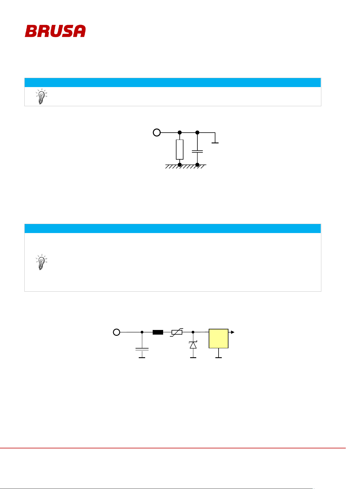
7.3.1 Pin 1 GND
INFORMATION
If the battery control signals are connected with other vehicle components, then the connection to the
vehicle's ground must take place at this pin.
Internal wiring
1MΩ
23,5μF
Pin 1 GND
housing
Direct ground connection of the battery's control electronics.
The signal ground is connected with the battery housing through a few components. These components serve
for self protection and constitute a defined connection.
INFORMATION
We recommend using a 15 A fuse for this pin on the 12 V battery (LV supply).
The voltage range for pin 2 AUX = high is between 9 – 15 V.
The battery is generally ready for operation when the following requirements are met:
Voltage is applied at pin 2 AUX (terminal 30)
Pin 3 EN is high
Pin 1 GND (terminal 31) is connected
No error messages present
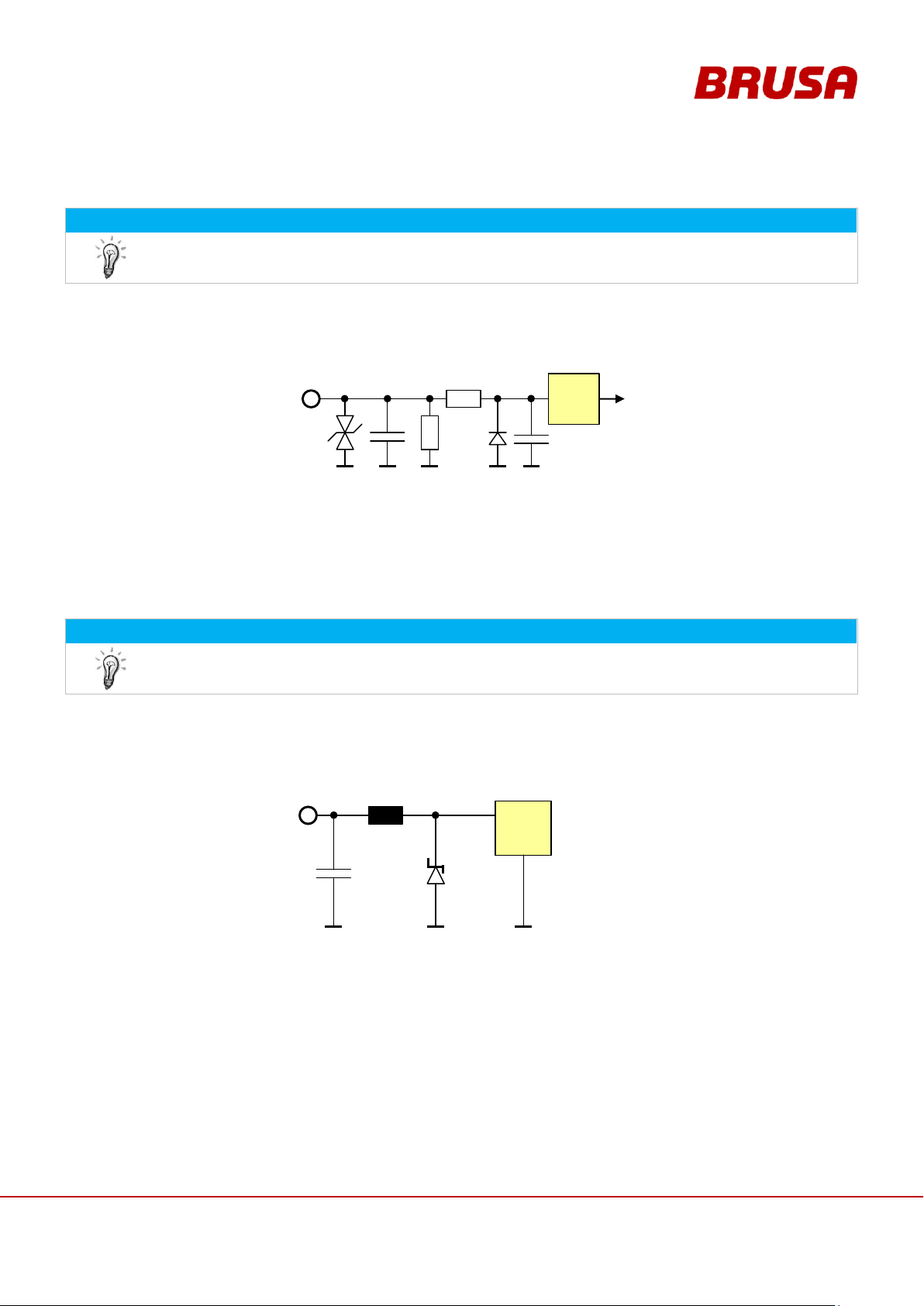
Internal wiring
7,5μH
1,76μF
Pin 2
AUX
Internal
Supply
PTC
9A
33V
The internal 5 V supply is generated with this pin and offers the following possibilities:
CAN communication
Microprocessor Programming (Firmware)
7.3.2 Pin 2 AUX
Page 47
47
Technical data
and start-up
EVB1-350/400-40-HP
7.3.3 Pin 3 EN
INFORMATION
To programme new firmware, pin 13 must be PRO = high!
The voltage range for pin 3 EN = high is between 9 – 15 V.
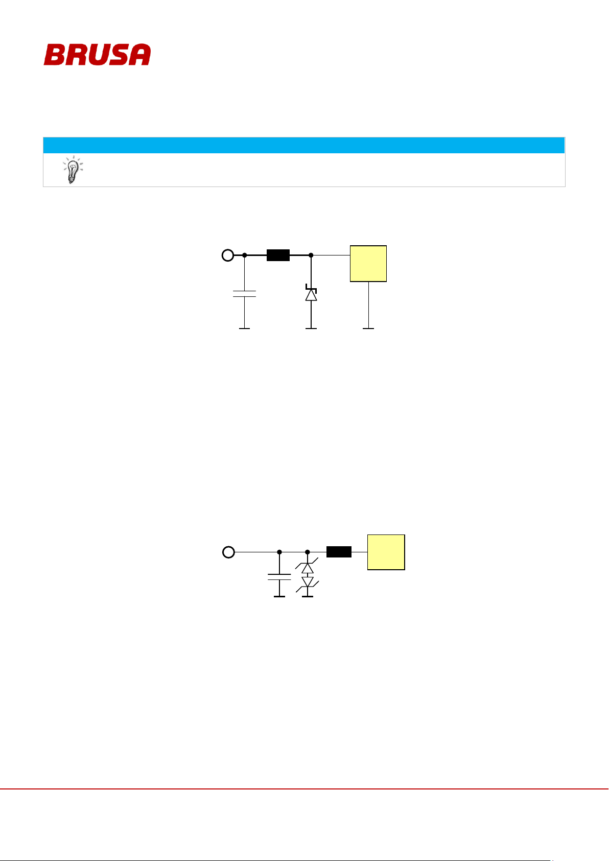
Internal wiring
22k
1k
47nF
4,7V
33V
Schmitt
Trigger
Pin 3
EN
220pF
If voltage is applied at pin 2 AUX and pin 3 is EN = high, this effects the start-up of the controller.
The internal device logic is only fed if pin 3 is EN = high.
Pin 3 EN has the function of terminal 15.
INFORMATION
This PWM-controlled outlet may be charged with 4 A max. (at 12 V)! Programming is carried out
using the software PARAM.
Internal wiring
15µH
4A
165µF
Pin 4
PWML
Cooler
Supply
30V
Via this pin, an external fan can be driven up to 4 A / 12 V, which is controlled by the BMS.
Desired temperature thresholds (switching on / switching off) along with the fan output can be configured in
the software PARAM, see chapter 10.3 Changing the CAN Parameters with PARAM.
7.3.4 Pin 4 PWML / PWM-out
Page 48
Technical data
and start-up
EVB1-350/400-40-HP
48
INFORMATION
This PWM-controlled outlet may be charged with 4 A max. (at 12 V)! Programming is carried out
using the software PARAM.
Internal wiring
15µH
4A
165µF
Pin 5
PWMP
External
Supply
30V
Via this pin, an external pump can be driven up to 4 A / 12 V, which is controlled by the BMS.
Desired temperature thresholds (switching on / switching off) along with the output can be configured in the
software PARAM, see chapter 10.3 Changing the CAN Parameters with PARAM.
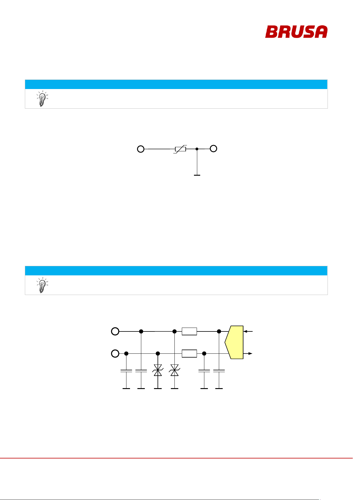
Internal wiring
47pF
Pin 9 CAN1L
Pin 10 CAN1H
51µH
0,5A
33V
CAN
Driver
7.3.5 Pin 5 PWMP / PWM-out
7.3.6 Pin 9 CAN1L, Pin 10 CAN1H
The CAN interface (pin 10) has the following features and/or possibilities:
CAN 2.0 B, 500 kbit (optionally 1 Mbit)
Parameters can be set for CAN IDs.
Termination of the CAN wiring (optional setting of the 120 Ω terminating resistor)
Page 49
49
Technical data
and start-up
EVB1-350/400-40-HP
7.3.7 Pin 8 APG, Pin 14 CANG, Pin 15 RS232G
INFORMATION
The additional earth connections are intended to simplify the external wiring.
Internal wiring
Pin 8 APG
Pin 14 CANG
Pin 15 RS232G
PTC
1,5A
Pin 1
GND
INFORMATION
This interface is NOT intended for general use! It is designed for firmware updates. Should you have
any questions, please contact BRUSA support at the manufacturer address given in chapter 4.6 .
Internal wiring
47pF
33V
47pF
Pin 11 RS232T
33V
RS232-
Transceiver
200Ω
200Ω
470pF
470pF
Pin 11 RS232R
The RS232 port enables a direct, serial connection between the battery and a PC. You can find the
configurations for this in chapter 10.6 Carrying Out Firmware Updates. In this chapter, you will find all
information regarding programming and the settings necessary for it.
The firmware for the microprocessor can be downloaded over this interface (provided by BRUSA). Pin 13
PRO must be high for this.
The pins 8 APG, 14 CANG and 15 RS232G are each connected with pin 1 GND via a reversible fuse (PTC) and
are thereby protected.
The following allocation is recommended:
Pin 8: Analogue Protected Ground
Pin 14: CAN Ground
Pin 15: RS232 Ground
7.3.8 Pin 11 RS232T, Pin 12 RS232R
Page 50
Technical data
and start-up
EVB1-350/400-40-HP
50
7.3.9 Pin 13 PRO
INSTRUCTION
The programming of the wrong firmware can lead to the damage of the battery!
So the programming may only be carried out after consultation with the company BRUSA Elektronik
AG!
INFORMATION
This pin is only activated for the programming of a new firmware (pin 13 PRO = high). Pin 3 EN must
also be high for this.
In normal operation, pin 13 PRO may not be wired or it must be directly connected with terminal 31.
An open circuit can lead to a reset of the battery!
The voltage range for pin 13 PRO = high is between 9 - 15 V.
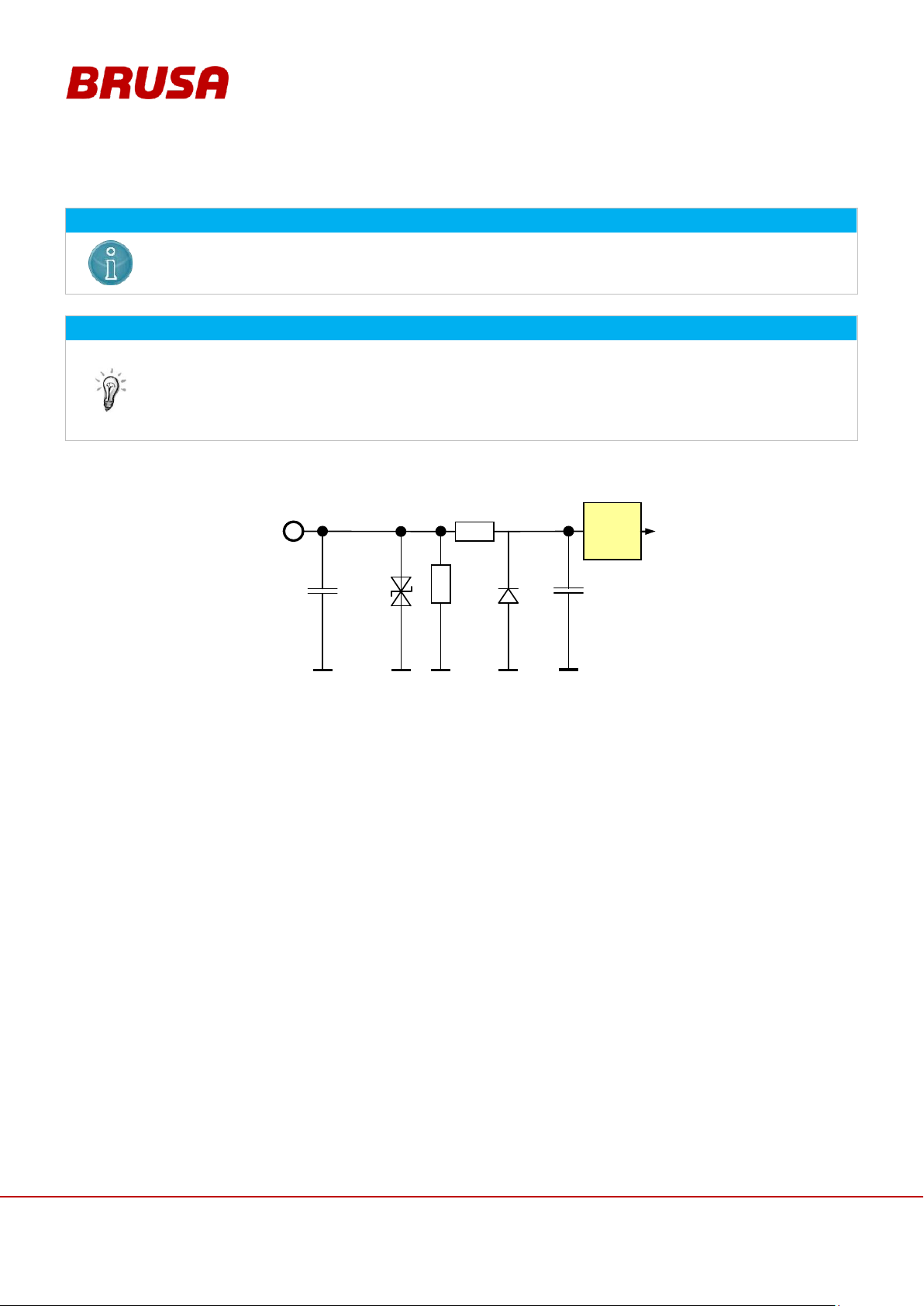
Internal wiring
1,0V
3,3V
47nF
Pin 13 PRO
220pF
Schmitt
Trigger
22kΩ
10kΩ
33V
4,7V
As soon as pin 13 PRO is high, the following processes are activated:
The battery is stopped (reset) if it is in operation.
The programming can now be carried out via the serial interface.
see chapter 10.6 Carrying Out Firmware Updates.
Page 51
51
Technical data
and start-up
EVB1-350/400-40-HP
7.3.10 Pin 16 RFK1, Pin 17 RFK2, Pin 18 RFKC
INFORMATION
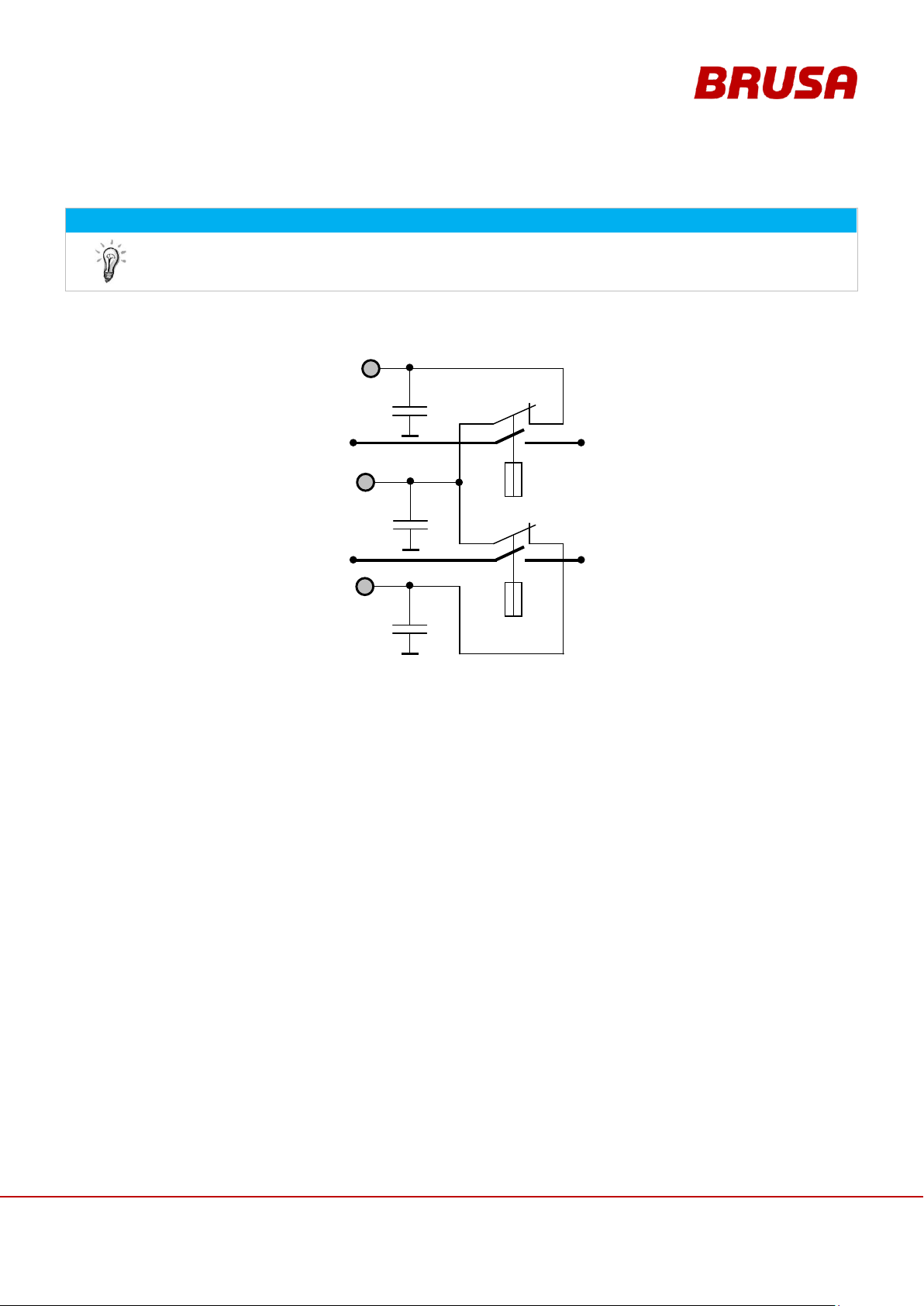
These pins carry out redundant monitoring of each of the contactors from the outside via a switch in
the contactor. This way, whether the contactors are open or closed can be constantly monitored. The
signals can be analysed by the customer accordingly for this monitoring.
Internal wiring
10nF
Pin 17 RFK2
10nF
Pin 18 RFKC
10nF
Pin 16 RFK1
S2 Main
contactor
B-
Normally
open
S3 Main
contactor
B+
Normally
open
HV+
HV-
max. contact current 300 mA @ 12 V
min. contact current 100 mA @ 12 V
(Tyco KILOVAC EV200 Series)
Page 52
Technical data
and start-up
EVB1-350/400-40-HP
52
DANGER
High voltage!
Danger to life!
The bypassing or short-circuiting of safety installations can result in fatal dangers through high
voltage!
The interlock is a security installation and under no circumstances can it be disabled or bypassed!
INFORMATION
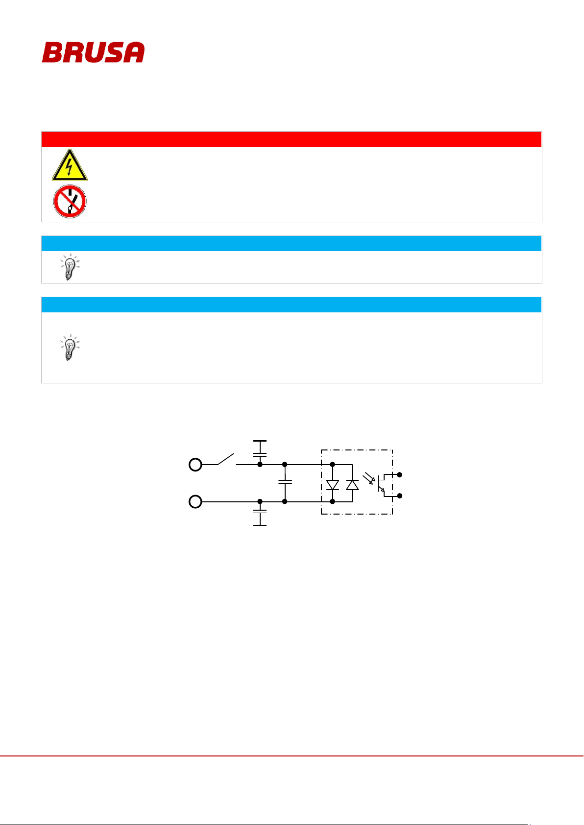
For a continuity check on the HV interlock pins (INT1, INT2), the multimeter must be set to the diode
measurement setting because a bi-directional optocoupler is installed.
INFORMATION
The battery does not react automatically to the interlock signal! This function must be implemented
by the customer by connecting and assessing both pins (pin 19 IL1 and pin 20 IL2) (alternatively via
the BRUSA PDU254)! The shut-down of the battery must therefore take place through the feeding-in
of an external signal (by the customer). As a result, the high voltage connections will be forced to
disconnect immediately! The interlock switch is automatically activated as soon as the service cap is
opened.
Internal wiring
Pin 20 INT2
Pin 19 INT1
Switch opened if
service lid is open
10nF
10nF
100nF
Max. switching voltage = 32 V
Max. switching current = 30 mA
7.3.11 Pin 19 INT1, Pin 20 INT2
Page 53
53
Technical data
and start-up
EVB1-350/400-40-HP
7.3.12 Pin 21 NAUS
INFORMATION
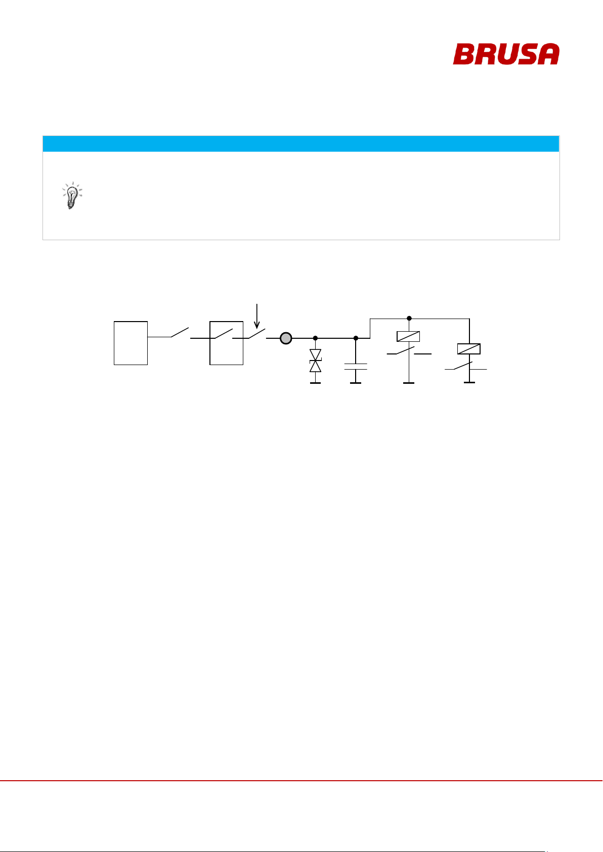
We recommend using a 15 A fuse for this pin on the 12 V battery (LV supply).
The supply of both HV contactors takes place via this pin.
The supply from pin 21 NAUS must temporarily provide 10 A to switch the contactors.
The peak inrush current for the HV contactors is 3.7 A each.
You can find instructions on the functioning of the emergency stop switch in chapter
3.4.6 Emergency Stop Switch.
Internal wiring
470nF
50V
33V
Pin 21
NAUS
PDU
PDU with
Interlock
Battery
12V
Kl.30
HV+
HV+
HV-
HV-
Emergency
stop stitch
Page 54
Technical data
and start-up
EVB1-350/400-40-HP
54
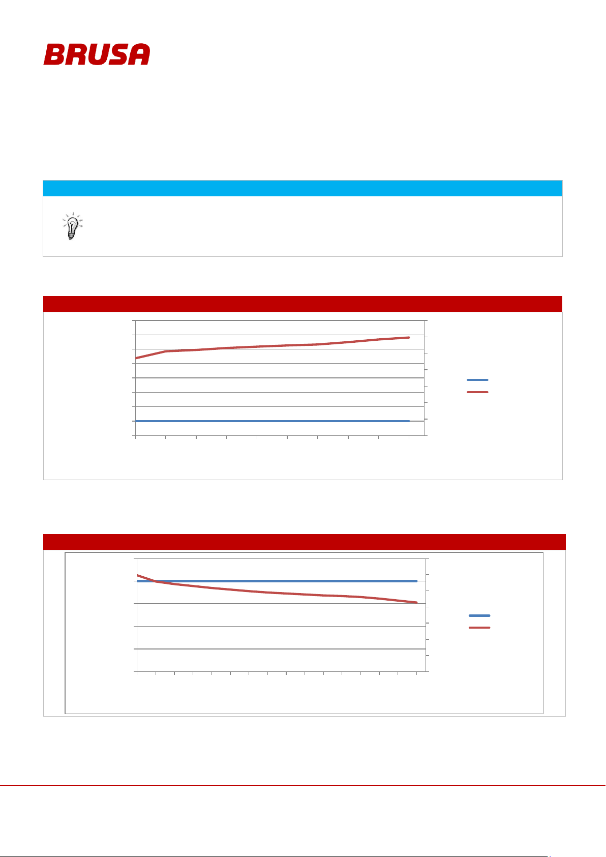
INFORMATION
The following profiles were determined under real environmental conditions.
Room temperature = 25 °C
Cooling water temperature flow = 15 °C
Constant discharging of the battery
CHARGING 120 A
DISCHARGING 80 A
150
200
250
300
350
400
450
500
-140
-120
-100
-80
-60
-40
-20
0
20
0 2 4 6 8 10 12 14 16 18
VOLT
AMPERE
Zeit in min
Current A
Voltage V
150
200
250
300
350
400
450
500
0
20
40
60
80
100
0 2 4 6 8 10 12 14 16 18 20 22 24 26 28 30
VOLT
AMPERE
Zeit in min
Current A
Voltage V
8 Profiles and Diagrams
8.1 Charging / Discharging of Battery
8.1.1 Charging (120 A) EVB1-400-40-HP
8.1.2 Discharging (80A) EVB1-400-40-HP
Page 55
55
Technical data
and start-up
EVB1-350/400-40-HP
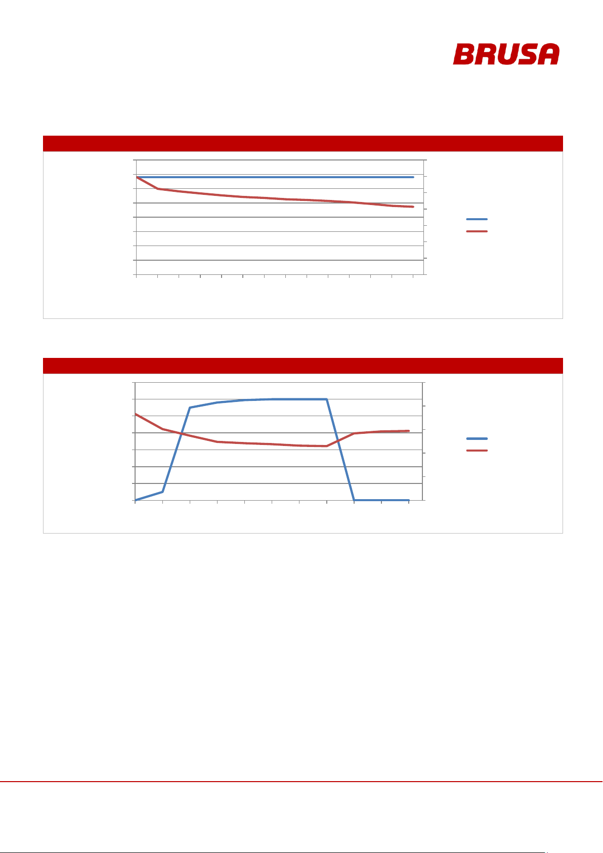
8.1.3 Discharging (320 A peak) EVB1-400-40-HP
DISCHARGING 320 A
DISCHARGING 600 A
150
200
250
300
350
400
450
500
0
50
100
150
200
250
300
350
400
0 0.5 1.5 2 2.5 3 3.5 4 4.5 5 5.5 6 6.5 7
VOLT
AMPERE
Zeit in min
Current A
Voltage V
250
300
350
400
450
500
0
100
200
300
400
500
600
700
0 3 6 9 12 15 18 21 24 27 30
VOLT
AMPERE
Time in s
Current A
Voltage V
8.1.4 Discharging (600 A peak) EVB1-400-40-HP
Page 56
Technical data
and start-up
EVB1-350/400-40-HP
56
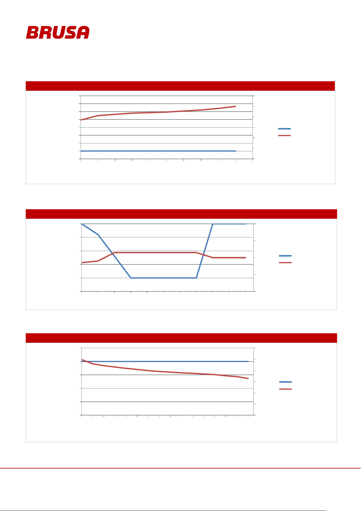
CHARGING 120 A
CHARGING 200 A
DISCHARGING 80 A
150
200
250
300
350
400
450
-140
-120
-100
-80
-60
-40
-20
0
20
0 2 4 6 8 10 12 14 16 18 20
VOLT
AMPERE
Zeit in min
Current A
Voltage V
250
300
350
400
450
-250
-200
-150
-100
-50
0
0 3 6 9 12 15 18 21 24 27 30
VOLT
AMPERE
Time in s
Current A
Voltage V
150
200
250
300
350
400
450
0
20
40
60
80
100
0 2 4 6 8 10 12 14 16 18 20 22 24 26 28 30
VOLT
AMPERE
Zeit in min
Current A
Voltage V
8.1.5 Charging (120 A) EVB1-350-40-HP
8.2 Discharging (200 A) EVB1-350-40-HP
8.2.1 Discharging (80 A) EVB1-350-40-HP
Page 57
57
Technical data
and start-up
EVB1-350/400-40-HP
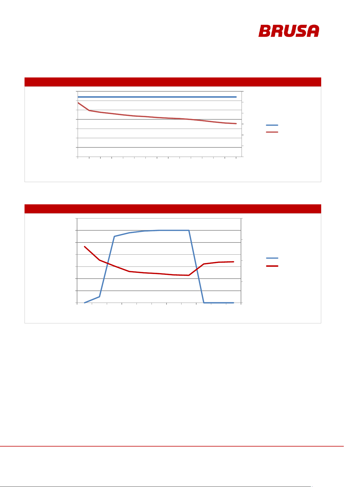
8.2.2 Discharging (320 A peak) EVB1-350-40-HP
DISCHARGING 320 A
DISCHARGING 600 A
150
200
250
300
350
400
450
0
50
100
150
200
250
300
350
0 0.5 1 1.5 2 2.5 3 3.5 4 4.5 5 5.5 6 6.5 7
VOLT
AMPERE
Zeit in min
Current A
Voltage V
250
300
350
400
450
0
100
200
300
400
500
600
700
0 3 6 9 12 15 18 21 24 27 30
VOLT
AMPERE
Time in min
Current A
Voltage V
8.2.3 Discharging (600 A peak) EVB1-350-40-HP
Page 58
Technical data
and start-up
EVB1-350/400-40-HP
58
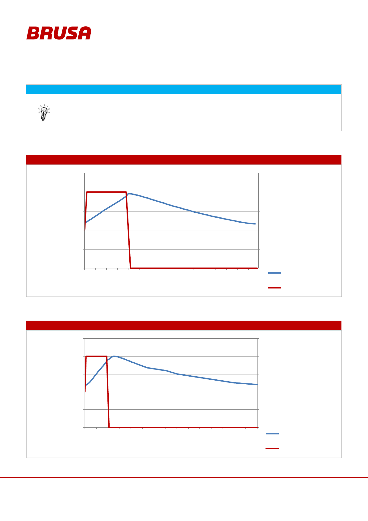
INFORMATION
The following profiles were determined under real environmental conditions.
Room temperature = 25 °C
Fan output 100%
Constant discharging of the battery at 120 A (corresponds to around 48 kW output)
COOLING WATER INLET TEMPERATURE +5°C
COOLING WATER INLET TEMPERATURE +15°C
0
30
60
90
120
150
0
10
20
30
40
50
0 5 10 15 20 25 30 35 40 45 50 55 60 65 70 75
Ampere
° Celsius
Time in min
Temperatur [C]
Strom [A]
0
30
60
90
120
150
0
10
20
30
40
50
0 10 20 30 40 50 60 70 80 90 100 110 120 130 140 150
Ampere
° Celsius
Time in min
Temperatur [C]
Strom [A]
Temperature [°C]
Current [A]
Temperature [°C]
Current [A]
8.3 Temperature / Cooling System
8.3.1 Cooling Behaviour at Cooling Water Inlet Temperature +5°C
8.3.2 Cooling Behaviour at Cooling Water Inlet Temperature +15°C
Page 59
59
Technical data
and start-up
EVB1-350/400-40-HP
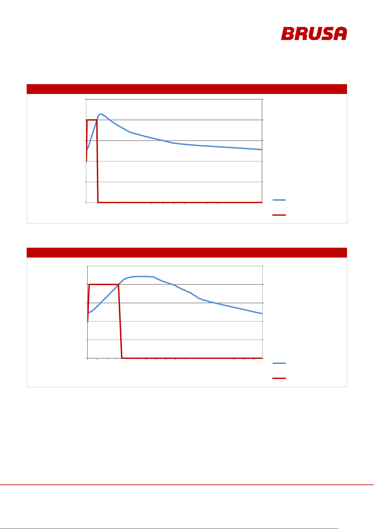
8.3.3 Cooling Behaviour at Cooling Water Inlet Temperature +25°C
COOLING WATER INLET TEMPERATURE +25°C
COOLING CIRCUIT DEACTIVATED
0
30
60
90
120
150
0
10
20
30
40
50
0 20 40 60 80 100 120 140 160 180 200 220 240 260 280 300 320
Time in min
Ampere
° Celsuis
Temperatur [C]
Strom [A]
0
30
60
90
120
150
0
10
20
30
40
50
0.0
0.1
0.2
0.3
0.4
0.5
0.6
1.0
2.0
3.0
5.0
9.0
15.0
21.0
27.0
33.0
39.0
45.0
Ampere
° Celsius
Time in h
Temperatur [C]
Strom [A]
Temperature [°C]
Current [A]
Temperature [°C]
Current [A]
8.3.4 Cooling Behaviour without Active Cooling (Cooling Circuit Deactivated)
Page 60
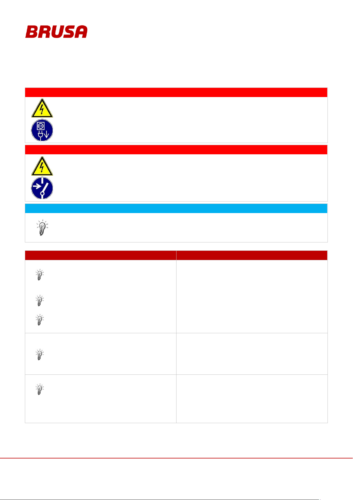
Technical data
and start-up
EVB1-350/400-40-HP
60
DANGER
High voltage!
Danger to life!
When the battery is switched on, the HV connections are under high voltage! Never remove the BMS
cover when the battery is switched on!
You must pull out the control plug before you remove the BMS cover!
DANGER
High voltage!
Danger to life!
Despite faults being present the HV wiring can still be under high voltage! Always shut down the HV
supply via the emergency stop before starting work on the battery!
The customer must install a large, easily accessible emergency stop switch, we recommend
connecting it (interlock and emergency stop) via the PDU.
INFORMATION
Make visual checks on the packing material and the device itself in particular for damages before
installation. Each device undergoes a strict quality and function test at BRUSA before distribution.
However, we have no control over transportation routes which can sometimes take a long time and
the shipping of our products.
PROCEDURE STEP
ILLUSTRATION / OTHER INFORMATION
1.
Unpack the battery.
See chapter 0
Unpacking the Battery
---
2.
Insert the battery into position and connect the
mechanical coupling components.
Please adhere to the installation instructions,
see chapter 6.8.1 Fixing Points
---
3.
Wire up the control plug.
See chapter 7.3 Pin Assignment of Control Plug
(Device-side)
See chapter 6.6.1 EVB1-400/350-40-HP Block
Circuit Diagram
---
9 Installation / Initial Start-up
Page 61
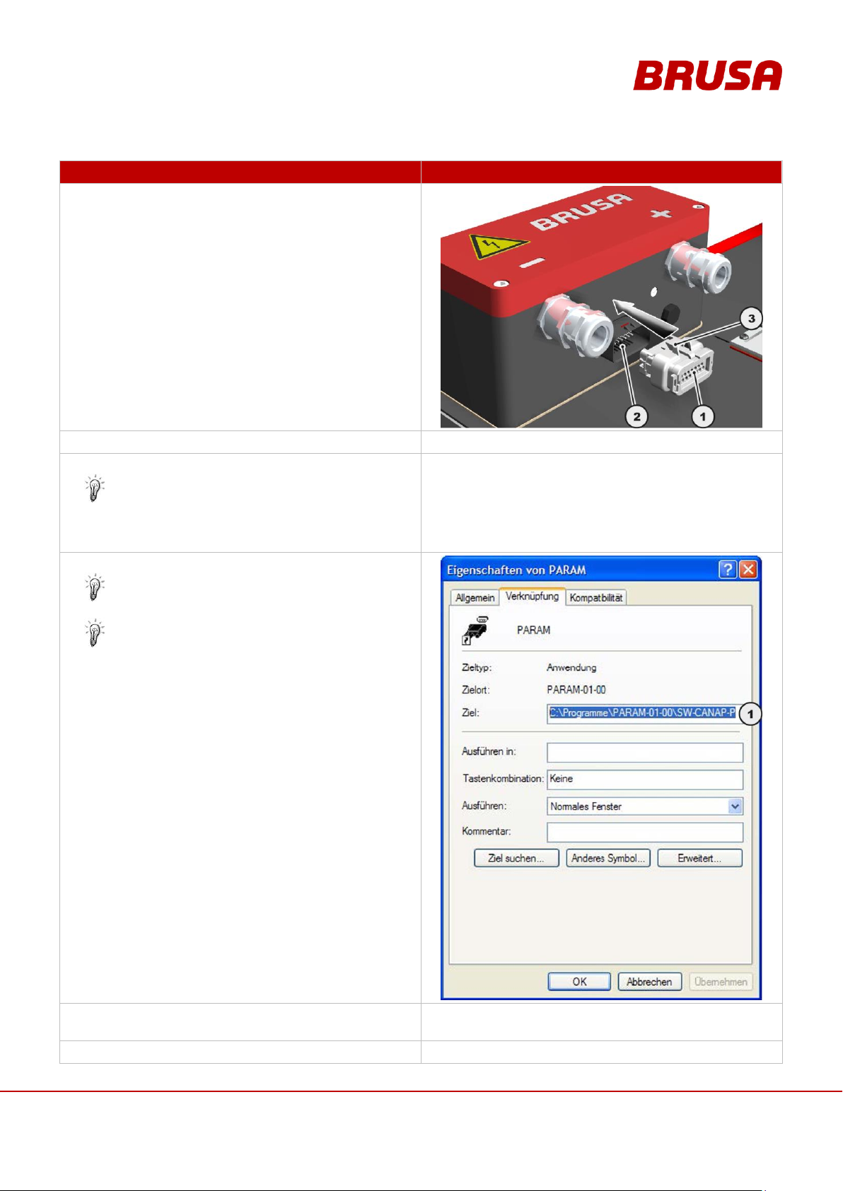
61
Technical data
and start-up
EVB1-350/400-40-HP
PROCEDURE STEP
ILLUSTRATION / OTHER INFORMATION
4.
Connect the control plug (1) to the female
connector (2) of the battery. Check the control plug
(1) for secure fit (locking (3) activated).
5.
Install the CAN dongle.
---
6.
Install the provided software PCANview.
This software is recommended by BRUSA.
Customer-specific software can of course be
used as an alternative for this.
---
7.
Install the provided software PARAM (PARAM.msi).
See the manual Bedienung_PARAM.pdf
Using properties check whether the shortcut
PARAM was installed on the right path (1). The
path (1) may need to be adapted to suit the
installation path.
8.
Start the software BMS_Monitor
(BMS_Monitor_D.exe).
---
9.
Switch terminal 30 to high.
---
Page 62
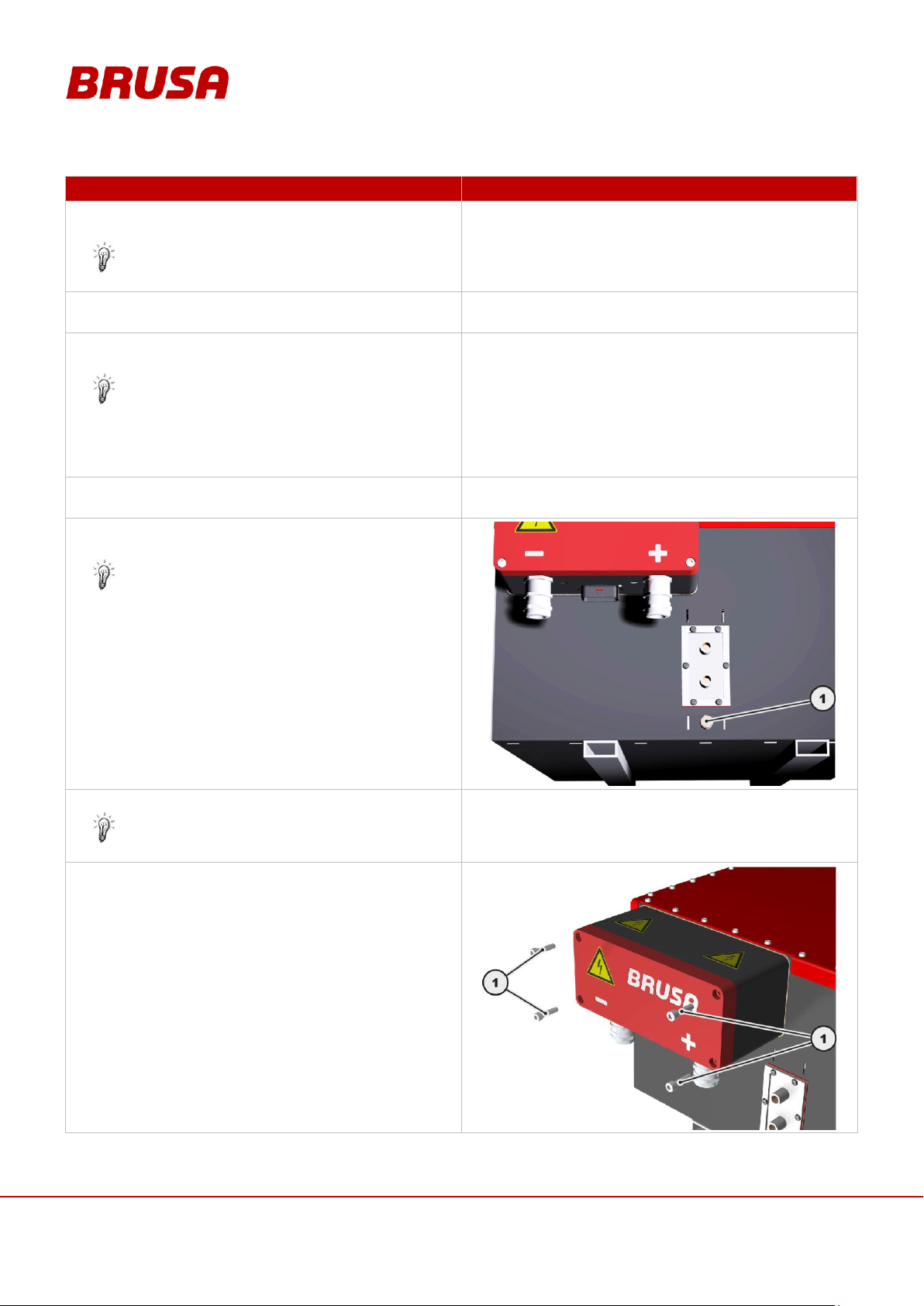
Technical data
and start-up
EVB1-350/400-40-HP
62
PROCEDURE STEP
ILLUSTRATION / OTHER INFORMATION
10.
Switch terminal 15 to high (e.g. switch on ignition key
in vehicle).
The BMS is switched on / activated.
---
11.
Check the status and the current battery data of the
BMS with the Param Software
---
12.
If all the battery data is OK, switch pin 15 to low (e.g.
switch off ignition key in vehicle).
If the battery data is not OK, there is a fault.
Should you have any questions, please contact
our support service at the manufacturer address
given in chapter 4.6.
---
13.
Pull the control plug out from the battery's female
connector (note the plug lock).
---
14.
Connect the ground cable to the grounding
screw (1).
Torque = 10 Nm
15.
Connect the HV supply.
See chapter 9.2 Building HV Supply
---
16.
Unscrew the screws (1).
Page 63
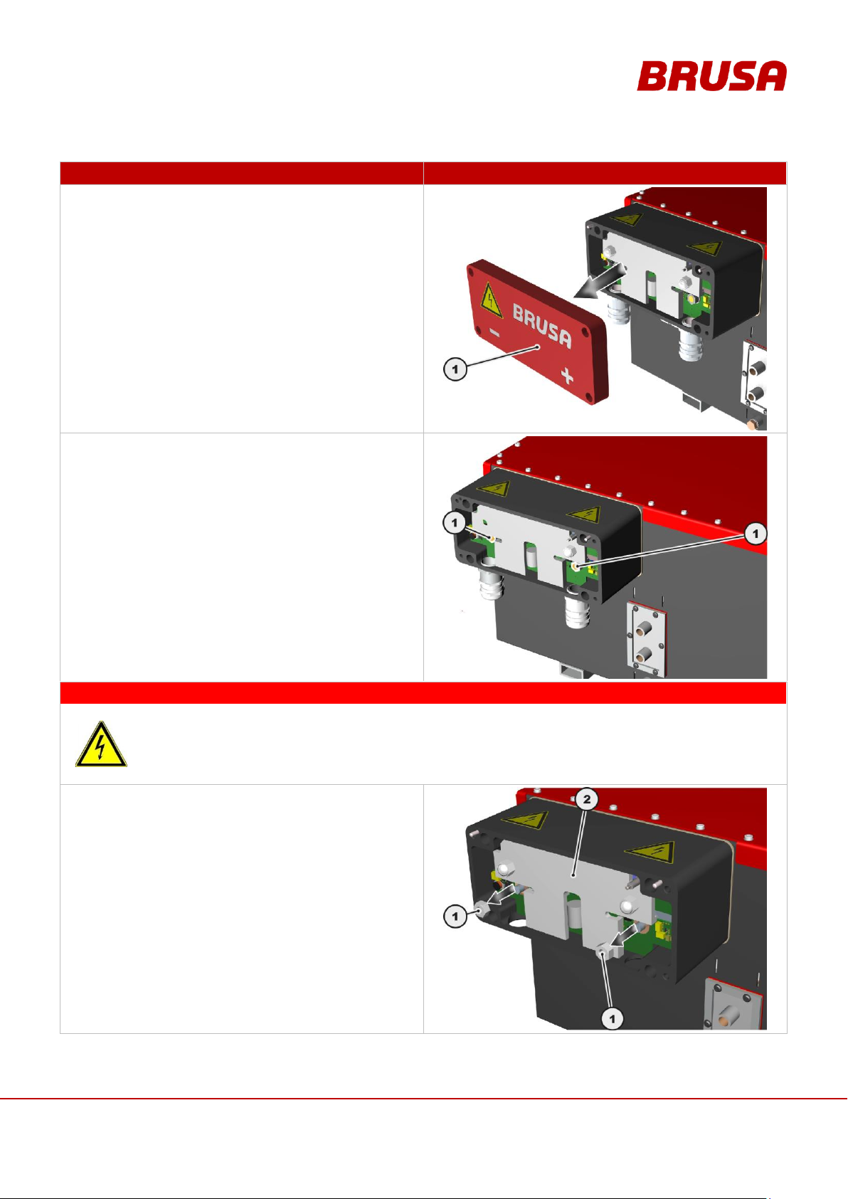
63
Technical data
and start-up
EVB1-350/400-40-HP
PROCEDURE STEP
ILLUSTRATION / OTHER INFORMATION
17.
Take the BMS covering (1) off.
18.
Ensure that the HV contacts (1) are not live using a
suitable multimeter.
DANGER
High voltage!
Danger to life!
The HV protector (2) is a safety installation and may under no circumstances be dismantled.
The HV protector (2) protects the operator from touching the HV contacts!
19.
Unscrew the M8 hexagonal nuts (1).
Page 64
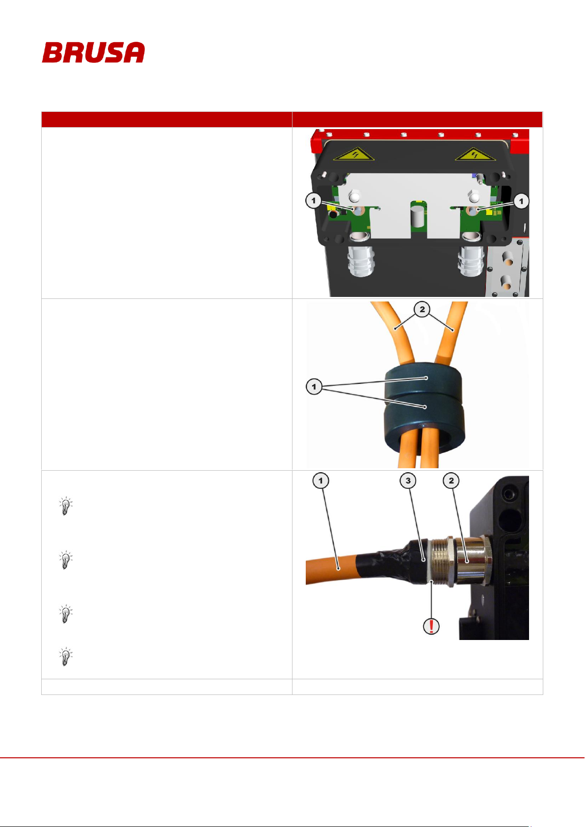
Technical data
and start-up
EVB1-350/400-40-HP
64
PROCEDURE STEP
ILLUSTRATION / OTHER INFORMATION
20.
Ensure that the washers (1) are positioned.
21.
Set the magnetic cores (1) one behind another on
the HV wiring (2).
22.
Lead the prepared HV cable (1) through the cable
gland (2) in the BMS.
You must ensure that the washers are
positioned on the HV contacts before you attach
the cable lugs! (See procedure step 20)
Check whether the terminal insert (3) fits closely
into the cable gland (2). Here the cable lug must
sit on the thread bolt.
How to modify the cable, you can see in chapter
9.2 Building HV Supply
23.
Remove the insulating tape from the terminal insert.
---
Page 65
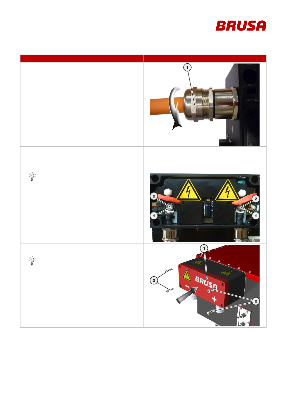
65
Technical data
and start-up
EVB1-350/400-40-HP
PROCEDURE STEP
ILLUSTRATION / OTHER INFORMATION
24.
Position the union nut (1) manually.
25.
Repeat procedure steps 22-24 on the second HV
cable.
---
26.
Position the M8 hexagonal nuts (1) on the HV
connections (2) and tighten them.
Torque = 5 Nm
27.
Position the BMS covering (1) and tighten the
screws (2).
Torque = 10 Nm
Page 66
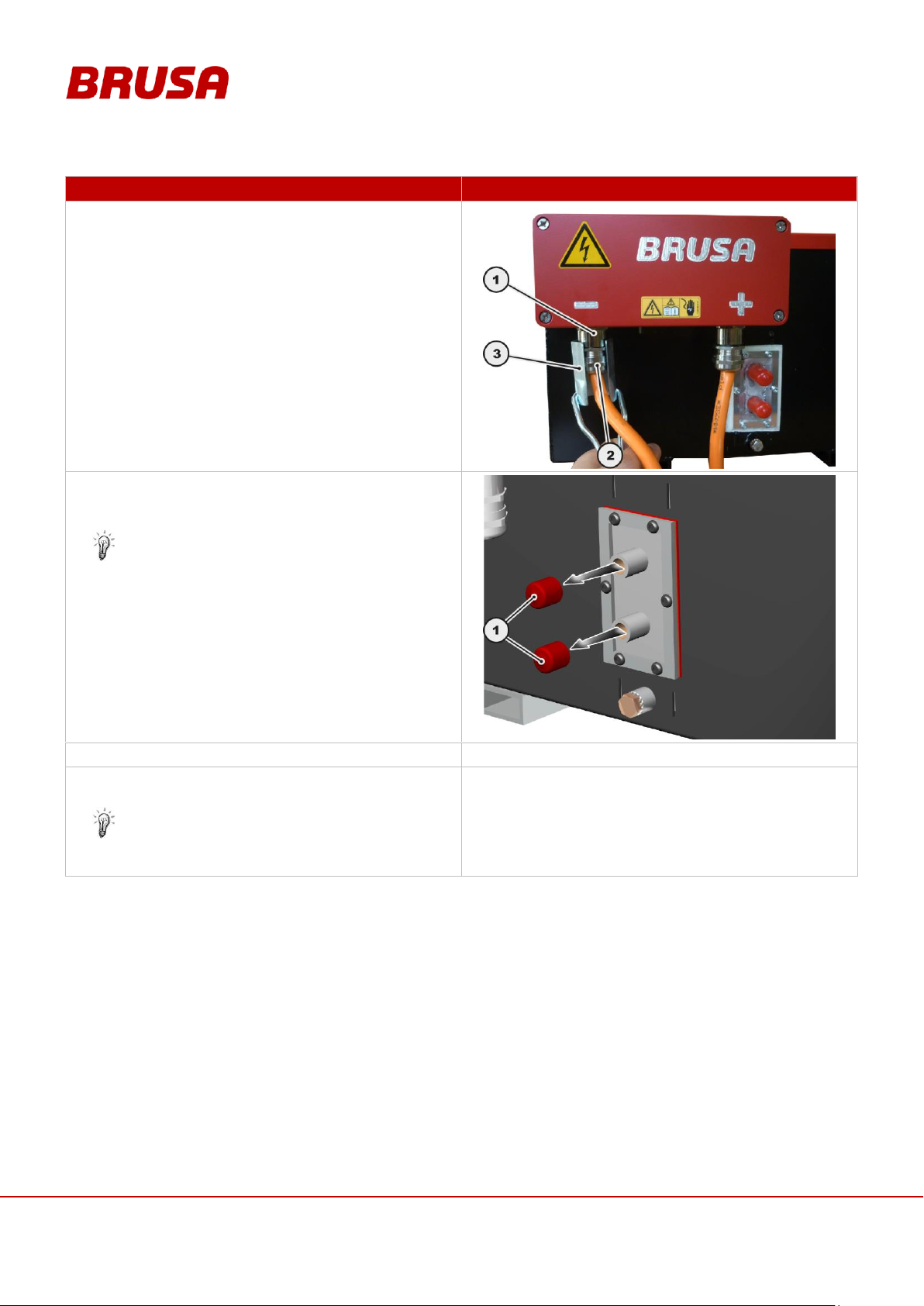
Technical data
and start-up
EVB1-350/400-40-HP
66
PROCEDURE STEP
ILLUSTRATION / OTHER INFORMATION
28.
Tighten the cable glands (1) and the union nuts (2)
with the special key (3).
29.
Remove the protective caps for the cooling water
connection pieces (1) and connect the cooling water
pumps with the hose clips.
See chapter 7.1 Circuit Connections
30.
Start the software PARAM.
---
31.
Check the set parameters with the software PARAM
or adapt these to your requirements.
See chapter10.3 Changing the CAN Parameters
with PARAM
---
Page 67
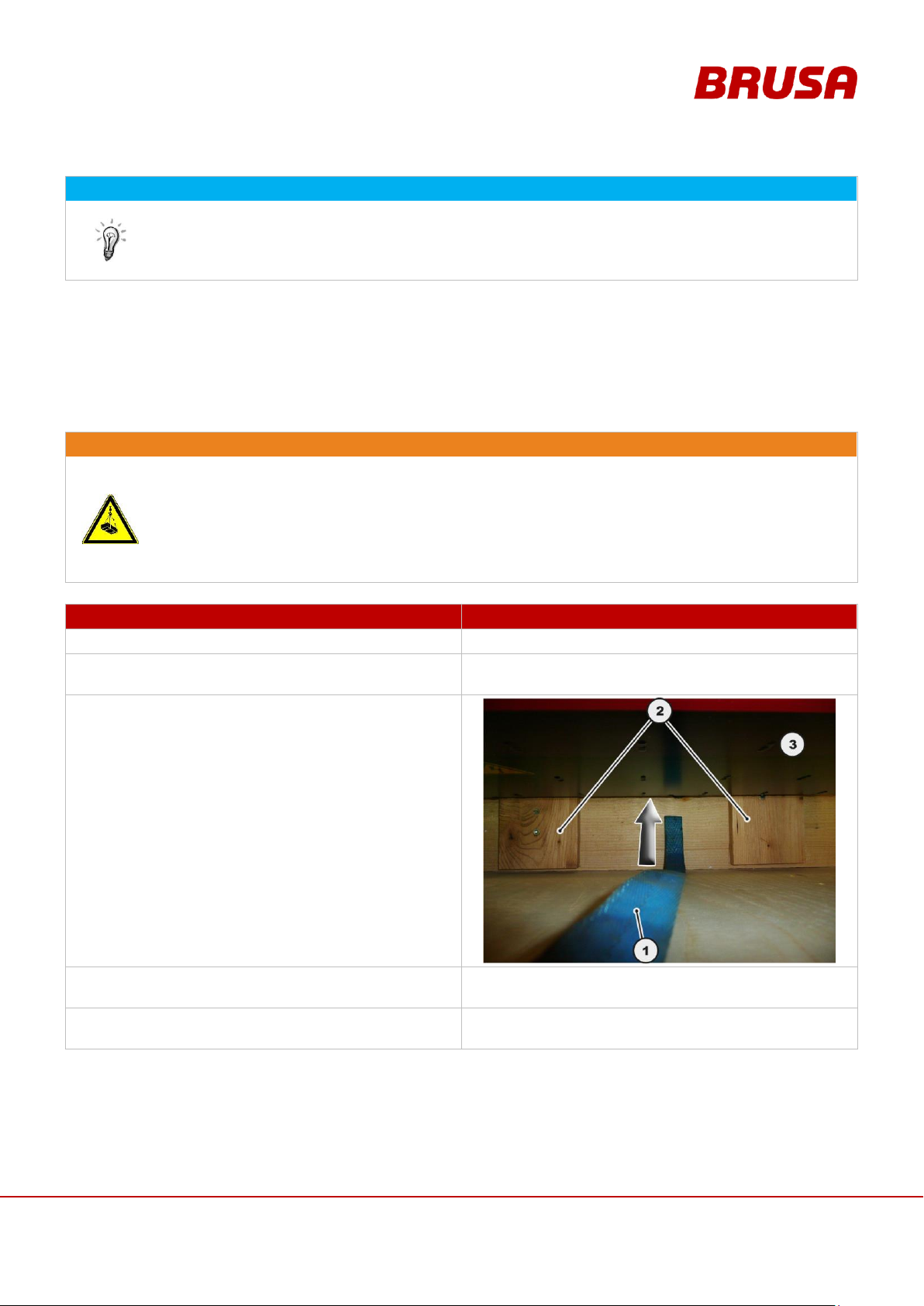
67
Technical data
and start-up
EVB1-350/400-40-HP
INFORMATION
The battery is now ready for operation and can be driven via terminal 15 or via the CAN,
see chapter 6.9 Regulation and Control System
The switching on of the battery (switching of the main contactors during pre-charging) is very easily
heard and can therefore be used as a monitor.
WARNING
Suspended load!
Crushing danger!
When lifting the battery out of the transportation box it can fall if the lifting device slips or if the crane
is operated in the wrong way!
Never go underneath the battery!
Observe the loading limits when choosing a lifting device (145 kg net-weight battery)!
PROCEDURE STEP
ILLUSTRATION / OTHER INFORMATION
1.
Remove the lid of the transportation box.
---
2.
Remove the air bag and other packaging materials
from the transportation box.
---
3.
Lead a tension belt (1) suitable for this weight
between the wooden planks (2) under the
battery (3).
4.
Lead a second tension belt under the battery along
with this.
---
5.
Position a suitable hoisting device (e.g. forklift) over
the centre of the battery.
---
9.1 Unpacking the Battery
Page 68
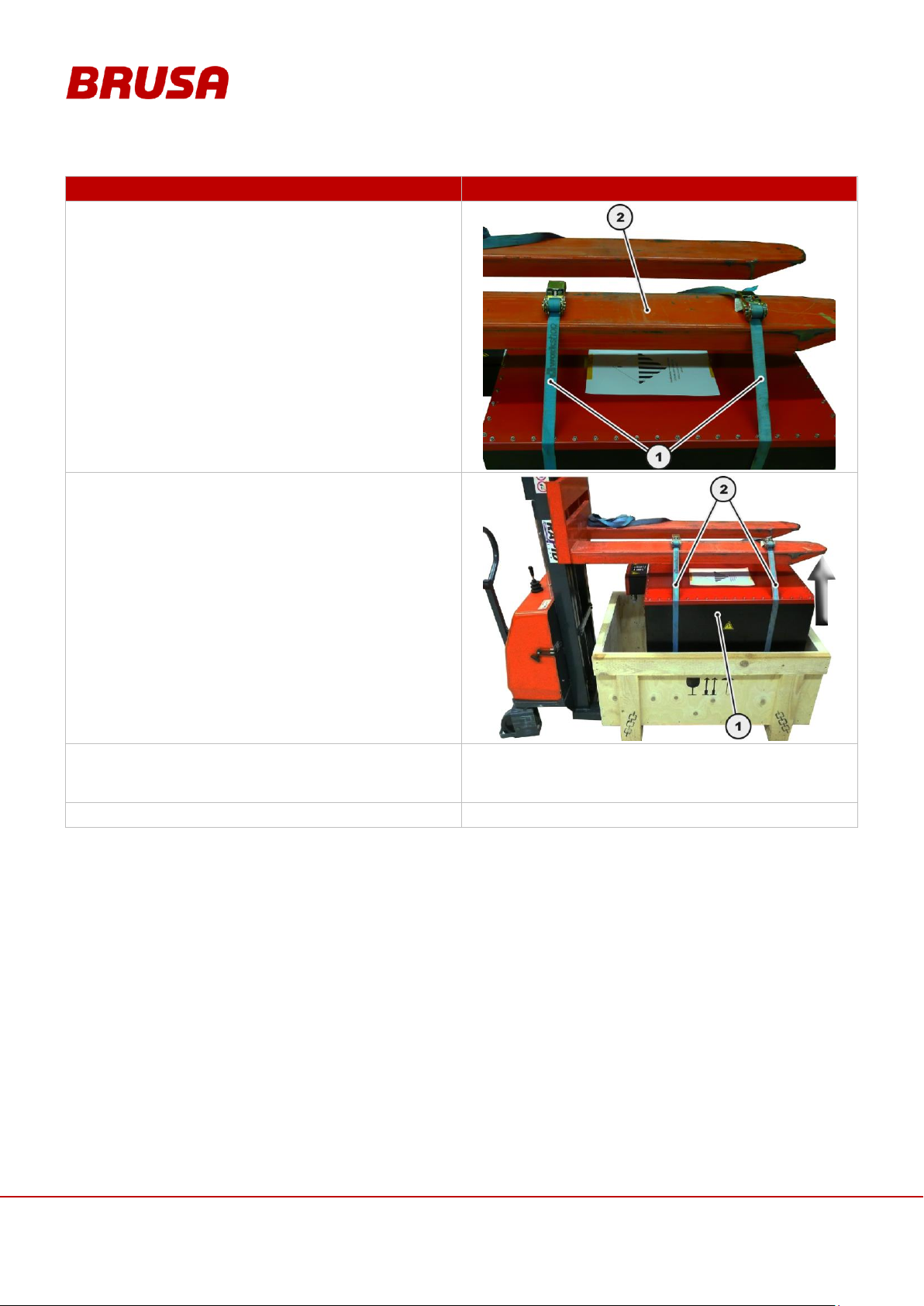
Technical data
and start-up
EVB1-350/400-40-HP
68
PROCEDURE STEP
ILLUSTRATION / OTHER INFORMATION
6.
Connect both tension belts (1) evenly with the
hoisting device (2).
7.
Hoist the battery (1) carefully by around 20 cm and
check the secure position of both tension belts (2).
8.
Hoist the battery out of the transportation box
carefully and place the battery down on a secure and
even surface.
---
9.
Remove the tension belts.
---
Page 69
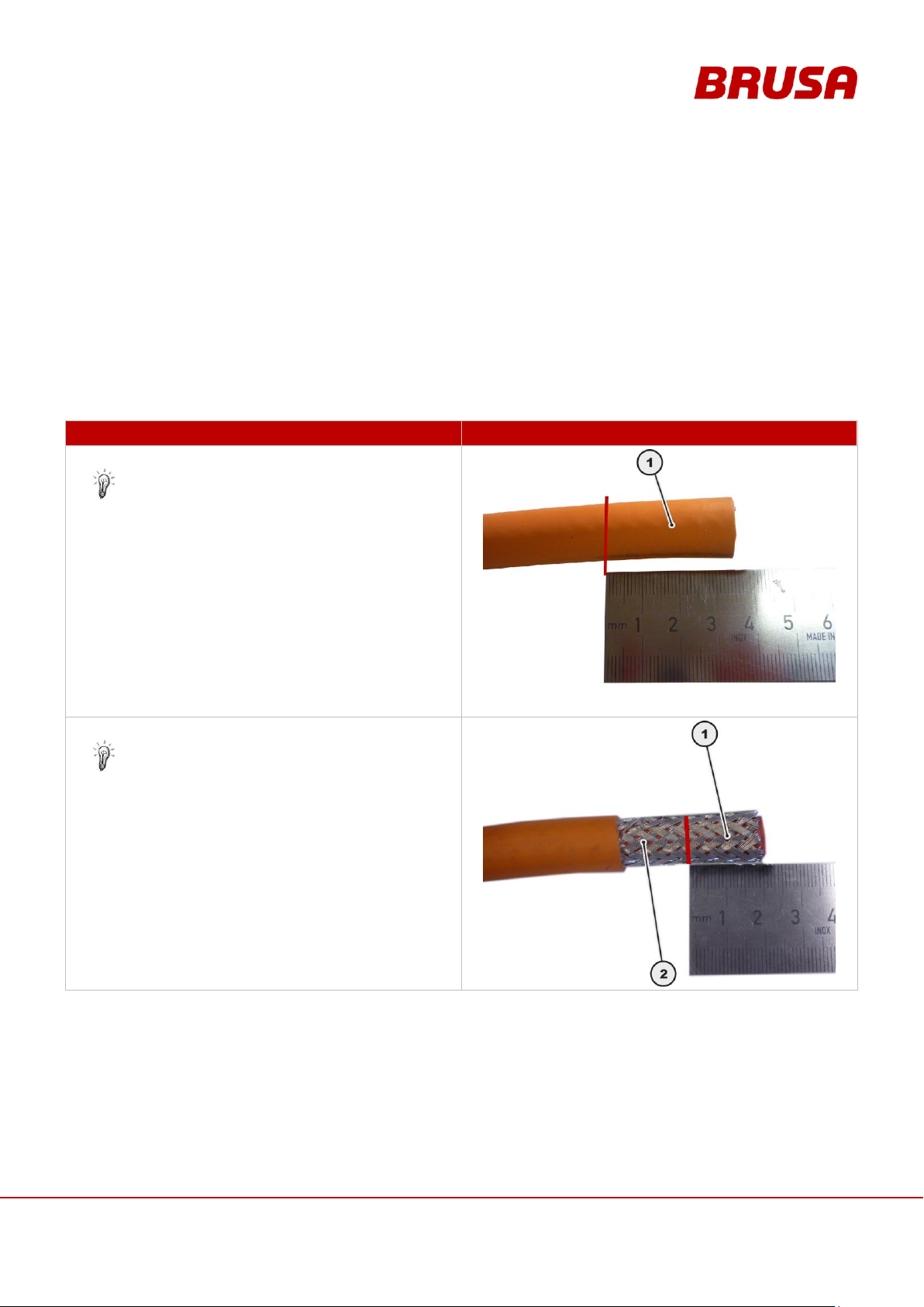
69
Technical data
and start-up
EVB1-350/400-40-HP
9.2 Building HV Supply
PROCEDURE STEP
ILLUSTRATION / OTHER INFORMATION
1.
Insulate 35 mm of the HV cable (1).
Ensure that you do not damage the shielding
braid underneath it!
2.
Shorten the shielding braid (1) by 20 mm.
The cable-side shielding braid (2) must be a
length of around 15 mm.
The building of the HV wiring must be carried out in accordance with the following instructions. Here it is important
that no strands are damaged and that none stick out at the sides on the assembled cable. So check that the screw
connections are correct for each completed cable and that the cable lug is fixed properly (pull test).
For the HV connections we recommend:
A shielded, insulated automotive cable (e.g. Huber & Suhner).
Cable lug, for the type see chapter 4.3 Delivery Contents
To assemble the cable lugs, using the appropriate crimping tool is absolutely necessary!
Page 70
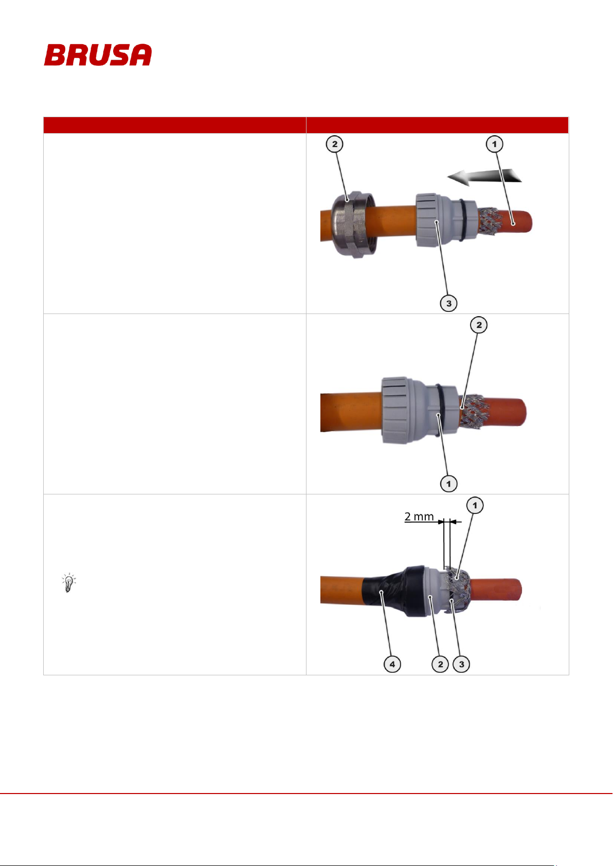
Technical data
and start-up
EVB1-350/400-40-HP
70
PROCEDURE STEP
ILLUSTRATION / OTHER INFORMATION
3.
Lead the HV cable (1) through the union nut (2).
Lead the HV cable (1) through the terminal insert (3).
4.
Place the terminal insert (1) with the front edge flush
with the cable insulation (2).
5.
Put the shielding braid (1) over the terminal
insert (2).
During this, the shielding braid (1) may overlap the
O-Ring (3) by a maximum of 2 mm.
Fix the terminal insert (2) in position on the HV
cable, eg with electrical tape (4).
You must absolutely make sure that the
individual strands of the shielding braid (1) do
not jut out over the sealing ring (3) under any
circumstances! Once in the integrated state, this
will lead to leakages and subsequently to the
leaking of water into the BMS!
Page 71
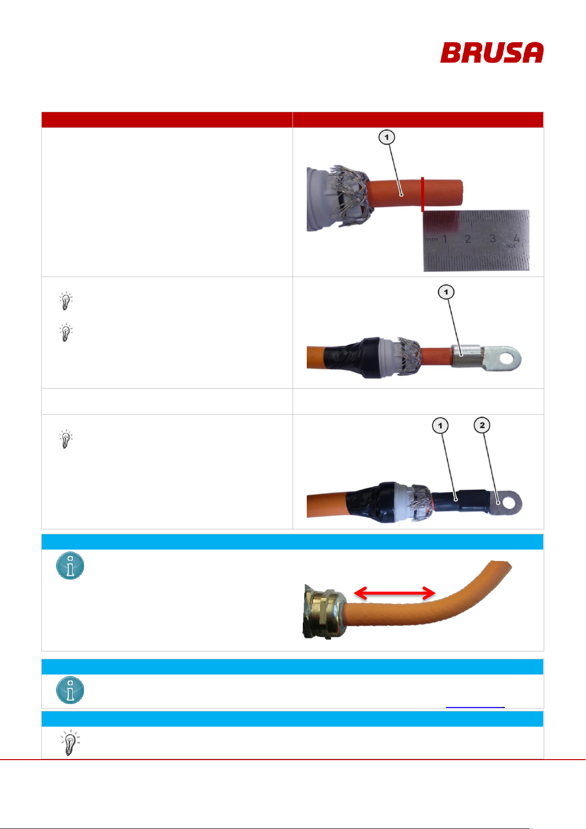
71
Technical data
and start-up
EVB1-350/400-40-HP
PROCEDURE STEP
ILLUSTRATION / OTHER INFORMATION
6.
Insulate 16 mm of the HV cable (1).
7.
Assemble the cable lug (1) at the end of the cable.
No strands should stick out at the sides!
The crimping must be hexagonal. Ensure that
the crimping has no deformations at the sides
because this will make later installations in the
BMS housing difficult!
8.
Check the secure positioning of the cable lug
manually.
---
9.
Assemble a shrinkage tube (1) on the cable lug (2).
The assembly of a shrinkage tube (1) is
absolutely necessary because otherwise
contacting can result in the BMS housing!
INSTRUCTION
During the layout of the cable take care that
the first part of the cable is at least 5cm
straight before it will be bend to a radius.
INSTRUCTION
If you have to reassembly the cable you have to use a new terminal insert. Otherwise it can cause a
leakage.
The terminal inserts can be ordered from BRUSA Elektronik AG or directly from hummel.com.
NFORMATION
The HV cable is now ready and can be connected to the BMS. Repeat the process with the second
HV cable.
5cm
Page 72
Technical data
and start-up
EVB1-350/400-40-HP
72
INSTRUCTION
Air pockets in the cooling passage along with generally insufficient cooling of the battery lead to
increased wear!
Ensure that the cooling circuit is always fault-free.
The cooling water must always be actively cooled to ensure the optimum operating temperature. The
temperature of the cooling water should not surpass +20°C. At temperatures higher than this, the
coolant to battery Delta-T does not reach high enough a level to have a cooling effect!
You can find several profiles on the effect of the cooling water temperature on the battery
temperature in chapter 8.3 Temperature / Cooling System .
PROCEDURE STEP
ILLUSTRATION / OTHER INFORMATION
1.
Check the secure fixing of the cooling water
connections to the battery.
---
2.
Switch on the cooling circuit.
---
3.
Leave the cooling circuit on for around 30 s.
---
4.
Switch off the cooling circuit.
---
5.
Check the cooling water level.
---
INFORMATION
All CAN applications are based on the CAN hardware of PEAK System
(www.peak-system.com). For the CAN communication we recommend the use of optically decoupled
USB adapters along with the compatible 120 ohm terminating resistor:
IPEH-002022 (PCAN USB adapter)
IPEK-003003 (PCAN terminating resistor)
You can obtain the installation files along with corresponding installation guidelines directly by
downloading them from the homepage of the manufacturer.
9.3 Ventilating the Cooling System
9.4 Installing the CAN Dongle
Page 73
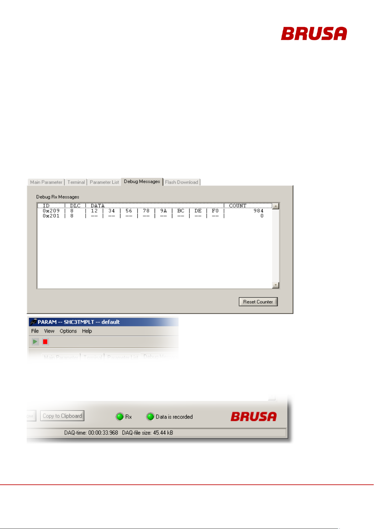
73
Technical data
and start-up
EVB1-350/400-40-HP
10 Operation
The Debug Messages Tab lists all registered CAN messages. They are listed in the XML file. The view can be
used to see if all expected messages are on the bus. The PARAM tool can save a log file (MDF-format) of all
registered messages.
Press on the green start button to start the data
acquisition. Select a filename and press Save. The
filename will be ap-pended by a date string. You‟ll see in
the status area if the DAQ is running. The status bar
shows the duration of the DAQ and the file size written so
far. Press the stop button to terminate the data logging. It
is very important to stop the logging prior copying or opening the file. If you try to open a non-terminated file the
data may be lost. MDF files can be opened with the CANgraph from Vector Informatik GmbH.
10.1 Reading CAN Parameters
10.1.1 Debug Messages – Data Logging with PARAM
Page 74
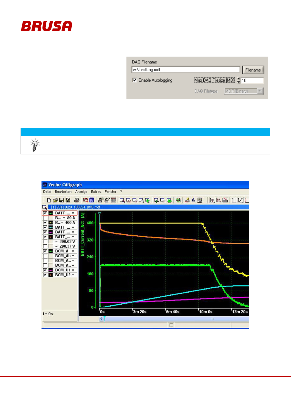
Technical data
and start-up
EVB1-350/400-40-HP
74
You can enable auto logging in the Setup
dialog. This will automatically start DAQ
whenever the PARAM tool is started. The
logging will start a new file when the given
Max DAQ file size is reached. A date string is
added to the filename.
INFORMATION
For the reading / analysis of *.mdf files we recommend the software CANgraph by Vector
(www.vector.com). The analysis can of course be carried out through other customer-specific
software.
10.1.2 Analysing Battery Data
The following graph shows as an example the possible representation of the recorded data from the software
PARAM. This representation differs depending on the software used!
Page 75
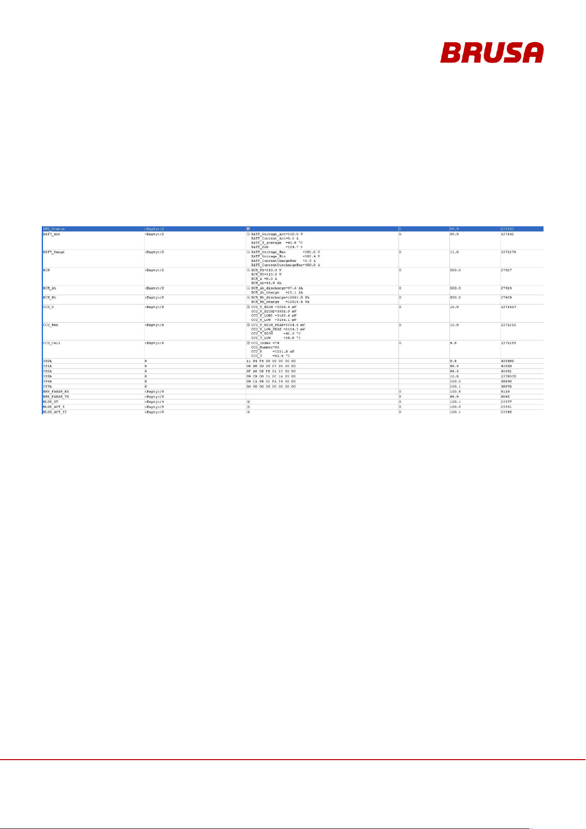
75
Technical data
and start-up
EVB1-350/400-40-HP
10.2 Live View of the Battery Data
With the corresponding software the battery data can be viewed in real time. For this we recommend for example
the software PCAN-Explorer or PCANView. To be able to view the battery data, you must import the included file
BMS_CAN1.dbc into the software you are using. Any battery data from CAN1 will then be displayed in table form.
The following graph shows as an example the possible representation from the software PCAN-Explorer. This
representation differs depending on the software used!
Page 76
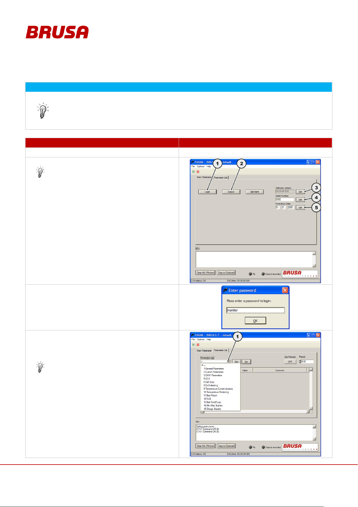
Technical data
and start-up
EVB1-350/400-40-HP
76
INFORMATION
The installation of PARAM takes place in the course of the initial start-up, see chapter 9 Installation /
Initial Start-up
With the software PARAM all parameters can be viewed. There is the possibility of adapting
individual parameters specifically. You can find a listing of the configurable parameters as well as a
description of them in chapter 10.3.1Configurable Parameters
PROCEDURE STEP
ILLUSTRATION / OTHER INFORMATION
1.
Start the software PARAM.
---
2.
Press the Login button (1).
In this dialogue box you can see the software
version, serial number and the date of
manufacture of the battery if need be.
(1) Login button
(2) Logout button
(3) Reading of the software version
(4) Reading of the serial number
(5) Reading of the date of manufacture
3.
Enter the password monitor.
Confirm the entry with OK.
4.
After a successful login you will then have the
possibility of viewing all parameters and adapting
them individually.
To do this click on the drop down list (1).
You can find a listing of the configurable
parameters as well as a description of them in
chapter 10.3.1 Configurable Parameters
10.3 Changing the CAN Parameters with PARAM
Page 77
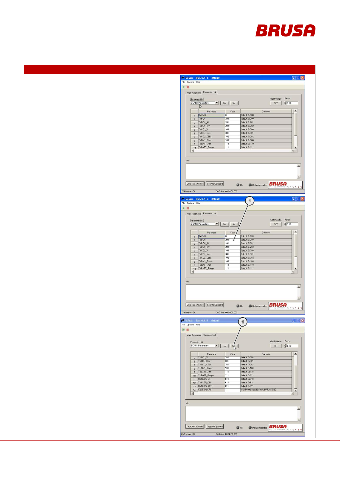
77
Technical data
and start-up
EVB1-350/400-40-HP
PROCEDURE STEP
ILLUSTRATION / OTHER INFORMATION
5.
Select the desired tab (here tab 3).
6.
Change the desired parameters by typing in the
column value (1).
7.
To accept the changed data in the BMS, click the
button Set (1).
Page 78
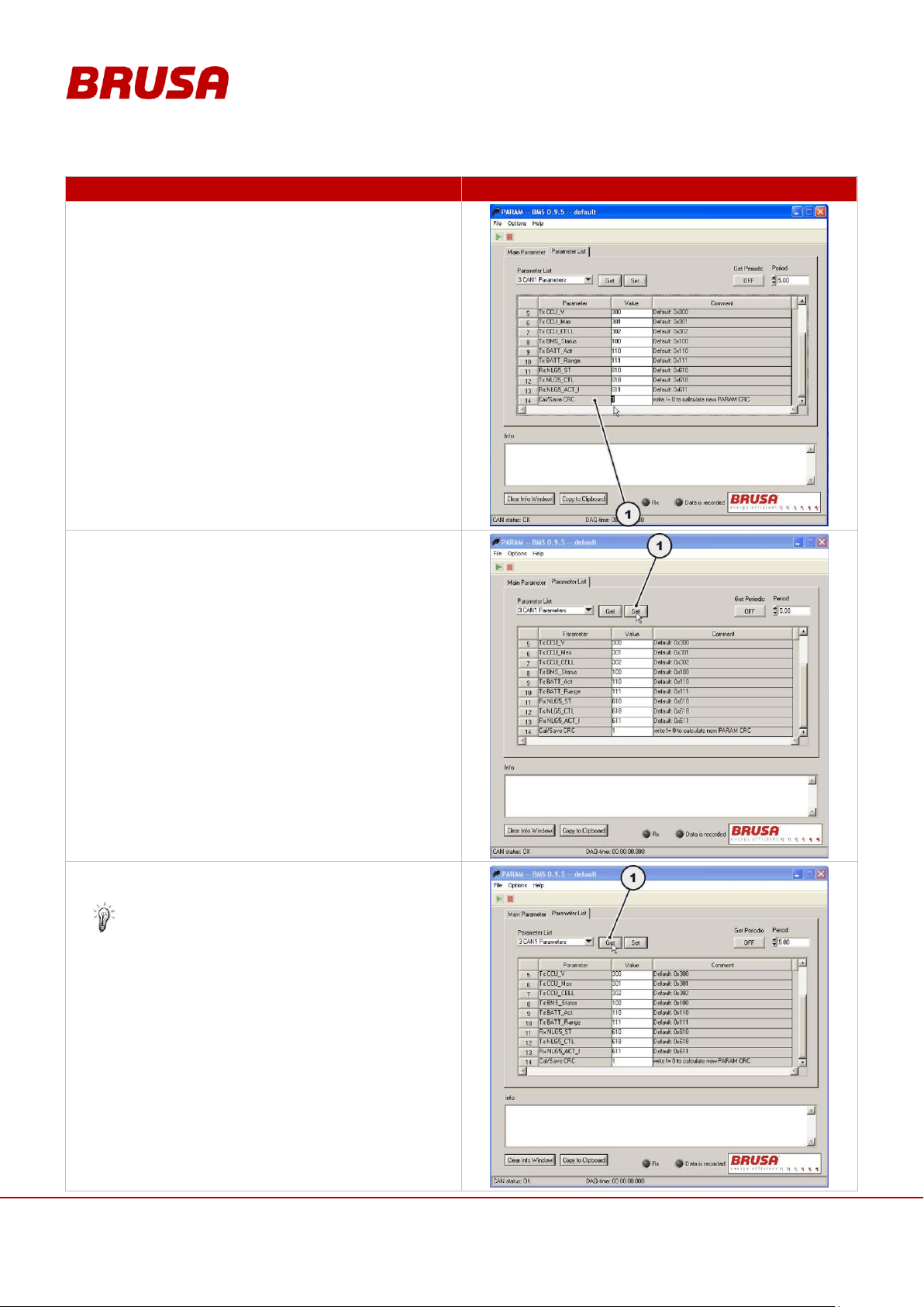
Technical data
and start-up
EVB1-350/400-40-HP
78
PROCEDURE STEP
ILLUSTRATION / OTHER INFORMATION
8.
To save the changed values, scroll down to the
bottom line Cal/Save CRC (1) and enter the value 1
in the column value.
9.
To accept the changed data in the BMS, click the
button Set (1) again.
10.
Click the button Get (1) to check whether the
changed values have been saved in the system.
After clicking the button Get (1) check the values
in the column value.
Page 79
79
Technical data
and start-up
EVB1-350/400-40-HP
PROCEDURE STEP
ILLUSTRATION / OTHER INFORMATION
11.
After successful configuration, end the software
PARAM.
---
INFORMATION
To save the changed configuration the following steps must be carried out:
12.
Carry out a reset at terminal 15 (switched positive).
---
13.
Carry out a reset at terminal 30 (permanent positive).
---
INFORMATION
The changed parameters are now saved in the battery. The battery can now be connected and
operated again.
Page 80
Technical data
and start-up
EVB1-350/400-40-HP
80
INFORMATION
In this chapter, only the configurable parameters are listed. The complete CAN matrix is a part of the
customer package.
1 GENERAL PARAMETERS
NO.
NAME
INIT
DESCRIPTION
1.4
DBG COM Master ID
0x400
ID of battery Tx message
1.5
DBG COM Slave ID
0x401
ID of battery Tx message
3 CAN1 PARAMETERS
NO.
NAME
INIT
DESCRIPTION
3.1
Rx CMD
0x000
ID of message
0 = no function
BMS is switched on via terminal 15
3.2
Tx BCM
0x200
ID of message
0 = not sent
3.3
Tx BCM_Ah
0x201
ID of message
0 = not sent
3.4
Tx BCM_Wh
0x202
ID of message
0 = not sent
3.5
Tx CCU_V
0x300
ID of message
0 = not sent
3.6
Tx CCU_Max
0x301
ID of message
0 = not sent
3.7
Tx CCU_CELL
0x302
ID of message
0 = not sent
3.8
Tx BMS_Status
0x100
ID of message
0 = not sent
3.9
Tx BATT_Act
0x110
ID of message
0 = not sent
3.10
Tx BATT_Range
0x111
ID of message
0 = not sent
3.11
Rx NLG5_ST
0x610
ID of message NLG5_ST
0 = not sent
3.12
Tx NLG5_CTL
0x618
ID of message NLG5_CTL
0 = not sent
3.13
Rx NLG5_ACT_I
0x611
ID of message NLG5_ACT_I
0 = not sent
3.14
Baud rate
500 (1000)
---
3.15
Sampling point
68.75
---
12 NLG
NO.
NAME
INIT
DESCRIPTION
12.1
Mains: max. current
16.0 A
Max. current from the 240 V AC network
12.2
Phase1: C-rate
0.5 C
Max. charging current of phase 1
12.3
Phase1: max. cell voltage
4.15 V
Max. cell voltage of phase 1
12.4
Phase1: cut-off current
2.0 A
Switch to phase 2 as soon as the current has fallen below this level
12.5
Phase2: max. current
2.0 A
Max. charging current of phase 2
12.6
Phase2: max. Ah
0.5 Ah
Max. charging in phase 2
12.7
Phase2: max. time
180.0 min
Max. charging time of phase 2
10.3.1 Configurable Parameters
Page 81

81
Technical data
and start-up
EVB1-350/400-40-HP
12 NLG
NO.
NAME
INIT
DESCRIPTION
12.8
Balancing
0.10 V
Max. cell voltage difference
(Max Cell Voltage – V_diff = V_min)
13 FAN&PUMP
NO.
NAME
INIT
DESCRIPTION
13.1
Step1: temp off
25°C
Step 1 switch-off temperature
13.2
Step1: temp on
30°C
Step 1 switch-on-temperature
13.3
Step1: fan
50%
Step 1 fan power in percent
The fan power depends on the input voltage at pin 2 AUX
13.4
Step1: ext. fan
50%
Step 1 external fan power in percent
13.5
Step1: pump
99%
Step 1 external water pump power in percent
13.6
Step2: temp off
30°C
Step 2 switch-off temperature
13.7
Step2: temp on
35°C
Step 2 switch-on temperature
13.8
Step2: fan
99%
Step 2 fan power in percent
The fan power depends on the input voltage at pin 3 EN
13.9
Step2: ext. fan
99%
Step 2 external fan power in percent
13.10
Step2: pump
99%
Step 2 external water pump power in percent
Page 82
Technical data
and start-up
EVB1-350/400-40-HP
82
INFORMATION
The following chapters are only relevant for the use of the battery EVB1 in combination with the
BRUSA NLG513 charger. If you are using another charger then you can obtain this information from
the manufacturer.
10.4 Charging with the NLG513 Charger
10.4.1 Charging via the CAN
In order to drive the charge process via the CAN, the battery control plug and the charger must be completely wired
up. Furthermore, the NLG513 charger must be parameterised in such a way as to enable communication with the
battery. Parameter setting is carried out via the software ChargeStar, which is included in the delivery content of
the NLG513 charger.
The CAN parameters necessary for charging are included in the customer package. The CAN parameters must be
loaded into the software ChargeStar. After the CAN parameters have been successfully loaded, the CAN
communication between the battery and the charger must be established.
As soon as the mains plug is connected, the charger starts and regulates the charging process independently
using the uploaded CAN parameters.
You can find detailed information on this in the NLG513 charger manual.
Page 83
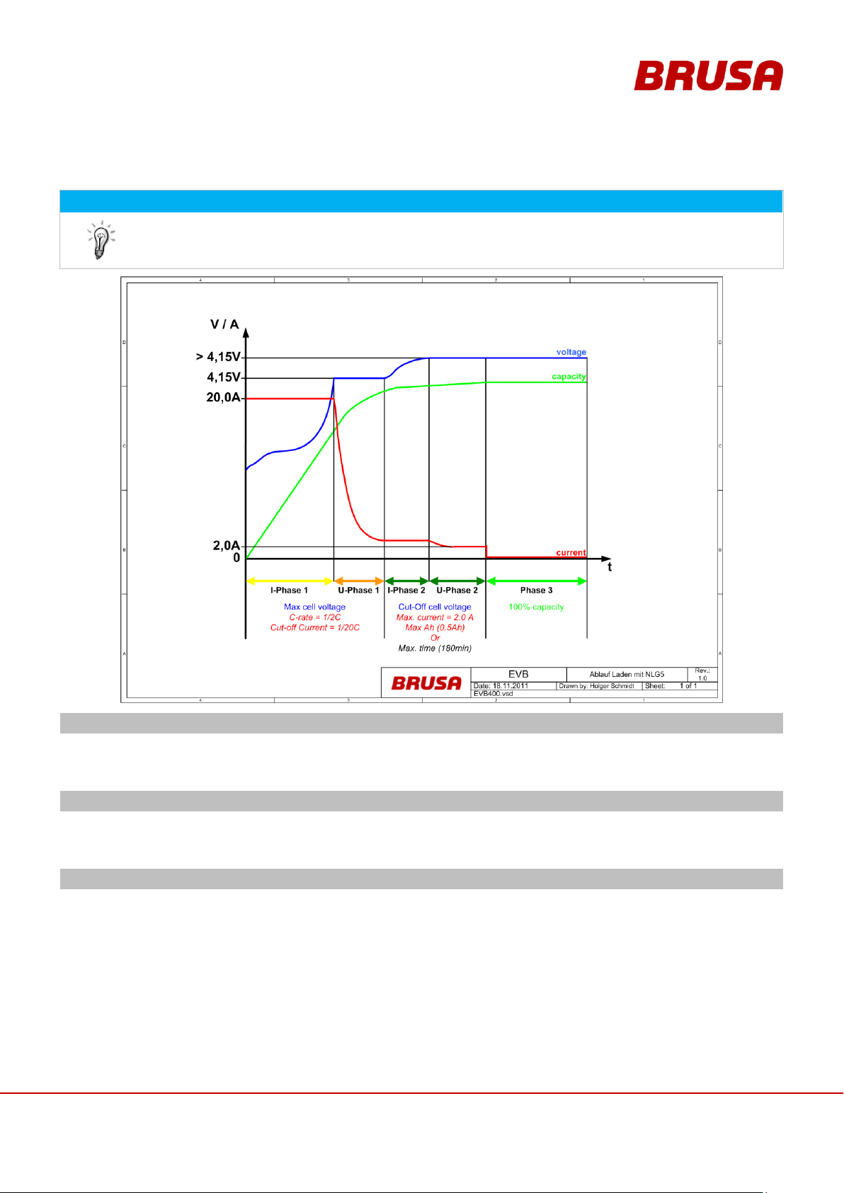
83
Technical data
and start-up
EVB1-350/400-40-HP
10.4.2 Course of a Charging Process
INFORMATION
By using the BRUSA NLG513 charger, along with being able to control via the CAN, you can also
programme charging profiles using the software ChargeStar.
The following charging profile provides an example of this.
Phase 1 (I1 and U1)
The charging process begins in this phase with constant current (if voltage < U1 and the charger provides this
current). The transition into phase U1 takes place when the defined voltage U1 is reached. Now the voltage is
held constantly at U1 by reducing the charging current. This stage is referred to as Main Charging.
Phase 2 (I2 and U2)
The transition into stage 2 can take place as early as phase I1 or U1 due to one or more conditions. In stage 2
the voltage level U2 is usually larger and the current level I2 is usually smaller than in stage 1. This stage is
referred to as Equalisation Charge.
Phase 3
The switch to stage 3 then takes place when certain requirements are fulfilled. In stage 3 both the voltage
level U3 and the current level I3 are usually smaller than in stage 1. Stage 3 is referred to as Trickle Charging.
Page 84
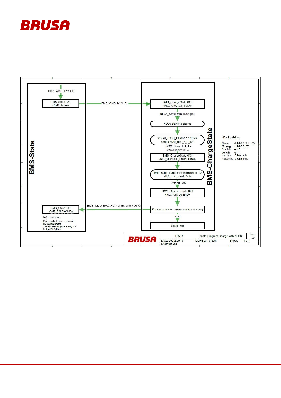
Technical data
and start-up
EVB1-350/400-40-HP
84
10.5 Charging with the NLG664 Charger
The charging with the NLG664 is described in following state-diagram:
Page 85
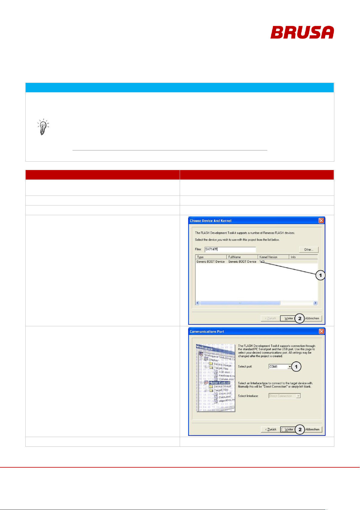
85
Technical data
and start-up
EVB1-350/400-40-HP
10.6 Carrying Out Firmware Updates
INFORMATION
The following requirements are necessary for the programming of the firmware:
PC with Win2000, Win XP or Win 7 operating system
RS232 interface
RS232 connection cable (PC to EVB1 control plug)
Switch on RS232 connection cable control plug (PIN 13 PRO)
Software FDT Flash Development ToolKit 4.00
http://eu.renesas.com/media/products/tools/eu_download/fdtv400r02.exe
Current firmware as a .mot file
PROCEDURE STEP
ILLUSTRATION / OTHER INFORMATION
1.
Connect the battery with your PC using the RS232
connection cable.
---
2.
Switch terminal 30 to high.
---
3.
Start the software FDT Flash Development ToolKit.
---
4.
Choose the setting Generic BOOT Device (1). Press
the Further button (2).
5.
Choose the port COM1 (1). Press the Further button
(2).
6.
Switch pin 13 PRO to high.
---
Page 86
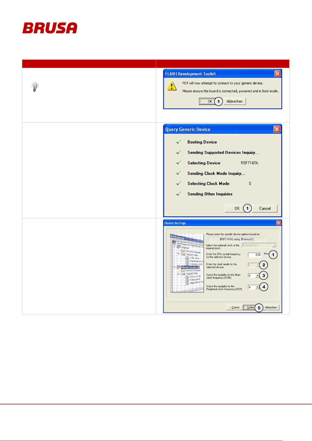
Technical data
and start-up
EVB1-350/400-40-HP
86
PROCEDURE STEP
ILLUSTRATION / OTHER INFORMATION
7.
Check the instructions in the dialogue box which
appears. Press the OK button (1).
The battery is now in Boot Mode. The querying
of the standard battery settings starts. After Boot
Mode is ended, the automatic reset of the
battery is activated. With this, the battery is
ready for operation immediately afterwards.
8.
Press the OK button (1).
9.
Set the CPU Frequency value (1) to 8.00 MHz.
Set the Clock Mode value (2) to 0.
Set the CKM value (3) to 8.
Set the CKP value (4) to 4.
Press the Further button (5).
Page 87
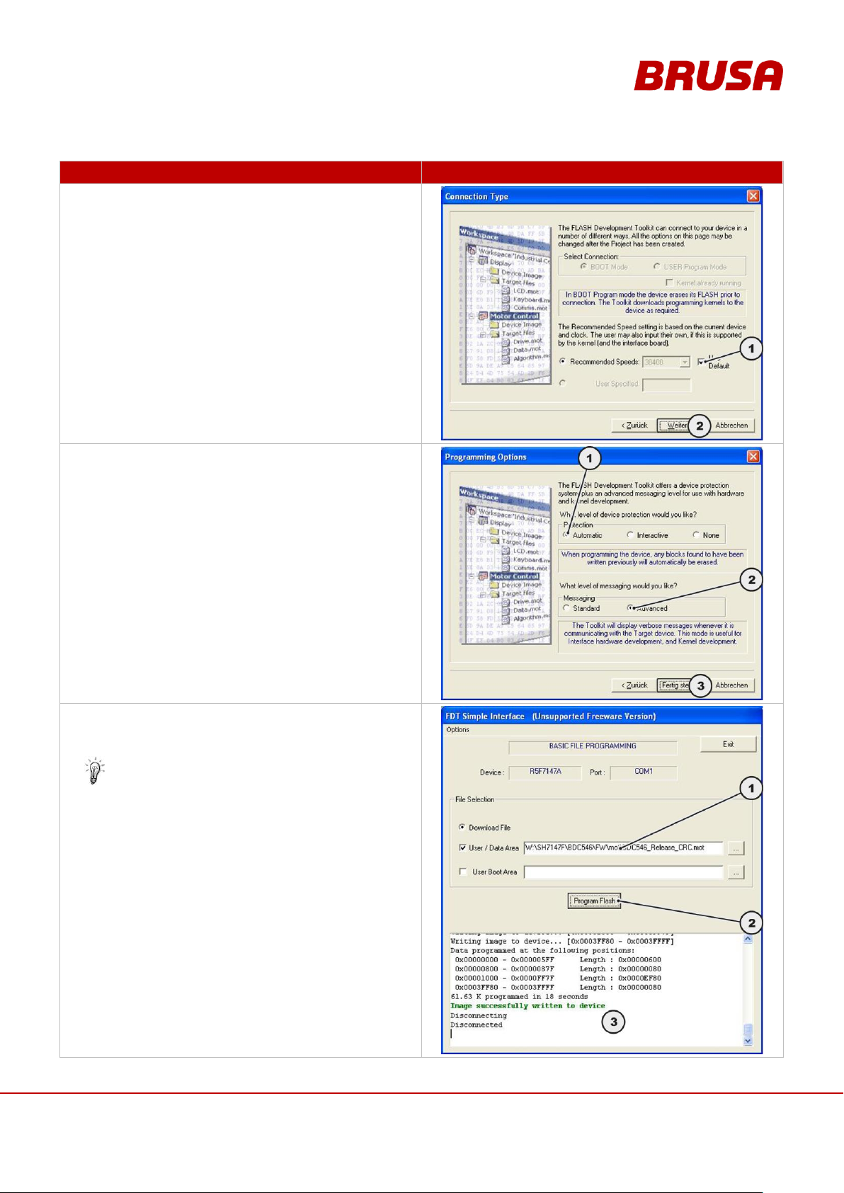
87
Technical data
and start-up
EVB1-350/400-40-HP
PROCEDURE STEP
ILLUSTRATION / OTHER INFORMATION
10.
Place the tick in the field use default (1). Press the
Further button (2).
11.
For Device Protection choose the Automatic setting
(1). For Messaging choose the Advanced setting (2).
Press the Finish button (3).
12.
Choose the place to save your new firmware (.mot
file) in the File selection – User/Data Area (1). Press
the Program Flash button (2).
The installation of the new firmware starts now.
On successful installation the message Image
successfully written to device appears in the
field (3).
Page 88
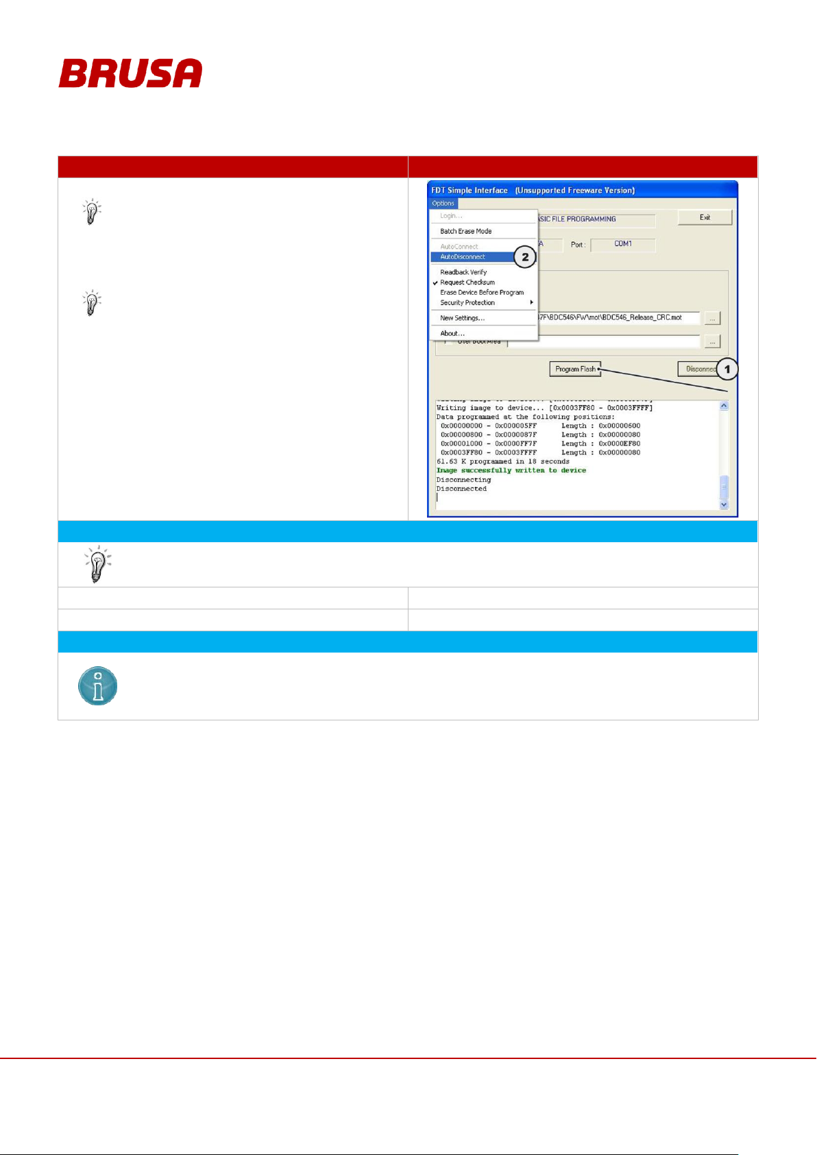
Technical data
and start-up
EVB1-350/400-40-HP
88
PROCEDURE STEP
ILLUSTRATION / OTHER INFORMATION
13.
Press the Disconnect button (1).
The connection to the battery is disconnected.
With this Boot Mode is ended and a reset of the
battery is activated. The battery is ready for
operation after the reset.
Alternatively, settings can be applied using
Options – Auto Disconnect (2) to ensure that in
future the connection is automatically
disconnected after firmware updates have been
completed.
INFORMATION
To finish the firmware update, the following steps must be carried out:
14.
Carry out a reset at terminal 15 (switched positive).
---
15.
Carry out a reset at terminal 30 (permanent positive).
---
INSTRUCTION
Check the configuration of the battery immediately after the firmware update has taken place. Under
no circumstances should you operate the battery without checking the configuration beforehand!
Some parameters could be lost through the update and the battery function could be compromised
as a result. This could subsequently lead to damage to the battery!
Page 89

89
Technical data
and start-up
EVB1-350/400-40-HP
11 CAN Matrix
INFORMATION
In this table you can find an overview of all CAN messages and the signals contained in them. This
overview is a simplified depiction of the CAN matrix.
NAME
CODE (HEX)
DESCRIPTION
START BIT
BIT LENGTH
TRANSMISSION
MODE
CYCLE TIME
UNIT
BATT_Act
0x110
Most important battery
information
- - Cyclic
100
-
BATT_Voltage_Act
Current battery voltage
8
16
Cyclic
-
V
BATT_Current_Act
Current battery current
24
16
Cyclic
-
A
BATT_T_Average
Average battery temperature
40
16
Cyclic
-
°C
BATT_DoD
Current depth of discharge
56
16
Cyclic
-
%
BATT_Range
0x111
Maximum currently available
power
- - Cyclic
10
-
BATT_Voltage_Max
Maximum battery voltage
8
16
Cyclic
-
V
BATT_Voltage_Min
Minimum battery voltage
24
16
Cyclic
-
V
BATT_CurrentChargeMax
Maximum charging current
40
16
Cyclic
-
A
BATT_CurrentDischargeMax
Maximum discharging current
56
16
Cyclic
-
A
BCM
0x200
-
- - Cyclic
500
-
BCM_U1
Voltage before pre-charging
(battery-side)
8
16
Cyclic
-
V
BCM_U2
Voltage after pre-charging
(consumer-load-side)
24
16
Cyclic
-
V
BCM_A
Current battery current
40
16
Cyclic
-
A
BCM_Ah
Current ampere-hour balance
56
16
Cyclic
-
Ah
BCM_Ah
0x201
Useful for statistical records
- - Cyclic
500
-
BCM_Ah_charge
Accumulative charge amperehours
24
32
Cyclic
-
Ah
BCM_Ah_discharge
Accumulative discharge amperehours
56
32
Cyclic
-
Ah
BCM_Wh
0x202
Useful for statistical records
- - Cyclic
500
-
BCM_Wh_charge
Accumulative charge watt-hours
24
32
Cyclic
-
Wh
BCM_Wh_discharge
Accumulative discharge watthours
56
32
Cyclic
-
Wh
BMS_Cmd
0x102
BMS commands
- - Cyclic
100
-
BMS_CMD_HW_EN
Clearance for the hardware
(Kl15) 0 1
Cyclic
-
-
BMS_CMD_NLG_EN
Clearance for the NLG driving
1 1 Cyclic
-
-
11.1 CAN Signals / Messages
Page 90
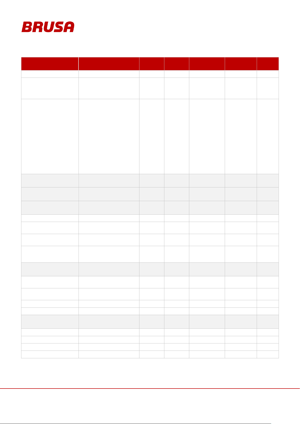
Technical data
and start-up
EVB1-350/400-40-HP
90
NAME
CODE (HEX)
DESCRIPTION
START BIT
BIT LENGTH
TRANSMISSION
MODE
CYCLE TIME
UNIT
BMS_CMD_BALANCING_EN
Clearance for balancing
2 1 Cyclic
-
-
BMS_CMD_RESET_AH
Resetting AH meter (BCM_Ah
and BATT_DoD). Precondition:
BMS_State =
BMS_NLG_CHARGER
3 1 Cyclic
-
-
BMS_CMD_FAN
0x0 = Automatic
0x1 = FAN off
0x2 = FAN 10%
0x3 = FAN 20%
0x4 = FAN 30%
0x5 = FAN 40%
0x6 = FAN 50%
0x7 = FAN 60%
0x8 = FAN 70%
0x9 = FAN 80%
0xA = FAN 90%
0xB = FAN 100%
8 4 Cyclic
-
-
BMS_PARAM_RX
0x400
-
-
-
NoMsgSendType
0
-
BMS_PARAM_TX
0x401
-
-
-
NoMsgSendType
0
-
CCU_Cell
0x302
-
- - Cyclic
10
-
CCU_Index
Current cell index
0 8 Cyclic
-
-
CCU_Number
Cell block (currently read by cell
index)
8 8 Cyclic
-
-
CCU_V
Voltage of the cell currently
being depicted by the cell index
24
16
Cyclic
-
mV
CCU_T
Temperature of the cell block
currently being depicted by the
CCU_Number
40
16
Cyclic
-
°C
CCU_Max
0x301
-
- - Cyclic
10
-
CCU_V_HIGH_PEAK
Highest cell voltage over a
period of 1 ms
8
16
Cyclic
-
mV
CCU_V_LOW_PEAK
Lowest cell voltage over a period
of 1 ms
24
16
Cyclic
-
mV
CCU_T_HIGH
Highest cell block temperature
40
16
Cyclic
-
°C
CCU_T_LOW
Lowest cell block temperature
56
16
Cyclic
-
°C
CCU_V
0x300
-
- - Cyclic
10
-
CCU_V_HIGH
Highest cell voltage
8
16
Cyclic
-
mV
CCU_V_HIGH2
Second highest cell voltage
24
16
Cyclic
-
mV
CCU_V_LOW2
Second lowest cell voltage
40
16
Cyclic
-
mV
CCU_V_LOW
Lowest cell voltage
56
16
Cyclic
-
mV
Page 91
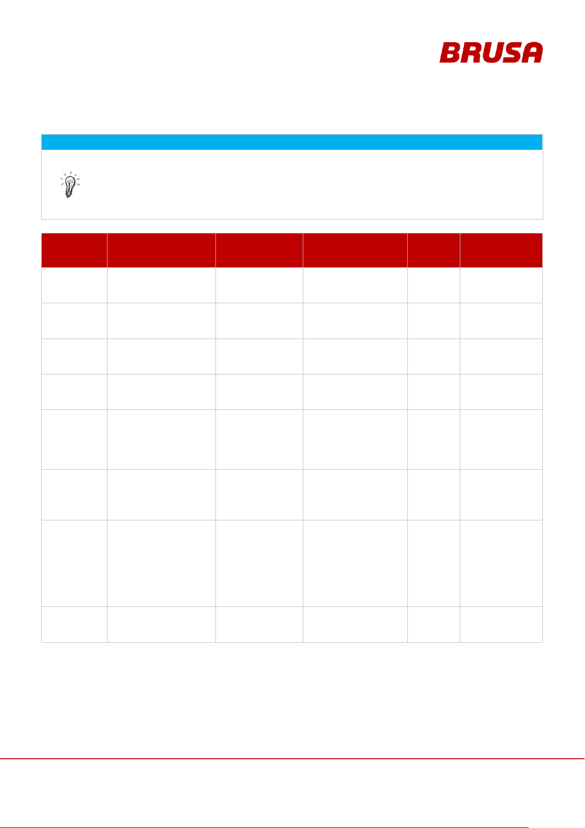
91
Technical data
and start-up
EVB1-350/400-40-HP
11.2 CAN Signals / Errorand Warning Messages
INFORMATION
Error messages can basically be divided in the following categories:
E (Error): Errors (generally lead to a shut-down of the system)
TE (Temporary Error): Temporary errors (can generally be acknowledged)
W (Warning): Warnings (show the nearing or reaching of a
limit)
ERROR TYPE
ERROR CODE
(HEX / DEC)
CAN SIGNAL
DESCRIPTION
CAUSE
SET
CONDITION
RESET CONDITION
E
0x8000
32768
BMS_Err_Stored
During every start-up a
storage address is
checked
A storage cell delivers a
different value to that which
is depicted
0
At new Kl_15 start up
E
0x4000
16348
BMS_Err_EEprom
Communication error
via the SPI with
EEPROM
Return value of the
eeprom_xxx function
generates an error
0
At new Kl_15 start up
E
0x2000
8192
BMS_Err_Flash
During every start-up a
CRC check of the flash
is carried out
CRC error
0
At new Kl_15 start up
E
0x1000
4096
BMS_Err_NVSRam
CRC error with the
important PARAM
values
CRC at PARAM 0x80 - 0xFF
= 0x0000
0
At new Kl_15 start up
E
0x0800
2048
BMS_Err_CcuCapture
No valid cell voltage
measurement
CCU_V_LOW < 2 V
or
CCU_V_LOW >
CCU_V_HIGH
(BMS_War_CellVoltageDiff
is then also set)
12x
(3-12 cycles)
At new Kl_15 start up
E
0x0400
1024
BMS_Err_CcuIndex
Number of cells
identified does not
correspond to the
number defined over
PARAM
No CCU_RESET_BACK
signal received or PARAM
value is wrong
10x
(max. 10x
cycle time of
120 cells)
At new Kl_15 start up
E
0x0200
512
BMS_Err_CellPwm
No valid data from the
CCU or deviation of
Highest_V or Lowest_V
more than the max.
Delta_V (PARAM)
CCU_V > CCU_V_HIGH +
250 mV [5.4]
or
CCU_V + 250 mV [5.4] <
CCU_V_LOW
or
CCU_V < 2 V
or
CCU_V > 4.5 V
10x
At new Kl_15 start up
E
0x0100
256
BMS_Err_TempSensor
Sensor value is outside
realistic value
CCU_T_LOW < -40°C [10.2]
OR CCU_T_HIGH >
100°C [10.1]
Filtered
At new Kl_15 start up
Page 92

Technical data
and start-up
EVB1-350/400-40-HP
92
ERROR TYPE
ERROR CODE
(HEX / DEC)
CAN SIGNAL
DESCRIPTION
CAUSE
SET
CONDITION
RESET CONDITION
E
0x0080
128
BMS_Err_OverCharge
One cell voltage is
higher than permitted
and charging is
continued
Highest cell voltage [Ri] >
4.15 V [6.4]
and
it has been overcharged by
more than 0.5 Ah [11.3]
or
highest cell voltage [Ri] >
4.2 V [6.5]
and
it has been overcharged by
more than 0.01 Ah or for
longer than 250 ms
Ah
At new Kl_15 start up
E
0x0040
64
BMS_Err_OverDischarge
One cell voltage is
lower than permitted
and discharging is
continued.
Lowest cell voltage [Ri] <
3.0 V [6.13]
and
it has been over-discharged
by more than 0.5 Ah [11.3]
or
lowest cell voltage [Ri] <
2.6 V [6.14]
and
it has been over-discharged
by more than 0.01 Ah or for
longer than 250 ms
Ah
At new Kl_15 start up
E
0x0020
32
BMS_Err_CurrentCharge
Max. charging current
exceeded
BCM_A < -210 A [6.8]
Average
value over
2.5 s
At new Kl_15 start up
E
0x0010
16
BMS_Err_CurrentDischarge
Max. discharging
current exceeded
BCM_A > 630 A [6.17]
Average
value over
2.5 s
At new Kl_15 start up
E
0x0008
8
BMS_Err_PreCharge
An error during precharging
Deviation of the output
voltage larger than 10 V [4.1]
or
a current of over 3 A has
been flowing for too long
[4.2]
5 s [4.4]
At new Kl_15 start up
E
0x0004
4
BMS_Err_ShortCircuit
Short circuit
BCM_Discharge or
BCM_Charge 5x max.
frequency
4.88 ms
At new Kl_15 start up
E
0x0002
2
BMS_Err_Interlock
Interlock open
No signal during interlock
Still not active
10 ms
At new Kl_15 start up
E
0x0001
1
BMS_Err_NotAus
Emergency stop
pressed
No signal during emergency
stop
10 ms
At new Kl_15 start up
TE
0x8000
32768
BMS_TErr_CanRxCmd
Message not
received anymore
EvCanRxCmd timeout after
1050 ms
0
Receipt of a message
TE
0x4000
16348
BMS_TErr_CanRxNlg
Still not active
Still not active
0
Receipt of a message
TE
0x2000
8192
BMS_TErr_bit2 - -
0
At new Kl_15 start up
Page 93

93
Technical data
and start-up
EVB1-350/400-40-HP
ERROR TYPE
ERROR CODE
(HEX / DEC)
CAN SIGNAL
DESCRIPTION
CAUSE
SET
CONDITION
RESET CONDITION
TE
0x1000
4096
BMS_TErr_bit3 - -
0
At new Kl_15 start up
TE
0x0800
2048
BMS_TErr_bit4 - -
0
At new Kl_15 start up
TE
0x0400
1024
BMS_TErr_bit5 - -
0
At new Kl_15 start up
TE
0x0200
512
BMS_TErr_VoltageDivCCU
Total voltage
measurement differs
from the sum of the
cell voltages
BCM_U1 or BCM_U2
deviation of
BATT_Voltage_Act of more
than 10 V [11.1]
5000 ms
At new Kl_15 start up
OR BMS_State =
BMS_SHUTDOWN
AND
not set condition
TE
0x0100
256
BMS_TErr_VoltageDivBCM
Voltage
measurement before
and after contactor
are too different from
one another
Deviation of BCM_U1 from
BCM_U2 of more than
10 V [11.1]
5000 ms
At new Kl_15 start up
OR BMS_State =
BMS_SHUTDOWN
AND
not set condition
TE
0x0080
128
BMS_TErr_bit8 - -
0
At new Kl_15 start up
TE
0x0040
64
BMS_TErr_ChargeI2t
The Charge load
duration of the battery
is too long
I2 t of under 120A [6.6] <
64000 A2s [6.7, 6.9]
0
At new Kl_15 start up
TE
0x0020
32
BMS_TErr_CellVoltageDiff
Too great a
difference between
the cell voltages with
too large a current
flow
CCU_V_HIGH CCU_V_LOW >400 mV [5.5]
and
BCM_A > 20 A [5.6]
and
BMS_War_OverDischarge =
0
0
At new Kl_15 start up
OR BMS_State =
BMS_SHUTDOWN
AND
BMS_War_CellVoltag
eDiff = 0
TE
0x0010
16
BMS_TErr_NLG
NLG reports fault
Report received from NLG
0
At new Kl_15 start up
OR BMS_State =
BMS_SHUTDOWN
AND
Report received from
NLG
TE
0x0008
8
BMS_TErr_FuseI2t
The peak load
duration of the battery
is too long
I2 t of over 600A [7.1] >
10000 A2s [7.3]
0
At new Kl_15 start up
OR BMS_State =
BMS_SHUTDOWN
AND
I2t = 0
TE
0x0004
4
BMS_TErr_DischargeI2t
The discharge load
duration of the battery
is too long
I2 t of over 320 A [6.15] >
784000 A2s [6.16, 6.18]
0
At new Kl_15 start up
OR BMS_State =
BMS_SHUTDOWN
AND
I2t = 0
Page 94

Technical data
and start-up
EVB1-350/400-40-HP
94
ERROR TYPE
ERROR CODE
(HEX / DEC)
CAN SIGNAL
DESCRIPTION
CAUSE
SET
CONDITION
RESET CONDITION
TE
0x0002
2
BMS_TErr_OverTemperature
Temperature above
the max. value
CCU_T_HIGH > 46°C [10.3]
and
I2 t of under -2 A [11.3] >
12000 A2s
or
CCU_T_HIGH > 56°C [10.7]
and
BATT_Current_Act <
2 A [11.2]
0
At new Kl_15 start up
OR BMS_State =
BMS_SHUTDOWN
AND
BMS_MODE_OTP = 0
TE
0x0001
1
BMS_TErr_UnderTemperature
Temperature under
the min. value
CCU_T_LOW < 9°C [10.6]
and
I2t of under -2 A [11.3] >
12000 A2s
or
CCU_T_LOW < -11°C
[10.10]
and
BATT_Current_Act
>2 A [11.2]
0
At new Kl_15 start up
OR BMS_State =
BMS_SHUTDOWN
AND
BMS_MODE_UTP = 0
W
0x8000
32768
BMS_War_CanOff
CAN controller sets
the BUS OFF bit
CAN controller sets the BUS
OFF bit
0
Not set condition
W
0x4000
16348
BMS_War_CanRx
CAN receive error
counter > 127
CAN receive error counter >
127
0
Not set condition
W
0x2000
8192
BMS_War_CanTx
CAN transmit error
counter > 127
CAN transmit error counter >
127
0
Not set condition
W
0x1000
4096
BMS_War_CanValue
Received CAN value
reduced to
acceptable range
CAN value outside valid
range
0
Not set condition
W
0x0800
2048
BMS_War_Watchdog
Watchdog overflow
(32.64 ms); the
internal watchdog is
refreshed every
0.66 ms
Watchdog overflow
(32.64 ms); the internal
watchdog is refreshed every
0.66 ms
0
Not set condition
W
0x0400
1024
BMS_War_EEPROM
Data could not be
saved in the
EEPROM
Error while writing into the
EEPROM
0
Start-up
W
0x0200
512
BMS_War_bit6 - -
0
Not set condition
W
0x0100
256
BMS_War_bit7 - -
0
Not set condition
W
0x0080
128
BMS_War_OverCharge
The alert threshold
has been surpassed
Highest cell voltage [Ri] >
4.1 V [6.3]
0
Not set condition
W
0x0040
64
BMS_War_OverDischarge
The alert threshold
has been surpassed
Lowest cell voltage [Ri] <
3.4 V [6.10]
0
Not set condition
Page 95

95
Technical data
and start-up
EVB1-350/400-40-HP
ERROR TYPE
ERROR CODE
(HEX / DEC)
CAN SIGNAL
DESCRIPTION
CAUSE
SET
CONDITION
RESET CONDITION
W
0x0020
32
BMS_War_CellVoltageDiff
Too great a
difference of the cell
voltages
CCU_V_HIGH CCU_V_LOW > 400 mV*
2/3[5.5]
0
Not set condition
W
0x0010
16
BMS_War_NLG
NLG reports fault
Report received from NLG
0
Not set condition
W
0x0008
8
BMS_War_OverCurrentCharge
Recommended
charging current is
exceeded
BATT_Current_Act +
2A[11.2] < BATT_CurrentChargeMax
0
Not set condition
W
0x0004
4
BMS_War_OverCurrentDischar
ge
Recommended
discharging current is
exceeded
BATT_Current_Act –
2 A [11.2] >
+BATT_CurrentDischargeM
ax
0
Not set condition
W
0x0002
2
BMS_War_OverTemperature
Temperature above
the recommended
range
CCU_T_HIGH > 43°C [10.4]
and
BATT_Current_Act < -2 A
[11.2]
or
CCU_T_HIGH > 53°C [10.8]
and
BATT_Current_Act > 2 A
[11.2]
0
Not set condition
W
0x0001
1
BMS_War_UnderTemperature
Temperature below
the recommended
range
CCU_T_LOW < 12°C [10.5]
and
BATT_Current_Act < -2 A
[11.2]
or
CCU_T_LOW < -8°C [10.9]
and
BATT_Current_Act > 2 A
[11.2]
0
Not set condition
Page 96

Technical data
and start-up
EVB1-350/400-40-HP
96
12 Warranty
The company BRUSA Elektronik AG provides a warranty period of 24 months after the date of purchase provided
there are uniquely verifiable material and workmanship defects in the electronic components. For the individual cell
packets a guarantee time of 12 months or 800 full cycles (depending on first start-up) is granted.
The guarantee acceptance becomes invalid immediately if the seal on the housing is damaged through
unauthorised opening or if it is not there at all!
Furthermore, BRUSA Elektronik AG accepts absolutely no liability for damage which results from incorrect or
improper handling of the device!
For damage to persons which results from non-observance of the general and product-specific safety guidelines,
no liability claims can be asserted against BRUSA Elektronik AG!
For damage to peripheries which results in connection with this device, BRUSA Elektronik AG can accept no
liability! If anything is unclear regarding the operation of this product, we would ask you to sort this out with our
support team BEFORE you start the installation!
13 Instructions for Disposal
Because this product is a dangerous good, the battery may only be dismantled and disposed of by specialist
personnel instructed and trained by the company BRUSA Elektronik AG! Therefore if any sort of disposal is
planned you must contact the company BRUSA Elektronik AG beforehand at the manufacturer address given in
chapter 4.6!
The company BRUSA accepts absolutely no liability for any type of damage resulting from disposal activity by
unqualified personnel!
Page 97

97
Technical data
and start-up
EVB1-350/400-40-HP
14 Index
B
Balancing ................................................................................... 36
Battery
GND Connection ................................................................... 44
Product-Lifespan Guidelines ................................................. 12
Programming ........................................................................ 50
Reset ..................................................................................... 50
Specification.......................................................................... 27
Block Diagram
Basic Concept of Battery ....................................................... 33
Installation into the Vehicle .................................................. 30
Operation Modes ............................................................ 41, 42
BMS............................................................................................ 38
Current Monitoring ............................................................... 18
Over-voltage Monitoring ...................................................... 19
Regulation of the Cell Voltage .............................................. 36
Under-voltage Monitoring .................................................... 19
BMS_Monitor
Analysing the MDF File ......................................................... 74
C
Cable connections
Instructions and Cross-sections ............................................ 27
CAN Parameters ........................................................................ 82
CAN Signals
Description ............................................................................ 91
Controller ................................................................................... 47
Cooling System
Connections .......................................................................... 43
Effect ............................................................................... 58, 59
Specification.......................................................................... 27
Customer Package ..................................................................... 22
D
Derating ............................................................................... 15, 18
Device Designation
Decoding ................................................................................. 3
Discharging 80 A .................................................................... 56
EVB1-400-40-HP
Charging 120 A ...................................................................... 54
Discharging 320 A peak ......................................................... 55
Discharging 600 A peak ......................................................... 55
Discharging 80 A .................................................................... 54
F
Firmware .............................................................................. 50, 85
Programming Requirements ................................................. 47
G
Ground Connection .................................................................... 46
H
High voltage
The 5 Safety Rules ................................................................. 14
I
Installation Position ................................................................... 39
Interlock
Principle of operation............................................................ 31
Inverter
Start-up requirements .......................................................... 46
M
Main Contactor
Function ................................................................................ 34
Installation Location .............................................................. 38
P
Pictograms ................................................................................... 9
Pre-charging Contactor
Function ................................................................................ 34
Installation Location .............................................................. 38
Pre-charging High Voltage ......................................................... 34
Pressure balance membrane ..................................................... 38
E
Error Code
Decoding ............................................................................... 91
EVB1-350-40-HP
Charging 120 A ...................................................................... 56
charging 200 A ...................................................................... 56
Discharging 320 A peak ......................................................... 57
Discharging 600 A peak ......................................................... 57
S
Safety
Important Instructions .......................................................... 11
T
Temperature Measurement ...................................................... 15
Page 98

Technical data
and start-up
EVB1-350/400-40-HP
98
V
Validity of the Manual.................................................................. 3
 Loading...