

BRUSA Elektronik AG
Neudorf 14
CH-9466 Sennwald
+41 81 758 19 00
info@brusa.biz
www.brusa.biz
TECHNICAL DATA
AND STARTUP
Translation of the original German operating instructions.
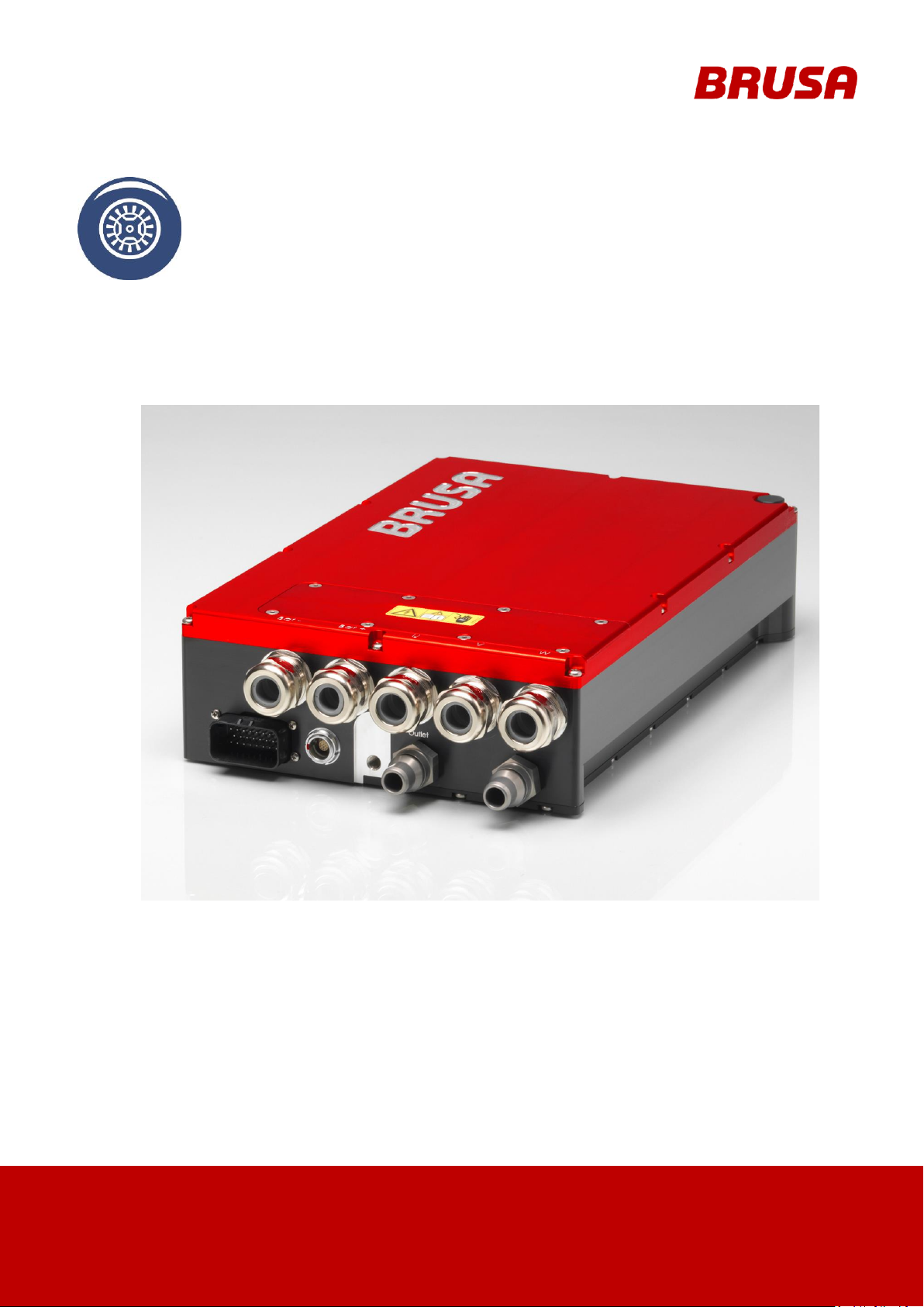
DMC514 (ISU)
DMC524 (ISU)
DMC534 (ISU)
DMC544
2
Technical data
and startup
LEGAL NOTICE
Publisher
BRUSA Elektronik AG
Neudorf 14
CH-9466 Sennwald
T +41 81 758 19- 00
Fax: +41 81 758 19 - 99
www.brusa.biz
office@brusa.biz
Date of issue
11. October 2011
Copyright
© 2011
The content of this document may not be passed on to third parties without the written authorisation
of the company BRUSA Elektronik AG- not even in extracts. Any technical information, drawings and
photos used are copyrighted and failure to respect this constitutes a punishable offence!
Updates
In light of the further technical development of our products, we reserve the right for structural
changes. Any changes will be disclosed in the relevant manuals through the replacement of the
relevant pages and/or a revision of the electronic data storage device.
Writer / Author
Holger Schmidt
REVISION
DATE
NAME
CHANGE
rev11
04.06.2015
F. Müller
- chap. 9.5 add information about cable and terminal insert
rev12
30.09.2015
M. Voppichler
- chap. 8.3.5 “Pin 9 CNH, Pin 10 CNL (CAN-Bus, CANInterface)” deleted
- chap. 8.4 “LV current consumption” added
- Cooling system warnings added (chap. 8.7)
rev13
18.11.2015
M. Voppichler
- adjusted delivery content
- adjusted diameters of cooling water connections
rev14
29.04.2016
M. Voppichler
- adjusted delivery content
- Warning about terminal insert (chap. 9.5)
- Chap. 12 added
rev15
28.11.2016
A. Girod
- Chapter 14 Warranty new
rev16
02.05.2017
M. Cvorak
- Chapter 8.3, LV input voltage range
rev17
15.09.2017
M. Cvorak
- Chapter 4.3, DEL: LEMO-cable from “delivered content”
REVISIONS

3
Technical data
and startup
VALIDITY
TYPE
DMC514 (ISU) - Ser.No. > 1000
DMC524 (ISU) - Ser.No. > 1000
DMC534 (ISU) - Ser.No. > 1000
DMC544 - Ser.No. > 1000
This manual is valid only for the following devices:

Technical data
and startup
4
Table of contents
1 Foreword .............................................................................................................................. 7
2 List of abbreviations ........................................................................................................... 7
3 Safety and warning instructions ........................................................................................ 8
3.1 Symbols and their meaning ........................................................................................................ 8
3.2 Safety instructions and danger levels ......................................................................................... 9
3.3 Generally applicable safety measures ...................................................................................... 10
3.3.1 Safety instructions for cooling water systems .................................................................... 10
3.3.2 Safety instructions for mechanical systems ....................................................................... 10
3.3.3 Safety instructions for handling and operation ................................................................... 11
3.3.4 Safety instructions for electrical systems ........................................................................... 12
3.4 Safety installations / power limitations ...................................................................................... 13
3.4.1 Interlock ............................................................................................................................ 13
3.4.2 Short-circuit protection ...................................................................................................... 13
3.4.3 Automatic discharge of DC-link voltage ............................................................................. 14
3.4.4 Monitoring of HV voltage ................................................................................................... 14
3.4.5 Overload protection (derating) ........................................................................................... 14
3.4.6 Inverter safety unit (ISU).................................................................................................... 14
3.5 Safety measures for vehicle installation .................................................................................... 15
3.5.1 Principle of operation Interlock .......................................................................................... 15
3.6 Requirements for the start-up personnel .................................................................................. 16
4 General ............................................................................................................................... 17
4.1 Content and scope of this manual ............................................................................................ 17
4.2 Scope of the entire documentation ........................................................................................... 17
4.3 Delivered mechanical components ........................................................................................... 18
4.4 Optional delivery contents ........................................................................................................ 20
4.5 EU-guidelines ........................................................................................................................... 21
4.6 Contact information of the manufacturer ................................................................................... 21
5 Intended use of the device ............................................................................................... 22
5.1 Proper use................................................................................................................................ 22
5.2 Improper use / limits of the product .......................................................................................... 23
6 About this device............................................................................................................... 24

5
Technical data
and startup
6.1 Technical data .......................................................................................................................... 24
6.2 Type plate ................................................................................................................................ 26
6.3 Device warnings ....................................................................................................................... 27
6.4 Basic function ........................................................................................................................... 27
6.5 Covers ...................................................................................................................................... 28
6.6 Assembly information ............................................................................................................... 29
6.6.1 Installation position ............................................................................................................ 29
6.6.2 Fixing (as in example DMC524) ........................................................................................ 29
6.7 Example of use ........................................................................................................................ 30
6.8 Input and output values ............................................................................................................ 31
6.9 Block diagram output stage / power print .................................................................................. 32
6.10 Operating modes of the inverter ............................................................................................... 33
6.11 Regulatory approach and limitations ........................................................................................ 34
6.12 Error and warning messages .................................................................................................... 34
6.12.1 Error definition ................................................................................................................... 35
6.12.2 Warning message definition .............................................................................................. 35
7 Level of inverter efficiency ............................................................................................... 36
7.1 DMC514 measured with HSM1-10.18.04 at 400V (first quadrant) ............................................ 36
7.2 DMC524 measured with HSM1-6.17.12 at 400V (first quadrant) .............................................. 36
7.3 DMC534 measured with HSM1-10.18.13 at 400V (first quadrant) ............................................ 37
7.4 DMC544 measured with HSM1-10.18.13-W7 at 400V (first quadrant) ...................................... 37
8 Connections ....................................................................................................................... 38
8.1 Circuit connections ................................................................................................................... 38
8.2 Pin assignment motor sensor connection (device side) ............................................................ 39
8.3 Pin assignment of control connector (device side) .................................................................... 40
8.3.1 Pin 1 GND (ground terminal 31) ........................................................................................ 41
8.3.2 Pin 2 AUX (Wiring system terminal 30) .............................................................................. 41
8.3.3 Pin 3 EN (Enable, Power ON) ........................................................................................... 42
8.3.4 Pin 8 PG1, 14 PG2, 15 PG3 (Reserve ground, RS232 ground) ......................................... 42
8.3.5 Pin 11 TXD, Pin 12 RXD (RS232 interface) ....................................................................... 43
8.3.6 Pin 13 PRO (Enable firmware programming)..................................................................... 44
8.3.7 Pin 17 EXT AW1, Pin 18 EXT AW2 (External shut down path 1 + 2) ................................. 45
8.3.8 Pin 19 IL1, Pin 20 IL2 (Interlock 1 + 2) .............................................................................. 46

Technical data
and startup
6
8.4 LV current consumption............................................................................................................ 47
8.4.1 I
8.4.2 I
..................................................................................................................................... 48
Aux
+ IEn + I
Aux
Ext AW1
+ I
................................ ................................................................ .. 49
Ext AW2
8.5 Grounding screw ...................................................................................................................... 50
8.6 Cooling water connections ....................................................................................................... 51
8.7 Cooling circuit Information and Warnings ................................................................................. 52
8.7.1 Cooling water filter............................................................................................................. 52
9 Start-up ............................................................................................................................... 53
9.1 System requirements for PARAM-tool software ........................................................................ 54
9.2 Ventilate and check cooling system .......................................................................................... 54
9.3 Load motor parameter table onto inverter ................................ ................................................. 54
9.4 Build HV supply ........................................................................................................................ 55
10 Operation of the inverter through CVI ................................ .......................................... 59
10.1 Build connection between CVI and the inverter ........................................................................ 60
10.2 Disconnect the communication between CVI and the inverter / Switch off the inverter ............. 60
10.3 Fix CVI problems ...................................................................................................................... 61
11 Error correction .............................................................................................................. 62
12 Flooding in the device ................................................................................................... 62
13 Instructions for disposal ............................................................................................... 63
14 Warranty and guarantee ................................................................................................ 64
15 Index ................................................................................................................................ 65

7
Technical data
and startup
1 Foreword
ABBR.
MEANING
ABBR.
MEANING
AUX
Wiring System Plus
Terminal 30
DMC
Digital Motor Controller
DMC5x4
DMC514 inverter, 524,534 and 544
IL1:
Interlock
EN
Device activation
Terminal 15
IL2:
Interlock
GND
Minus wiring System, vehicle ground
Terminal 31
ISU:
Inverter Safety Unit
High
High level (logic level)
Low
Low level (logic level)
HV
High voltage, DC-link voltage
(high voltage)
LV
Low voltage
HV+
High voltage plus (high voltage+)
LV+
Low voltage plus (low voltage+)
HV-
High voltage minus (high voltage-)
LV-
Low voltage minus (low voltage-)
Dear customer!
With the BRUSA inverter DMC5x4 you have received a very capable and versatile product. As this is a component
of high performance electronics, we require specialist knowledge in the dealing with as well as the operation of the
product!
Read the manual - particularly the chapter 3 Safety and warning instructions - carefully before you inverter
DMC5x4 or carry out any other work!
2 List of abbreviations
Throughout this manual, some specific technical abbreviations are used. You will find an overview as well as their
meaning in the following table:

Technical data
and startup
8
PROHIBITION SYMBOLS
SYMBOL
MEANING
SYMBOL
MEANING
General prohibition
Warning high voltage
Touching forbidden
Switching on forbidden
WARNING SYMBOLS
SYMBOL
MEANING
SYMBOL
MEANING
General hazard warning
Electromagnetic field warning
Potentially explosive warning
Battery hazard warning
Hot surface warning
High electrical voltage warning
High pressure warning / fluid spurting out
Fire hazard warning
MANDATORY SIGNS
SYMBOL
MEANING
SYMBOL
MEANING
Disconnect device from voltage
Disconnect device from mains
INFORMATION SIGNS
SYMBOL
MEANING
SYMBOL
MEANING
Important information on avoiding possible
damage to property
Important information
3 Safety and warning instructions
In this chapter you will find safety instructions which apply to this device. These refer to assembly, start-up and
running operation in the vehicle. Always read and observe these instructions in order to protect people's safety and
lives and to avoid damage to the device!
3.1 Symbols and their meaning
Throughout this manual, some specific technical abbreviations are used. You will find an overview as well as their
meaning in the following table:

9
Technical data
and startup
3.2 Safety instructions and danger levels
DANGER
This instruction warns against serious, irreversible risks of injury and in some cases death!
Avoid these dangers by observing these instructions!
WARNING
This instruction warns against serious, irreversible risks of injury!
Avoid these dangers by observing these instructions!
CAUTION
This instruction warns against serious, irreversible risks of injury!
Avoid these dangers by observing these instructions!
INSTRUCTION
This instruction warns against possible damages to property if the following instructions and work
procedures are not observed.
INFORMATION
This type of instruction discloses important information for the reader.

Technical data
and startup
10
WARNING
Spurting cooling fluid!
Skin burning hazard!
Check the tightness of the cooling water system, particularly the pipes, screw joints and pressure
tanks.
Resolve recognisable leakages immediately!
DANGER
Potential explosion area!
Danger to life!
Do not store any highly flammable materials or combustible fluids in the direct surroundings of the
device!
Sparks at the device connections can set these on fire and lead to explosions!
CAUTION
Hot surfaces!
Burn hazard!
The device produces high temperatures when in operation!
Handle the device with care and caution!
3.3 Generally applicable safety measures
The following safety measures have been developed based on the knowledge of the manufacturer. They are not
complete, they can be supplemented by place and/or country specific safety instructions and guidelines for
accident prevention!
The present safety instructions from the system integrator and/or distributor must therefore be supplemented by
specific country and local guidelines.
3.3.1 Safety instructions for cooling water systems
3.3.2 Safety instructions for mechanical systems

11
Technical data
and startup
3.3.3 Safety instructions for handling and operation
INSTRUCTION
A high cooling water temperature reduces the life span! So take ongoing care to ensure sufficient
cooling of the device!
Do not place the device in direct sunlight and in close proximity to heat sources!
Although if the device has high IP protection, you should avoid placing it in direct contact with water
(rain, spurting water) if possible!
Under no circumstances should you put a low-resistance connection between the HV contacts, the
housing contacts and the LV contacts! This will lead to malfunctions and furthermore to the
destruction of the device!
Prevent any penetration of fluids into the device (e.g. during assembly work)! The penetration of fluids
will lead to a short circuit and subsequent damage to the device!
Under no circumstances should you operate the device if liquid is leaking in anywhere, refer
immediately to the company BRUSA Elektronik AG!

Technical data
and startup
12
DANGER
High voltage!
Danger to life!
Under no circumstances should you touch the HV wires or HV connections without ensuring that
there is no voltage beforehand!
The device may only be connected by a qualified electrician!
Under no circumstances should you bypass or avoid security installations! Any malfunctions resulting
from this could have life threatening consequences!
Always use an insulation monitoring unit for ongoing monitoring of the galvanic isolation between HV
and LV circuits!
Before starting work with the device, the shut-down of the coupled motors must be ensured! Even
when the HV supply is switched off, a turning motor can still produce voltage!
INSTRUCTION
Under no circumstances should the device be opened without authorisation! The opening of the
device (housing sealed-up) leads directly to the forfeit of any guarantee and warranty rights!
INFORMATION
Adhere strictly to the following 5 safety rules when working on a HV grid:
Disconnect system from power.
Switch off the ignition
Remove service / maintenance plug and/or turn off main battery switch
Remove fuse
Ensure that system does not reconnect.
Keep ignition key safe to prevent unauthorised access.
Keep service / maintenance plug safe to prevent unauthorised access.
Use lockable cover cap to ensure that the main battery switch does not reconnect.
Check that it is not live with a suitable voltage tester (note voltage range!)
Ground and short-circuit the system.
Cover or seal-off adjacent live parts.
3.3.4 Safety instructions for electrical systems

13
Technical data
and startup
3.4 Safety installations / power limitations
INFORMATION
The pins IL1 and IL2 on the control connector must be connected and evaluated by the customer for
this.
1. Interlock switch
3.4.1 Interlock
The interlock switch (1) protects the operator from injuries from the HV connections. The interlock switch (1) is
automatically activated as soon as the service cap is opened.
3.4.2 Short-circuit protection
If a short-circuit of the power output stage is detected (e.g. short circuit of the motor phases) then the power output
stage is immediately deactivated. A corresponding error is detected over CAN. The error must be confirmed before
further operation.

Technical data
and startup
14
DANGER
High voltage!
Danger to life!
If the High voltage is present, the HV connections are live!
Under no circumstances should you touch the HV connections without ensuring that there is no
voltage beforehand!
In the case of additional connected capacities, consider a correspondingly longer discharge time!
INSTRUCTION
Continuous operation at the temperature limit will inevitably lead to a higher level of wear of the
components!
INFORMATION
In general, the customer or the integrator is responsible for the safety of the system, in which the
inverter is integrated. The device is set up for the use of an Inverter Safety Unit (ISU). This protective
function was developed in accordance with ISO26262 and can meet the criteria of ASIL-C.
The ISU is not a standard protective function and can be applied by BRUSA optionally.
You can find detailed information on the ISU on the attached sheet DMC_ISU.pdf
3.4.3 Automatic discharge of DC-link voltage
As soon as the voltage on the HV connections is switched off (manually or automatically), active discharge of DClink capacitors takes place in the inverter.
3.4.4 Monitoring of HV voltage
Integrated in the inverter is an overvoltage protective circuit, which deactivates the inverter immediately when the
HV voltage is too high (Error mode). A corresponding error is detected over CAN. The error must be confirmed
before further operation.
If the voltage of the HV input falls below the minimum voltage, the inverter is again deactivated (Error mode). A
corresponding error is detected over CAN. The error must be confirmed before further operation.
3.4.5 Overload protection (derating)
This security installation is the inverter's self-protection. If the inverter rises in temperature, this means a decrease
in power (derating) to protect the inverter from damage through overheating. The power will subsequently be
reduced until the temperature falls back to the target range.
The temperature measurement takes place in the high power switches and is set in the factory.
3.4.6 Inverter safety unit (ISU)

15
Technical data
and startup
3.5 Safety measures for vehicle installation
INFORMATION
This safety measure is a recommendation by the company BRUSA Elektronik AG and is understood
as a basic requirement for the safe operation of electric vehicles!
3.5.1 Principle of operation Interlock
The interlock switch (1) is closed if the corresponding interlock condition of each device is met (closed service
cover, plugged HV connections ...). The interlock evaluation of the PDU switches the 12V supply voltage (2) of the
HV contactors (4) in the battery if the interlock circuit is closed. The emergency stop switch (3) also interrupts the
12V supply voltage of the HV contactors (4). The second interlock (5) of the line insulation guard interrupts the
interlock circuit, if a fault in the HV- insulation is detected.

Technical data
and startup
16
3.6 Requirements for the start-up personnel
All courses of action described in this manual may only be carried out by a qualified electrician! Specialist staff is
defined as electricians who dispose of
professional training,
knowledge and experience in the field of electronics / electric mobility,
as well as knowledge of relevant requirements and dangers
which they can display in practice. Furthermore, they must be able to assess the work assigned to them
independently, detect possible dangers and establish necessary protection measures.

17
Technical data
and startup
4 General
INFORMATION
To start up the inverter successfully, you will need the entire documentation as well as different
software and firmware. With the provision of the customer package, it is ensured that they are
complete and up-to-date. The updating of specific documents is carried out automatically and can be
seen in the history.
4.1 Content and scope of this manual
The present documentation gives the reader an overview of all required working steps in the installation and
operation of the device and the safety measures necessary for these.
Furthermore, you can find technical information, usage information and a basic description of the inverter and its
specific components.
The operation and safety instructions given in the previous chapters must be strictly adhered to ensure the ongoing
optimum functioning of the inverter and to meet the guarantee requirements of BRUSA Elektronik AG.
All work sequences and illustrations are based on the DMC524 model and are applicable to all model versions
mentioned in this handbook. In the case of model-specific deviations, corresponding instructions are available.
4.2 Scope of the entire documentation
The customer package includes the following indexes:
Manual:
Contains all information fundamentally necessary for the installation and operation of the inverter.
Firmware / motor table:
Contains the necessary firmware, a motor specific motor parameter table and instructions for installation.
Tools:
Contains additional tools for the operation, parameter setting and maintenance of the inverter.
Debugging / calibration:
Contains additional specific documentation for further work on the inverter (e.g. error analysis, rotor offset
adjustment).
History:
Listing of all upgrades within the customer package with a specification of the affected documents or software /
firmware etc.

Technical data
and startup
18
INFORMATION
The components stated below are contained in the delivery and are necessary for the start-up! In the
case of possible missing parts, please refer to the manufacturing address given in chapter 4.6.
INFORMATION
For the DMC544, you can use the same cable lugs as for the DMC534. The diameter of 70mm2
cables fits without problems into 50mm2 cable lugs and is qualified by BRUSA Elektronik AG.
MEANING
PIECES
ILLUSTRATION
1.
DMC5x4 inverter
1
2.
M8 x 10 screws for the cable lugs
6
3.
M8 serrated lock washer for M8 x 10 screws
6
4.
Cable lugs (compression cable lugs)
for HV and motor cables
M8 x 25 mm2 without insulation (DCMC514)
VOGT AG type. 3575A
M8 x 35 mm2 without insulation (DCMC524)
VOGT AG type. 3584A
M8 x 50 mm2 without insulation (DCMC534 and DMC544)
VOGT AG type. 3590A
5
5.
Cable lug (compression cable lugs)
for grounding
M8 x 25 mm2 90° without insulation (DCMC514)
GLOMAR AG type. DIN-25-08-W
M8 x 35 mm2 90° without insulation (DCMC524)
GLOMAR AG type. DIN-35-08-W
M8 x 50 mm2 90° without insulation (DCMC534 and DMC544)
GLOMAR AG type. DIN-50-08-W
1
4.3 Delivered mechanical components

19
Technical data
and startup
MEANING
PIECES
ILLUSTRATION
6.
23 pole control connector with crimp terminals
AMPSEAL 770680-1
1
7.
SN/LP contacts
AMPSEAL 770854-1
for wire diameter: 0.5 mm
2
We recommend the use of the following
crimping tool: Tyco 58440-1
25
8.
Normaquick cooling water connection pieces 0° Norma PS3
2
9.
Software package
(For a listing see chapter 4.2 Scope of the entire documentation)
1
---
10.
Entire documentation
(For a listing see chapter 4.2 Scope of the entire documentation)
1
---

Technical data
and startup
20
INFORMATION
These accessories can be obtained optionally from BRUSA Elektronik AG.
MEANING
TYPE
ILLUSTRATION
1.
Special key for HV cable fitting
RAAA041
---
2.
Normaquick cooling water connection pieces 90° Norma PS3
MHAA776
1.
M18x1.5 D16 cooling water connection
MAAA366
1.
Rubber seal for M18x1.5 D16 cooling water connection
MAAA365
2.
Protective cap for M18x1.5 D16 cooling water connection
MHAA682
3.
Cable glands for 13 mm - 18 mm cable diameter
RAAA040
4.
Cable glands for 9 mm - 16 mm cable diameter
RKAA144
5.
14 pole Lemo connecting cable (inverter - motor) 2 m
11140
6.
14 pole Lemo connecting cable (inverter - motor) 4 m
11141
7.
Spare- CEQ 25 mm2
11471
---
8.
Spare- CEQ 35 mm2
11472
9.
Spare- CEQ 50 mm2
11473
10.
Conversion switch resolver to digital
MHAA745
---
4.4 Optional delivery contents

21
Technical data
and startup
4.5 EU-guidelines
BRUSA Elektronik AG
Neudorf 14
9466 Sennwald
Switzerland
Phone:
+41 81 758 19 - 00
Fax:
+41 81 758 19 - 99
Internet:
www.brusa.biz
E-mail:
support@brusa.biz
This manual has been produced under the application and in respect of Inverter DMC5x4 EG guidelines, national
regulations and harmonised standards (EN) which were valid at the time of production.
4.6 Contact information of the manufacturer

Technical data
and startup
22
INFORMATION
This equipment is a custom built evaluation kit destined for professionals to be used solely at
research and development facilities for such purposes.
5 Intended use of the device
5.1 Proper use
The BRUSA DMC5x4 inverter has been designed for the following uses. In the case of planned operations in other
sections, please contact the company BRUSA Elektronik AG beforehand at the manufacturers address as given in
chapter 4.6.
The DMC5x4 inverter is a universal inverter for the driving of different three phase motors, such as for example:
Induction Motor or Asynchronous Motor (ASM)
Permanently Excited Synchronous Motor (PSM)
Hybrid synchronous motor (HSM)
Internal Permanently Excited Synchronous Motor (IPM)
The BRUSA DMC5x4 inverter has generally been designed for integration into power trains. The inverter can also
be operated in generator mode. This can be done in combination with a range extender (combustion motor for
range extension). In this way, the inverter is inserted between a generator and a battery to convert the produced
electricity and store it in the battery.

23
Technical data
and startup
5.2 Improper use / limits of the product
The carrying out of applications which do not conform to the conditions and requirements stated in the technical
documents and datasheets of the manufacturer is viewed as improper use.
The following limit values are set for the operation of the DMC5x4 inverter. Operation out with the defined limits can
also lead to life-threatening situations!
The following limit values are set for the DMC5x4 inverter by the manufacturer and must be adhered to in all cases:
Max HV input voltage (operation): 450 V
Max HV input voltage (without damage): 520 V
Min temperature of surroundings: - 40°C
Max temperature of surroundings: + 85°C
Min coolant temperature: - 40°C
Max coolant temperature: + 65°C
Maximum pressure cooling water system: 1.0 bar
The three-phase output voltage given out from the frequency inverter cannot be used to drive a one-
phase motor!

Technical data
and startup
24
HV AND LV POWER SUPPLY
DMC514
DMC524
DMC534
DMC544
UNIT
Min. Input voltage at terminal 15 (connect inverter)
6 6 6 6 V
Min. Input voltage at terminal 15 (automatic disconnection of the
inverter)
2 2 2 2 V
Min. HV input voltage for operation
(Software disconnection)
120
120
120
120
V
Min. HV input voltage for operation
130
130
130
130
V
Min. HV input voltage for full electrical output (V
DCmin
)
200
200
200
200
V
Max. HV input voltage (operation) (V
DCmax
)
450
450
450
450
V
HV input voltage software disconnection
460
460
460
460
V
HV input voltage hardware disconnection
480
480
480
480
V
Max. HV input voltage of device (without damage):
520
520
520
520
V
Max. protective fuse1)
150
300
450
600
A
X capacity (for HV pre-charging)
200
380
560
740
uF
Y capacity (for dimensioning of insulation monitoring unit)
98 + 98
128 + 128
158 + 158
188 + 188
nF
THREE PHASE OUTPUT U, V, W (R, S, T)
DMC514
DMC524
DMC534
DMC544
UNIT
RMS current duration (I
ACcont
)
112
225
337
450
A
Periodic cycle with max. current 30 sec 100%, 90 sec 50%
150
300
450
600
A
Continuous output (VDC=75%V
DCmax
, IAC=I
ACcont
, cosφ=0.9)1 (P
ACcont
) *1
39
79
118
160
kW
Max. output (VDC=75%V
DCmax
, IAC=I
ACmax
, cosφ=0.9)1 (P
ACmax
) *1
52
105
157
212
kW
PWM frequency (symmetric modulation) (f
PWM
)
24
24
24
24
kHz
Efficiency (VDC=75%V
DCmax
, PAC=P
ACcont
, cosφ=0.9)
*1
0.97
0.97
0.97
0.97
---
*1: 100% AC Sine Modulation, Phase-to-Phase AC Voltage amplitude = VDC
MECHANICS AND EQUIPMENT
DMC514
DMC524
DMC534
DMC544
UNIT
Height
88
88
88
88
mm
Width
240
240
240
240
mm
Length (without cable lugs and connections)
250
360
470
580
mm
Length (with cable lugs and connections)
276
386
496
606
mm
Weight (with cooling water)
6.5
9.5
12.5
15.5
kg
IP protection
IP67
IP67
IP67
IP67
---
CONNECTIONS
DMC514
DMC524
DMC534
DMC544
UNIT
HV+, HV- high voltage: 2 M8 cable lugs, recommended cable
diameter
25
35
50
70
mm2
Phases U, V, W: 3 M8 cable lugs, recommended cable diameter
25
35
50
70
mm2
23 pole AMP, wire diameter
0.5
0.5
0.5
0.5
mm2
Motor sensor connector, number of contacts
14
14
14
14
---
6 About this device
6.1 Technical data
1: semiconductor fuse for DC / e.g. fuse type FWH 500V from Bussmann

25
Technical data
and startup
THERMAL
DMC514
DMC524
DMC534
DMC544
UNIT
Amount of coolant in device
0.3
0.6
0.9
1.2
l
Flow rate
6-10
6-10
6-10
6-10
l/min
External diameter of cooling water connection pieces
18
18
18
18
mm
Minimum coolant temperature at inlet
- 40
- 40
- 40
- 40
°C
Maximum coolant temperature at inlet
+ 65
+ 65
+ 65
+ 65
°C
Coolant pressure drop @ 6l/min, T
coolant
= 25°C
(with a water to glycol mixture ratio of 50 / 50)
70
120
150
180
mbar
Maximum pressure of the coolant
1 1 1 1 bar
Maximum particle size in the coolant
0.2
0.2
0.2
0.2
mm
Ambient temperature range for storage
- 40 to
+ 85
- 40 to
+ 85
- 40 to
+ 85
- 40 to
+ 85
°C
Ambient temperature range in operation
- 40 to
+ 85
- 40 to
+ 85
- 40 to
+ 85
- 40 to
+ 85
°C
INSTRUCTION
The mixing ratio of glycol and water must be at least 50% / 50%. Apart from that, the inverter will
fail at low temperatures.
WARNING
When the abovementioned points based on the cooling are not complied, the inverter will fail!
Technical data
and startup
26
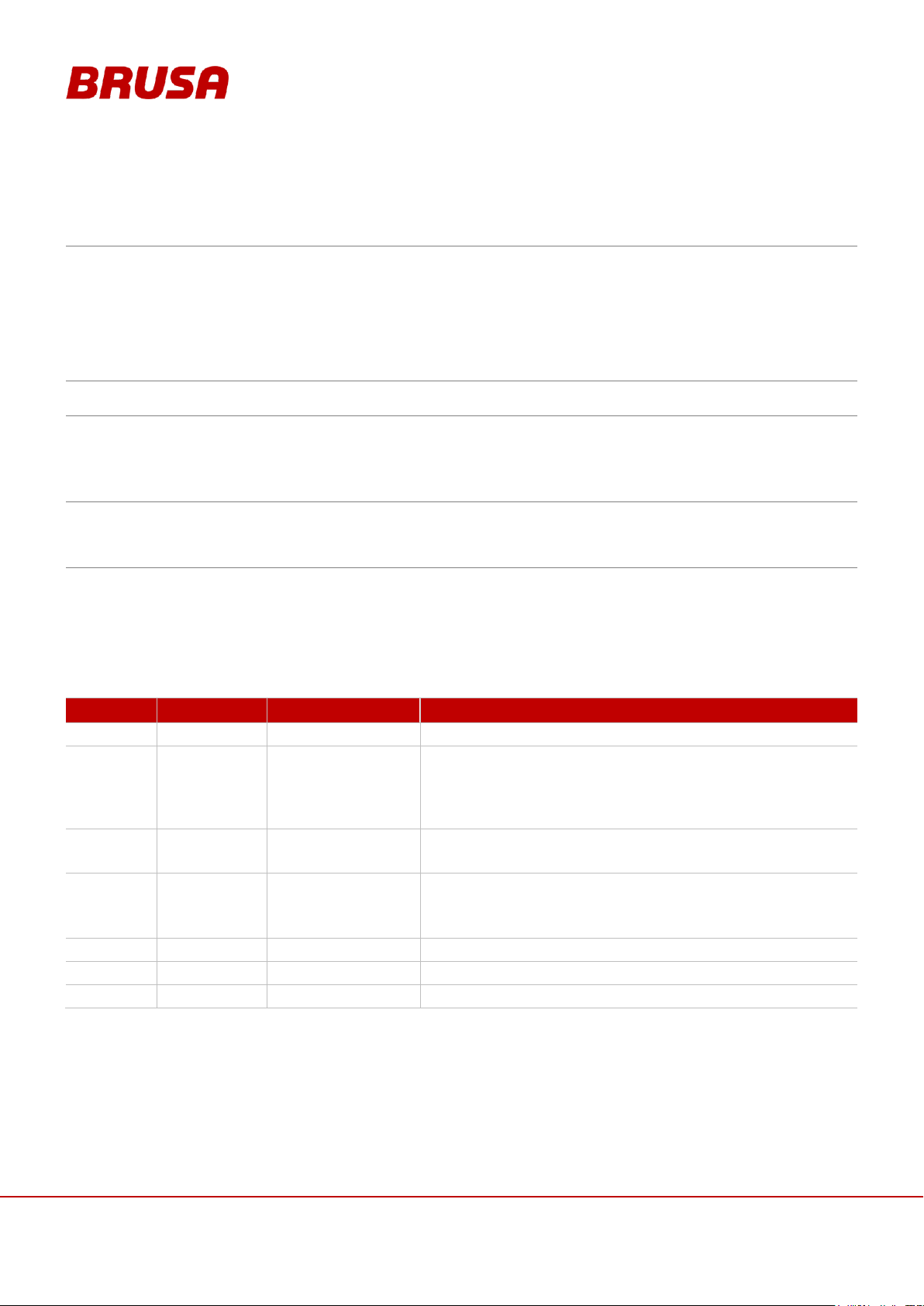
1. Classification
2. Operating voltage (section)
3. Maximum input current
4. Maximum coolant temperature at inlet
5. Serial number
6. IP protection category
7. Max. power
8. Maximum phase currents (U, V, W)
9. Level of efficiency
10. Date of manufacture
6.2 Type plate
The type plate is on the back of the device and contains the following information:

27
Technical data
and startup
6.3 Device warnings
Warning signs are installed on the device to warn the operator of possible dangers. Should one of these warning
signs fail or become illegible due to wear and tear, it must be immediately renewed! To get an original label, please
refer to BRUSA support at the manufacturing address given in chapter 4.6!
6.4 Basic function
The DMC5x4 inverter is a universal inverter which can be used to drive different three phase motors.
The power output stage of the DMC5x4 is based on the most capable, resonant SoftSwing® topology which was
developed and patented by BRUSA Elektronik AG. SoftSwing® topology achieves minimal switching losses and
excellent EMC features which are above average. Through this, the use of applications with motor frequencies of
up to 2 kHz is possible. With its very compact and easy assembly method, the DMC5x4 inverter is suitable for
practically any application.
To drive a motor, the corresponding motor parameter table is necessary. This must be tailored to the specific motor
by BRUSA who will also set the parameters!
Technical data
and startup
28
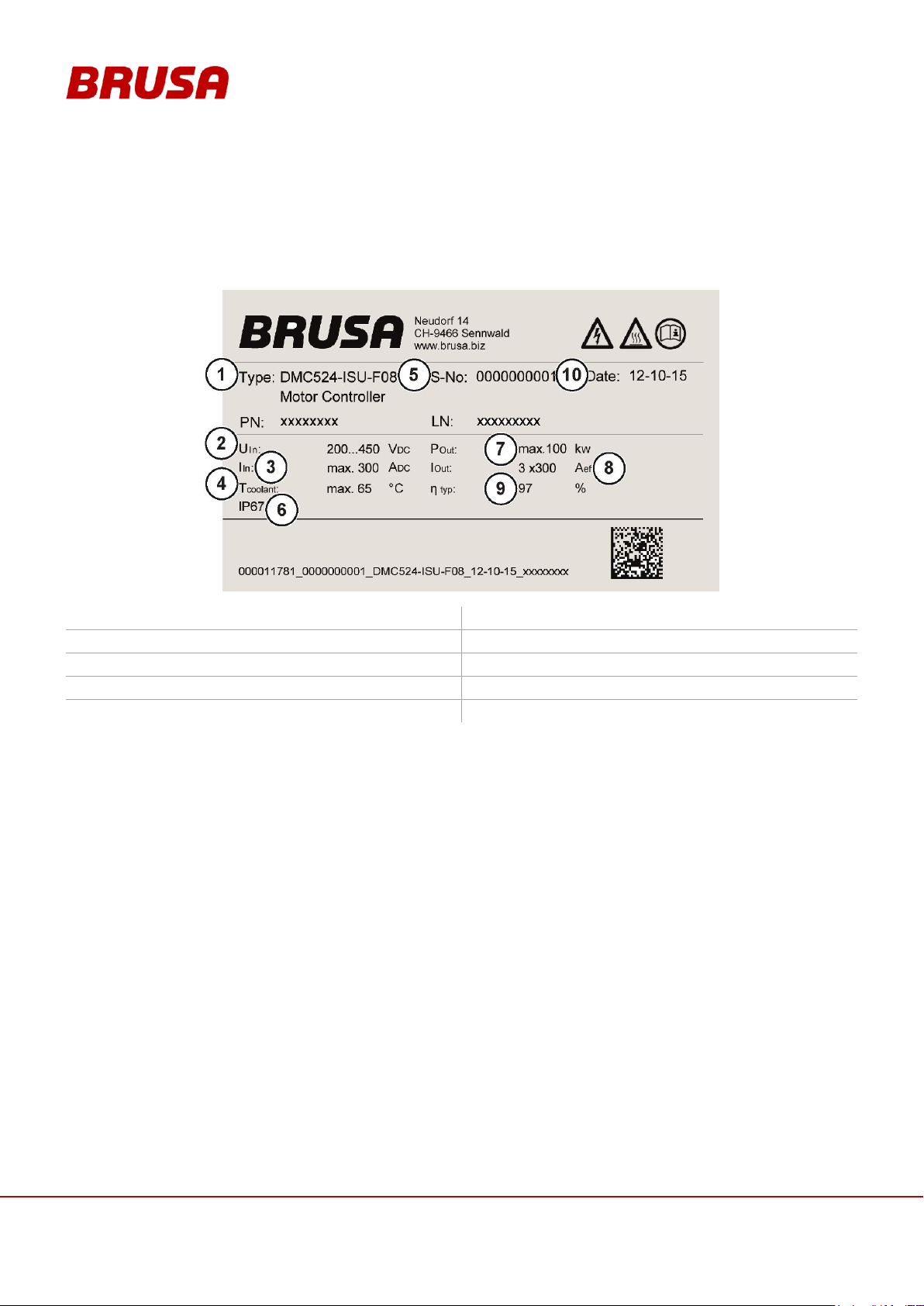
6.5 Covers
INFORMATION
Only the covers mentioned in this chapter may be removed by the customer!
Torque for M4 x 08 screws: 2.5 Nm
1. Service lid
2. M4 x 08 screws (8 pieces)

29
Technical data
and startup
6.6 Assembly information
INFORMATION
Recommended screw types:
Cylinder screw ISO 4762 - M6 x 30 - 8.8
or
Hexagon screw ISO 4017 - M6 x 30 - 8.8
Torque for M6 x 30 screws: 10 Nm +/-0.5
1. Screw fixing points (4 pieces)
6.6.1 Installation position
Even if the device has high IP protection, install it well above the fording depth of the vehicle. Ensure for the
installation positioning that the connection side is tilted downwards. This prevents water accumulation on the cable
sealing which could result in water leaking into the housing.
6.6.2 Fixing (as in example DMC524)

Technical data
and startup
30
6.7 Example of use

31
Technical data
and startup
6.8 Input and output values
TRQrq,
TRQact
Requested and current torque
Iz min, Iz
max
Min. and max. high voltage current (DC)
SPDrq,
SPDact
Requested and current speed
Uz act
Current high voltage
Uz min, Uz
max
Min. and max. high voltage (DC)
IAC act, Iz
act
High voltage actual current phases and
actual current

Technical data
and startup
32
6.9 Block diagram output stage / power print

33
Technical data
and startup
6.10 Operating modes of the inverter
1.
Start / Power up:
This mode can be viewed as standby state. The requirements for this are:
Terminal 30 connected (12 V is engaged)
Connect terminal 15 (activation of the ignition key)
2.
Standby:
The activation of this mode takes place automatically after the start-up process (after activation of Start mode
/ Power up).
For detailed information see also the descriptions of Pin 2 and Pin 3
(see chapter 8.3.2 Pin 2 AUX (Wiring system terminal 30) and chapter 8.3.3 Pin 3 EN (Enable, Power ON)).
3.
Ready:
As soon as a voltage is present at the HV inputs, the inverter switches to this mode automatically. For this it
is required that the inverter is in standby mode.
From this mode, the inverter can drive the motor through CAN-enable.

Technical data
and startup
34
4.
Speed mode:
In this mode, the main controller is the speed regulator. The entry of the speed takes place over CAN. The
negative or positive torque can be reduced at the same time. The inverter continuously attempts to follow the
given speed (in respect of the limited torque value).
It is always possible that the desired operating point cannot be reached through a limitation elsewhere (e.g.
motor temperature, HV battery voltage etc.). Under some circumstances this can also lead to a complete
deactivation (Error Mode).
5.
Torque mode:
In this mode, the main controller is the torque regulator. Setting of the torque value takes place over CAN.
The inverter can be limited in its power with the following limitations:
Too high motor temperature
Too high inverter temperature
Too high / too low DC voltage
DC and AC Current
Power
INFORMATION
If no limitation is active, the motor will attempt to reach the entered value immediately! If there is no
load on the drive side, the motor accelerates until it reached the maximum speed!
6.
Error mode:
If an error occurs, the inverter switches to this mode. Errors which have occurred can be confirmed with the
command DMC_ClrError over CAN, see DMC5_ISU_CAN_Spec.HTML
If the error remains, the cause must be found and dealt with, see DMC5_ErrorsAndWarnings.pdf
6.11 Regulatory approach and limitations
Detailed information on the regulatory approach and possible limitations can be found in the manual
DMC5_ControlConcept.pdf
6.12 Error and warning messages
Error and warning messages are generally produced over CAN and have different effects on the function of the
inverter.
For a targeted diagnosis, an event log can be read out through the provided software PARAM-Tool.
You can find detailed information in the manual PARAM_Manual.pdf

35
Technical data
and startup
6.12.1 Error definition
Errors invariably lead to shut down the inverter (Error mode). The resuming of operation is not taken place here
automatically.
Errors must always be cleared with the command DMC_ClrError. This can take place alternatively through a
hardware reset. You will find further information in the manual DMC5_ControlConcept.pdf.
You will find a list of possible error and warning messages along with their description in the manual
errors_and_warnings.pdf
The statuses of each error are periodically updated in CAN messages.
6.12.2 Warning message definition
Warning messages do not cause shut down of the inverter. They can however in many cases lead to a reduction in
output. The statuses of each warning message are periodically updated in CAN messages.

Technical data
and startup
36
DMC514
Torque [Nm]
Speed [rpm]
0
10
20
30
40
50
60
70
80
90
100
110
120
130
140
150
1000
77.39
79.95
84.24
86.43
87.75
88.65
89.30
89.78
90.13
90.35 2000
80.93
87.80
90.47
91.90
92.79
93.38
93.88
94.15
94.11
94.21 3000
90.18
93.43
94.56
95.12
95.40
95.53
95.57
95.54
95.48
95.38 4000
90.27
93.15
94.75
95.50
95.96
96.22
96.40
96.52
96.57
96.56 5000
90.44
94.36
95.69
96.27
96.62
96.90
97.05
97.07
96.85
6000
92.00
95.11
96.86
97.36
97.56
97.66
97.33
97.30
97.25
7000
93.06
95.84
96.99
97.43
97.63
97.21
97.10
8000
93.75
96.10
96.87
97.28
97.20
97.10 9000
94.24
96.30
96.95
97.16
97.15
10000
94.60
96.45
97.01
97.15 11000
94.87
96.61
97.13
97.05
12000
96.44
97.26
97.30
DMC524
Torque [Nm]
Speed [rpm]
10
20
30
40
50
60
70
80
100
120
140
160
180
200
220
1000
74.32
82.62
86.02
87.79
88.80
89.47
89.93
90.25
90.65
90.81
90.83
90.80
90.62
90.40
90.14
2000
84.56
89.84
91.91
92.94
93.54
93.95
94.22
94.41
94.65
94.74
94.72
94.65
94.52
94.36
94.18
3000
88.77
92.68
94.19
94.95
95.39
95.70
95.88
96.01
96.18
96.23
96.20
96.13
96.04
95.89
95.73
4000
91.05
94.28
95.52
96.13
96.47
96.69
96.84
96.92
97.04
97.06
97.04
96.95
96.84
96.71
96.57
5000
92.64
95.36
96.38
96.90
97.17
97.36
97.48
97.54
97.55
97.49
97.35
97.12
96.88
96.90
96.98
6000
93.85
96.18
97.06
97.42
97.60
97.68
97.71
97.70
97.60
97.41
97.04
96.91
96.93
96.94
7000
94.77
96.74
97.33
97.61
97.72
97.75
97.74
97.71
97.50
97.01
96.94
96.95
8000
95.51
97.01
97.49
97.68
97.76
97.78
97.76
97.64
97.21
97.11
97.13
9000
95.84
97.18
97.61
97.78
97.82
97.82
97.72
97.54
97.23
97.26
97.11
10000
95.87
97.11
97.67
97.82
97.88
97.79
97.60
97.26
97.23
97.22
11000
95.91
97.26
97.69
97.81
97.83
97.69
97.48
97.26
12000
95.96
97.35
97.74
97.87
97.82
7 Level of inverter efficiency
7.1 DMC514 measured with HSM1-10.18.04 at 400V (first quadrant)
*The efficiency map is only valid for the inverter
7.2 DMC524 measured with HSM1-6.17.12 at 400V (first quadrant)
*The efficiency map is only valid for the inverter

37
Technical data
and startup
7.3 DMC534 measured with HSM1-10.18.13 at 400V (first quadrant)
DMC534
Torque [Nm]
Speed [rpm]
0
20
40
60
80
100
120
140
160
180
200
220
240
260
280
300
1000
78.57
84.89
87.29
88.49
89.13
89.48
89.64
89.68
89.64
89.53
89.38
89.17
88.91
88.64
88.35
2000
86.66
90.93
92.46
93.23
93.62
93.82
93.90
93.90
93.84
93.72
93.57
93.38
93.15
92.90
92.71
3000
90.18
93.43
94.56
95.12
95.40
95.53
95.57
95.54
95.48
95.38
95.27
95.10
94.90
94.68
94.47
4000
92.36
94.88
95.78
96.19
96.38
96.46
96.48
96.46
96.40
96.38
96.26
96.13
95.96
95.79
95.65
5000
93.04
95.33
96.15
96.53
96.69
96.76
96.78
96.76
96.75
96.67
96.56
96.43
96.26
96.07
6000
94.49
96.37
96.97
97.22
97.31
97.31
97.23
97.09
96.91
96.65
96.29
95.91 7000
95.28
96.85
97.30
97.43
97.42
97.34
97.16
96.91
96.52
95.95 8000
95.82
97.15
97.43
97.45
97.41
97.23
96.95
96.28 9000
96.24
97.26
97.46
97.45
97.32
97.03
96.32
10000
96.41
97.32
97.44
97.39
97.14
11000
96.50
97.31
97.44
97.31
12000
96.54
97.34
97.37
97.19
DMC544
Torque [Nm]
Speed [rpm]
0
20
40
60
80
100
120
140
160
180
200
220
240
260
280
300
1000
80.32
80.97
82.74
84.38
85.16
85.72
85.98
86.03
85.95
85.76
85.53
85.19
84.75
84.23
82.79
2000
83.27
88.46
90.49
91.51
92.04
92.35
92.49
92.54
92.52
92.44
92.33
92.17
92.00
91.77
91.51
3000
86.23
90.61
92.25
93.07
93.51
93.72
93.84
93.85
93.80
93.70
93.57
93.40
93.20
92.94
92.72
4000
89.18
92.75
94.00
94.62
94.97
95.09
95.18
95.16
95.07
94.96
94.80
94.62
94.40
94.11
5000
90.77
94.11
95.07
95.60
95.83
95.94
95.95
95.87
95.78
95.65
95.49
95.29
95.05
94.81
6000
91.79
94.71
95.68
96.17
96.40
96.47
96.46
96.41
96.32
96.19
96.03
95.86
95.62
95.36
7000
92.53
95.35
96.23
96.61
96.76
96.78
96.74
96.67
96.52
96.29
96.02
95.54 8000
92.96
95.68
96.47
96.81
96.92
96.90
96.81
96.64
96.36
96.02
95.36
9000
94.19
96.19
96.85
97.07
97.06
96.94
96.72
96.41
95.74
10000
95.09
96.71
97.09
97.11
96.98
96.70
95.98
11000
95.52
96.84
97.09
97.04
96.82
96.71 11500
95.64
96.84
97.09
97.02
96.85
12000
95.79
96.88
97.11
97.00
96.79
*The efficiency map is only valid for the inverter
7.4 DMC544 measured with HSM1-10.18.13-W7 at 400V (first quadrant)
*The efficiency map is only valid for the inverter

Technical data
and startup
38
INFORMATION
For connections 1 - 5 the following specifications are recommended:
Shielded, insulated automotive cable (e.g. Huber & Suhner).
Cable lug without insulation for each M8 cross section (e.g. Vogt AG).
Torque for cable lug (M8 x 10): 15 Nm.
1.
High voltage- (HV-)
2.
High voltage+ (HV+)
3.
Motor phase U
4.
Motor phase V
5.
Motor phase W
6.
Control connector
(Chapter 8.3 Pin assignment of control connector)
7.
Motor sensor connection
(14 pole low voltage)
(Chapter 8.2 Pin assignment motor sensor
connection)
8.
Grounding screw
(Chapter 8.5 Grounding screw)
9.
Cooling water outlet
(Chapter 8.6 Cooling water connections)
10.
Cooling water inlet
(Chapter 8.6 Cooling water connections)
8 Connections
8.1 Circuit connections

39
Technical data
and startup
8.2 Pin assignment motor sensor connection (device side)
INFORMATION
The pin assignment of the motor sensor connection is BRUSA specific and deviates from the
standard pin assignment standards of the cable manufacturer!
1.
POS3
6 bit absolute position bit 3
2.
POS4
6 bit absolute position bit 4
3.
POS5
6 bit absolute position bit 6
4.
GND-NTC
Ground NTC / PTC
5.
NTC
Motor temperature sensor
6.
PTC
Motor overheat switch-off
7.
VCC-GEB
Motor sensor- supply voltage 6 VDC
8.
POS0
6 bit absolute position bit 0
9.
POS1
6 bit absolute position bit 1
10.
POS2
6 bit absolute position bit 2
11.
GND
Ground
12.
MOTB
Motor B (incremental)
13.
MOTA
Motor A (incremental)
14.
UPD
Position update data
15.
–––
Centering groove

Technical data
and startup
40
1.
GND*
Ground (Minus wiring system,
terminal 31, input range 6 – 32V)
2.
AUX*
+12 V (Plus wiring system,
terminal 30, input range 6 – 32V)
3.
EN*
Enable (Power ON, terminal 15, input
range 6 – 32V)
4.
DO0
Reserve
5.
DO1
Reserve
6.
DO2
Reserve
7.
DO3
Reserve
8.
PG1
Ground reserve
9.
CNL*
CAN low
10.
CNH*
CAN high
11.
TXD**
RS232 Transmit (9 pole D-Sub pin 2)
12.
RXD**
RS232 Receive (9 pole D-Sub pin 3)
13.
PRO**
Enable firmware download
14.
PG2
Ground reserve
15.
PG3**
RS232 ground (9 pole D-Sub: pin 5)
16.
DI0
Reserve
17.
Ext. AW1*
External shut down path 1
(Plus wiring system, terminal 30,
input range 6 – 32V)
18.
Ext. AW2*
External shut down path 2
(Plus wiring system, terminal 30
Input range 6 – 32V)
19.
IL1*
Interlock signal loop
20.
IL2*
Interlock signal loop
21.
AI1
Reserve
22.
AI2
Reserve
23.
AI3
Reserve
* = The connections must be wired for normal operation!
** = Programming of the inverter is necessary!
8.3 Pin assignment of control connector (device side)

41
Technical data
and startup
8.3.1 Pin 1 GND (ground terminal 31)
INFORMATION
If DMC5x4 control signals are connected with other vehicle components, then the connection to the
vehicle's ground must take place at this pin.
Internal wiring
1MΩ
24μF
Pin 1 GND
Housing
48V
Direct ground connection of the inverter's control electronics.
The signal ground is connected with the inverter housing through a few components. These components serve for
self protection and constitute a defined connection.
INFORMATION
Aside from the HV inputs, this 12 V inlet is also necessary for the functioning of the inverter!
The inverter is generally ready for operation when the following requirements are met:
Voltage is applied at the HV inlet (> V
DCmin
)
Voltage is applied at pin 2 (terminal 30)
Pin 17 and pin 18 are active,
see chapt. 8.3.7 Pin 17 EXT AW1, Pin 18 EXT AW2 (External shut down path 1 + 2)
Pin 1 (terminal 31) is connected
No error messages present
Internal wiring
1.3uF
Pin 2
AUX
100uH
1.5A
5V/uP
36V
ISU
+15V if HV present
Internal
Supply
20uF
Pin 3 EN
The internal 5 V supply is generated with this pin and offers the following possibilities:
CAN communication
Microprocessor programming (firmware)
Voltage measurement
As soon as HV is applied, LV is released:
If HV voltage = 0 V, LV is loaded with </= 150 mA
8.3.2 Pin 2 AUX (Wiring system terminal 30)

Technical data
and startup
42
If HV voltage > 100 V, the wiring system is loaded with </= 30 mA.
INFORMATION
To program new firmware, pin 3 must be high!
Internal wiring
95nF
Pin 3
EN
48V
47uF
+5V
4,7K
4,7K
100n
5V6
KL30
10K
KL15
INT
ISU
FLT
If voltage is applied at pin 2 and pin 3 = high, this effects the start-up of the controller. Communication with the
inverter is thereby enabled. If additional HV voltage is applied, this effects the activation of Ready mode.
The internal device logic is only fed if pin 3 = high. This is also the case if HV+ and HV- are already applied in high
voltage. Pin 3 has the function of terminal 15.
INFORMATION
The additional ground connections are intended to simplify the external wiring.
Internal wiring
470pF
Pin 8 PG1
Pin 14 PG2
Pin 15 PG3
750mA
The pins 8, 14 and 15 are each connected with pin 1 GND via a reversible fuse (PTC) and are thereby protected.
The following allocation is recommended:
Pin 8: Reserve
Pin 14: CAN-GND
Pin 15: 9 pole D-Sub: Pin 5
8.3.3 Pin 3 EN (Enable, Power ON)
8.3.4 Pin 8 PG1, 14 PG2, 15 PG3 (Reserve ground, RS232 ground)

43
Technical data
and startup
8.3.5 Pin 11 TXD, Pin 12 RXD (RS232 interface)
INFORMATION
This interface is NOT intended for general use! It is designed for firmware updates. Should you have
questions regarding this, refer to BRUSA support at the manufacturing address given in chapter 4.6.
Internal wiring
47pF
Pin 12
RXD
33V
47pF
Pin 11
TXD
33V
RS232-
Transceiver
200Ω
200Ω
470pF
470pF
The RS232 port enables a direct, serial connection between the inverter and a PC. You will find the configurations
for this in the manual SW-FW -SHC3_Firmware_download.pdf
In this document you will find all information regarding programming and the settings necessary for it.
The firmware for the microprocessor can be downloaded over this interface (provided by BRUSA). Pin 13 PRO
must be high for this.

Technical data
and startup
44
INSTRUCTION
The programming of the wrong firmware can lead to the damage of the inverter!
The programming may only be carried out after consultation with the company BRUSA Elektronik
AG!
INFORMATION
This pin is only activated for the programming of a new firmware (Pin PRO = high). Pin 3 EN must
also be high for this.
In normal operation, this pin may not be wired or it must be directly connected with terminal 31. An
open circuit can lead to a reset of the inverter!
Internal wiring
47nF
Pin 13
PRO
10uF
Schmitt
Trigger
22kΩ
5VSupply
Enable
22kΩ
1,0V
3,3V
48V
As soon as Pin 13 PRO is high, the following processes are triggered:
The inverter is stopped (reset) if it is in operation.
The programming can now be carried out via the serial interface.
8.3.6 Pin 13 PRO (Enable firmware programming)

45
Technical data
and startup
8.3.7 Pin 17 EXT AW1, Pin 18 EXT AW2 (External shut down path 1 + 2)
INFORMATION
These pins must be active for the basic functioning of the inverter.
This function is also intended as an additional safety installation. The shutdown takes place
redundantly through this at the output stage drivers (see illustration).
If this function is not used, both pins must be connected with terminal 30!
Internal wiring
470pF
Pin 17 EXT AW1
Pin 18 EXT AW2
20uF
Schmitt
Trigger
100kΩ
5VSupply
Enable
160kΩ
1,0V
3,3V
48V
15kΩ
To enable the output stage, pin 3 EN must also be high.
The both different circuits enable a redundant, direct switching off of the output stages.
The output stage can be released through higher-level control via these pins.
ISU
Upper
Lower
Pin 18 EXT.AW2
Pin 17 EXT.AW1
Pin 17 EXT.AW1
Pin 18 EXT.AW2
Lower
driver
Signal
Upper
driver
Signal
&
&
Powerstage released
driver
stage
driver
stage

Technical data
and startup
46
DANGER
High voltage!
Danger to life!
The bypassing or short-circuiting of safety installations can result in fatal dangers through high
voltage!
The interlock is a security installation and under no circumstances can it be disabled or bypassed!
INFORMATION
This function must be implemented by the customer by connecting and assessing both pins (pin 19
IL1 and Pin 20 IL2)!
The interlock switch is automatically activated as soon as the service cap is opened.
As a result, the high voltage connections will be forced to disconnect immediately! See chapter
3.4.1 Interlock.
Internal wiring
Pin 20 IL2
Pin 19 IL1
Switch opened if service
lid is open
Max switching voltage = 32 V
Max switching current = 30 mA
8.3.8 Pin 19 IL1, Pin 20 IL2 (Interlock 1 + 2)

47
Technical data
and startup
V
A A A
A
I
I
I
DMC5x4
HV-Supply
I
8.4 LV current consumption
Test setup
In the following tables you can see the LV current consumption of the control connector.
The currents were measured as follows:

Technical data
and startup
48
I
Aux
[µA] without HV
I
Aux
[µA] @ 300V
I
Aux
[µA] @ 400V
0
10
20
30
40
50
60
6 8 10 12 14 16 18 20 22 24 26 28 30 32
Strom [uA]
Spannung [V]
I_Aux [uA]
0
10
20
30
40
50
60
6 8 10 12 14 16 18 20 22 24 26 28 30 32
Strom [uA]
Spannung [V]
I_Aux [uA]
0
10
20
30
40
50
60
6 8 10 12 14 16 18 20 22 24 26 28 30 32
Strom [uA]
Spannung [V]
I_Aux [uA]
8.4.1 I
Aux

49
Technical data
and startup
I
Aux
+ IEn + I
Ext AW1
+ I
Ext AW2
without HV
I
Aux
+ IEn + I
Ext AW1
+ I
Ext AW2
@ 300V
I
Aux
+ IEn + I
Ext AW1
+ I
Ext AW2
@ 400V
0
20
40
60
80
100
120
140
160
6 8 10 12 14 16 18 20 22 24 26 28 30 32
Current [mA]
Voltage [V]
I_Aux [mA]
I_En [mA]
I_Ext AW1 [mA]
I_Ext AW2 [mA]
Total Current [mA]
0
10
20
30
40
50
60
70
6 8 10 12 14 16 18 20 22 24 26 28 30 32
Current [mA]
Voltage [V]
I_Aux [mA]
I_En [mA]
I_Ext AW1 [mA]
I_Ext AW2 [mA]
Total Current [mA]
0
10
20
30
40
50
60
70
6 8 10 12 14 16 18 20 22 24 26 28 30 32
Current [mA]
Voltage [V]
I_Aux [mA]
I_En [mA]
I_Ext AW1 [mA]
I_Ext AW2 [mA]
Total Current [mA]
8.4.2 I
+ IEn + I
Aux
Ext AW1
+ I
Ext AW2

Technical data
and startup
50
WARNING
Sparking!
Fire hazard!
A loose ground circuit can lead to sparking and subsequent fires!
Ensure that the ground connection is connected correctly!
INFORMATION
The grounding screw (1) must be connected with the ground of the vehicle and/or testing bay. We
generally recommend a direct connection to the motor.
The cable diameter of the ground cable must correspond to the dimensions of the HV wiring.
Torque grounding screw (1) M8 x 10 = 15 Nm
8.5 Grounding screw

51
Technical data
and startup
8.6 Cooling water connections
INFORMATION
The cooling water hose gets attached to the Normaquick terminals (1) and (2). Optionaly, you can
order normal cooling water connections for hose clamps, see chapter 4.4 Optional delivery contents.
The Normaquick connections have an inner diameter of 11 mm.
Cooling water inlet (1)
Cooling water outlet (2)

Technical data
and startup
52
INFORMATION
For correct operation, the following points have to be considered:
The mixing ratio of the coolant has to be at least 50% water and 50% glycol. Otherwise the
inverter will be destroyed at low temperatures!
The flow rate has to be between 6 l/min and 10 l/min!
If the particle size is over 0.2mm, the liquid pins get clogged!
The water pump must be active, even if the motor isn’t running when the inverter PWM is
active. The reason is, that the inverter also could clock when the vehicle is standing!
WARNING
When the abovementioned points based on the cooling getting ignored, the inverter will fail!
INSTRUCTION
For a proper cooling, please ensure the max. permissible particle size in the cooling water.
The max. allowable particle size in the cooling water is 0.2mm.
If this cannot be guaranteed, a water filter should be installed at the coolant inlet.
8.7 Cooling circuit Information and Warnings
8.7.1 Cooling water filter

53
Technical data
and startup
9 Start-up
DANGER
High voltage!
Danger to life!
While connecting the HV wiring, fatal injuries can occur if the HV wiring is live!
So check that the HV battery is not live before start-up!
INFORMATION
In this chapter, you will be lead step-by-step through each stage of the start-up. The given procedure
must absolutely be adhered to!
PROCEDURE STEP
ILLUSTRATION / OTHER INFORMATION
1.
Have the necessary additional documentation and
the required additional equipment ready.
see chapter 4.2 Scope of the entire documentation
2.
Install the provided software.
This step is only necessary if the inverter is not
integrated into a customer-provided CAN network
and/or no customer specific software is used for this.
3.
Integrate the device mechanically into the specified
position.
Use the screws and torques stated,
see chapter 6.6.2 Fixing (as in example DMC524)
4.
Ensure that the HV battery is not active.
---
5.
Build the interlock circuit and check the functioning.
see chapt. 8.3.8 Pin 19 IL1, Pin 20 IL2 (Interlock 1 + 2)
6.
If it is not already done, build all the connections at
the inverter.
see chapter 8 Connections
7.
Close the service cap.
see chapter 6.5 Covers
The interlock switch is activated.
8.
Ventilate and check the cooling system.
see chapter 9.2 Ventilate and check cooling system
9.
Connect the motor with inverter over the motor
sensor cable.
---
10.
Build the 12V supply.
---
11.
Establish communication between the PARAM_Tool
and the inverter.
see manual Param operation.pdf
12.
Parameters can now be set for the inverter with the
applied software (e.g. PARAM_Tool from BRUSA).
see manual Param operation.pdf
13.
If it is not already done, load the motor parameter
table onto the inverter.
see chapter 9.3 Load motor parameter table onto
inverter
14.
Build the HV supply.
see chapter 9.4 Build HV supply
15.
If it has not already been done, carry out rotor offset
adjustment.
see manual DMC5_RotorOffest_adjustment.pdf
16.
The inverter is now ready for operation and can be
operated though CVI.
see chapter 10 Operation of the inverter through CVI

Technical data
and startup
54
INSTRUCTION
Air pockets in the cooling passage along with generally insufficient cooling of the inverter lead to
increased wear!
Ensure that the cooling circuit is fault-free.
PROCEDURE STEP
ILLUSTRATION / OTHER INFORMATION
1.
Switch on the cooling circuit.
–––
2.
Leave the cooling circuit on for around 30 s.
To avoid the overheating of the device, flow must be
ensured as soon as the inverter is switched on via
CAN enable!
3.
Switch off the cooling circuit.
–––
4.
Check the cooling water level.
–––
9.1 System requirements for PARAM-tool software
Windows XP / Vista / WIN7 (32Bit /64Bit)
Serial port RS232 (firmware download)
9.2 Ventilate and check cooling system
9.3 Load motor parameter table onto inverter
To ensure the smooth driving of the motor, motor parameter tables corresponding to BRUSA motors are also
provided. These must be installed on the inverter using the PARAM-Tool software.
If using other brands of motor, the corresponding tables must be invoiced for and developed by BRUSA Elektronik
AG!
You will find instructions for installation and settings in the manual PARAM_Manual.pdf

55
Technical data
and startup
9.4 Build HV supply
INFORMATION
Before the HV connections are switched via a contactor, a pre-loading of the high voltage must take
place. The device specific X capacity values can be found in the technical data, see chapt.
6.1 Technical data
1.
Close the pre-charging contactor (1).
2.
Close the main contactor (3).
3.
Check that current U1 = U2. If so,
4.
Close the main contactor (2).
5.
Open the pre-charging contactor (1).

Technical data
and startup
56
INSTRUCTION
You must absolutely make sure that the individual strands of the shielding braid (4) do not jut out
again under any circumstances! Once in the integrated state, this will lead to damage of the sealing
lip and subsequently to the leaking of water into the housing! So cut all strands which stick out more!
PROCEDURE STEP
ILLUSTRATION / OTHER INFORMATION
1.
Insulate 25 mm of the HV cable (1).
Ensure that you do not damage the shielding
braid underneath it!
2.
Shorten the shielding braid (1) by 15 mm.
The cable-side shielding braid (2) must be a
length of around 10 mm.
9.5 Build HV-lines
The building of the HV wiring must be carried out in accordance with the following instructions. Here it is important
that no strands are damaged and that none stick out at the sides on the assembled cable. So check that the screw
connections are correct for each completed cable and that the cable lug is fixed properly (pull test).
For the HV connections we recommend:
A shielded, insulated automotive cable (e.g. Huber & Suhner).
A cable lug (for type see chapter 4.3 Delivered mechanical components)
To assemble the cable lug, using the appropriate crimping tool is absolutely necessary!

57
Technical data
and startup
PROCEDURE STEP
ILLUSTRATION / OTHER INFORMATION
3.
Lead the HV cable (1) through the union nut (2).
Lead the HV cable (1) through the terminal insert (3).
4.
Place the terminal insert (1) with the front edge flush
with the cable insulation (2).
5.
Put the shielding braid (1) over the terminal
insert (2).
During this, the shielding braid (1) may overlap the
O-Ring (3) by a maximum of 2 mm.
Fix the terminal insert (2) in position on the HV
cable, eg. with electrical tape (4).

Technical data
and startup
58
PROCEDURE STEP
ILLUSTRATION / OTHER INFORMATION
6.
Insulate 16 mm of the HV cable (1).
7.
Assemble the cable lug (1) at the end of the cable.
No strands should stick out at the sides!
The crimping must be hexagonal. Ensure that
the crimping has no deformations at the sides
because this will make later installations in the
BMS housing difficult!
8.
Check the secure positioning of the cable lug
manually.
---
9.
Assemble a shrinkage tube (1) on the cable lug (2).
The assembly of a shrinkage tube (1) is
absolutely necessary because otherwise
contacting can result in the BMS housing!
INSTRUCTION
During the layout of the cable take care that
the first part of the cable is at least 5cm
straight before it will be bend to a radius.
WARNING
If you have to reassembly the cable you have to use a new terminal insert. Otherwise it can cause a
leakage.
The terminal inserts can be ordered from BRUSA Elektronik AG or directly from hummel.com.
5cm

59
Technical data
and startup
10 Operation of the inverter through CVI
INFORMATION
The chapter is only relevant if you are working with the supplied CVI software CANAP_DMC5 !
1.
Activation of the CAN communication
2.
Deactivation of the CAN communication
3.
Torque
4.
Speed (number of revolutions)
5.
Error messages
6.
Warning messages
7.
Limitations
8.
Stop button (deactivate motor)
9.
CAN connection status
10.
Generator DC-current limitation value
11.
Motor DC-current limitation value
12.
Generator DC-voltage limitation value
13.
Motor DC-voltage limitation value
14.
Display of different actual values
15.
Command enable = switch output stage on/off
Clear error latch = confirm error message
16.
Status reports
17.
Selector switch for torque signs
18.
Selector switch for speed mode or torque mode
19.
Torque limit (the desired value can be set and/or
entered either at the slide control or in the input
field below).
20.
Default speed (the desired value can be set and/or
entered either at the slide control or in the input
field below).

Technical data
and startup
60
PROCEDURE STEP
ILLUSTRATION / OTHER INFORMATION
1.
Switch on the inverter.
Activate terminal 15 in addition to terminal 30.
The status Rx (9) will then flash.
2.
Click the button GO (1).
The CAN connection is activated.
Both statuses Tx and Rx (9) should light up green.
3.
Click the button Clear Error latch (15).
Errors in the queue are deleted.
The button Clear Error latch (15) should now be dark.
The LED Ready (16) should now light up green.
All error statuses in the area (5) should be dark.
4.
Select the desired mode with the selector
switch (18).
Torque Mode or Speed Mode.
5.
Set the DC limits (10), (11), (12), (13) and check the
set values.
---
6.
Enter the desired speed (20) and the desired
torque (19).
---
INFORMATION
If no limitation is active, the motor will attempt to reach the entered value immediately! If there is no
load on the drive side, the motor accelerates until it reached the maximum speed!
7.
Click the button Command Enable (15).
The motor runs at the value set previously (speed or
torque).
The target values can now be read in the section (14)
as well as on the rpm counter (4) and the meter (3).
Limitations can be changed during operation in
sections (10) to (13). These have a direct impact on
operation.
10.1 Build connection between CVI and the inverter
10.2 Disconnect the communication between CVI and the inverter / Switch off the
inverter
For the disconnection an existing connection, there are other possibilities. These are as follows:
Click the button STOP (8).
Click the button Command Enable (15).
Press the button ESC on the operating keypad.
Click the button Stop (2). With this, the CAN connection is deactivated! The reaction time is dependant on the
timeout configuration.

61
Technical data
and startup
10.3 Fix CVI problems
ERROR
POSSIBLE CAUSES
CORRECTION
Error active, cannot be removed
With an incompatible or faulty CAN matrix, it is
possible that the errors displayed in the section (5)
are incomplete!
Analyse and remove errors in the manual
DMC5_ErrorsAndWarnings.pdf.
Limitation active
The limitation value is set too high or too low.
Check limitation value.
Check default values, see manual
Param operation.pdf
CAN connection cannot be activated
Faults in the connection or wiring
Check wiring and CAN / USB adapter.
Check all connections on inverter
Carry out error analysis with the
DMC5_ErrorsAndWarnings.pdf

Technical data
and startup
62
DANGER
If there is water in your device, take the device out of operation immediately!
Disconnect the supply voltage and all other connections!
Check the housing on damage and also the insulation of the HV-cables!
Please refer to BRUSA support at the manufacturing address given in chapter 4.6.
11 Error correction
You will find a list of all possible errors in the manual DMC5_ErrorsAndWarnings.pdf.
Always try to clear all errors which occur with the help of this manual. Should errors reappear, please refer to
BRUSA support at the manufacturing address given in chapter 4.6.
12 Flooding in the device

63
Technical data
and startup
13 Instructions for disposal
A basic requirement for the re-use and recycling of used electronic devices is the correct disposal.
With the implementation of the electric and electronic device regulation (ElektroG) since the 24th of March 2006,
electronic devices may no longer be disposed of along with ordinary household waste, rather they must be
separately collected and recorded by a specialist services.
Disposal through a specialist service basically helps the avoidance of dangers to people and nature. So, in the
case of disposal, we recommend turning to a recognised specialist disposal service.

Technical data
and startup
64
14 Warranty and guarantee
The warranty corresponds to the regulations in our currently valid general terms and conditions see under
www.brusa.biz/en/support/terms-conditions.html.

65
Technical data
and startup
15 Index
A
ASIL ............................................................................................ 14
C
Cable connections
Cable recommendation ........................................................ 38
CAN
Activate / deactivate connection with PARAM_Tool ............ 59
Controller ................................................................................... 42
Cooling water
connections........................................................................... 51
dimension ............................................................................. 38
filter ...................................................................................... 52
Customer package ..................................................................... 17
D
Derating ..................................................................................... 14
Discharge of capacities .............................................................. 14
Disposal ..................................................................................... 63
E
Error mode..................................................................... 14, 34, 35
Error search ............................................................................... 61
Start-up requirements .......................................................... 41
ISU .............................................................................................. 45
M
Motor
Connection ............................................................................ 50
Driving ................................................................................... 54
O
output stage
release ................................................................................... 45
switch off............................................................................... 45
P
PARAM_Tool ........................................................................ 54, 59
Error diagnosis over PARAM_Tool ........................................ 34
Pictograms ................................................................................... 8
Problem solving ......................................................................... 62
Problem solving PARAM_Tool ................................................... 61
R
Ready mode: .............................................................................. 33
S
F
Firmware.............................................................................. 43, 44
Programming requirements.................................................. 42
for HV pre-charging ................................................................... 55
G
Ground connection .................................................................... 41
I
Interlock
Function ................................................................................ 13
Installation height ................................................................. 29
Pin assignment ...................................................................... 46
Principle of operation ........................................................... 15
Inverter
Connection to CVI ................................................................. 60
Programming .................................................................. 40, 44
Reset ..................................................................................... 44
SoftSwing® topology .................................................................. 27
Speed mode ......................................................................... 34, 60
Speed mode: .............................................................................. 34
Stand by ..................................................................................... 34
Standby mode: ........................................................................... 33
Start mode / Power up:.............................................................. 33
T
Temperature measurement ....................................................... 14
Torque mode ....................................................................... 34, 60
Torque mode: ............................................................................ 34
W
Warranty .............................................................................. 17, 64
X
X capacity ................................................................................... 55
 Loading...