


CONGRATULATION FOR YOUR CHOICE!
TECHNICAL SPECIFICATIONS
ELECTRIC CONNECTION
-Electric safety and correct work are guarantee when the unit is correctly earthed.
-Ensure that voltage value printed on the rear panel correspond to available current.
Matrix is the only splitter - switcher that allows musicians to control their equipment.
Matrix is able to:
- Buffer the signal of your guitar.
- Insert in chain 3 low level loops. Matrix loops are totally transparent and clickless.
- Split your signal to 4 completely balanced and galvanically separated outputs, by a very high quality multiwindings
transformer. Each output (A, B,C, TUNER) defines a system that allows you to use heads, pre and power amps,
tuner.
- Control the effect loops of your heads and/or of your pre and power amps, and insert up to 2 rack multieffects in
mono or stereo mode.
- Control the power outputs of your heads and/or of your power amps sending them to 1 stereo speaker cabinet
or to 2 mono speaker cabinets.
- Connect automatically an internal load to the systems not in use to avoid damages to your equipment.
- Set speaker system in mono or stereo mode (mono heads or stereo power amps).
- Switch up to 3 functions for external outboard (channels, loops etc.)
- Supply phantom power to your foot pedal effects.
- Supply phantom power to your midi controller pedal, via a midi cable.
- Map the midi channels.
All these facilities are guaranteed by a new, fast and reliable microprocessor. Every component has been chosen
for each own application. All the loops have been designed to allow the best performance with every kind of ef fect s.
For all these reasons Matrix is unique in its kind. you can use it in all those situations a high switching ability is
required, with no interferences and noise.
- Low noise transparent buffered HI/Z input
- 3 fast SSL lo/level loops, for foot pedal effects.
- 4 floating transforner balanced LO/Z outputs, with muting SSL (A, B, C, Tuner)
- 3 systems (A, B, C) for heads and/or pre and power amps
- 2 fast hi/level loops, for rack multieffects
- 3 NO or NC midi controlled switches
- 2 switchable speaker systems.
- 9 VdC / 200 mA phantom power for foot pedal effects
- 12VdC / 300mA phantom power for midi controller
- MIDI channels mapping (from 2 to 8 + omni)
- 1 Rack U- weight 2 Kg
EQUIPMENT
- Power cable
- Instruction manual
- Warranty Card
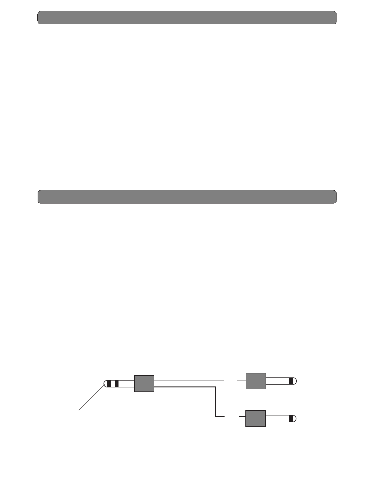
- 4 loop cables (1 stereo to 2 mono jacks).
SEND TO INPUT RETURN TO OUTPUT
GND
INPUT
OUTPUT
Black
Grey

A
B
C
A
B
C
A
B
C
A
B
C
IN
Loads work on the two
systems not selected.
MATRIX FLOW DIAGRAM
Aux Out
Loop
1
Loop
2
Loop
3
Buffer
x1
System
A
System
B
System
C
Input
MATRIX
Mute
Mute
Mute
x1
Buffer
EFX
4
Send
Return
EFX
5
Send
Return
x1
Buffer
A
B
C
Spk out
L & R
From Amp
Head
Power Out
Out to input
amp
head return
Out to input
pre/head
In from
pre/out
head snd
B
C
Foot1 Foot2 Foot3
Aux Out
(Tuner)

INSTRUMENT
HI/Z
SWITCHESLOOPSSYSTEM
A B C MUTE FOOT 1 FOOT 2 FOOT 3 EFX 4 EFX 5 1 2 3
POWER
Matrix
®
MIDI MULTIFUNCTIONS LOOPER/SWITCHER
Guitar / Bass INPUT
These push-buttons allow you to select
the loop/s you prefer. The ones called
FOOT are for foot pedal effects. They
are mono. The ones called EFX are
for rack multieffects. They are stereo.
Y ou can select as many loops as you
want.
These push-buttons
allow you to control
external functions like
channel switching,
bypass and other. You
can select as many
switches as you want.
These push-buttons allow you to select
the system you prefer. Connect the
outputs on the rear pannel to the inputs
of your preamps and/or heads. The
MUTE push-button allows you to
tune your guitar: it is enough to
connect the TUNER output on the
rear pannel to your tuner
LOOPS
OUT TO INPUT PRE/HEAD
C B A
IN FROM PRE OUT/HEAD SEND
C B A
220V-250mAT MADE IN ITALY
IN THRU
MIDI
12V/300mA
MIDIch
A B C
SPEAKER SYSTEM
2x
16
2x
8
9Vdc(max 0,2A)
SPKR Lout
FRM AMP/HEAD POWER OUT
A
mono
B
L
C
L
SWITCHES
3 1
OUT TO INPUT AMP/HEAD RET
C B A
AUX OUT
(TUNER)
FOOT2FOOT3
FOOT1
SWITCHES
EFX5
RET SND RET SND
EFX4
2
FOOT
SND=tip
RET=ring
EFX
LEFT=tip
RIGHT=ring
These jacks are stereo (SND/RET). You
can use the cables supplied with your
Matrix. These loops are for foot pedal
effects only
These jacks are stereo (LEFT/RIGHT).
You can use the cables supplied with
the Matrix . These loops are for rack
effects only.
These jacks are stereo. If you
connect the TIP you will
have N.O. function. On the
contrary if you connect the
RING you will have N.C.
function. These functions are
controlled by relé.
These jack are mono. You
can connect here 1 stereo
speaker cabinet or 2 mono
speaker cabinets. It is
important to connect both the
jacks. Remember to select
the speaker system switch (2
x 16 Ohm or 2 x 8 Ohm).
These jacks are mono. You can use
them to send the signal of your guitar
towards the different systems. The
TUNER output is always active, so
you can use it to tune your guitar or
as a system.
These jacks are mono . You can
use them to receive the signal
coming from the SEND of your
heads, or coming from the
MAIN of your power amps.
The A jack is mono while B and
C are stereo. You can use them to
send the signal towards the
RETURN of your head, or towards
the INPUT of your stereo amps.
Obviously the A system is mono
so it is for heads only.
The MIDI ch dip switch allows you
to select the receiving channel of
program change. Here are the
combinations :
A B C
OMNI off off off
2 on off off
3 off on off
4 on on off
5 off off on
6 on off on
7 off on on
8 on on on
SPKR Rout
C
R
POWER INPUTS
B
R
This phantom power plug
supplies 9 Vdc (200mA max)
for foot pedal effects.
To MIDI store select the combinations on your
Matrix. Then select the preset number on your
footswitch. Press the push-button of the system
selected (A, B, C or MUTE) for few seconds.
The blinking will confirm you the storage.
These jacks are mono.
They switch the power
signal of your heads/amps
towards the speaker
system. A input is mono
while B and C are stereo.
If you use the B and C
loops with mono head
remember to connect both
the B left and B right
inputs, as if you had a
stereo head. Using 2
power cables connect your
head to the 2 inputs
(BL/BR o CL/CR).

LOOPS
OUT TO INPUT PRE/HEAD
C B A
IN FROM PRE OUT/HEAD SEND
C B A
220V-250mAT MADE IN ITALY
IN THRU
MIDI
12V/300mA
MIDIch
A B C
SPEAKER SYSTEM
2x162x
8
9Vdc(max 0,2A)
SPKR Rout
SPKR Lout
POWER INPUTS
FRM AMP/HEAD POWER OUT
A
mono
B
R
B
L
C
R
C
L
SWITCHES
3 1
OUT TO INPUT AMP/HEAD RET
C B A
AUX OUT
(TUNER)
FOOT2FOOT3
FOOT1
SWITCHES
EFX5
RET SND RET SND
EFX4
2
FOOT
SND=tip
RET=ring
EFX
LEFT=tip
RIGHT=ring
SEND
INOUT
supplied cables
9Vdc power cable
8 ohm
Select 2x8ohm
(1 4x12”speaker cabinet)
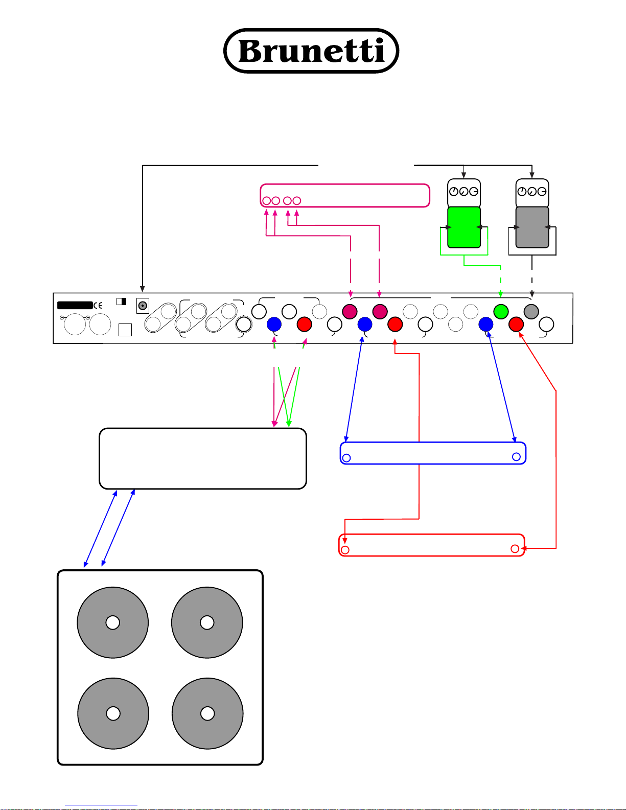
The following examples show you how to connect 2 heads,
1 foot pedal effect, 1 rack effect and 1 4x12” stereo speaker
cabinet 8 ohm
HEAD B
IN
SEND
RETURN
RETURN
IN
HEAD A
SPEAKER OUT
(select 4 ohm)
SPEAKER OUT
(select 16 ohm)
IN
EFX
OUT
LR LR
Remote channels
switching
ATTENTION!!!
Where not written all the jack cables are mono. The power cables have
to be of the correct size.
Remember to connect 2 cables to your 4 x 12” speaker cabinet and
2 cables to the B left and B right (or C left and C right) inputs.
Use always all the POWER INPUTS (left and right) of the chosen systems
(heads or power amplifiers).
Remember to select the speaker system switch on the rear panel: select
8 Ohm stereo for 1 4x12” speaker cabinet; select 16 Ohm for 2 1x12”
speaker cabinets. It is very important to do that to avoid damages to
your equipment.
Every doubt you have do not hesitate to contact us.
(power cables)(power cables)
pag 2
8 ohm
®

LOOPS
OUT TO INPUT PRE/HEAD
C
B A
IN FROM PRE OUT/HEAD SEND
C
B A
220V-250mAT MADE IN ITALY
IN THRU
MIDI
12V/300mA
MIDIch
A B C
SPEAKER SYSTEM
2x162x
8
9Vdc(max 0,2A)
SPKR Rout
SPKR Lout
POWER INPUTS
FRM AMP/HEAD POWER OUT
A
mono
B
R
B
L
C
R
C
L
SWITCHES
3 1
OUT TO INPUT AMP/HEAD RET
C
B A
AUX OUT
(TUNER)
FOOT2FOOT3
FOOT1
SWITCHES
EFX5
RET SND RET SND
EFX4
2
FOOT
SND=tip
RET=ring
EFX
LEFT=tip
RIGHT=ring
SEND
INOUT
Supplied cables
IN
EFX
OUT
LR LR
9Vdc power cable
16 ohm
Select 2x16ohm
(2 1x12”speaker cabinets)
The following examples show you how to connect 2 heads,
1 foot pedal effect, 1 rack effect and 2 1x12” speaker cabinets
16 Ohm
HEAD B
IN
SEND
RETURN
RETURN
SPEAKER OUT
(select 8 ohm)
(stereo jack)
IN
HEAD A
(Power cables) (Power cables)
ATTENTION!!!
Where not written all the jack cables are mono. The power cables have
to be of the correct size.
Remember to connect always 2 1x12” speaker cabinets even if your
head is mono.
Use always all the POWER INPUTS (left and right) of the chosen systems
(heads or power amplifiers).
Remember to select the speaker system switch on the rear panel: select
8 Ohm stereo for 1 4x12” speaker cabinet; select 16 Ohm for 2 1x12”
speaker cabinets. It is very important to do that to avoid damages to your
equipment.
Every doubt you have do not hesitate to contact us.
SPEAKER OUT
select 8 ohm)
pag 3
16 ohm
®

LOOPS
OUT TO INPUT PRE/HEAD
C
B A
IN FROM PRE OUT/HEAD SEND
C
B A
220V-250mAT MADE IN ITALY
IN THRU
MIDI
12V/300mA
MIDIch
A B C
SPEAKER SYSTEM
2x162x
8
9Vdc(max 0,2A)
SPKR Rout
SPKR Lout
POWER INPUTS
FRM AMP/HEAD POWER OUT
A
mono
B
R
C
R
C
L
SWITCHES
3 1
C
B A
AUX OUT
(TUNER)
FOOT2FOOT3
FOOT1
SWITCHES
EFX5
RET SND RET SND
EFX4
2
FOOT
SND=tip
RET=ring
EFX
LEFT=tip
RIGHT=ring
INOUT
8ohm
Select 2x 8ohm
(1 4x12”speaker cabinet)
The following examples show you how to connect 1 heads,1 pre and
power amp, 2 foot pedal effects, 1 rack effect and 1 4x12” stereo
speaker cabinet 8 ohm
INOUT
Supplied cables
9Vdc power cable
PREAMP
IN
OUT
IN
HEAD A
RETURN
SEND
IN
OUT
L R
L R
POWER AMP
IN
EFX
OUT
L R L R
Supplied cables
8ohm 8ohm
(stereo jack)(stereo jack) (stereo jack)(stereo jack)
(Power cables)
B
L
Remote channels
switching
Remote channel
switching
OUT TO INPUT AMP/HEAD RET
ATTENTION!!!
Where not written all the jack cables are mono. The power cables have
to be the correct size.
Remember to connect 2 cables to your 4 x 12” speaker cabinet and
2 cables to the B left and B right (or C left and C right) inputs.
Use always all the POWER INPUTS (left and right) of the chosen systems
(heads or power amplifiers).
Remember to select the speaker system switch on the rear panel: select
8 Ohm stereo for 1 4x12” speaker cabinet; select 16 Ohm for 2 1x12”
speaker cabinets. It is very important to do that to avoid damages to
your equipment.
Every doubt you have do not hesitate to contact us.
(stereo jack)
SPEAKER OUT
(select 16 ohm)
(Power cables)
pag 4
8ohm
®

LOOPS
OUT TO INPUT PRE/HEAD
C
B A
IN FROM PRE OUT/HEAD SEND
C
B A
220V-250mAT MADE IN ITALY
IN THRU
MIDI
12V/300mA
MIDIch
A B C
SPEAKER SYSTEM
2x162x
8
9Vdc(max 0,2A)
SPKR Rout
SPKR Lout
POWER INPUTS
FRM AMP/HEAD POWER OUT
A
mono
B
R
C
R
C
L
SWITCHES
3 1
C
B A
AUX OUT
(TUNER)
FOOT2FOOT3
FOOT1
SWITCHES
EFX5
RET SND RET SND
EFX4
2
FOOT
SND=tip
RET=ring
EFX
LEFT=tip
RIGHT=ring
INOUT
16ohm
The following example show you how to connect 1 head,1preamp
(using the power amp of the head),2 foot pedal efx,1 rack efx,
1 4x12”cabinet
INOUT
supplied cables
9 Vdc power cable
PREAMP
IN
OUT
IN
HEAD A
RETURN
SEND
IN
EFX
OUT
L R L R
supplied cables
(Jack stereo)(Jack stereo) (Jack stereo)(Jack stereo)
B
L
Remote channels
switching
Remote channel
switching
OUT TO INPUT AMP/HEAD RET
ATTENTION!!!
All the cable are mono jack where not specified.
(from jack mono to
2 jack mono)
SPEAKER OUT
(set to 16 ohm)
(Power cable)
pag 5
(Jack stereo)
®
LOOPS
OUT TO INPUT PRE/HEAD
C
B A
IN FROM PRE OUT/HEAD SEND
C
B A
220V-250mAT MADE IN ITALY
IN THRU
MIDI
12V/300mA
MIDIch
A B C
SPEAKER SYSTEM
2x162x
8
9Vdc(max 0,2A)
SPKR Rout
SPKR Lout
POWER INPUTS
FRM AMP/HEAD POWER OUT
A
mono
B
R
C
R
C
L
SWITCHES
3 1
C
B A
AUX OUT
(TUNER)
FOOT2FOOT3
FOOT1
SWITCHES
EFX5
RET SND RET SND
EFX4
2
FOOT
SND=tip
RET=ring
EFX
LEFT=tip
RIGHT=ring
INOUT
The following example show you how to connect 2 preamp,
1 poweramp,2 footpedal efx,1rack efx, 1 stereo cabinet.
INOUT
supplied cables
9 Vdc power cable
PREAMP
IN
OUT
IN
EFX
OUT
L R L R
supplied cables
(Jack stereo)(Jack stereo) (Jack stereo)(Jack stereo)
B
L
OUT TO INPUT AMP/HEAD RET
ATTENZIONE!!!
All the cable are mono jack where not specified
pag 6
IN
PREAMP
OUT
AMP
LINR
From 2 jack stereo (TIP=left/RING=right) to
2 jack mono, with Left (B sys) tied with
Left (C sys). The same for Right side .
L
R
L
R
®

LOOPS
OUT TO INPUT PRE/HEAD
C B A
IN FROM PRE OUT/HEAD SEND
C B A
220V-250mAT MADE IN ITALY
IN THRU
MIDI
12V/300mA
MIDIch
A B C
SPEAKER SYSTEM
2x162x
8
9Vdc(max 0,2A)
SPKR Rout
SPKR Lout
POWER INPUTS
FRM AMP/HEAD POWER OUT
A
mono
B
R
B
L
C
R
C
L
SWITCHES
3 1
OUT TO INPUT AMP/HEAD RET
C B A
AUX OUT
(TUNER)
FOOT2FOOT3
FOOT1
SWITCHES
EFX5
RET SND RET SND
EFX4
2
FOOT
SND=tip
RET=ring
EFX
LEFT=tip
RIGHT=ring
SEND
INOUT
Supplied cables
IN
EFX
OUT
LR LR
9Vdc power cable
Select 2x16ohm
(2 1x12”speaker cabinets)
The following example shows you how to connect 2 heads,
1 foot pedal effect, 1 rack effect and one speakers cabinet
16 Ohm.
HEAD B
IN
SEND
RETURN
SPEAKER OUT
(select 16 ohm)
(stereo jack)
IN
HEAD A
(Power cables)
ATTENTION!!
Where not written all the jack cables are mono. The
power cables have to be of the correct size.
Remember to select the speaker system switch on the
rear panel to “2x16ohm”.Pls connect the power cables
in the “B left” (or “C left”) POWER INPUT.It is very
important to do that to avoid damages to your
equipment.
Every doubt you have do not hesitate to contact us.
SPEAKER OUT
(select 16ohm)
pag 7
16 ohm
(Power cables)
RETURN
®

MODULATION EFFECTS
The main characteristic of the modulation effect (see example) is to add and/or lay other wave forms to the signal.
This kind of effect should be used in the loop effect of your amp, that is between the Premaplifier and the Power
amp.
SYNTHESIS EFFECTS
The main characteristic of the synsthesis effect (see example) is to modify the signal wave form. (i.e. the
distortion effects).
This kind of effect should be used between the guitar and the input of your amp, in a standard connection chain.
SERIAL LOOP
In a Serial Loop all the output signal coming from the Preamp passes throught the effect. In this case on your
effect unit it is necessary to adjust the balance between the DIRECT (DRY) and the EFFECT( WET).
PARALLEL LOOP
In a Parallel Loop only a part of the direct sound passes throught the loop effect, without going out from the
Send. This part of the signal will be mixed with the signal that comes from the Return.
In this connection the quality of the effect is not so important as it is in the Serial Loop connection, because the
Direct will be kept by the loop (see drawing).
PRE
POWER
EFFECT
SEND
RETURN
MIX
DIRECT
EFFECT
SERIAL LOOP
IN OUT
IN
GUITAR
OUT
PRE
EFFECT
SEND
RETURN
MIX
DIRECT
EFFECT
PARALLEL LOOP
IN
OUT
DIRECT
MIX
EFFECT=100%
DIRECT=0%
IN
GUITAR
OUT
To obtain a good sound
we suggest that you set on zero ''0''
the DIRECT (DRY) on the effect.
POWER
Input Signal
Output Signal
OUT
IN
SYNTHESIS
Input Signal
Output Signal
MODULATION
EFX
OUT
IN
EFX
GENERAL INFORMATION

CLEANING
Before any kind of cleaning operation, disconnect the appliance from the electric supply.
- Do not throw water jets directly on the appliance.
- Do not use water steams to clean the appliance.
- Do not use solvents to clean the appliance.
Surface Cleaning: system suggested
Satin Aluminium: Soft cloth + product for metal parts
Stainless steel : Paper + product for chrome parts
WARNINGS
− The manufacturer declines all responsibility for any kind of damage to persons, things and/or
animals resulting from a wrong use of the appliance.
− The appliance' s conformity is proved by CE symbol on the rear side.
− The manufacturer reserves the right to make any useful and essential change to the products
without compromise the main safety and working features.
− Do not use the appliance barefoot.
− Do not touch the appliance with wet or moist hands or feet.
− Do not allow children or incompetents to use the appliance.
− Do not leave inflammable materials near to the appliance.
− Do not pull up the appliance by control knobs.
− Read carefully, compile and deliver the warranty attached to the appliance.
− The appliance' s repair may be done during the warranty period only by us, in our laboratory, or by
authorized staff, in conformity to the national previsions in force.
− Control periodically all cables supplied with the appliance, if they result damaged, you have to replace
them immediately with another one with the same characteristics.
− In case of damage contact the shop where you bought the appliance.
− The appliance must be earthed in conformity to the national previsions in force.
For any further information and/or support contact us.
Brunetti Marco & C. S.a.s
Via Deí Bonomini, 25/27
I - 41100 MODENA - ITALIA
Phone number : +39 059 / 243404
http://www.brunetti.it
e-mail : info@brunetti.it commercial info
e-mail : support@brunetti.it technical info
GENERAL INFORMATION
 Loading...