

Page 1
Brultech Research Inc
1
GreenEye Monitor™ Manual
(Preliminary/Incomplete)
With Pulse Counter and Temperature Sensing Inputs
October 7, 2012
www.brultech.com Copyright © 2012 Brultech Research Inc. All rights reserved.
Energy Consumption Monitor
Page 2

Brultech Research Inc
2
Introduction ........................................................................................................................................................................... 4
Overview ................................................................................................................................................................................... 4
The sensors ................................................................................................................................................................................ 6
Current Sensors .................................................................................................................................................................... 6
Voltage Sensors .................................................................................................................................................................... 6
Pulse Output Devices ............................................................................................................................................................ 6
Temperature Sensors ........................................................................................................................................................... 6
Communication ......................................................................................................................................................................... 7
Where to Start ....................................................................................................................................................................... 8
Read and UNDERSTAND the safety information ....................................................................................................................... 8
Power up and establish communication before installing ........................................................................................................ 8
Plan the mounting location for the monitor, taking into consideration the CT lead length ..................................................... 8
Important Safety Information .............................................................................................................................................. 10
Compliance .......................................................................................................................................................................... 11
Overview / Layout ............................................................................................................................................................... 12
(1) CT Connection Terminals ................................................................................................................................................... 13
(2) Pulse Counter Inputs .......................................................................................................................................................... 13
(3) Potential Transformer (PT) Input ....................................................................................................................................... 14
(4) Alternate Potential Transformer (PT) And 5VDC Supply Input .......................................................................................... 14
(5) GEM Power Supply Input ................................................................................................................................................... 14
(6) Power Supply Access Terminals ......................................................................................................................................... 14
(7) “1-Wire” Bus and RS-232 Ground Terminal ....................................................................................................................... 14
(8) RS-232 Connection ............................................................................................................................................................. 14
(9) Optional COM Module Header .......................................................................................................................................... 14
(10) Optional WiFi Module ...................................................................................................................................................... 15
(11) XBee® Module Socket ...................................................................................................................................................... 15
(12) Battery Holder .................................................................................................................................................................. 15
(13) System and Communication LEDs .................................................................................................................................... 15
(14) Push Button Switch .......................................................................................................................................................... 15
Current Transformer (CT) Installation .................................................................................................................................. 17
Important ................................................................................................................................................................................ 17
Type A CT Connection ............................................................................................................................................................. 19
Single CT Connection .......................................................................................................................................................... 19
Dual Type A CT Connections ............................................................................................................................................... 19
Type B CT Connection .............................................................................................................................................................. 20
Single CT Connection .......................................................................................................................................................... 20
Dual Type B CT Connections ............................................................................................................................................... 20
Pulse Count Inputs ............................................................................................................................................................... 22
Potential Transformer (PT) Input ......................................................................................................................................... 23
3.5mm Phone Jack .............................................................................................................................................................. 23
Mini USB Jack ...................................................................................................................................................................... 24
Power Supply Input .............................................................................................................................................................. 25
Power Supply Access Terminal Block ...................................................................................................................................... 25
CT Installation ...................................................................................................................................................................... 26
Single/Split Phase Residential System ..................................................................................................................................... 27
Three Phase (Polyphase) 4-Wire Wye(Y) System .................................................................................................................... 28
CT Connection (Four-Wire WYE System) ............................................................................................................................ 30
Displayed Polarity ............................................................................................................................................................... 30
October 7, 2012
www.brultech.com Copyright © 2012 Brultech Research Inc. All rights reserved.
Page 3

Brultech Research Inc
3
Three Phase (Polyphase) 3-Wire Delta (∆) System .................................................................................................................. 31
Communication Link ............................................................................................................................................................ 32
COM Ports ............................................................................................................................................................................... 32
COM Port Bridge Mode ........................................................................................................................................................... 34
RS-232 Port .............................................................................................................................................................................. 36
WiFi Communication Option ................................................................................................................................................... 36
XBee® Module Option ............................................................................................................................................................. 37
Ethernet Module Option ......................................................................................................................................................... 37
Combination WiFi/Ethernet Option ............................................................................................ Error! Bookmark not defined.
Custom Com PCB Header ........................................................................................................................................................ 37
Firmware Upgrades .............................................................................................................................................................. 38
COM Processor Firmware Upgrade ......................................................................................................................................... 38
Recovering From Corrupt COM Firmware ............................................................................................................................... 41
ENG Processor Firmware Upgrade .......................................................................................................................................... 41
Recovering From Corrupt ENG Firmware ................................................................................................................................ 42
Technical Specification ......................................................................................................................................................... 43
Power Metering ....................................................................................................................................................................... 43
Pulse Counting ......................................................................................................................................................................... 44
Temperature Sensing .............................................................................................................................................................. 45
Communication ....................................................................................................................................................................... 45
GEM System ............................................................................................................................................................................ 46
Channel Assignment Worksheet .......................................................................................................................................... 48
October 7, 2012
www.brultech.com Copyright © 2012 Brultech Research Inc. All rights reserved.
Page 4
Brultech Research Inc
4
Introduction
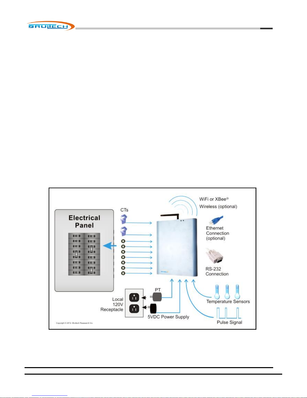
The GREENEYE MONITOR (GEM) Home Energy Monitor is a multi-channel power meter designed to measure the
consumption of residential service panels and/or panel circuits. The measured data is then transferred to a computer or
internet server for storage, analysis and real-time display.
The primary function of the GEM is to monitor electrical energy consumed. Additional inputs have been included to measure
other consumables such as water, gas and propane, providing there is a pulse signal available from such devices. The GEM
also provides a “1-Wire Bus” which accepts low cost sensors to monitor temperature from various rooms and outdoors.
The GEM processes all of the measured data then sends it to a host computer, server or website for display and analysis.
Overview
The basic function of the GEM is to:
1. Read and convert the sensor signals to real-world values.
2. Process the acquired metrics.
3. Forward the data to a host for access via computer, internet, automation system or smart phone.
NOTE: Only low voltage, galvanic isolated signals are connected to the GreenEye™ Monitor!
October 7, 2012
www.brultech.com Copyright © 2012 Brultech Research Inc. All rights reserved.
Page 5

Brultech Research Inc
5
The current sensors (CT) are small non obtrusive devices installed in the electrical panel on each circuit breaker circuit. Two
larger CTs are installed on the power feed from the Utility Company, providing total house consumption. Optionally, other
sensors may be connected to provide temperature or water/gas consumption.
Two supplies are used, one +5V supply to power the GEM and the second to monitor the power line voltage for accurate true
power conversion.
The GEM converts the data from the sensors and makes it available to a host. The host could be one or more of the following:
A website dedicated to monitoring, displaying and charting consumption information.
A local web server. We have available, a small powerful web server which consumes less than 5Watt to operate
(That’s less than 2 cents per day)
Personal website.
Local PC
Home automation system
Smart phone via one of the above options
Your own custom solution. We provide API information upon request.
There is a variety of options available for communication depending on the server option chosen and wireless range. The
communication options are:
Two RS-232 COM ports via push terminal block
Wifi communication (optional)
Ethernet connection (optional)
XBee® Module for ZigBee® communication (optional)
October 7, 2012
www.brultech.com Copyright © 2012 Brultech Research Inc. All rights reserved.
Page 6

Brultech Research Inc
6
The sensors
Various sensors may be used with the GEM:
Current Sensors
Voltage Sensor
Pulse Output Devices
Temperature Sensors
Current Sensors
Current sensing is done using “current transformers” referred to as “CT”
throughout this manual. The CTs we use require no electrical connection since the
sensed electrical current is accomplished by reading the magnetic field of an electrical conductor.
Voltage Sensors
The powerline voltage needs to be measured in order to calculate “true power”. This is
accomplished using a single “potential transformer” referred to as “PT” throughout this
manual. The “powerline voltage” is the voltage present at the electrical receptacle, typically
120V or 240V depending on the Country. The PT isolates this voltage and reduces it to a safe
low voltage value for the GEM to monitor.
Pulse Output Devices
Some water, gas and propane meters provide a “pulse output”. This is a simply ON-OFF signal which
occurs any time an “x” amount of a given consumable is used. For example a water meter could provide a
single on-off pulse for each gallon used. These pulses are accumulated by the GEM to provide the amount
and time of consumption. If the meter does not provide a pulse signal then one can be added to existing
water, gas or other system. (Check with local utility company for rules and codes!)
The picture on the right shows a typical water meter with pulse output available from
http://www.temcocontrols.com
Temperature Sensors
The GEM uses a “1-Wire®” bus for temperature sensing and is based on the Maxim/Dallas
DS18B20 sensors. These sensors can share a common 3-conductor cable.
The picture on the right shows a typical temperature sensor available from
http://www.adafruit.com
October 7, 2012
www.brultech.com Copyright © 2012 Brultech Research Inc. All rights reserved.
Page 7

Brultech Research Inc
7
Communication
The GEM offers a multitude of communication options to transfer the monitored data to its destination. Two separate
ports each providing various communication options are provided:
1. RS-232
2. WiFi (optional) *will soon be discontinued due to erratic performance of Roving Networks’ RN-171 WiFly Module.
3. Ethernet (optional)
4. Combination WiFi and Ethernet module (optional) *recommended
5. ZigBee® via XBee® modules from Digi.com (optional)
6. A PCB header for custom options
October 7, 2012
www.brultech.com Copyright © 2012 Brultech Research Inc. All rights reserved.
Page 8
Brultech Research Inc
8
Where to Start
It is very important to plan the installation of the GreenEye Monitor (GEM). The guide below will help ensure a smooth
installation.
Read and UNDERSTAND the safety information
This is the most important step! Not only will this help ensure that the installation will be according to local codes,
but will also prevent injury, fire or fatality.
Power up and establish communication before installing
This mainly applies to systems using WiFi or ZigBee® wireless communication. It is recommended to simply power up
the GEM (without any sensors connected) while in close range to the WiFi router or ZigBee® coordinator whichever
applies, and configure the SSID, IP address, etc. This will help decipher any possible range issues if there are
problems with the wireless connection.
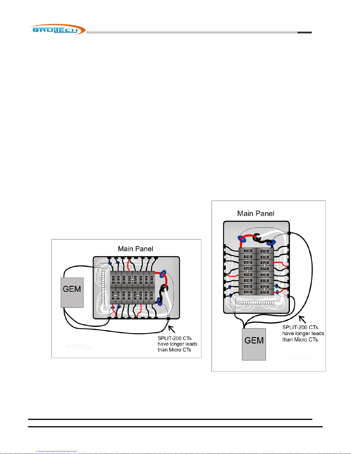
Plan the mounting location for the monitor, taking into consideration the CT lead length
It is important to consider where the CT leads will be routed when
choosing a location to mount the GEM. If mounted to far away, the
CT leads may not reach the terminal strips. The best location is
usually as shown in the pictures below:
1.
October 7, 2012
www.brultech.com Copyright © 2012 Brultech Research Inc. All rights reserved.
Page 9
Brultech Research Inc
9
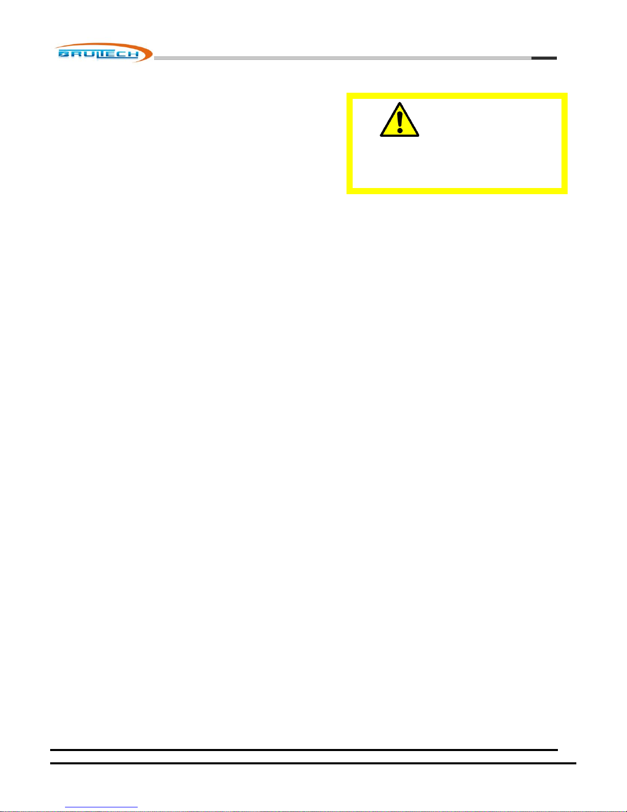
WARNING !
NEVER Install The GREENEYE MONITOR
(GEM) Unit Inside the Electrical Panel
Identify the mounting area for the GREENEYE MONITOR (GEM)
Identify the breaker panel circuits you will be monitoring.
Occasionally, circuit breakers are improperly identified. Switch the
breaker off to verify that it indeed kills the power to the load in
question.
Any GREENEYE MONITOR (GEM) input which will host more than one CT requires special attention so that the CT is installed
with proper orientation. This is explained later in this chapter.
The diagram below illustrates a very simple installation. Typically, the installation will involve using more current sensors to
measure as many electrical loads as possible.
October 7, 2012
www.brultech.com Copyright © 2012 Brultech Research Inc. All rights reserved.
Page 10

Brultech Research Inc
10
WARNING !
Read All Of The Safety Rules Before
Installing!
Important Safety Information
The GREENEYE MONITOR (GEM) operates as a “Class II” low voltage
device. This requires that all external connected signals be a low voltage
(<50V) and provided by Class II approved power supply and sensors.
All of our power supplies are UL, CSA or UL/c approved for use in USA and
Canada. Most of our current transformers (CT) are UL/c listed. No direct
line connections to the GEM are allowed. All signals must be galvanic
isolated from the power-line.
Never install the GEM inside an electrical panel. A separate “low voltage” panel may be used when
needed.
The GREENEYE MONITOR (GEM) installation requires the installation of current transformers (CT)
installed inside the electrical service panel. This portion of the installation MUST be performed by a qualified electrician or
individual. The installer must follow all local safety codes and use proper safety practices and equipment.
The qualified installer must be aware that main panels may still contain dangerous voltage levels even though the main
breaker is in the “OFF” position.
The following rules MUST be obeyed!
Any work performed inside the electrical panel must be done by an electrician or qualified individual. This
individual will be familiar with the local electrical code and perform the installation accordingly.
NEVER install the GreenEye Monitor (GEM) inside the electrical panel. Only low voltage (12VAC or less) galvanic
isolated connections are to be made to the GREENEYE MONITOR (GEM) terminals.
The current transformer (CT) leads must exit the electrical panel through an appropriate box connector, strain
relief or bushing. The CT leads must be properly anchored on the outside of the panel.
The portion of the CT leads inside the panel must not have any damage, cuts or wear to the outside insulation.
The CT leads must be routed in such a way that its insulation will not be rubbing against live terminals. Care must
be exercised not to pinch the CT leads especially when re-installing the panel cover.
Do not install the CTs in panels with voltages greater than 300V.
Do not install the GREENEYE MONITOR (GEM) in a wet location.
October 7, 2012
www.brultech.com Copyright © 2012 Brultech Research Inc. All rights reserved.
Page 11

Brultech Research Inc
11
Compliance
The GreenEye Monitor models GEM-W and GEM-E have been Tested to Comply with FCC Standards
For Home and Office Use.
This device complies with Part 15 of the FCC Rules. Operation is subject to the following two
conditions:
(1) this device may not cause harmful interference, and
(2) this device must accept any interference received, including interference that may cause undesired operation.
Wireless Versions:
Contains FCC ID: OUR-XBEE2 (USA) (Wireless Versions Only)
Contains Model XBee® ZNet 2.5 Radio, IC: 4214A-XBEE2 (Canada)
May Contain Roving Networks WiFly Module FCC ID: T9J-RN171
May Contain FCC ID: AZYHF-A111
October 7, 2012
www.brultech.com Copyright © 2012 Brultech Research Inc. All rights reserved.
Page 12
Brultech Research Inc
12
Overview / Layout
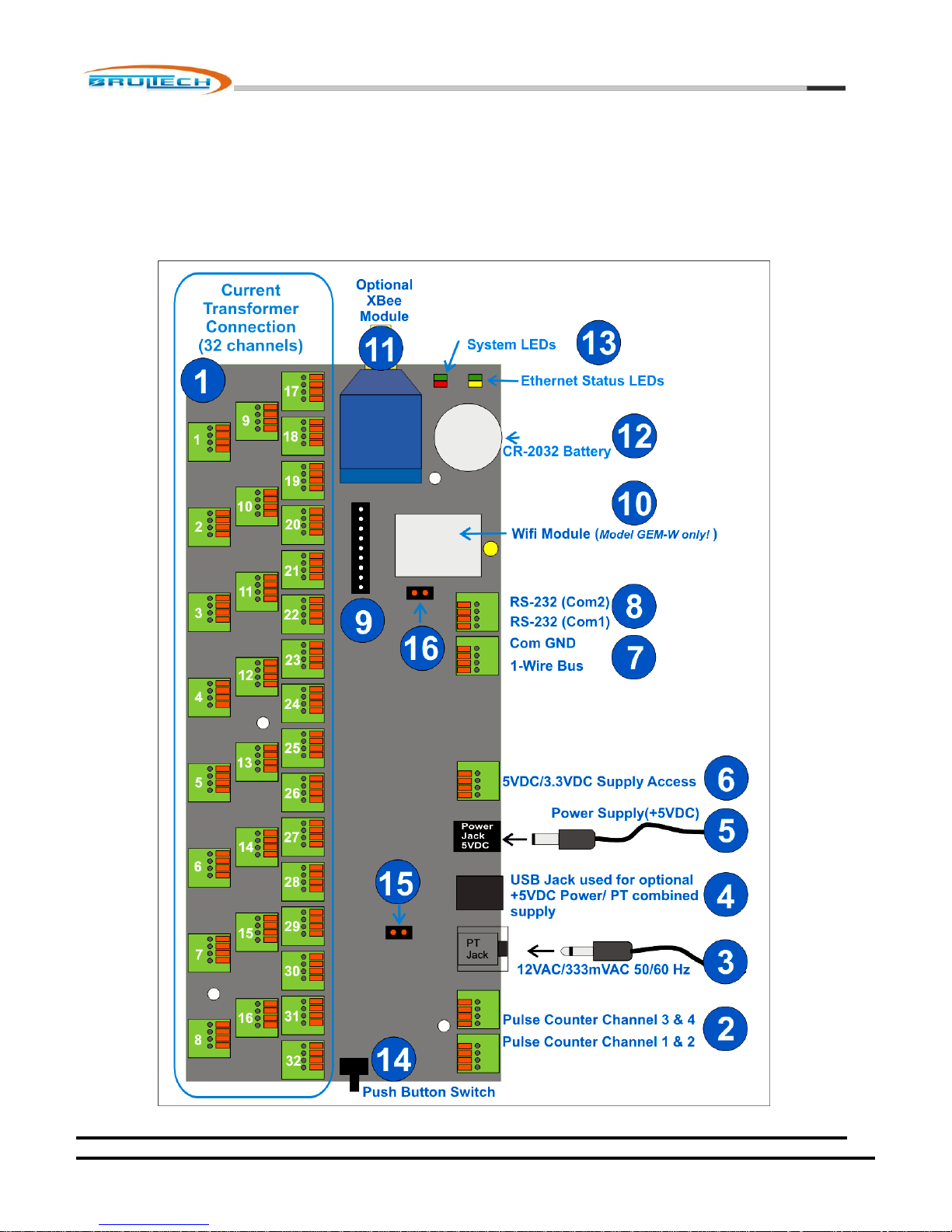
The diagram below illustrates various items and sections of the GEM circuit board. This chapter describes each numbered
section.
October 7, 2012
www.brultech.com Copyright © 2012 Brultech Research Inc. All rights reserved.
Page 13
13
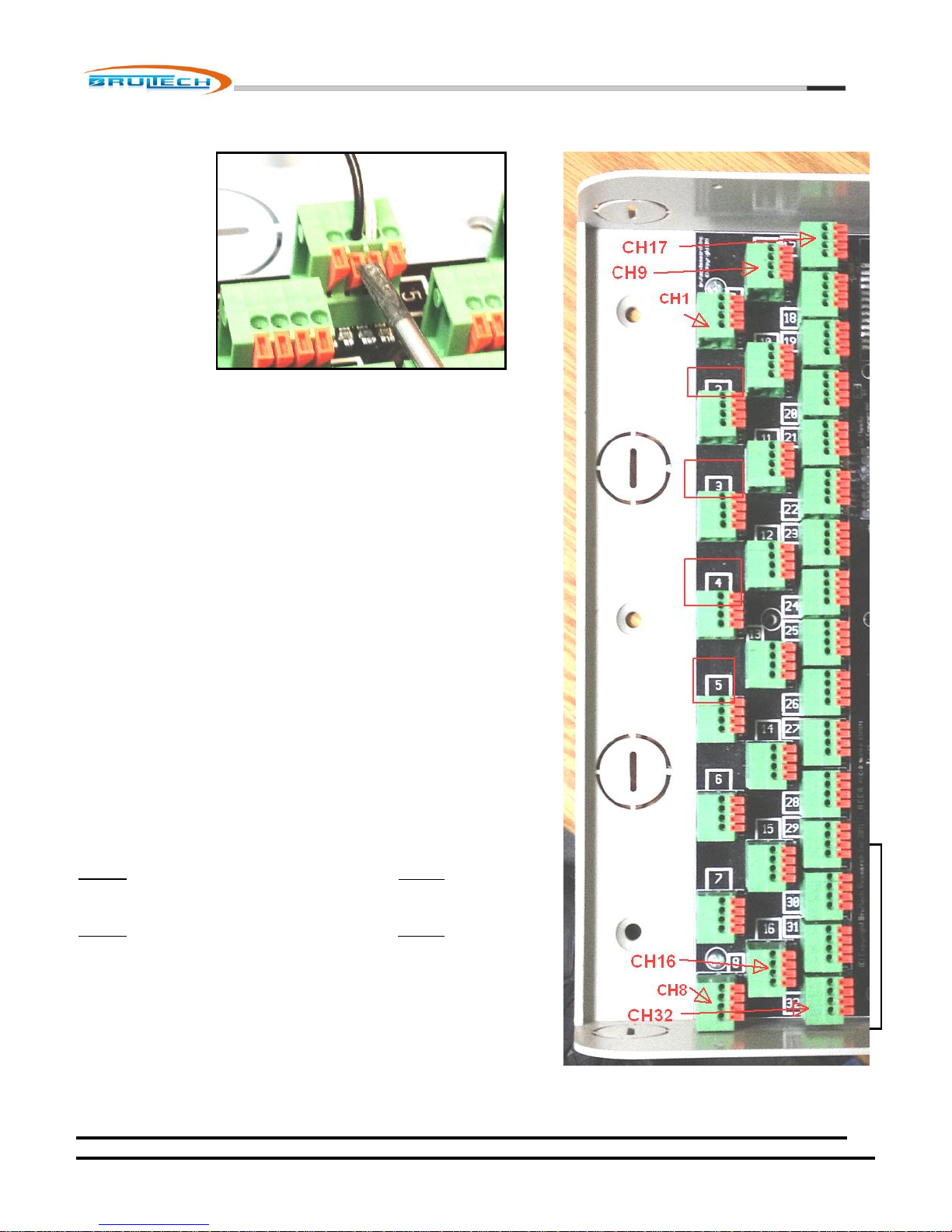
(1) CT Connection Terminals
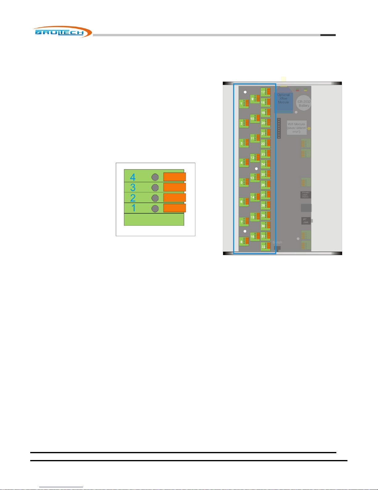
This section is composed of 32 terminal blocks, one for each of
the power monitoring channels. The channel number is printed
on the circuit board.
The terminal blocks have four terminals each. This is where the
CT leads connect to the GEM
The terminals are numbered 1-4, although not marked directly
on the terminal block. The legend below should be used as a
guide.
The terminal number to be used will vary based on the “Type”
of the CT and the number of CTs connected to a given channel.
IMPORTANT! The CT leads must be stripped back 10mm for proper connection to the terminal block. See
“Connecting CT to the terminal blocks” section.
Brultech Research Inc
(2) Pulse Counter Inputs
The GEM has four pulse counting inputs. Pulse signals may be acquired from certain water, gas or electric meters to
indicate the amount of consumption.
Pulse channels 1 and 2 are designed to accept voltage pulses and channels 3 and 4 are pulsed using “dry” contact
closure.
See “Pulse Counting” section.
October 7, 2012
www.brultech.com Copyright © 2012 Brultech Research Inc. All rights reserved.
Page 14

Brultech Research Inc
14
(3) Potential Transformer (PT) Input
The GEM may receive the PT signal from the 3.5mm phone jack (#3) or via the mini USB connector (#4). The 3.5mm
jack is a stereo style jack providing two voltage range options, depending on the PT used. See “PT” section for more
information.
(4) Alternate Potential Transformer (PT) And 5VDC Supply Input
NOTE: This is not a standard USB port for communication.
This mini USB jack may be used as an alternative to the 3.5mm jack (#3), providing the PT signal is in the 333mVAC
(.333V) range. This USB jack us dual duty and may also provide an alternative to the +5 Volt DC power supply jack
(#5).
(5) GEM Power Supply Input
This 2.1mm X 5.5mm barrel jack is for the 5VDC supply connection. The center pin is the (+) positive connection.
(6) Power Supply Access Terminals
This four terminal block provides access to the GEM’s +5V and +3.3V supply. This is reserved for future options and
special applications.
(7) “1-Wire” Bus and RS-232 Ground Terminal
This four terminal block possessed the three connections for the “1-Wire” bus and also the “Common Ground”
connection for the RS-232 connection (#8).
(8) RS-232 Connection
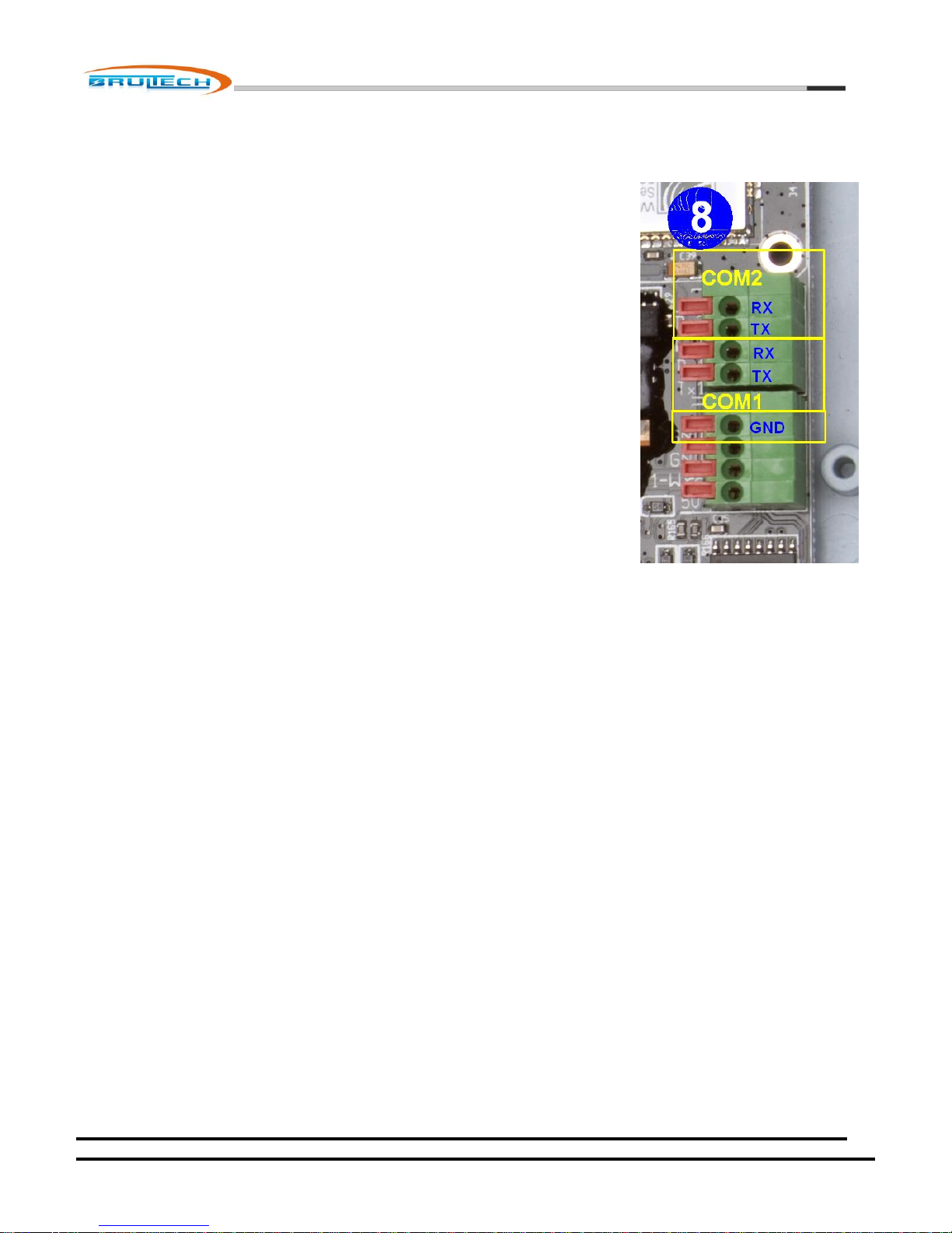
This four terminal block encompasses the receive (RX) and transmit (TX) lines for both RS-232 COM ports.
(9) Optional COM Module Header
This 10-pin 2mm pitch header provides access to the UART and power supply providing an interface for alternate
communication modules. This header should only be used with available modules. Please contact Brultech if you
wish to design a custom communication interface using this header.
October 7, 2012
www.brultech.com Copyright © 2012 Brultech Research Inc. All rights reserved.
Page 15

15
(10) Optional WiFi Module
The model “GEM-W” includes a WiFi communication module.
(11) XBee® Module Socket
The GEM may be fitted with Digi’s XBee® or XBee®-Pro modules providing ZigBee® communications. An opening is
also included in the enclosure in should a module with external antenna is used.
(12) Battery Holder
A CR-2032 battery is used to retain data under power outage conditions.
(13) System and Communication LEDs
The left tri-color LED is used for “System Status”.
The two color LED on the right side provides Wifi status if this option is present or other status depending on the
Ethernet option included.
Brultech Research Inc
(14) Push Button Switch
The push button switch stem is accessible from outside the enclosure. The purpose of this switch is to provide some
optional settings when a communication link is not yet configured or available.
This switch is also used for exiting bridge mode. Anytime the communication is put into bridge mode which couples
Com1 communication to Com2, any press of the switch causes the GEM to exit bridge mode.
The switch is also used to recover from situations where communication is lost while upgrading the “COM”
processor’s firmware thereby corruption the firmware. The push button switch is then pressed while power to the
GEM is cycle allowing a fresh start to upgrading the firmware. Please follow the appropriate instructions with the
setup program before attempting this.
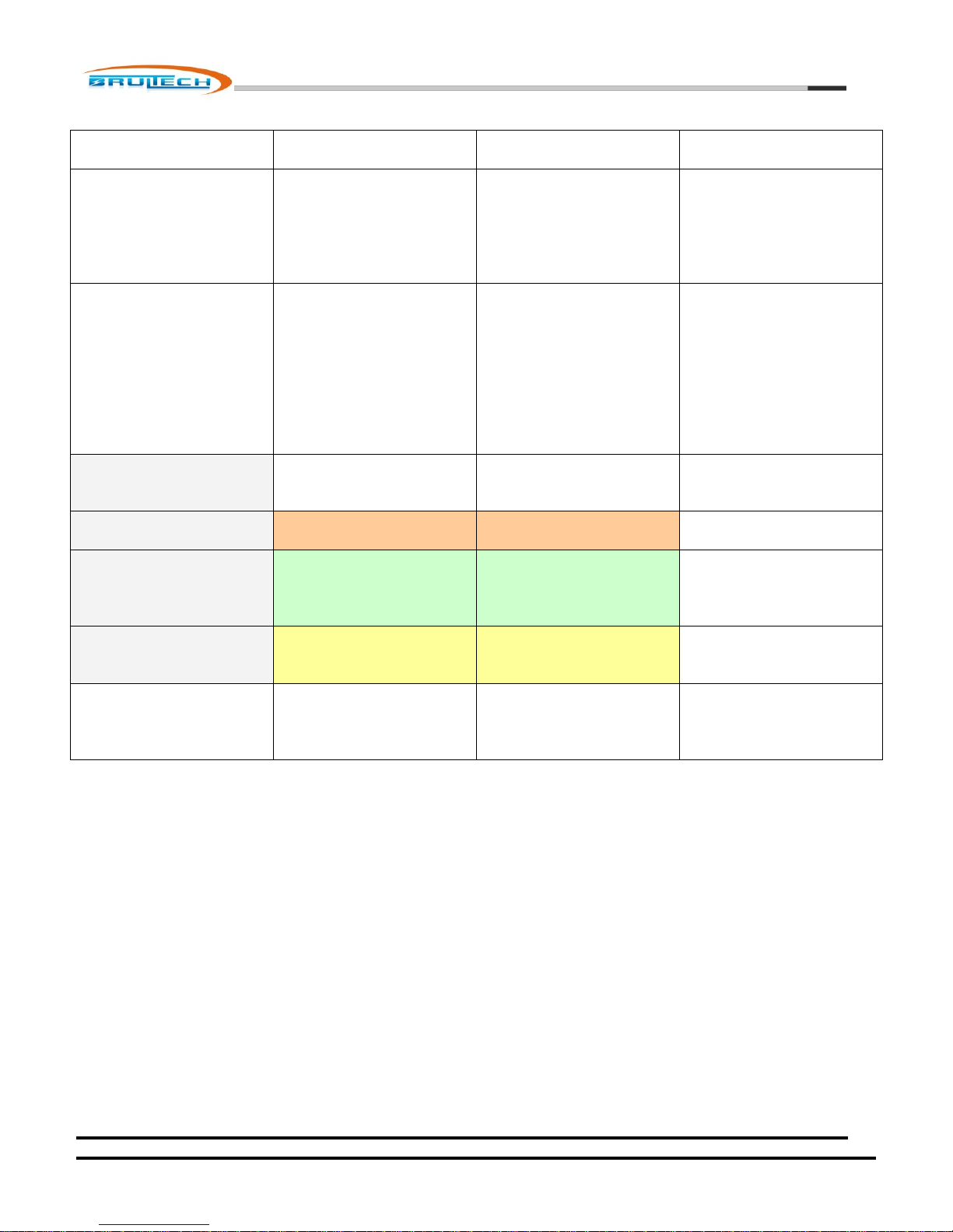
There are two set of three functions available. Each set is entered using a specific key sequence. Once the sequence
has been executed and the push button has been released, the “system” LED will generate the following sequence:
Flash RED three times (function 1 option), then
Flash GREEN three times (function 2 option), then
Flash YELLOW three times (function 3 option), then exit the sequence and return to normal
operating mode.
If the switch is briefly pressed during any of the flashing sequences, the option relating to the corresponding color
will execute. For example, if the switch is momentarily pressed during the “green” sequence, the GEM will execute
the “green option”.
As mentioned before, there are two set of functions. Each set is entered by executing a unique key sequence.
The WiFi function is entered by pressing the switch and holding in ON for 6 seconds. Once the switch is released, the
LEDs will perform the flash sequence as detailed above; green, red and yellow each flash three times in a row.
October 7, 2012
www.brultech.com Copyright © 2012 Brultech Research Inc. All rights reserved.
Page 16
Brultech Research Inc
16
Options 1
Options 2
Push Button
Sequence Required
to Enter Option
Press PB switch for 5
seconds then release
Press PB briefly four
times in a row at 1
seconds intervals. (The
red LED should come
on each press)
System LED Flash
Sequence
Red three times
Green three
times
Yellow three
times
Return to
normal
operation
Red three times
Green three
times
Yellow three
times
Return to
normal
operation
FUNCTION if PB
pressed while
flashing:
Red
WiFi Adhoc Mode for
initial setup
Not yet defined
Green
Recall “user2” Settings
Send AT command to
XBee® Module to
search for ZigBee®
PAN. (ATNR0)
Yellow
Recall “user3” Settings
Send “reset” (reboot)
to WiFi and XBee®
modules.
FUNCTION if PB is
NOT pressed during
the flashing
sequence
Return to normal
operation
Return to normal
operation
October 7, 2012
www.brultech.com Copyright © 2012 Brultech Research Inc. All rights reserved.
Page 17
Brultech Research Inc
17
Current Transformer (CT) Installation
Important
The current transformers are installed inside the electrical panel. The CTs MUST be
installed by a qualified individual. Read the “Safety” section at the beginning of this
document!
CT Connection to the Terminal Strip
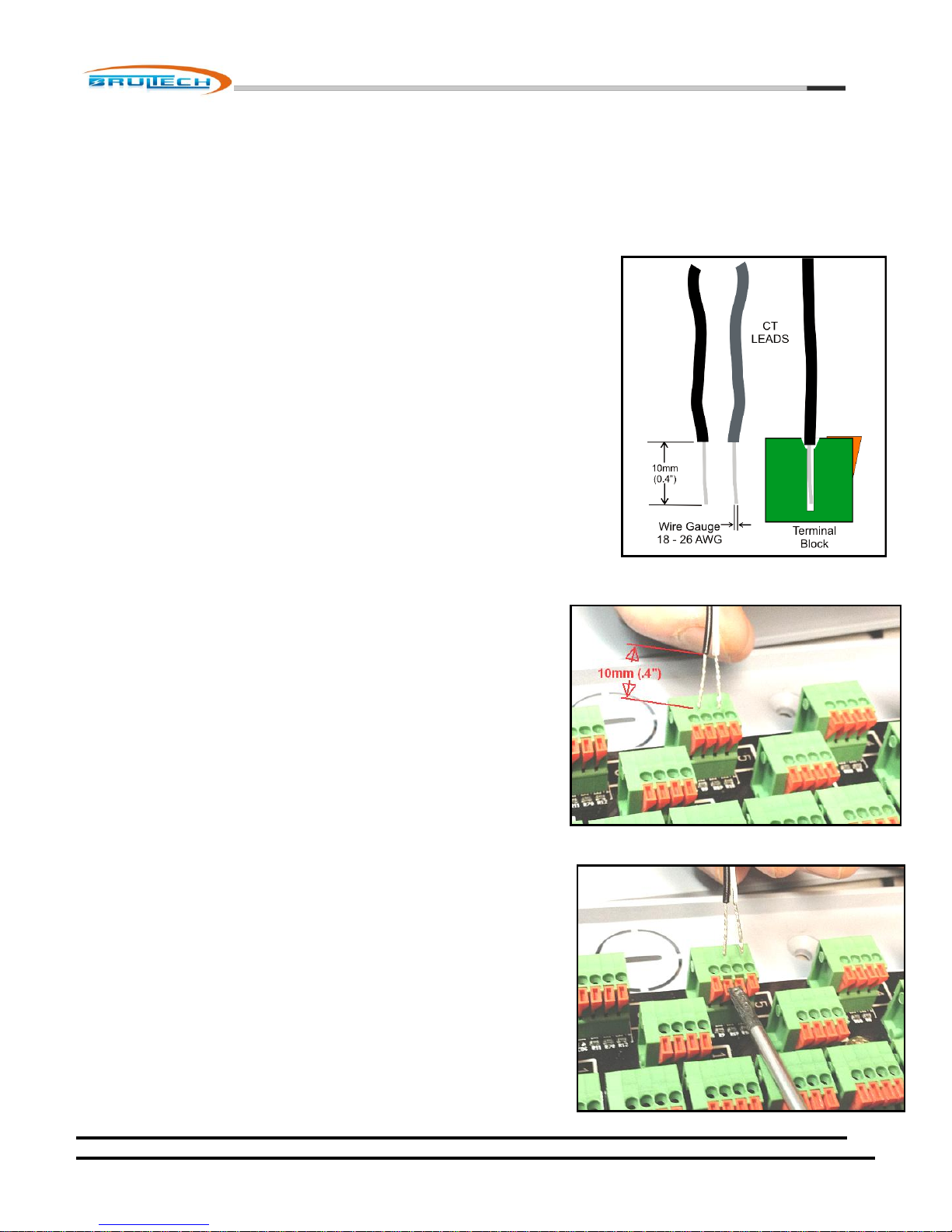
NOTE: The CT leads must be stripped approximately 10mm (0.4”) and have a
gauge size between 18 and 26 AWG.
The GEM uses spring loaded terminal blocks. The CT leads must be stripped the
proper length. If the leads have stranded wire, it is preferable to “tin” the wire
before hand to prevent dealing with frayed ends. (Tinning is the process of adding
solder to bond all of the strands together).
Connecting the CT leads to the terminal strip
1. Align the two lead ends with the terminal holes. This can be done
one lead at a time, however its seems to be easier inserting both
leads at the same time, providing they are nicely tinned with no
frayed ends.
2. Press down on the orange TAB(s) corresponding to the lead or
leads to be inserted, using a small “flat blade” screwdriver.
October 7, 2012
www.brultech.com Copyright © 2012 Brultech Research Inc. All rights reserved.
Page 18
Brultech Research Inc
18
3. Insert the leads into the terminal block while making sure the
leads are perpendicular. In most cases, both CT leads can be
inserted at the same time. If the lead was stripped back 10mm,
then the stripped section should be entirely inside the block with
only the insulation visible.
4. Release the pressure to the spring tab.
5. Finally, tug slightly on the leads to make sure they are secure.
The channel number for each block is printed on the circuit board next to
each terminal block as shown in the picture (right).
IMPORTANT!
Two types of current transformers are compatible with the GEM, Types
A and B.
The difference between each type has to do with the type of signal which
represents the sensed current:
TYPE A: The measured current is represented by a voltage output signal.
(SPLIT-60, SPLIT-100, SPLIT-200, SPLIT-400)
TYPE B: The measured current is represented by a current output signal.
(Micro-40, Micro-80, Micro-100, SPLIT-170)
Because of this difference, each CT type has to be connected to the
terminal strip of the GEM in a different manner.
October 7, 2012
www.brultech.com Copyright © 2012 Brultech Research Inc. All rights reserved.
Page 19
Brultech Research Inc
19
Type A CT Connection
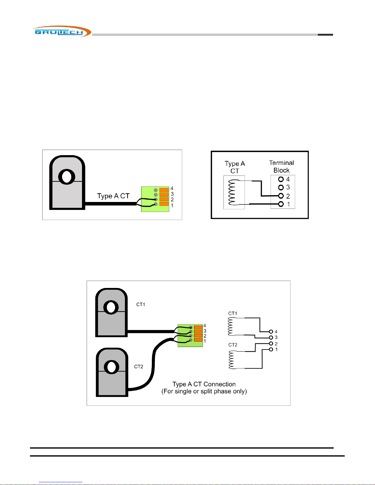
Again, what constitutes a “Type A” CT is the fact that the signal produced is a voltage, usually below 0.333V.
Single CT Connection
Type A CT leads connects to terminals 1 and 2. This applies for any single “Type A” CT. When a single CT is connected to a
channel, the lead polarity (lead color code) does not matter.
Dual Type A CT Connections
This technique for coupling two CTs on a single channel only applies to single or split-phase services. This cannot be done
with 3-phase systems, unless the 2nd CT is monitoring another load located on the same phase. See 3-phase section for more
information.
October 7, 2012
www.brultech.com Copyright © 2012 Brultech Research Inc. All rights reserved.
Page 20
Brultech Research Inc
20
Both CTs must be of the same model. For example although SPLIT-100 and SPLIT-200 CTs are both Type A CTs, they may no
be combined on a single channel.
It is important to pay attention to the lead polarity when more than one CT is connected to a single channel. If a mistake is
made with regards to lead polarity, there will be no harm or damage as a result. The consequence of this is that the current
from one CT will be subtracted from the other. For example:
CT1 monitors a 60W load and CT2 monitors a 100W load. Improper polarity will cause the GEM to display this as a
40W load instead of 160W which is the sum of both loads.
It is very easy to correct such a situation. Remove the leads of one CT only and swap the two leads….. insert the black wire
where the white wire was previously and vice versa.
Sometimes it is just as easy to take the 50/50 chance a make a quick check by simply disconnecting one of the CT leads while
observing the power (watt). If the power increases when the CT lead is removed, then simply swap the polarity on one CT
only. This should result in an increase in power (providing there is a load on this circuit).
Type B CT Connection
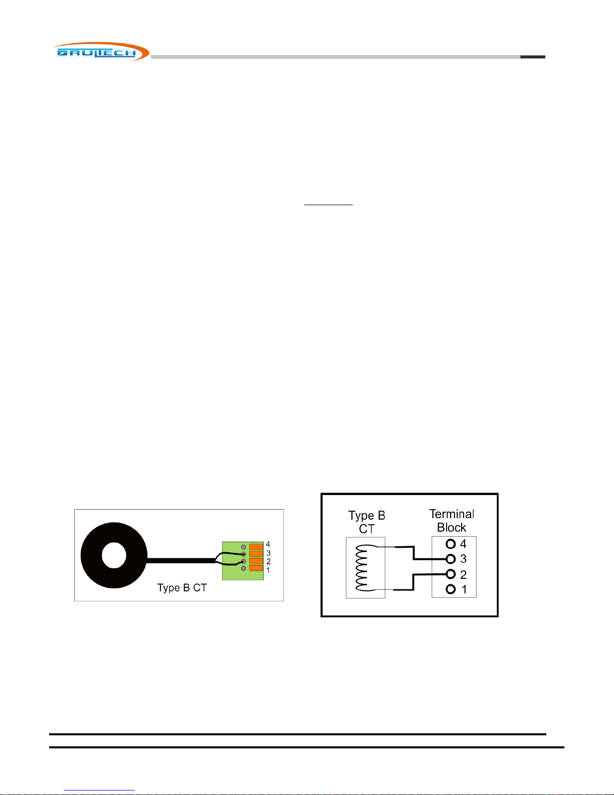
Again, what constitutes a “Type B” CT is the fact that the signal produced is a current signal, usually in the milliamp (mA)
range.
Single CT Connection
Type B CT leads connect to terminals 2 and 3. When only one CT is connected to a given channel, the lead polarity does not
matter.
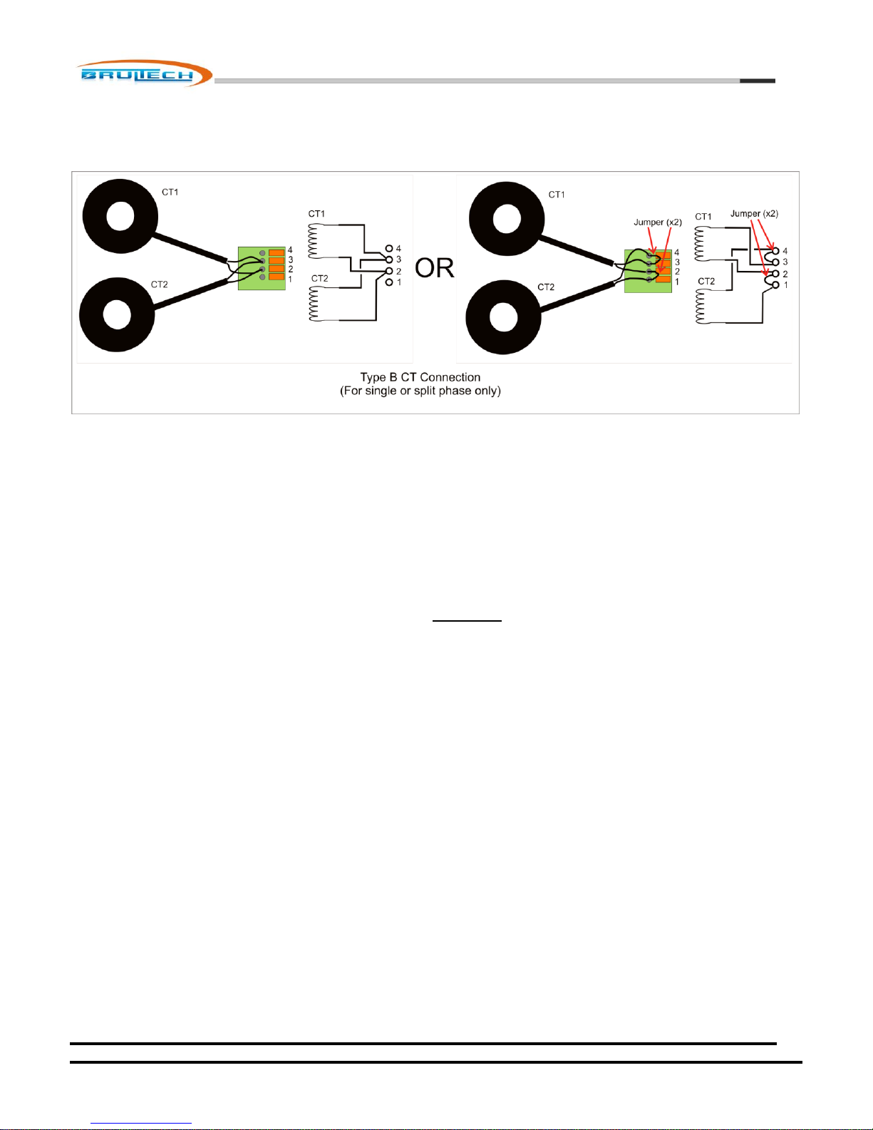
Dual Type B CT Connections
This technique for coupling two CTs on a single channel only applies to single or split-phase services. This cannot be done
with 3-phase systems, unless the 2nd CT is monitoring another load located on the same phase. See 3-phase section for more
information.
October 7, 2012
www.brultech.com Copyright © 2012 Brultech Research Inc. All rights reserved.
Page 21
Brultech Research Inc
21
Both CTs must be of the same model. For example although Micro-100 and Micro-40 CTs are both Type B CTs, they may no be
combined on a single channel.
It is important to pay attention to the lead polarity when more than one CT is connected to a single channel. If a mistake is
made with regards to lead polarity, there will be no harm or damage as a result. The consequence of this is that the current
from one CT will be subtracted from the other. For example:
CT1 monitors a 60W load and CT2 monitors a 100W load. Improper polarity will cause the GEM to display this as a
40W load instead of 160W which is the sum of both loads.
It is very easy to correct such a situation. Remove the leads of one CT only and swap the two leads….. insert the black wire
where the white wire was previously and vice versa.
Sometimes it is just as easy to take the 50/50 chance a make a quick check by simply disconnecting one of the CT leads while
observing the power (watt). If the power increases when the CT lead is removed, then simply swap the polarity on one CT
only. This should result in an increase in power (providing there is a load on this circuit).
October 7, 2012
www.brultech.com Copyright © 2012 Brultech Research Inc. All rights reserved.
Page 22
Brultech Research Inc
22
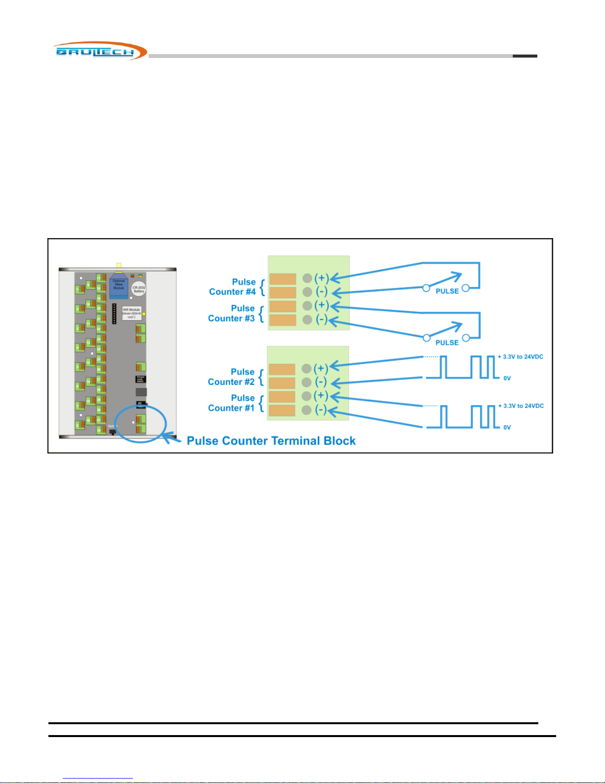
Pulse Count Inputs
The GEM has four pulse count inputs. Pulse counter #1 and #2 are totally isolated from the GEM ground and circuit. Either of
these two inputs require a DC pulse signal between 3V and 24VDC.
Pulse counters #3 and #4 are “dry” contact type counters. These inputs require switch contacts not connected to any power
source, such as relay contacts or magnet switch contacts. Very low voltage from the circuit (5VDC) is used to complete the
circuit.
October 7, 2012
www.brultech.com Copyright © 2012 Brultech Research Inc. All rights reserved.
Page 23
Brultech Research Inc
23
Potential Transformer (PT) Input
The potential transformer is responsible for providing a low voltage image of the line voltage to the GEM for accurate true
power calculations. This signal must be galvanic isolated to maintain safe low voltage to the GEM.
A 120VAC to 12VAC UL/CSA wall transformer (North America) is used as a potential transformer and is included in the GEM
package. Since the step down ratio is not identical for all wall transformers of the same model, the PT Type setting may
altered slightly to improve voltage accuracy. This requires a true RMS DMM connected to the line voltage as a reference.
The PT Type value is increased or decreased slightly until the voltage displayed by the GEM, matches the voltage at the outlet
where the PT is connected.
CAUTION!
Only galvanic isolated low voltage (<14VAC) PT certified by an accredited laboratory such as UL, CSA, ETL, whichever
applies to your Country, may be used. NEVER connect directly to Line Voltage from the electrical panel! Failure to obey
these rules can cause injury, fire or fatality!
The GEM has two potential transformer (PT) inputs:
A 3.5mm stereo phone jack
A Mini USB jack
3.5mm Phone Jack
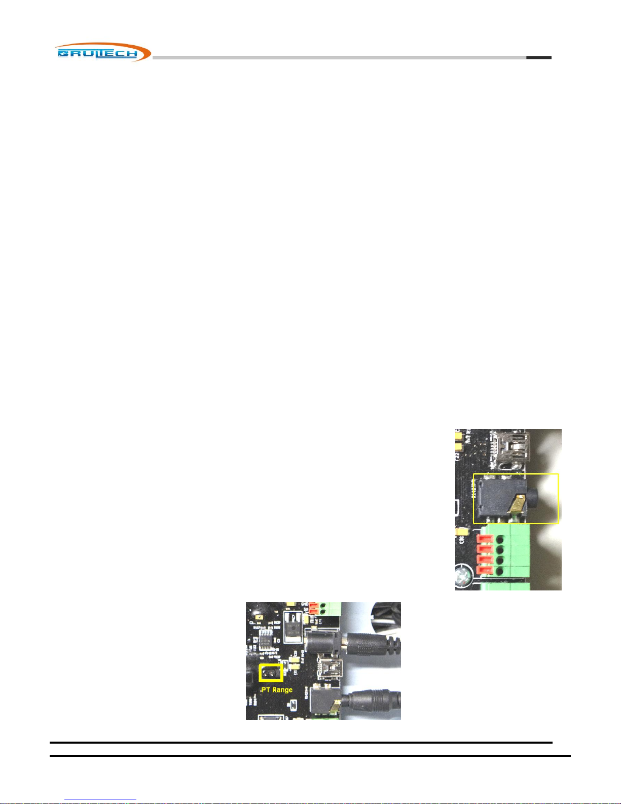
The 3.5mm PT input is the most commonly used. By using its “stereo” capability, this jack may
accept two voltage ranges: 14VAC and 333mVAC.
Typically, the PT signal to the GEM will be from a 120V/12VAC UL/c certified wall transformer. It
will connect to the GEM using a 3.5mm “mono” plug.
Potential transformers will also be available with primary (line) voltage from 120VAC to 480VAC
with an output signal in the 333mV to 666mV range. These PTs are fitted with a stereo plug
making connection via ring and sleeve only (tip not connected). This allows the GEM to use the
lower PT range.
There is a two pin jumper located near the 3.5mm jack to change the 333mV range to 666mV.
This jumper should be pre-installed based on the PT being used.
October 7, 2012
www.brultech.com Copyright © 2012 Brultech Research Inc. All rights reserved.
Page 24
Brultech Research Inc
24
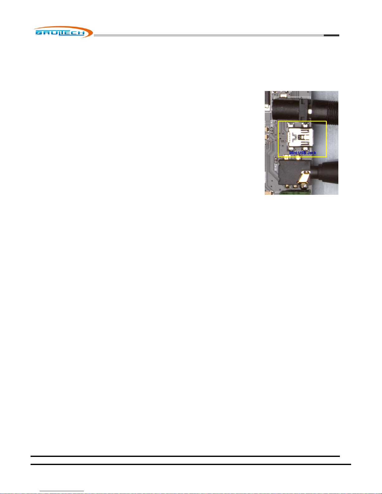
Mini USB Jack
The mini USB jack is NOT a USB communication port!
The USB jack is for future option of a combined PT/Power Supply. The jack is configured
such that the GEM may be powered using +5VDC USB power connection. The standard
USB D+ and D- connections are used to supply 333mVAC potential transformer signal.
October 7, 2012
www.brultech.com Copyright © 2012 Brultech Research Inc. All rights reserved.
Page 25
Brultech Research Inc
25
Power Supply Input
Power to the GEM is supplied via a 2.1mm X 5.5mm barrel plug from a +5VDC power supply (center is +). Alternately, power
may be supplied by the mini USB jack instead of the barrel jack (not both at the same time). These two supplies are
connected together on the PCB. It is recommended to use the supplied transformer. Id a substitute is to be used, it MUST be
UL/CSA (USA/Canada) certified (or whatever certification applies to your Country).
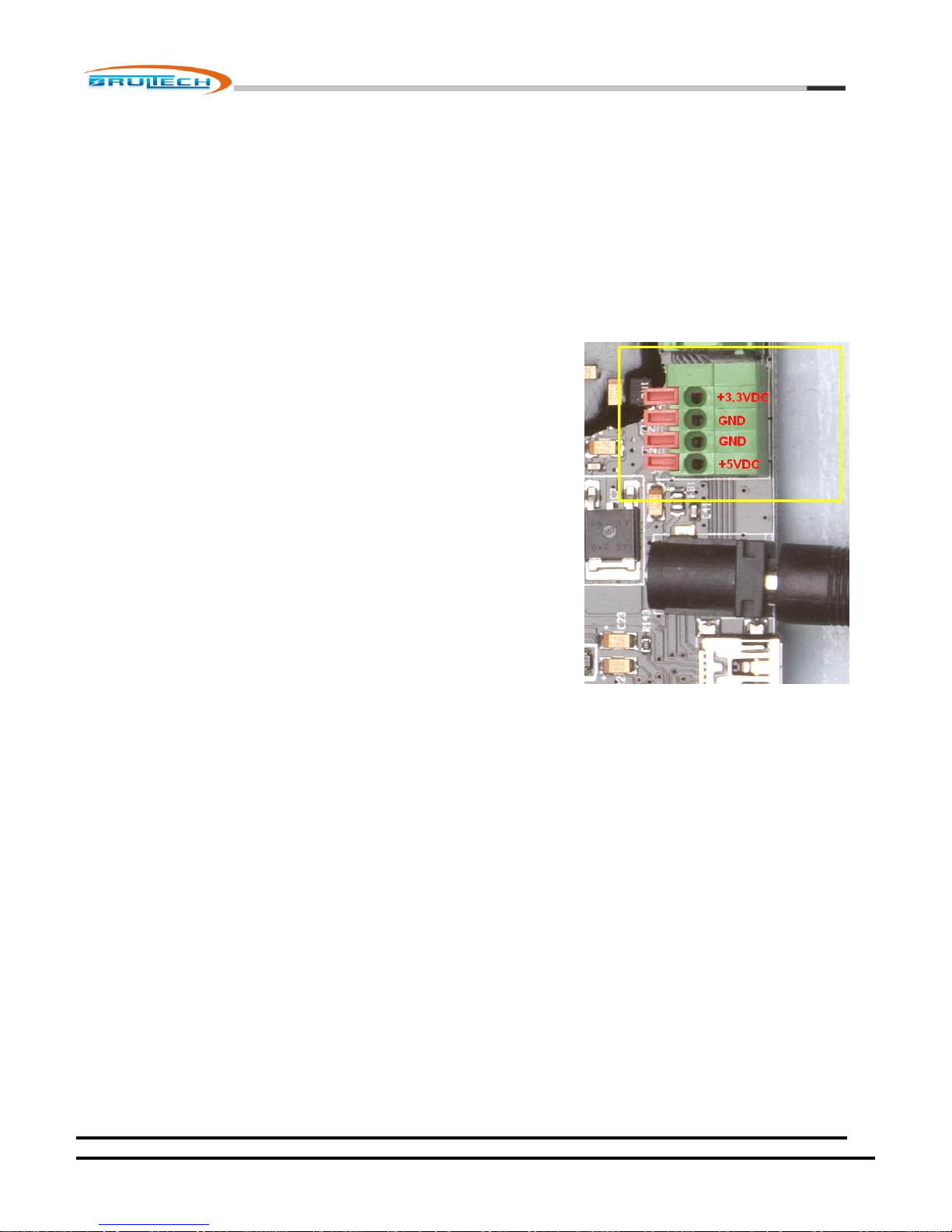
Power Supply Access Terminal Block
A terminal block provides access to the GEM’s +5VDC and +3.3VDC power
supplies. It is recommended not to use these terminals unless examples are
provided in this document.
The purpose of these terminals is to provide power for future options.
October 7, 2012
www.brultech.com Copyright © 2012 Brultech Research Inc. All rights reserved.
Page 26
Brultech Research Inc
26
CT Installation
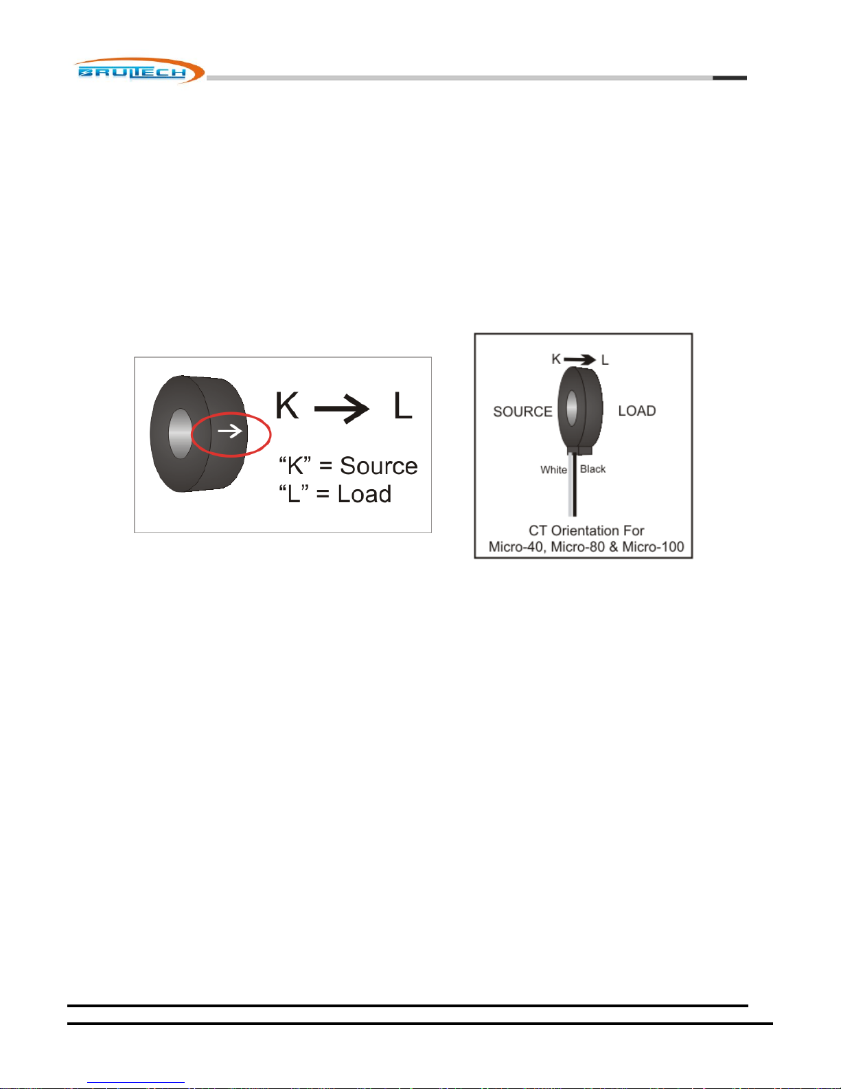
All of the Brultech CTs have a marking “K L” except for the Micro CTs. This mark is used to specify the orientation of the CT
when installed. “K” signifies the “source” which is where the power is coming from and “L” is the “load” which is the device
receiving power.
When the CTs are installed, the arrow should point to the load. There is no harm if the CTs are installed backwards since this
can be corrected by reversing the black/white leads when connecting to the GEM. Paying attention to orientation will simplify
the connection process especially for 240V loads using two CTs and when connecting to 3-phase systems.
October 7, 2012
www.brultech.com Copyright © 2012 Brultech Research Inc. All rights reserved.
Page 27
Brultech Research Inc
27
Single/Split Phase Residential System
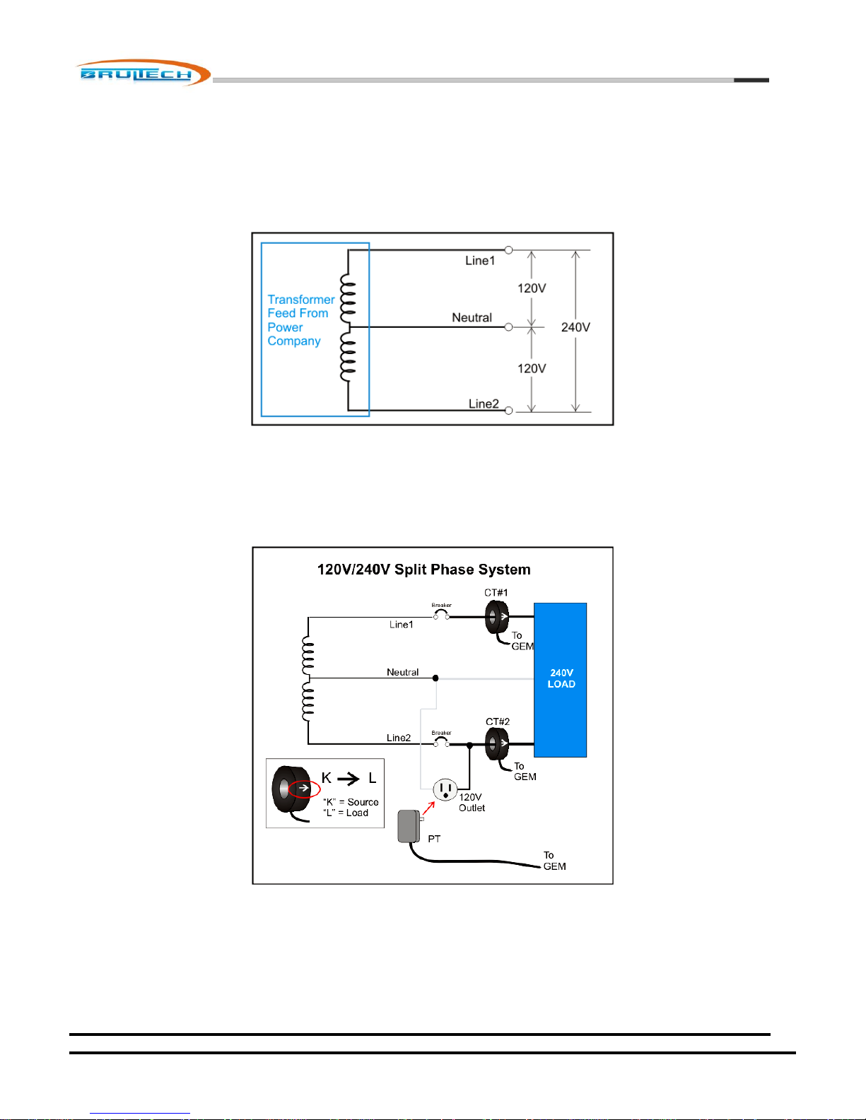
Almost every home in North America has its power supplied by a 120V/240V split phase service.
When installing CTs on a single or split phase system, it is recommended to install them such that the arrow points toward
the load as illustrated in the diagram below. Following this rule will simplify the task of polarizing the CTs if more than one CT
is connected to a given channel such as would be the case for 240V loads.
Some 240V loads may be monitored with a single CT as long as it does not required a neutral conductor which is common for
many water heaters, baseboard heaters and some water pumps.
October 7, 2012
www.brultech.com Copyright © 2012 Brultech Research Inc. All rights reserved.
Page 28
Brultech Research Inc
28
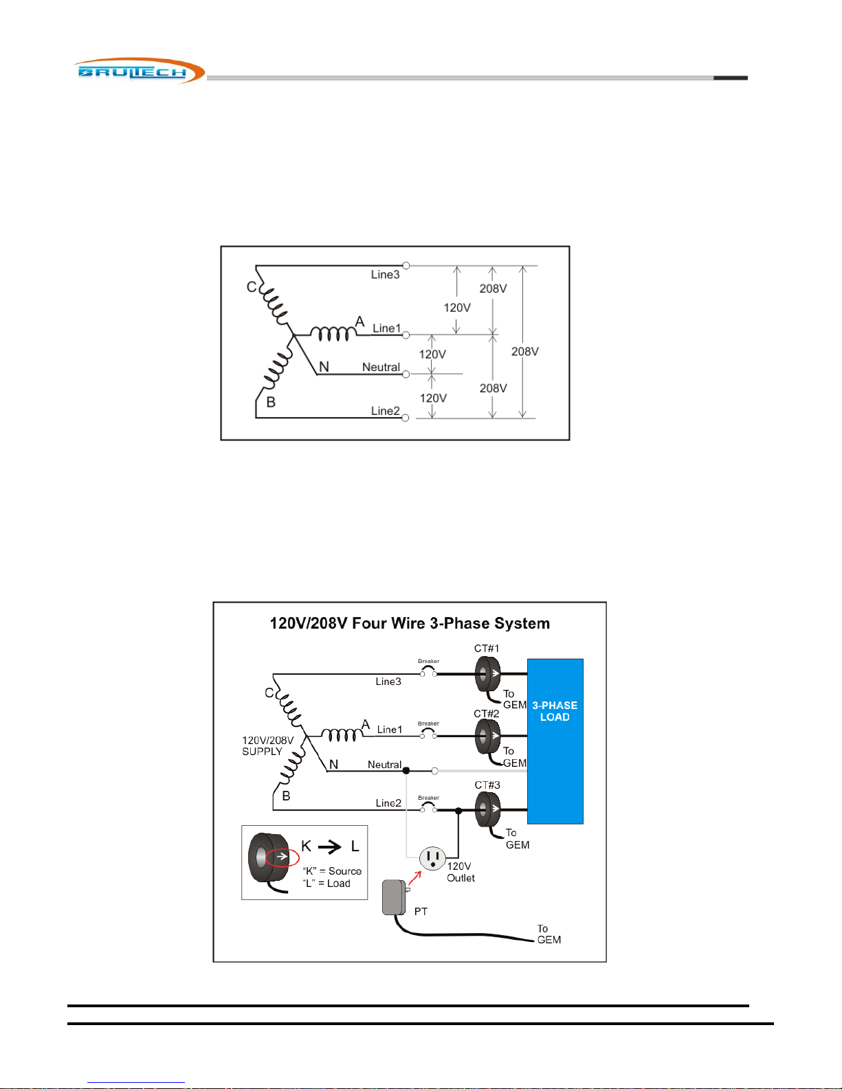
Most commercial and light industrial buildings will have three phase panels. Three phase (sometimes referred to as
“polyphase”) is preferred for powering large motors such as those found in rooftop AC units, refrigeration units and
machinery. The most common system is the 4-wire “Y” 120V/208V feed as shown in the diagram below.
Three Phase (Polyphase) 4-Wire Wye(Y) System
The GEM uses a unique method of monitoring the voltage of a three phase system. Typically, energy monitors require all
three voltages to be monitored. The GEM simplifies matters by monitoring a single voltage phase. The diagram above shows
how the simplicity of the installation since the voltage is obtained via a wall-transformer. Other PT solutions are also available
that allow monitoring 3-phase systems up to 480V.
When setting up the GEM’s input channels, one of the parameters required for 3-phase systems is the phase for a given
channel: A, B or C. The following paragraph describes how to determine the proper setting.
In the diagram above, CT#3 will be configured for Phase A because the PT is connected between Neutral and Line2.
October 7, 2012
www.brultech.com Copyright © 2012 Brultech Research Inc. All rights reserved.
Page 29
Brultech Research Inc
29
120V Outlet (for PT)
connected to Line1
120V Outlet (for PT)
connected to Line2
120V Outlet (for PT)
connected to Line3
Line1 CT = Phase A
Line1 CT = Phase C
Line1 CT = Phase B
Line2 CT = Phase B
Line2 CT = Phase A
Line2 CT = Phase C
Line3 CT = Phase C
Line3 CT = Phase B
Line3 CT = Phase A
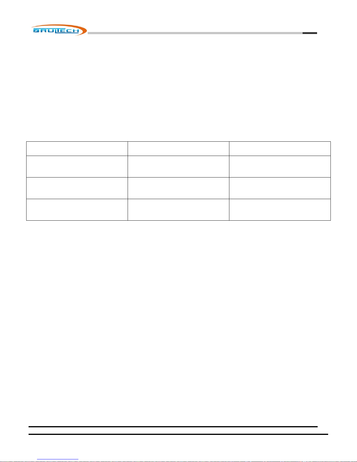
The important step is to note which phase (or Line) connects to the outlet which powers the “PT”. This is the reference and
will always be considered “Phase A” when configuring the GEM. For example in the diagram above, the “120V Outlet” is
connected to “Line2”, therefore the circuit that “CT#3” (which is connected to the Line2 load) is sensing will be configured for
“Phase A. In this example, since Line2 = Phase A then:
Line3 = Phase B
Line1 = Phase C
Based on this example, the channel that CT#1 is connected to will be configured for “Phase B” and CT#2 channel will be
configured for “Phase C”.
To summarize, here are the possible combinations:
October 7, 2012
www.brultech.com Copyright © 2012 Brultech Research Inc. All rights reserved.
Page 30
Brultech Research Inc
30
Type A CT
Type B CT
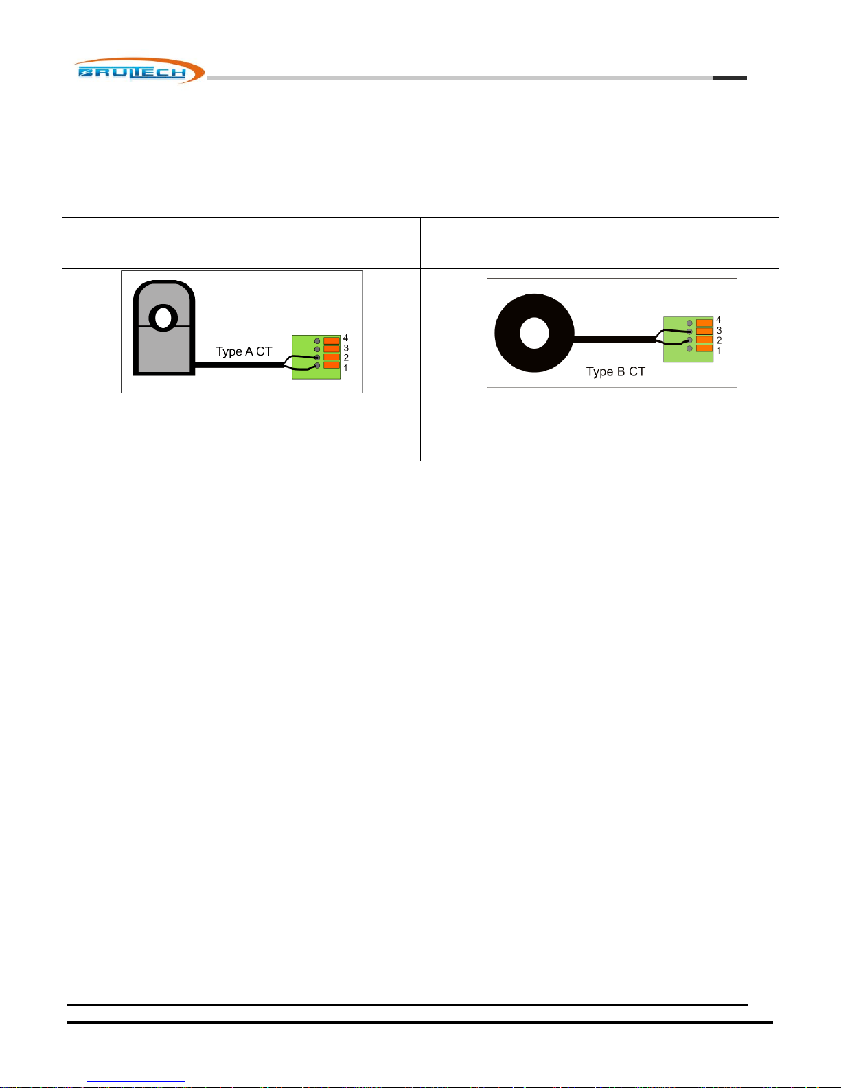
Terminal 1: White Lead (Or black with white stripe)
Terminal 2: Black Lead
Terminal 2: White Lead (Or black with white stripe)
Terminal 3: Black Lead
CT Connection (Four-Wire WYE System)
Depending on the CT type used, the color code for the connecting leads should be as indicated in the table below. When
setting up to monitor a three phase WYE system or load, only one CT is allowed per channel. The technique used to couple
two CTs on a single channel only applies for single/split phase systems and NOT for three phase systems.
Displayed Polarity
Once the CTs have been connected and it is time to setup the connected channels, the “Phase A” channel should be setup
first. This is the CT channel which connects to the same phase as that which the PT is connected to.
Connect to the GreenEye Monitor using the setup program and make sure you have a connection established. (See “Setup
Software” manual for more information).
Select “System” from the setup program and make sure the “Polyphase” option is enabled. Click “Save Settings”.
Select “Channels” from the setup program, then refresh the values by clicking the “Update Summary” button. All CT settings
and corresponding phase settings will be displayed. Set the CT values (type and range) then set the phase values as
determined by the table (above).
Let’s first concentrate on the “Phase A” channel. Select the “Real-Time Data” tab of the setup program. Make sure that the
load is consuming power and that a wattage value is displayed for phase A. If the displayed watt value for phase A is a
negative value, then you can easily rectify this by unplugging the PT, giving it half a turn and re-plugging it such that the two
prongs are reversed. This will cause the negative value to because positive.
Verify that phase B and C channels have positive values such as phase A now does. If this is not the case, try changing the
phase B channel configuration to C and likewise phase C to B. This should provide positive values for all three phases.
Given a three phase load, the total power for that load will be the sum of all three channels used to monitor it.
In some cases, you may encounter a load such as a water heater using only two of the three phases. The procedure is the
same. Remember that there is a possibility that the heater uses only phases B and C. Again the same principle applies, simply
disregard the unused phase and the total power is the sum of the two phases used.
October 7, 2012
www.brultech.com Copyright © 2012 Brultech Research Inc. All rights reserved.
Page 31

Brultech Research Inc
31
Three Phase (Polyphase) 3-Wire Delta (∆) System
October 7, 2012
www.brultech.com Copyright © 2012 Brultech Research Inc. All rights reserved.
Page 32
Brultech Research Inc
32
Communication Link
The GEM provides a multitude of hardware communication options such as RS-232 which is standard on all GEM models.
Optionally, WiFi, Zigbee® (XBee® module), Ethernet or other options are available. The “other” options is based on a header
provided with “UART” access for those requiring a custom solution such as RS-485, Z-Wave® or other such solution.
Along with all of the hardware options, the GEM offers various packet formats and APIs for communicating with data hosts.
COM Ports
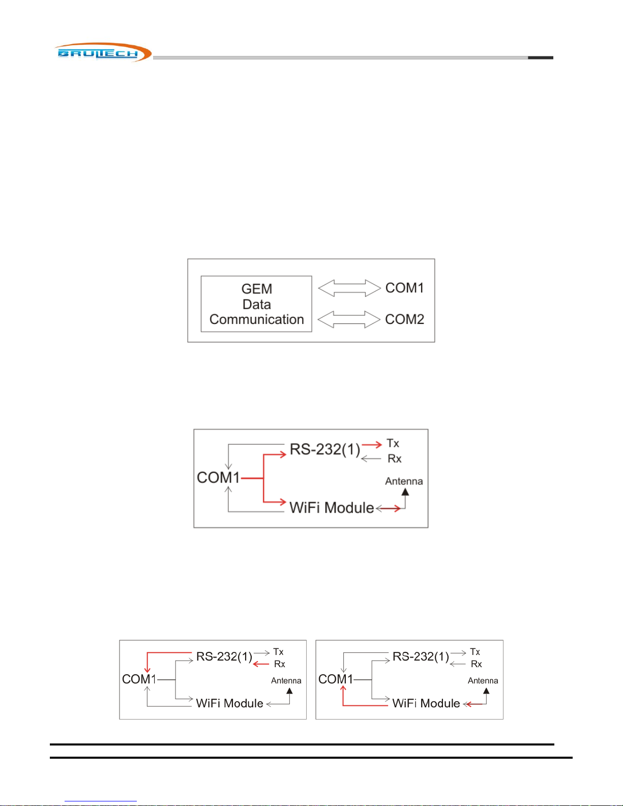
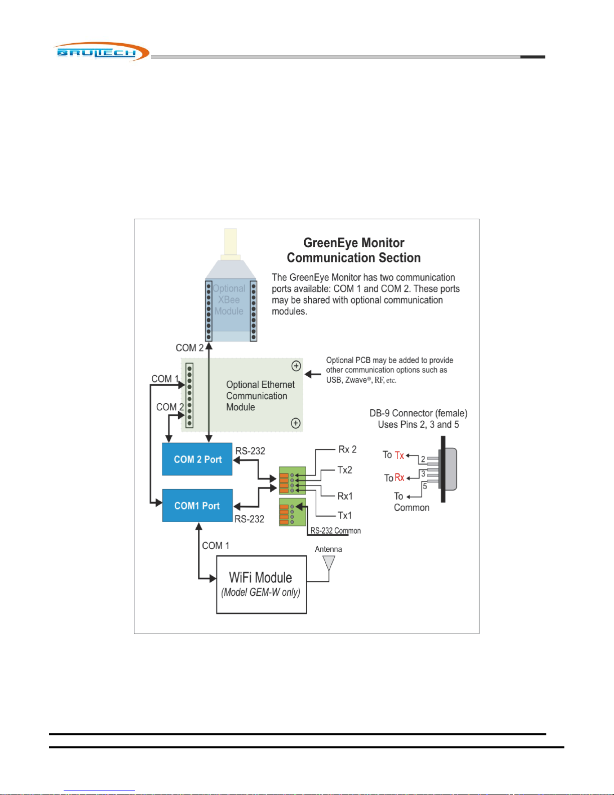
The GEM uses two communication ports: COM1 and COM2. In general, data from both ports are identical.
Each COM port is accessible via one of two RS-232 ports: RS-232(1) and RS-232(2). Any of the optional communication
options described previously will share a com ports with its corresponding RS-232 port. For example, the RS-232(1)
connection will receive the same data as that being sent to the WiFi module. This means that when the GEM sends a data
packet or response to a command, the data will be transmitted via WiFi and RS-232(1) serial port. See diagram below.
Figure x
If command data is sent to the GEM via the RS-232(1) serial port, the WiFi module will not “hear” this command. The same
applies if data is sent to the GEM via WiFi. See diagrams below.
October 7, 2012
www.brultech.com Copyright © 2012 Brultech Research Inc. All rights reserved.
Page 33
Brultech Research Inc
33
Figure x
The same concept applies to other shared COM ports.
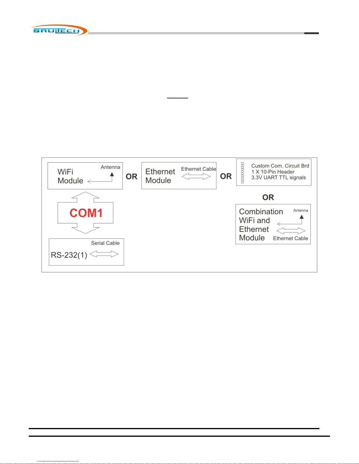
Here is a summary of how the COM ports may be shared:
COM1 is connected to RS-232(1) and may be shared with only one of the following optional devices:
WiFi Module
Ethernet Module
Combination WiFi/Ethernet Module
Custom PCB connected to the 1 X 10 pin header (3.3V TTL level signal). *NOTE: Improper connection to the header
may damage the GEM and void warrantee. Consult Brultech before experimenting with this port.
October 7, 2012
www.brultech.com Copyright © 2012 Brultech Research Inc. All rights reserved.
Page 34
Brultech Research Inc
34
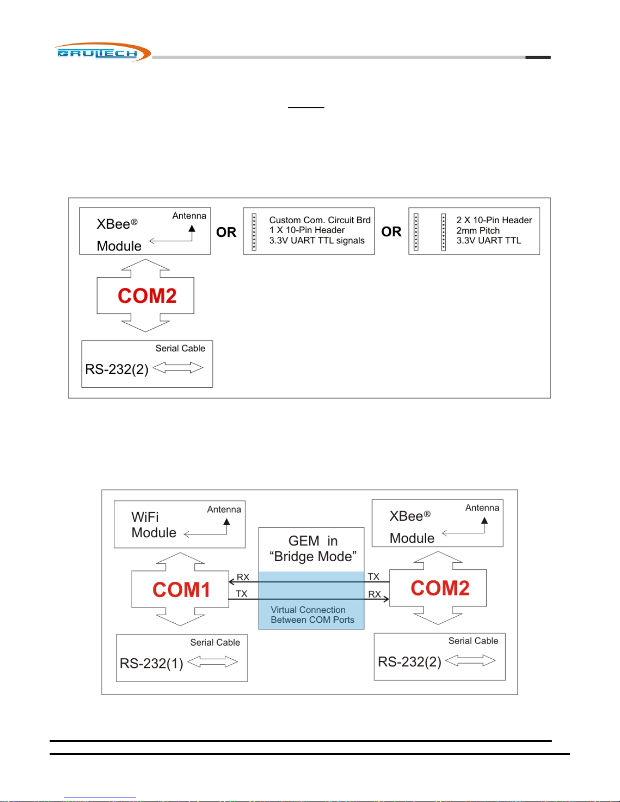
COM2 is connected to RS-232(2) and may be shared with only one of the following optional devices:
XBee® Module
Device compatible with the XBee® module footprint and pin-out
Custom PCB connected to the 1 X 10 pin header (3.3V TTL level signal).* Improper use may damage the GEM and
void warrantee. Consult Brultech before experimenting with this port.
COM Port Bridge Mode
For setup purposes, there is a method whereby a serial port or communication device can talk directly to one another as long
as each is on a different COM port. This is done using “Bridge Mode”. This mode creates a virtual connection between a
COM1 and COM2 device.
The purpose for this is to enable setup or firmware upgrades for specific communication devices. For instance, an XBee®
module’s firmware may be upgraded by connecting to RS-232(1) and bridged to communicate directly with the XBee®
October 7, 2012
www.brultech.com Copyright © 2012 Brultech Research Inc. All rights reserved.
Page 35
Brultech Research Inc
35
module. Another common use would be to connect to the RS-232(2) port and setup parameters for the WiFi module (if
present).
Bridge mode is baud independent which means that the virtual wire section will work at any common baud rate without any
required configuration. The baud rate setting for each device must however be the same. For example, if you are bridging an
XBee® module to setup the WiFi module, both devices must be set to the same baud rate. Bridge mode does not support
hardware flow control.
When the GEM is in bridge mode, it no ceases all operations and only operates as a bridge. Bridge mode is exited by a special
timed command sequence or simply by momentarily pressing the GEM’s push button switch (14).
October 7, 2012
www.brultech.com Copyright © 2012 Brultech Research Inc. All rights reserved.
Page 36
36
Every GEM device comes with two RS-232 ports. The RS-232 port may be used to
connect directly to an automation system, a “Serial to Ethernet” device such as
“EtherPort” or to a serial to USB adaptor. Either of these ports may be used at
the main communication gateway or simply to configure the GEM, the GEM’s
(optional) WiFi module or the GEM’s (optional) XBee® module.
The GEM is capable of being put in “Bridge Mode” which causes Com1 and Com2
to be linked together so that the RS-232 port can talk directly to a module on the
opposite port.
Connection to the RS-232 port is accomplished via terminal blocks #8 in the
“layout” section.
Typically only one RS-232 port would be used therefore there is only one
common (GND) connection available.
RS-232 Port
Brultech Research Inc
WiFi Communication Option
NOTE: This option will soon be discontinued due to erratic performance of Roving Networks’ RN-171 WiFly Module
The model GEM-W is equipped with a WiFi module. The module is initially configured so that a PC with WiFi can connect to it
in ADHOC mode for the purpose of setting it up to access a local wireless router. Once this setup is completed, the GEM then
connects to the WiFi router as a client.
Before the WiFi module is configured, you must determine the destination for the GEM data. This destination is where the
data will be hosted such as:
A energy monitoring hosting site (check-it.ca, smartenergygroups.com, etc)
Brultech local web-server/dashboard
Your own personal website
A local computer
The WiFi module communicates via COM1 port, therefore if RS-232 communication is required, COM2 RS-232 should be
used.
October 7, 2012
www.brultech.com Copyright © 2012 Brultech Research Inc. All rights reserved.
Page 37

Brultech Research Inc
37
Ethernet Module Option
The Ethernet module provides a robust connection to a network or PC. It is typically setup as a client although it may be
configured as a server. The mode selected mostly depends on the data hosting method selected. Currently our options
consist only of client mode applications although some customers have created custom software requiring the GEM to be
setup as a server.
The Ethernet module may be configured using the EtherX Configuration software available on our website.
Combination WiFi and Ethernet Communication Option
This preferred option provides a robust WiFi and Ethernet connection. Configuration is done via web browser connected to
the internal website. Both options may be used simultaneously. Both options use COM1 leaving COM2 open for RS-232 or
XBee® module.
XBee® Module Option
The XBee® module provides a wireless link using ZigBee® communication via “mesh” network. The GEM incorporates a
module socket for easy installation of the two most popular module types: whip antenna or RPSMA antenna connector.
The baud rate must be changed from XBee’s default 9600 baud to 19,200 baud.
Since the ZigBee protocol has a limited data throughput and the GEM packets are fairly large, the GEM may be configured to
send ZigBee data in specified chunk sizes along with a specified time between chunks.
Hardware flow control may also be enabled to further protect the module from buffer overrun.
Custom Com PCB Header
There is a footprint on the GEM to accept a custom designed communication circuit board. This is available only if the GEM
does not have a WiFi or Ethernet module installed.
The purpose for this footprint is to allow the development of a custom communication circuit board which would allow an
alternate communication method such as RS-485, RS-422, Z-Wave, etc. Additionally, the PCB developer may wish to include a
processor on board to incorporate proprietary API, functions, security, etc. The header consists of a 10-pin female socket with
a 2mm pitch.
1. Ground/Common
2. Vcc +3.3V
3. COM1 Reset (output) Low Active
4. COM1 CTS Flow Control (input)
5. COM1 Tx (output)
6. COM1 Rx (input)
7. COM2 Tx (output)
8. Green LED (hi active)
9. Yellow LED (hi active)
10. COM2 Rx (input)
NOTE: Please contact us for more information before using this header. Improper use may damage the GEM.
October 7, 2012
www.brultech.com Copyright © 2012 Brultech Research Inc. All rights reserved.
Page 38

Brultech Research Inc
38
Firmware Upgrades
It is very important establish a robust communication link with the GEM before performing firmware upgrades.
The GEM has two processors, “COM” and ENG”. Each processor has its own specific firmware with “GEM_C” or “GEM_E” as
part of the filename followed by the version number. Example:
COM firmware file: “GEM_C Firmware 1.59.fmw“
ENG firmware file: “GEM_E Firmware 1.36.fmw“
It is not always required to upgrade both processors. Typically the COM processor may require upgrades as more features are
made available. The ENG firmware may not need to be upgraded.
Firmware upgrade is accomplished using a PC in conjunction with the GEM Setup Application. This program is a Java “.jar”
application which runs on Windows®, Linux® or Apple®.
The PC connects to the GEM using any of the available communication links:
Ethernet
WiFi
XBee®
RS-232
USB , via serial to USB cable
If a USB or Serial connection is used instead of a TCP/IP connection, a bridge application will need to be used to bridge the
Serial connection to a TCP/IP connection compatible with the GEM setup program.
As mentioned earlier it is important to have a good wireless connection when upgrading the firmware. If th e wireless signal
is week or intermittent then it is recommended to move the wireless devices in closer proximity.
COM Processor Firmware Upgrade
The COM processor is the GEM’s main processor. It is also responsible for coordinating data flow when upgrading the ENG
processor. There could be a situation whereby the COM processor’s firmware becomes corrupt during an upgrade due to
interruption in communication. If this occurs, the GEM will no longer be functional. Fortunately there is a procedure to
recover from this situation as explained later in this chapter.
The most recent firmware file may be downloaded from our website. Notes indicating issues resolved or features added for
each firmware version are also available and should be viewed before upgrading. This will discourage needless upgrades if
the changes do not affect your application.
A communication connection between the GEM and a PC running the “GreenEye Monitor Setup” program will have to be
established. If the GEM is configured to send data to an online hosting site the communication module may need to be redirected to the PC unless a secondary communication method is available. For example, if data is forwarded to an online host
via WiFi or Ethernet connection (GEM COM1), firmware upgrade may be performed using any of the COM2 options such as
RS-232 or XBee® module. If no other COM2 option is readily available, the TCP/IP connection will need to be redirected from
the online data host’s IP address to that of the PC. The procedure for doing this will depend on the type of communication
module used.
October 7, 2012
www.brultech.com Copyright © 2012 Brultech Research Inc. All rights reserved.
Page 39
Brultech Research Inc
39
Once a communication link is established between the GEM and the PC running the GEM setup program, the procedure for
upgrading the firmware is:
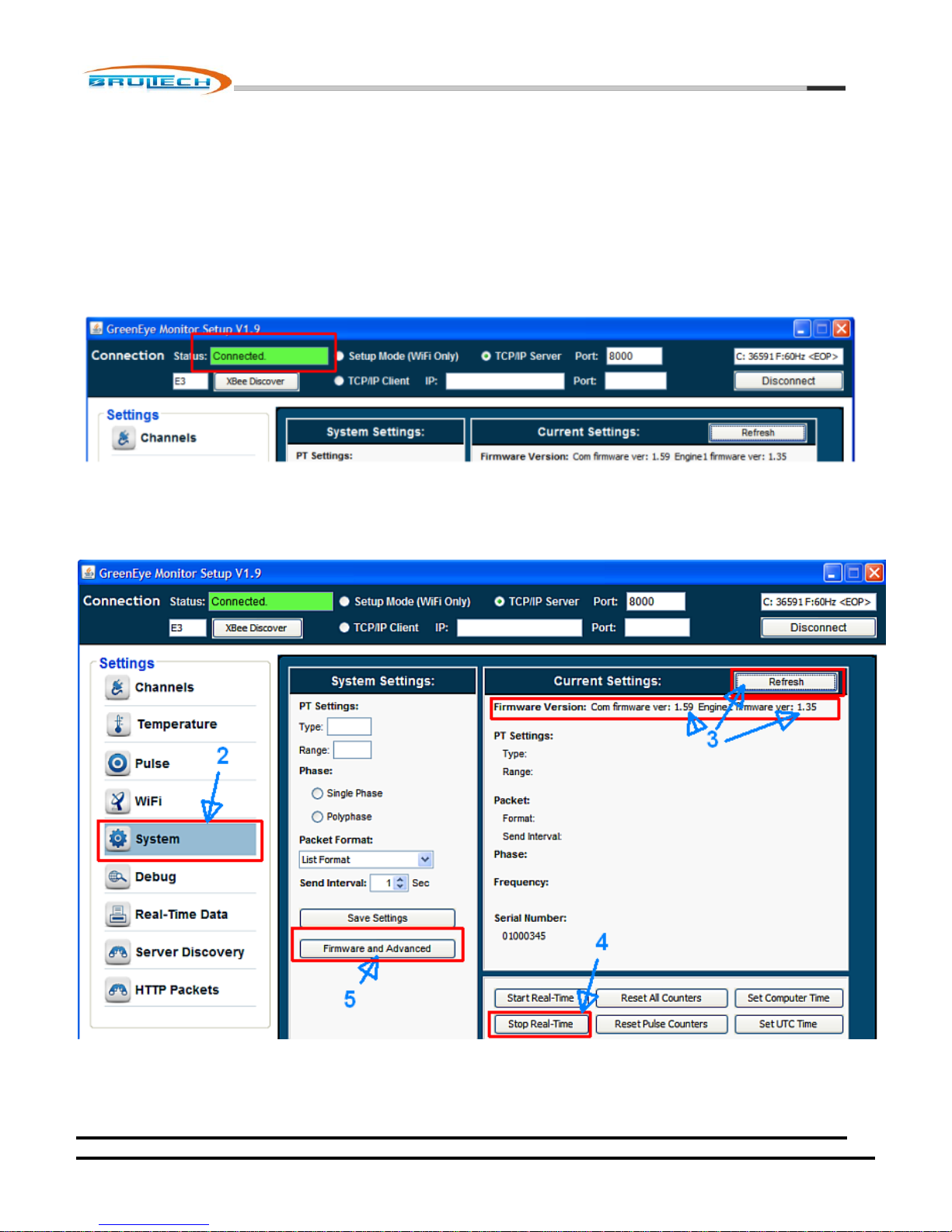
1. Verify that the communication link is established by verifying that the GEM setup program’s “Connection Status”
indicates “Connected” inside the green box on the top left window of the program.
2. Click “System” from the left menu.
3. Click “Refresh” and take note of the current firmware version
4. Click “Stop Real-Time”.
5. Click “Firmware and Advanced”. This will open a new window.
October 7, 2012
www.brultech.com Copyright © 2012 Brultech Research Inc. All rights reserved.
Page 40
40
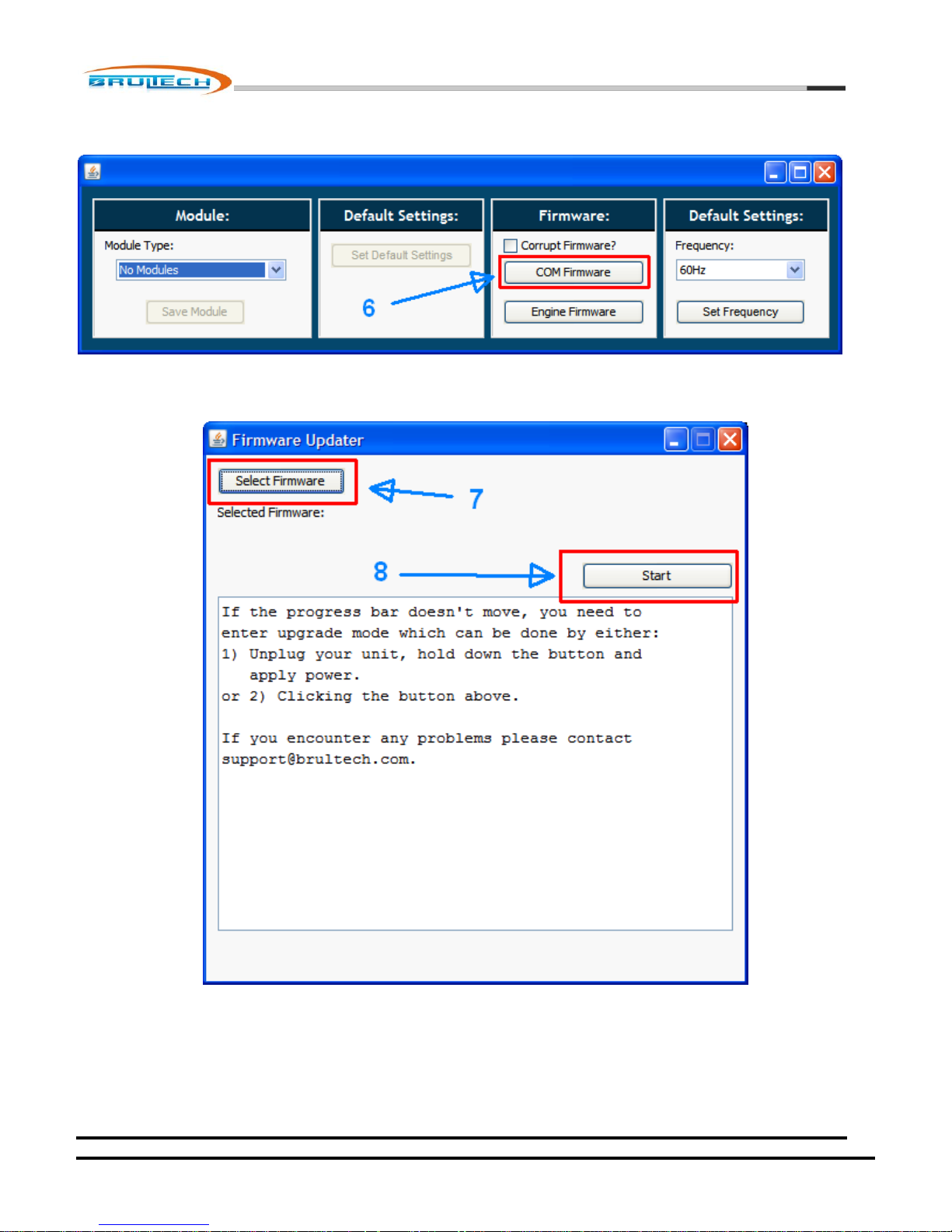
6. Click “COM Firmware”. A window will open
7. Click “Select Firmware”. Select the firmware file.
Brultech Research Inc
8. Click “Start”
Depending on the communication link, it may take a couple of minutes for the upgrade to complete. Pay attention to the
trail of dots generated as data is transferred.
October 7, 2012
www.brultech.com Copyright © 2012 Brultech Research Inc. All rights reserved.
Page 41

Brultech Research Inc
41
If for any reason the GEM stops responding midway through the upgrade wait several seconds since there may be a pause in
data transfer when using WiFi or XBee®. If there is no response for 1 minute or so and the upgrade has not completed.
Something may have occurred to corrupt the firmware. If so, follow the procedure in “Recovering from corrupt COM
firmware” section below.
Recovering From Corrupt COM Firmware
Firmware may become corrupt if data communication is interrupted while upgrading firmware. In the event that this
happens, the GEM will not function properly if at all. There is a special procedure used to recover from such scenario:
1. Remove power (5VDC) from the GEM.
2. Remove the CR-2032 battery
3. While holding down the PB switch, power up the GEM
4. Once the GEM is powered, release thee PB switch. The system LED (left) will glow a solid red
5. Establish a robust communication link between the PC and the GEM
6. Make sure the “Corrupt Firmware” checkbox of the GEM setup program is checked
ENG Processor Firmware Upgrade
The procedure for upgrading the ENG firmware is the same as that for the COM firmare (described above) with the following
differences:
1. Once a communication link is established, send a “Reboot COM” command. This is done by clicking the “Debug”
menu and clicking “Reboot COM” command.
2. In step 6, click “Engine Firmware” button instead of the “COM Firmware” button.
If the ENG firmware upgrade fails for any reason and the ENG firmware becomes corrupt, the method for recovery is
different than that of the COM firmware.
October 7, 2012
www.brultech.com Copyright © 2012 Brultech Research Inc. All rights reserved.
Page 42

Brultech Research Inc
42
Recovering From Corrupt ENG Firmware
Recovery from a failed ENG firmware upgrade is different and simpler than that for the COM corrupt firmware. Simply press
the PB momentarily so that the SYS LED returns to green then repeat the procedure.
DO NOT CHECK THE “Corrupt Firmware” OPTION IN THE SETUP PROGRAM! This option only applies to the COM firmware.
If the GEM is at a remote location and the PB cannot be pressed, simply wait for 80 seconds as the GEM will automatically
exit the ENG firmware upgrade function. Again, the ENG firmware upgrade can be attempted again.
October 7, 2012
www.brultech.com Copyright © 2012 Brultech Research Inc. All rights reserved.
Page 43

43
Power Metering
Number of Channels
32 (expansion available in the future)
Measurement
POWER:
True (or Real) Power using high speed volt and current sampling
VOLTAGE:
True RMS
Accuracy
Power/Energy Measurements:
Typically +/- 1% plus CT accuracy
Voltage Measurement:
Better than 1% with PT-Type value trimmed to a reference.
Sampling Frequency
Voltage sampled @ 20.8 kHz
Current sampled @ 10.4 kHz
Maximum Input Current
Dependent on current transformer. Currents greater than 1,000A may be monitored.
Current Transformer
Input
Type A CT with AC mV output:
700 mV max for single CT
350 mV max for each of two connected CT on a given channel
Type B CT with AC mA output:
103 mA max for single CT
51.5 mA max for each of two connected CT on a given channel
NOTE:
Exceeding the specified input values will affect channel accuracy.
Connecting a Type B CT to terminals designated for TYPE A CTs may cause a
channel overload to the point that all channels display unpredictable power
values
Input Impedance:
1,000 ohms for Type A CT connection. Terminals 1&2 and 3&4
6.8 ohm (burden resistor) for Type B CT connection. Terminals 2&3
Potential Transformer
Input
3.5mm Jack PT Input:
Mono plug PT signal 8VAC to 18VAC. Voltages greater than 14VAC require a
PT shorting jumper to attenuate PT signal.
Stereo plug: “sleeve” and “ring” connection, “tip” not connected. 333 mVAC
without PT shorting jumper or 666mVAC with shorting jumper.
Mini USB Jack Input:
PT signal to pins 3 and 4 of mini USB
333 mVAC without PT shorting jumper or 666mVAC with shorting jumper
Brultech Research Inc
Technical Specification
October 7, 2012
www.brultech.com Copyright © 2012 Brultech Research Inc. All rights reserved.
Page 44

Brultech Research Inc
44
Potential Transformer
(PT)
GEM supplied with UL/c wall transformer with < 2 degree phase error.
Optional PT (part number PT01) may be ordered:
1% accuracy
Input voltages between 120V to 480V.
600V rated leads
Load/System Types
Single and Polyphase systems.
System Frequency
50Hz or 60Hz. Default is 60Hz. May be configured for 50Hz via setup software.
Resolution
Power: 1 Watt
Energy: 1 Watt-Second (.000000277 kilowatt-hour)
Voltage: 0.1 Volt
NET Metering
All channels are capable of NET metering. Two sets of watt-second counters are used
for energy flow direction.
Watt-Second Counters
Each channel has two 5-byte incrementing watt-second counters, one absolute and
one polarized.
Counter “wrap around” occurs after 240 watt-seconds or 305,419 kilowatt-hours.
Pulse Counting Channels
Four Individual pulse counters
Two dry contact inputs
Two DC pulse inputs
Counter Input
Counter #1 and #2:
Requires DC pulses
Galvanic isolated from GEM system via opto-isolator
Requires DC pulses between 3.5 and 24VDC. (5VDC ideal)
Counter #3 and #4:
Requires “dry” contact closure from reed switch, relay, etc.
Input is not isolated from the GEM power supply therefore connection to
this input must be isolated from the pulse source’s power supply. This is
typical when using reed switches.
Pulse Frequency
Less than 1pps (pulse/second)
*Subject to change
Pulse Width (Duration)
Minimum pulse duration 550ms.
*Subject to change
Counter Registers
Each counter has a 3-byte up-counter
Counter wraps around when full 2
24
pulses.
Counter Volatility
Counter values are stored in RAM and preserved by battery power when a power
interruption occurs.
Pulse Counting
October 7, 2012
www.brultech.com Copyright © 2012 Brultech Research Inc. All rights reserved.
Page 45

45
Temperature Sensor
Channels
8 Channels
Sensor Type
Uses 1-Wire Bus system
Compatible with the following 1-Wire sensor types:
DS18B80
DS18S80
1-Wire Bus
Uses three push terminals:
GND
DATA
+5 VDC
“1-Wire” devices are connected in parallel
For more info visit: http://www.1wire.org/
Conversion Interval
All temperature sensors perform a temperature conversion every 16 seconds
Sensor Read Interval
Each enabled temperature sensor is read once every 64 seconds
One of eight temperature sensors is read every 8 seconds, hence 8 X 8 = 64 sec
Temperature Units
The GEM may be configured for Celsius or Fahrenheit degrees
Temperature Resolution
0.5o C resolution. Fahrenheit degree values are derived from the C value and
converted to 1 decimal point accuracy.
Standard
Communication
Ports
RS-232 via COM1 and RS-232 via COM2
19,200 baud 8-bits, no parity, one stop bit (8N1)
GND, TX, RX no hardware flow control
Connection via “push terminals”
Optional Board SMT
Soldered WiFi Module
Uses Roving Networks RN-171 WiFly Module
Receive Sensitivity: -83dB typical
Output Power: 12 dBm
Serial Communication 19,200 baud
On board wire whip antenna
Ethernet Module
Uses third party Ethernet Module
Supports: TCP, UDP, ICMP, IPv4 ARP, IGMP, PPPoE, Ethernet
Client, Server and Mixed modes. Default is “Client” mode
10BaseT/100BaseTX Ethernet PHY
Configured via UDP using simple setup application
Temperature Sensing
Brultech Research Inc
Communication
October 7, 2012
www.brultech.com Copyright © 2012 Brultech Research Inc. All rights reserved.
Page 46

Brultech Research Inc
46
WiFi+Ethernet Module
Provides Both Wifi and Ethernet Options simultaneously
Support 802.11b/g/n wireless standards
Output Power:
o 802.11b: +20dBm
o 802.11b: +18dBm
o 802.11b: +15dBm
Web Configuration Page
Supports WEP/WPA-PSK/WPA2-PSK/WAPI
Encryption: WEP64/WEP128/TKIP/AES
RP-SMA 2dBi external antenna
XBee® (ZigBee®) Module
Socketed for Digi International XBee® ZB modules
Accepts any of the three ZB-24 module antenna options
Communicates at 19,200 baud
Hardware flow control may be enabled
GEM setup option provides the option of chunking data to XBee® modules in
order to limit data flow restrictions inherent with ZigBee® protocol
Data Communication:
Real-Time Data:
May be configured to “push” energy usage data at a user defined interval or
“pull” data via API
Various data packet formats available
May be configured to post data using “POST” or “GET” methods
Efficient binary packet options available
Packet formats available for custom software development
Custom packet formats may be available based on the project size
Setup and Setting Commands
Documentation available listing the commands used to read or write GEM
setup parameters
GEM Firmware Upgrades
Firmware upgrades may be accomplished using any of the communication options
above including USB if a “serial to USB” adaptor is available.
Alternate
Communication
Options
Custom communication solutions are available via a 10-pin header or XBee® socket
header providing access to UART TTL COM1 or COM2 ports.
NOTE: Contact Brultech support before attempting to use these headers! Improper
use may damage the GEM and void warranty
Power Supply
Volt and Current:
5VDC +/- 5% UL/CSA approved
1.5A AC Adaptor (typically uses less than 200mA depending on
communication module used)
Consumption:
Typically less than 1 watt
Power Connection:
2.1mm X 5.5mm barrel jack, center positive (standard)
GEM System
October 7, 2012
www.brultech.com Copyright © 2012 Brultech Research Inc. All rights reserved.
Page 47

Brultech Research Inc
47
Optional power connection via mini USB jack instead of barrel jack
Isolation
The GEM must not be installed in the electrical breaker panel!
All connection to the GEM must have galvanic isolation to the power-line
Signals to the GEM must be Class2 low voltage
Current transformers (CT) and the Potential Transformer (PT) connected to
the monitored electrical panel must be UL/c listed and suitably rated above
the maximum voltage and current to be encountered
LED Indicators
Tri-color system LED (left side)
Displays system status, packet transfer, etc.
Two color communication device status (right side)
Displays status of the communication module. Color sequence depends on
the module installed
When no communication modules are installed only the green LED will come
on when 5VDC power is present. This is due to the jumper connection
between pins 2 and 7 of the header (#9)
Battery
CR-2032 battery used for memory backup when 5VDC power is lost
Typically drains less than 2 uA when GEM is powered down
Life: approximately same as battery shelf life
Battery replacement should be done while GEM is powered up if
accumulated watt-second, counter and time values are to be preserved
Memory Backup
Uses EEPROM to store GEM user settings
Battery backup holds CPU ram content during power outages. This includes
all watt-second, counter and time registers
Operating Temperature
Better than: 0 - 40C (TBD)
Humidity
5% to 95% non-condensing
Enclosure Material
UL94-V0 ABS Plastic
Dimensions
9 1/8” X 7 1/8” X 2”
Weight
(GEM Device Only)
Between 1.2 and 1.4 pounds depending on installed modules
FCC Certification
The GEM complies with Part 15 of the FCC Rules. Operation is subject to the following
two conditions: (1) this device may not cause harmful interference, and (2) this device
must accept any interference received, including interference that may cause
undesired operation.
Depending of the GEM options, the following wireless modules may be installed in
the GEM:
Roving Networks WiFly Module FCC ID: T9J-RN171
Digi International XBee® Module FCC ID: OUR-XBEE2
WiFi Module FCC ID: AZYHF-A111
October 7, 2012
www.brultech.com Copyright © 2012 Brultech Research Inc. All rights reserved.
Page 48
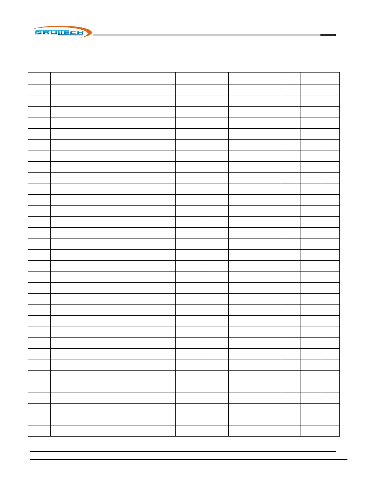
Brultech Research Inc
48
GEM
CH #
Load Description
Breaker
Number
Breaker
Amps
CT Model
120V 240V
1-CT
240V
2-CTs
1
A
2
A
3
A
4
A
5
A
6
A
7
A
8
A
9
A
10
A
11
A
12
A
13
A
14
A
15
A
16
A
17
A
18
A
19
A
20
A
21
A
22
A
23
A
24
A
25
A
26
A
27
A
28
A
29
A
30
A
31
A
32
A
Channel Assignment Worksheet
October 7, 2012
www.brultech.com Copyright © 2012 Brultech Research Inc. All rights reserved.
 Loading...