

Page 1
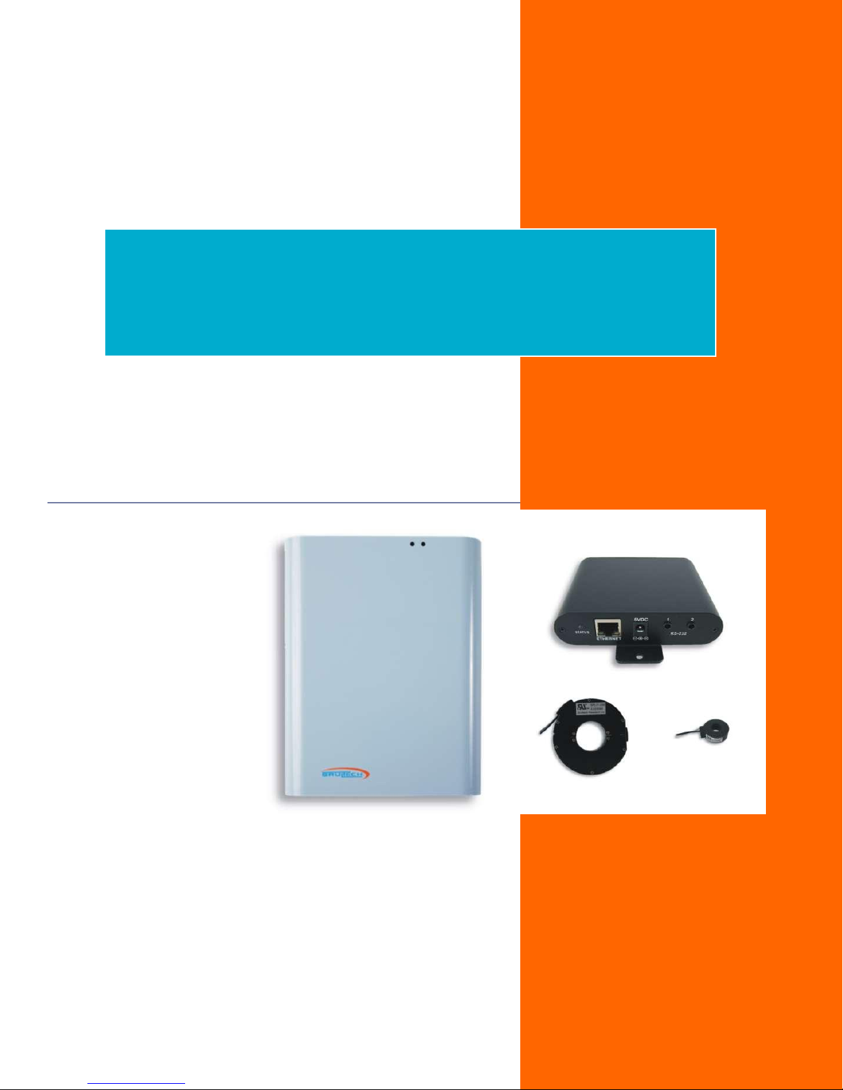
GreenEye/DashBox
System
Installation Manual
Document Code: SYS-MAN
Ver 2.2
2017-01-12
©Copyright Brultech Research Inc. 2017
Page 2

Introduction
TABLE OF CONTENTS
Introduction ..................................................................................................................................... 3
Important Notes ................................................................................................................................................................ 3
GEM Models ...................................................................................................................................................................... 3
Base model “GEM” ....................................................................................................................................................... 3
WiFi/Ethernet “GEM-WE” ............................................................................................................................................. 3
Ethernet Only “GEM-E” ................................................................................................................................................. 3
Important Safety Information .......................................................................................................... 4
Compliance ...................................................................................................................................... 5
FCC Compliance ................................................................................................................................................................. 5
What’s in the Package ...................................................................................................................... 5
GEM Mounting Location ................................................................................................................... 6
DashBox Location ............................................................................................................................. 7
Option 1: RS-232 cable (Recommended) ........................................................................................................................... 7
Option 2: TCP Connection .................................................................................................................................................. 8
Panel Layout .................................................................................................................................... 9
Fields .................................................................................................................................................................................. 9
CT Installation ................................................................................................................................ 10
CT Orientation .................................................................................................................................................................. 10
240V Loads ....................................................................................................................................................................... 10
Typical 240V Balanced Loads ..................................................................................................................................... 10
Typical 240V Unbalanced Loads ................................................................................................................................. 10
Route the CT Leads .......................................................................................................................................................... 10
CT Termination .............................................................................................................................. 11
GEM Terminal Strips ........................................................................................................................................................ 11
CT Termination ................................................................................................................................................................ 12
Single CT Connection ....................................................................................................................................................... 12
Connecting Two CTs on One Channel .............................................................................................................................. 13
Two Type “A” CT Connection ...................................................................................................................................... 13
Two Type “B” CT Connection ...................................................................................................................................... 14
SPLIT-30 CT Connection .............................................................................................................................................. 14
Power Supply and Wall Transformer .............................................................................................. 14
Communication .............................................................................................................................. 15
RS-232 Cable Installation ................................................................................................................................................. 15
Ethernet Cable Communication ....................................................................................................................................... 16
WiFi Communication ....................................................................................................................................................... 17
DashBox Setup ............................................................................................................................... 18
DashBox Power Up .......................................................................................................................................................... 18
DashBox WiFi Adapter Setup ........................................................................................................................................... 18
Locate DashBox on the Network ..................................................................................................................................... 19
Windows users ............................................................................................................................................................ 19
Mac or Linux users ...................................................................................................................................................... 19
Set a Static IP Address...................................................................................................................................................... 20
Ethernet Connected .................................................................................................................................................... 20
WiFi Connected ........................................................................................................................................................... 20
GEM Setup Page ............................................................................................................................. 21
Page 1
Page 3

Introduction
GEM Connected Via RS-232 (STS Cable) .......................................................................................................................... 21
GEM Connected Via Network (Ethernet or WiFi) ............................................................................................................ 21
WiFi/Ethernet GEM ..................................................................................................................................................... 21
Ethernet Only GEM ..................................................................................................................................................... 23
GEM Setup Procedure .................................................................................................................... 24
Configuring CTs ................................................................................................................................................................ 24
CT Settings .................................................................................................................................................................. 24
Multiply by Two .......................................................................................................................................................... 25
HTTP Post Setup ............................................................................................................................................................... 25
Packet Setup .................................................................................................................................................................... 26
For RS-232 Serial Communication .............................................................................................................................. 26
For WiFi or Ethernet Communication ......................................................................................................................... 26
Network Setup (GEM with WiFi/Ethernet) ...................................................................................................................... 27
For GEM with WiFi/Ethernet option ........................................................................................................................... 27
GEM with Ethernet only option .................................................................................................................................. 27
Net Metering ................................................................................................................................. 28
Setting Channel Polarity .................................................................................................................................................. 28
Toggling the Polarity ........................................................................................................................................................ 28
Effect of the PT on Polarity .............................................................................................................................................. 29
Temperature Sensors ..................................................................................................................... 30
1-Wire Bus ....................................................................................................................................................................... 30
Compatible Sensors ......................................................................................................................................................... 30
Pulse Count .................................................................................................................................... 31
Connection ....................................................................................................................................................................... 31
Appendix A .................................................................................................................................... 32
Important Security Info .................................................................................................................................................... 32
Appendix B .................................................................................................................................... 33
DashBox Switch Function ................................................................................................................................................. 33
Page 2
Page 4
GreenEye/DashBox System
INTRODUCTION
IMPORTANT NOTES
1. This manual is for installation on single phase or split single phase 120V/240V electrical systems only. The
CT installation described in this manual will not work for three phase service. This also applies to
120V/208V panels which uses two phases of a three phase source.
2. Safety is paramount! Read all safety notices and make sure you fully understand and follow the safety rules.
GEM MODELS
You should first determine which communication option (if any) is installed
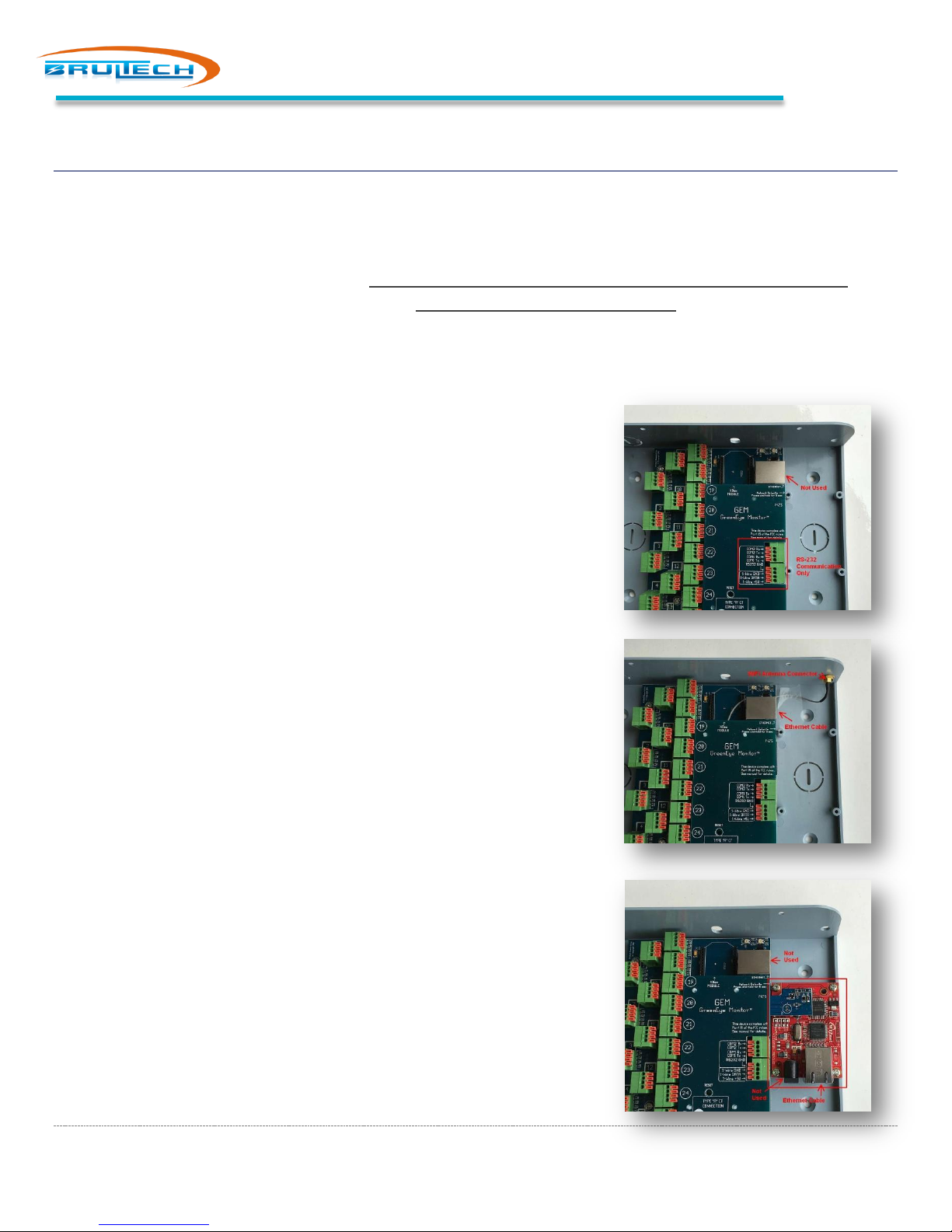
in your GreenEye Monitor: “GEM”, “GEM-WE” or “GEM-E”
Base model “GEM”
Strictly uses RS-232 for communication with the DashBox or other
data host. All GEM devices have RS-232 by default.
This model is identifiable by the fact that there is no antenna
connector such as “GEM-WE” model and the lack of the additional
reddish circuit board like the “GEM-E”. See picture on the right.
Introduction
WiFi/Ethernet “GEM-WE”
Has the option of WiFi, Ethernet or RS-232 for communication with
the DashBox or other data host.
You can easily identify this model by the presence of a WiFi antenna
connector. See picture on the right.
Ethernet Only “GEM-E”
Has the option of Ethernet or RS-232 for communication with the
DashBox or other data host.
This model is easily distinguishable by the presence of the reddish
colored circuit board installed. Notice that the Ethernet connection
is done on the module and NOT the jack on the blue GEM board.
Additionally, the black barrel jack on the module is not used or
functional.
Page 3
Page 5
Important Safety Information
Read All Safety Rules Before Installing!
IMPORTANT SAFETY INFORMATION
WARNING !
All safety rules described below must be obeyed. Read safety information carefully before proceeding with the
installation of the GreenEye Monitor and associated current transformer.
The GREENEYE MONITOR (GEM) is a low voltage device. This requires that all external connected signals be a low
voltage (<50V) and provided by Class II approved power supply.
All of our power supplies are UL, CSA or UL/c approved for use in USA and Canada. Our current
transformers (CT) are UL/c listed. No direct line connections to the GEM are allowed. All signals
must be galvanic isolated from the power-line.
Never install the GEM inside an electrical panel. A separate “low voltage” panel may be used when needed.
The GREENEYE MONITOR (GEM) installation requires the installation of current transformers (CT) installed inside the
electrical service panel. This portion of the installation MUST be performed by a qualified electrician or individual. The
installer must follow all local safety codes and use proper safety practices and equipment.
The qualified installer must be aware that main panels may still contain dangerous voltage levels even though the main
breaker is in the “OFF” position.
The following rules MUST be obeyed!
Any work performed inside the electrical panel must be done by an electrician or qualified individual. This
individual will be familiar with the local electrical code and perform the installation accordingly.
NEVER install the GreenEye Monitor (GEM) inside the electrical panel. Only low voltage (12VAC or less)
galvanic isolated connections are to be made to the GREENEYE MONITOR (GEM) terminals.
The current transformer (CT) leads must exit the electrical panel through an appropriate box connector, strain
relief or bushing. The CT leads must be properly anchored on the outside of the panel.
The portion of the CT leads inside the panel must not have any damage, cuts or wear to the outside
insulation.
The CT leads inside the electrical panel must be routed in such a way that its insulation will not be rubbing
against live terminals. Care must be exercised not to pinch the CT leads especially when re-installing the panel
cover.
Do not install the CTs in panels with voltages greater than 300V.
Do not install the GREENEYE MONITOR (GEM) in a wet location.
Page 4
Page 6
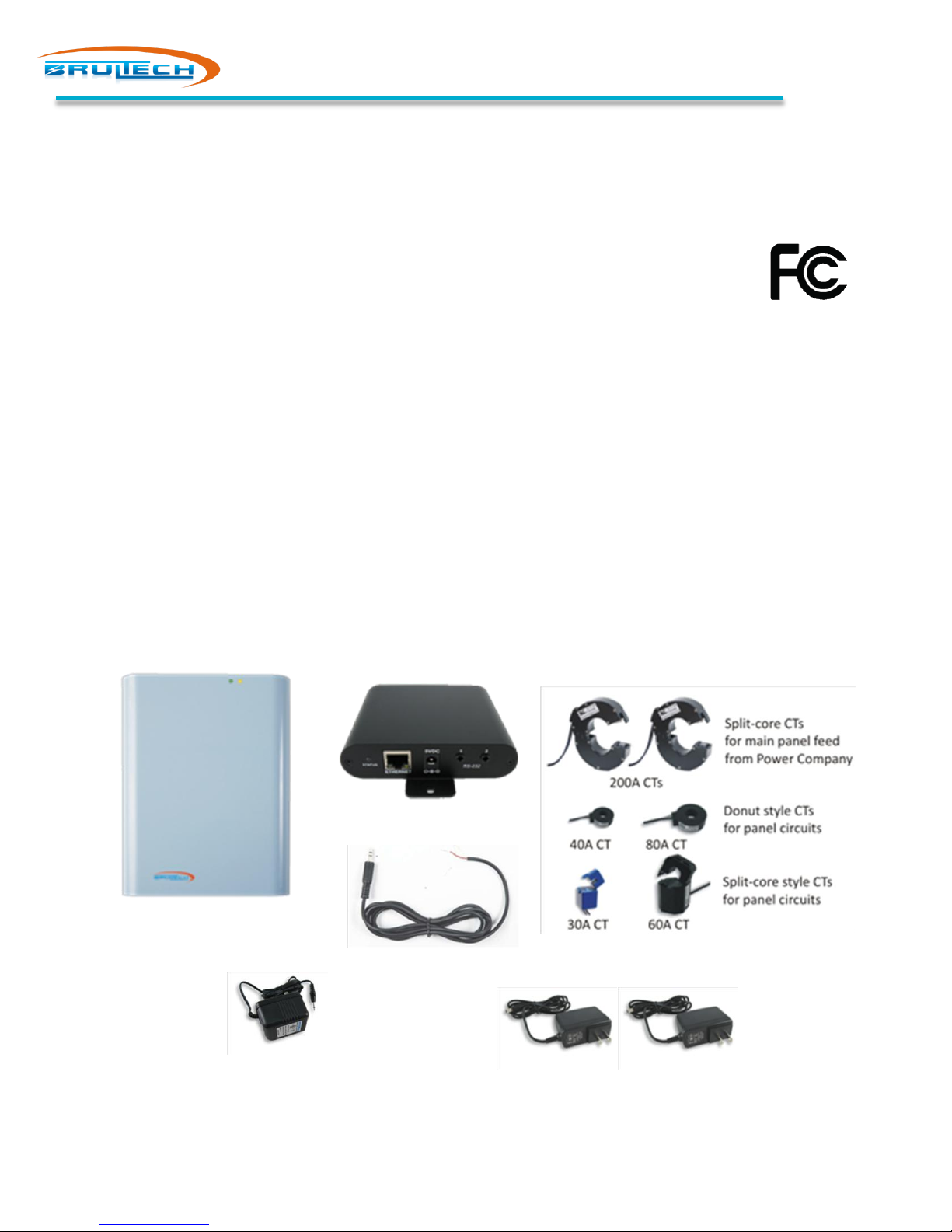
STS Cable
GreenEye Monitor
CT Model and Quantity Depends on System
12Vac Wall Transformer (PT)
Two 5Vdc Power Adaptor
COMPLIANCE
FCC COMPLIANCE
The GreenEye Monitor models GEM-W and GEM-E have been tested to Comply with FCC
Standards for Home and Office Use. The processor board inside the DashBox has also been tested
to comply with FCC Part 15.
This device complies with Part 15 of the FCC Rules. Operation is subject to the following two conditions:
(1) this device may not cause harmful interference, and
(2) this device must accept any interference received, including interference that may cause undesired
operation.
Wireless Versions:
Contains FCC ID: OUR-XBEE2 (USA) (Wireless Versions Only)
Contains Model XBee® ZNet 2.5 Radio, IC: 4214A-XBEE2 (Canada)
May Contain Roving Networks WiFly Module FCC ID: T9J-RN171
May Contain FCC ID: AZYHF-A111
Compliance
WHAT’S IN THE PACKAGE
DashBox
Page 5
Page 7
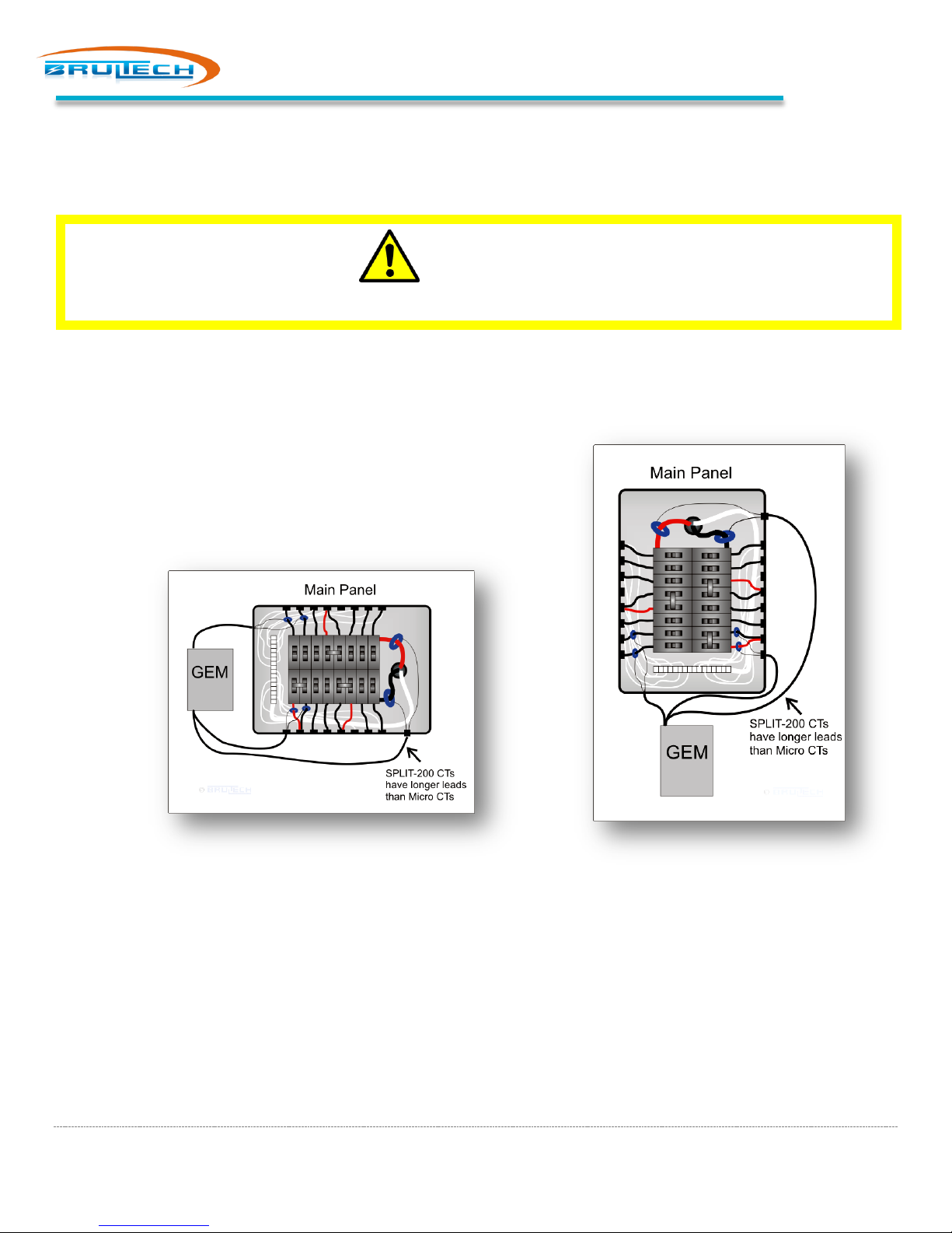
GEM Mounting Location
NEVER Install the GREENEYE MONITOR (GEM) Unit Inside the Electrical Panel
GEM MOUNTING LOCATION
Find suitable mounting location for the GEM. Do not mount the GEM inside breaker panel!
WARNING !
Make sure the CT lead will reach the furthest circuit breaker.
Determine the best mounting location for the GEM taking into consideration the length of the CT leads. Some CT models
have longer leads than others. The two large main panel CTs such as
SPLIT-100 or SPLIT-200 have longer leads than Micro-CTs do, so it may
be preferable to locate the GEM at the opposite end of the panel feed
where the large CTs are installed. See diagrams below.
Page 6
Page 8
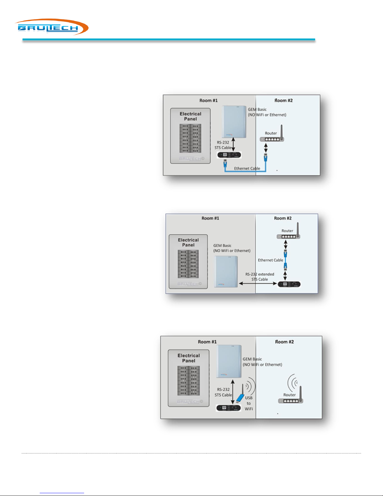
DashBox Location
The DashBox is located within two feet from the GEM
DashBox is located a distance from the GEM by extending the STS Cable
The DashBox is located near the GEM and connects using WiFi
DASHBOX LOCATION
The possible location for the DashBox depends on the GEM’s communication options (if any) installed. All GEM models
have RS-232 ports and qualify for “Option 1”. This option is recommended because it allows the DashBox to collect data
independent of the network status or even without a network.
OPTION 1: RS-232 CABLE
(RECOMMENDED)
Model: GEM / GEM-WE / GEM-E
This option uses RS-232
communication between the GEM and
the DashBox. All GEM models are
compatible with option.
The STS Cable is 3 feet long therefore
the DashBox should be mounted
within two feet of the GEM.
The STS cable may be extended to
allow the DashBox to be located in
another room. It is recommended to
use CAT 5 or CAT 6 network cable to
extend the RS-232 STS cable.
Page 7
Page 9
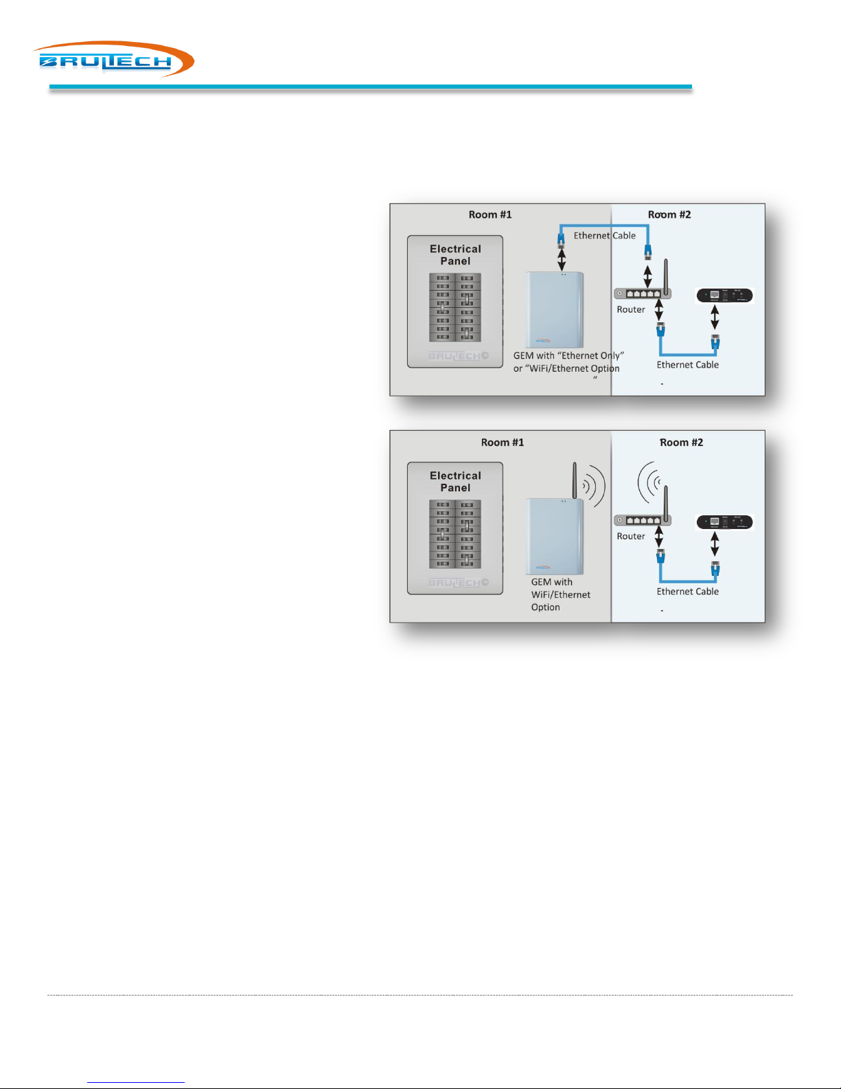
OPTION 2: TCP CONNECTION
Model: GEM-WE / GEM-E
Option 2 uses the network as the path for data
from the GEM to be sent to the DashBox. This
option is only possible with GEM models listed
above.
The GEM can be connected to the network via
Ethernet Cable or in the case of WiFi/Ethernet
GEM models, WiFi connected.
Option 2 is not as reliable as Option 1 which
consists of an RS-232 connection since any
network downtime will affect data collection.
NOTE: GEM-E is not capable of WiFi connection.
DashBox Location
Page 8
Page 10
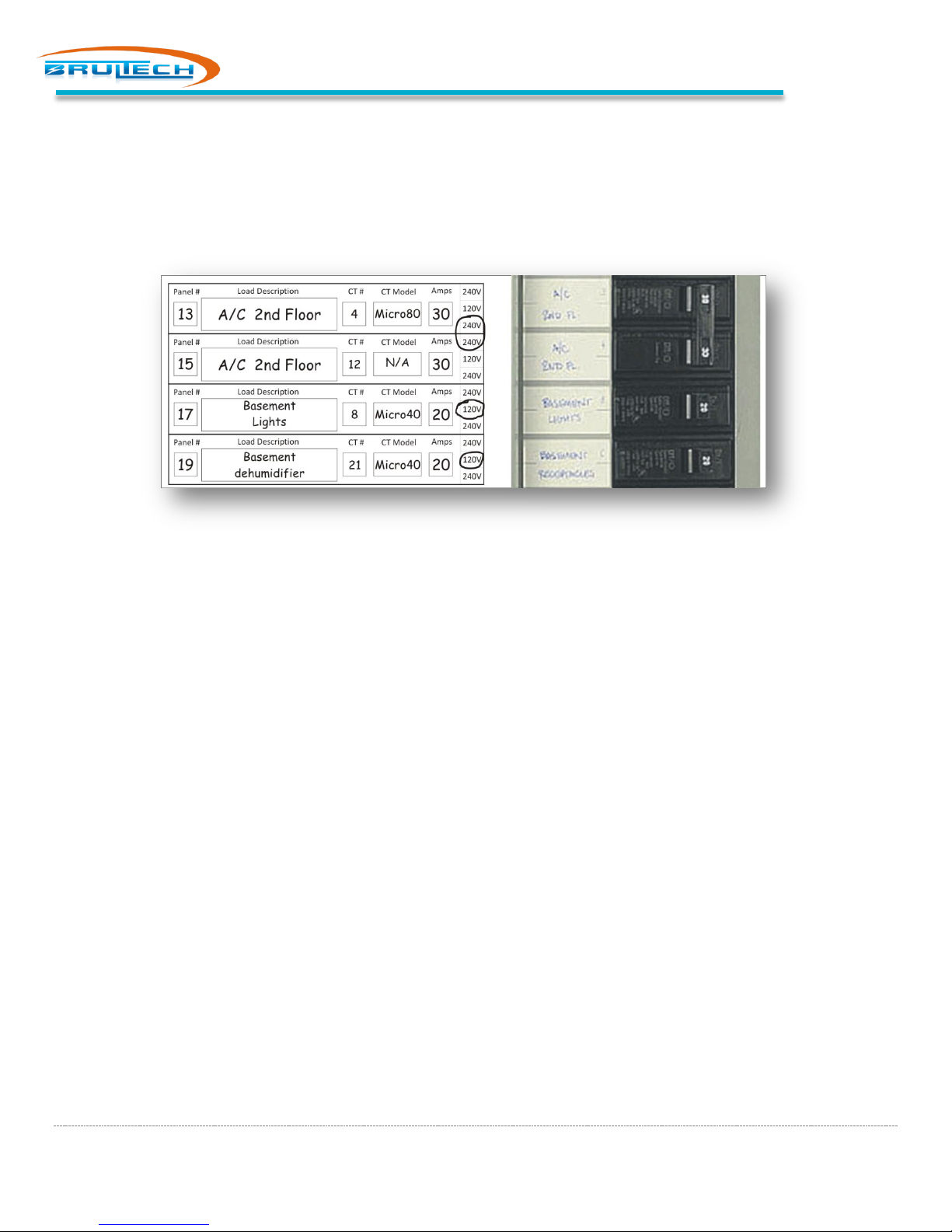
PANEL LAYOUT
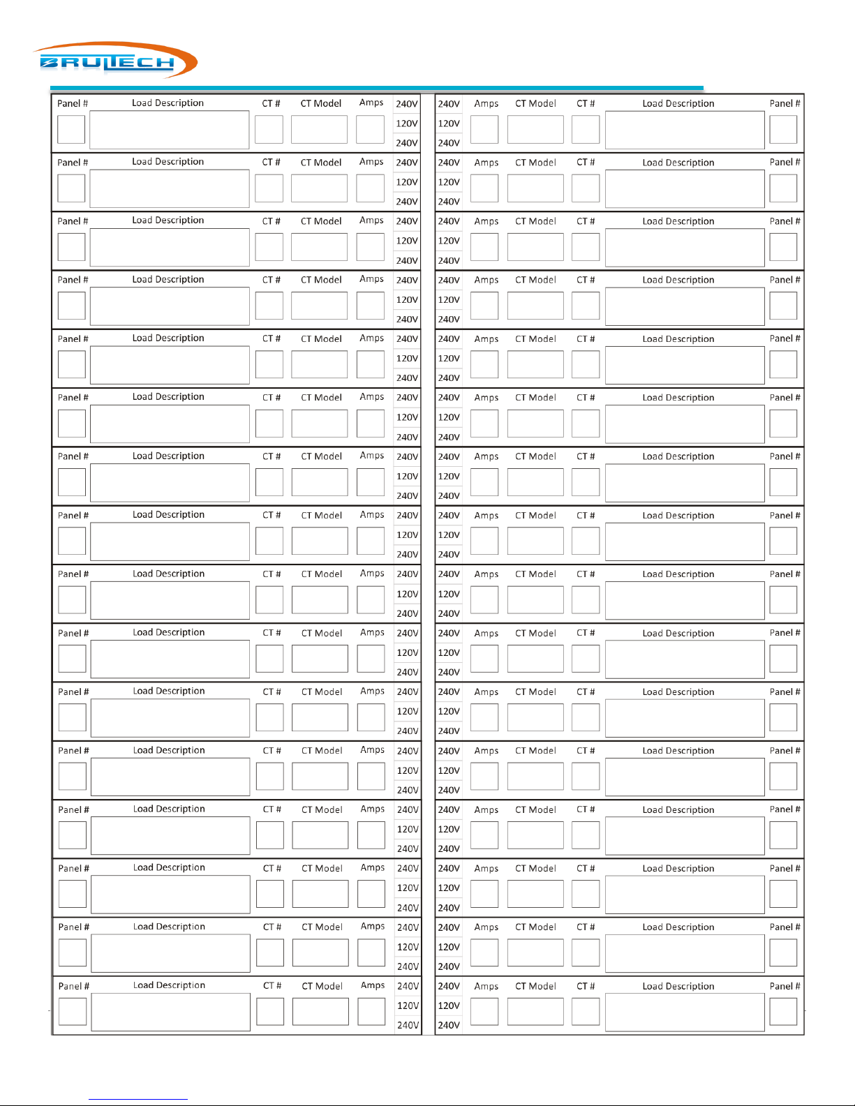
A generalized panel layout sheet is located on the last page of this document. Print a copy and fill in the information for
each breaker. This will greatly simplify setting up the GEM CTs and DashBox channels later. Each field is defined below.
The picture (below) shows part of the channel info sheet on the left and a section of breakers represented.
FIELDS
Panel #
Load Description
CT #
CT Model
“Panel #” is the breaker slot number on the panel itself
“Load Description” is the name of the appliance, outlet, light, etc. connected to this breaker
“CT #” is the number on the CT leads. This allows the installer to know which CT leads represent each
channel when it comes time to connecting the leads to the GEM.
Not all CTs have numbered labels attached. If this is the case, it is advisable to put a small piece of
masking tape at the end of the CT leads after the CT has been installed and the leads have been routed
outside of the panel
“CT Model” is the Brultech model number of the CT
Amps
“Amps” is the amperage rating of the circuit breaker
240V-120V-240V
Circle the voltage that represents the breaker. If it’s a 240V breaker it is typically coupled with a breaker
adjacent to it. In this case, circle the two together as shown in the picture above.
Page 9
Page 11
Read and understand the safety information before the CT installation!
CT INSTALLATION
WARNING !
Read the Important Safety Information chapter at the beginning of this document
before proceeding with CT installation!
CT ORIENTATION
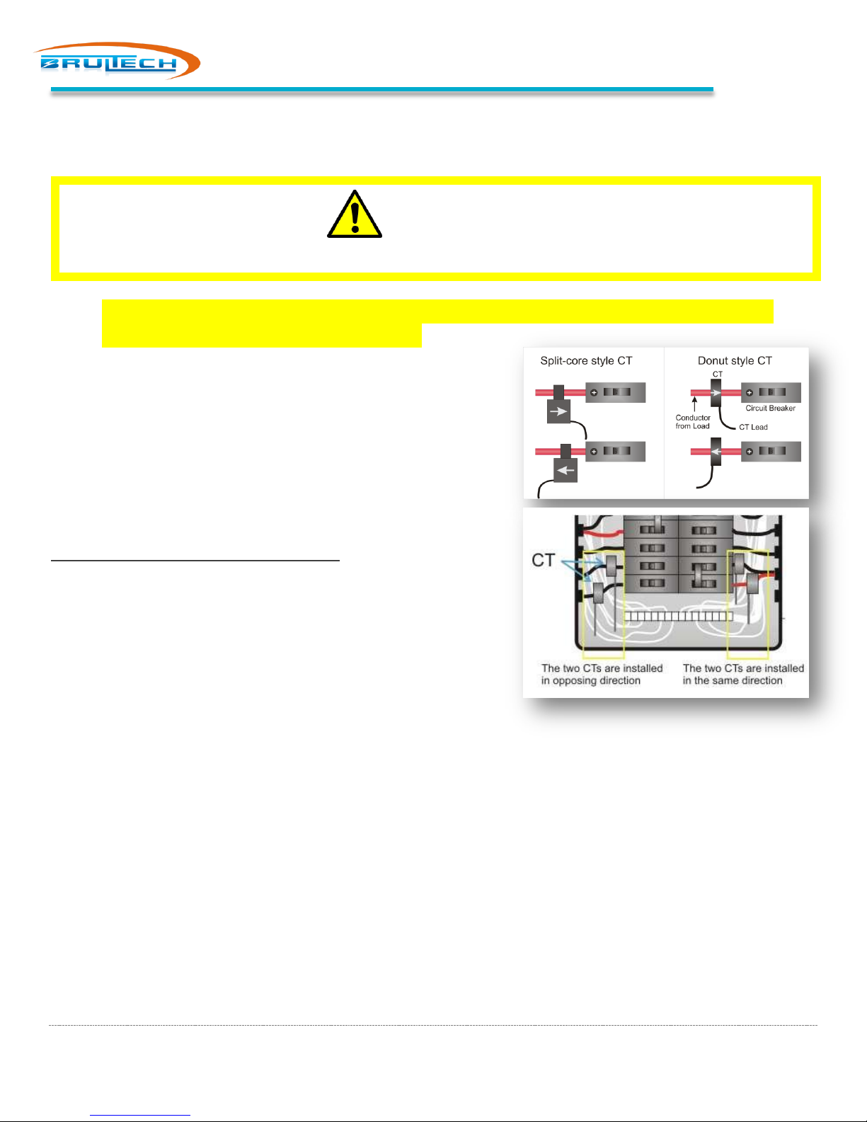
The CT orientation is best understood by looking at the picture on
the right. For each of the CT styles the CTs are shown mounted in
opposite direction.
Paying attention to the side of the CT where the leads exit, notice
that in one case this side faces toward the circuit breaker and in the
other case, away from the breaker.
If only one CT is connected to a given channel, the GEM doesn’t care
about orientation.
All CTs may be installed in any direction but once the CTs have been
installed, make note of the CT orientation for both CTs when two CTs
are connected to a 240V load to be monitored by a single channel.
CT Installation
240V LOADS
You can monitor a 240V load with only one CT if the load is balanced.
A balanced load is one that does not use a neutral conductor
therefore the current which flows through one line is identical to that which flows through the other. If you are not sure
if the load is balanced, use two CTs. If using a single CT for the 240V load, orientation is irrelevant.
Typical 240V Balanced Loads
Central air condition system, water heater, baseboard heater, water pump
Typical 240V Unbalanced Loads
Clothe dryer, electric range
ROUTE THE CT LEADS
Neatly route all of the CT leads through one of the many “knock-out” holes of the GEM enclosure. In some installations,
the leads may enter the GEM through the back of the GEM enclosure.
Page 10
Page 12
CT Termination
CT TERMINATION
GEM TERMINAL STRIPS
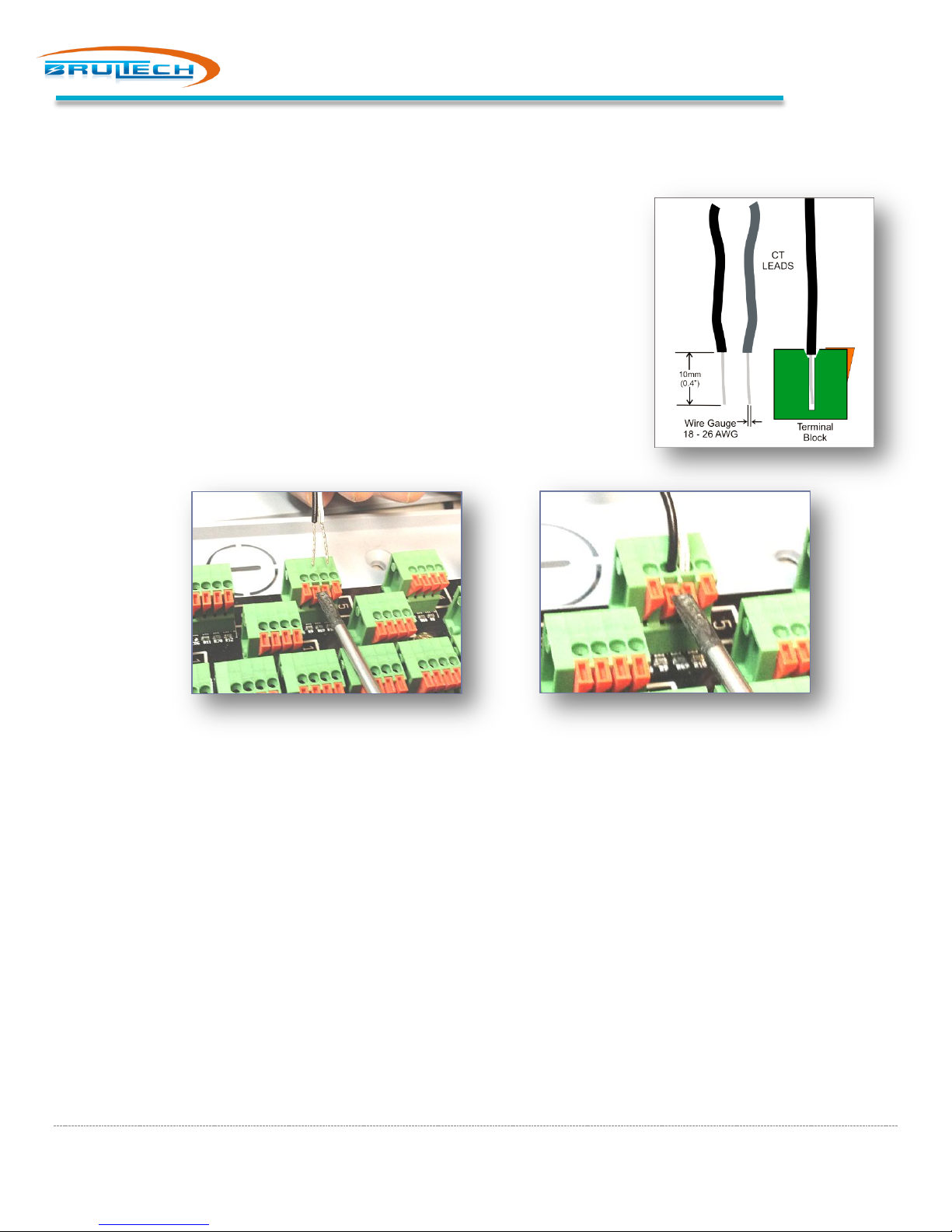
NOTE: The CT leads must be stripped approximately 10mm (0.4”) and have a
gauge size between 18 and 26 AWG.
The GEM uses spring loaded terminal blocks. The CT leads must be stripped the
proper length. If the leads have stranded wire, it is preferable to “tin” the wire
beforehand to prevent dealing with frayed ends. (Tinning is the process of
adding solder to bond all of the strands together).
The CT leads are inserted into terminal block while pressing down on the
corresponding orange tab (see picture below).
1. Align the two lead ends with the terminal holes. This can be done one lead at a time however it may be easier
inserting both leads at the same time, providing they are tinned with no frayed ends.
2. Press down on the orange TAB(s) corresponding to the lead or leads to be inserted, using a small “flat blade”
screwdriver.
3. Insert the leads into the terminal block while making sure the leads are perpendicular. In most cases, both CT
leads can be inserted at the same time. If the lead was stripped back 10mm, then the stripped section should be
entirely inside the block with only the insulation visible.
4. Release the pressure to the spring tab.
5. Finally, tug slightly on the leads to make sure they are secure.
Page 11
Page 13
CT TERMINATION
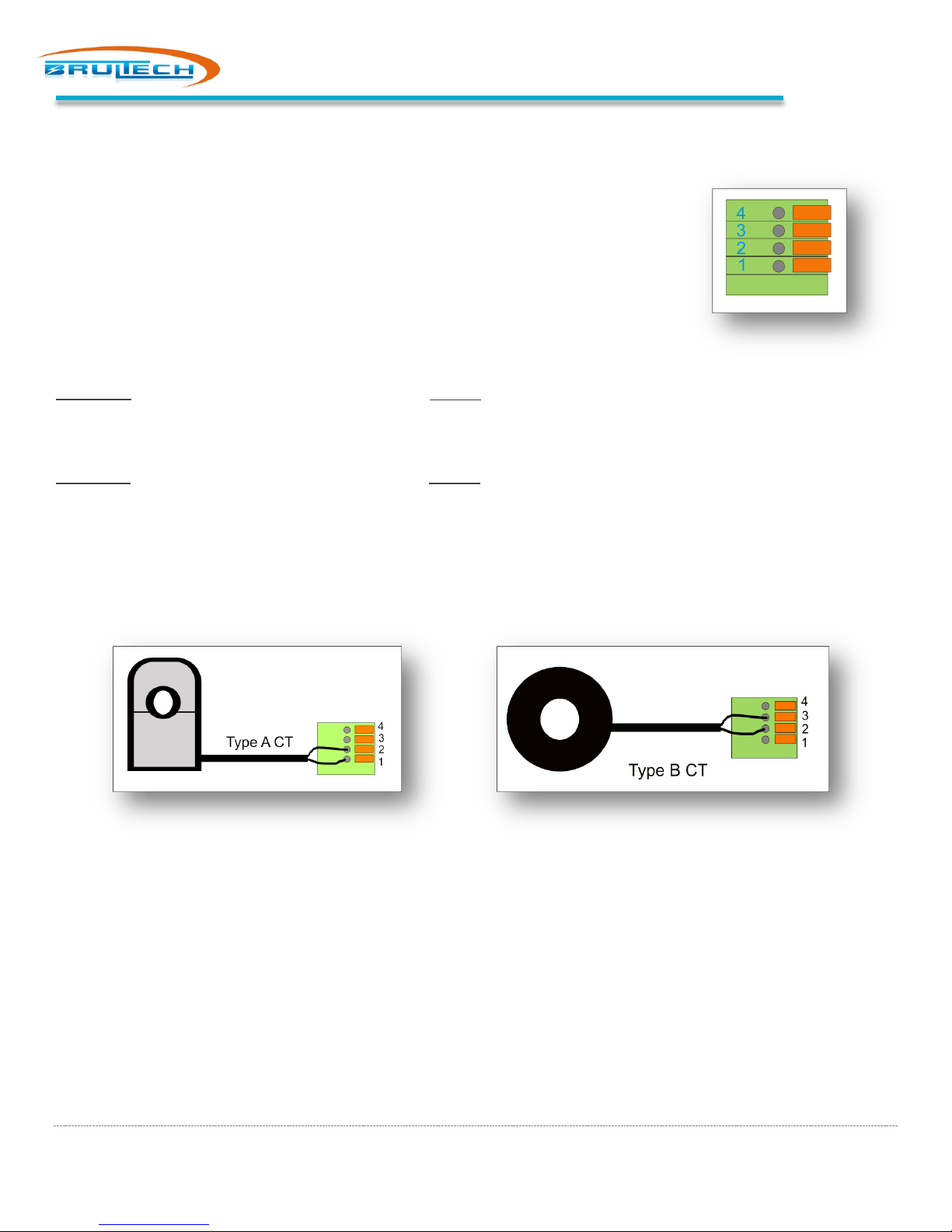
The picture on the right shows the terminal block. Each block has four terminals.
Terminal 1 is at the bottom. The terminals that the CT will be connected to are
dependent on the type of CT used.
Two types of current transformers are used with the GEM: Types A and Type B.
The difference between each type has to do with the type of signal which represents the
sensed current:
TYPE A CT: The measured current is represented by a voltage output signal.
(SPLIT-60, SPLIT-100, SPLIT-200, SPLIT-400/600, SPLIT-170)
TYPE B CT: The measured current is represented by a current output signal.
(Micro-40, Micro-50, Micro-80, Micro-100)
CT Termination
SINGLE CT CONNECTION
When only one CT is connected to the GEM it doesn’t matter which color lead goes to each terminal.
Page 12
Page 14
CT Termination
CONNECTING TWO CTS ON ONE CHANNEL
Two Type “A” CT Connection
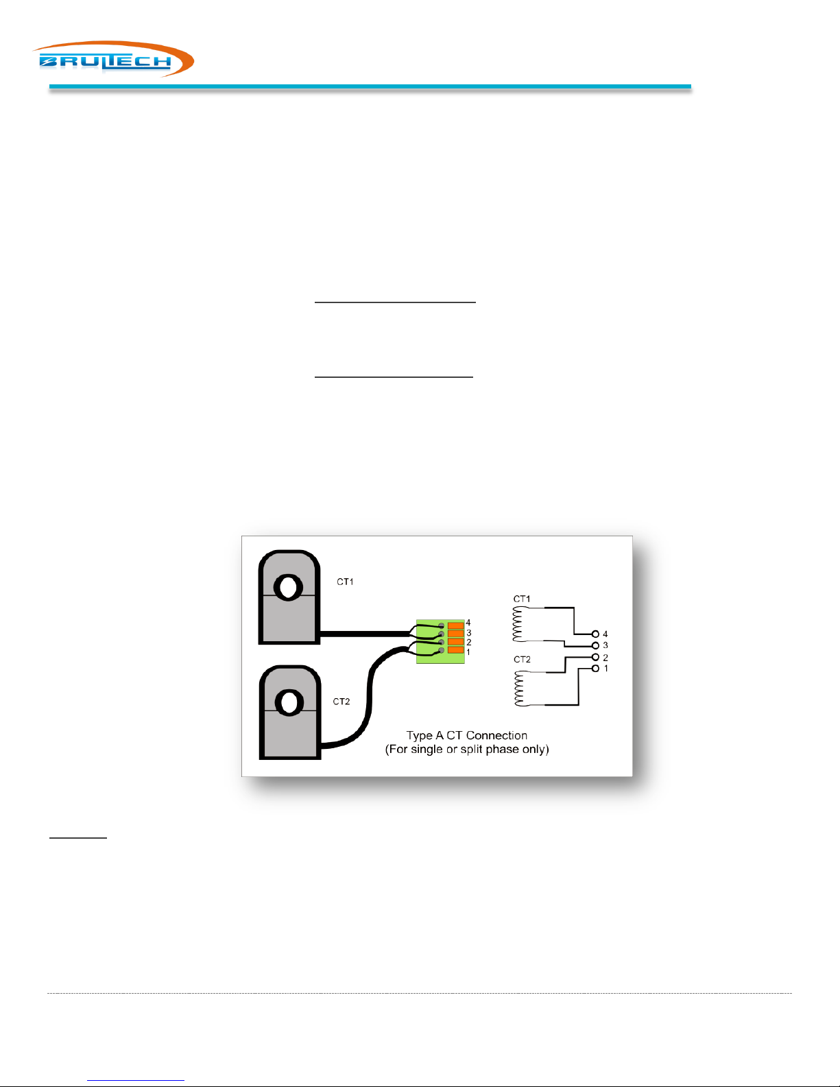
The following CT models are “Type A”: SPLIT-30, SPLIT-60, SPLIT-100, SPLIT-200, SPLIT-400/600, SPLIT-170
When connecting two CTs to a given channel, the CT orientation and lead color needs to be taken into account to
prevent the signal of one CT from subtracting from the other.
When two CTs from a 240V load are connected to the GEM as shown in the diagram to the right, the rule for the CT lead
color code is as such:
If the two CTs are installed facing opposite directions:
Terminals 1 & 3 will have the same color lead
Terminals 2 & 4 will have the same color lead
If the two CTs are installed facing the same direction:
Terminals 1 & 4 will have the same color lead
Terminals 2 & 3 will have the same color lead
This rule is based on a 240V load which means that one CT is on phase A and the other on phase B.
If both CTs are connected to two different loads which happen to be on the same phase, then the rule described is the
opposite!
Example:
Two SPLIT-200 CTs are connected to the main feeder. They are installed with both CTs facing the main panel
breaker.
The solid black lead of CT#1 is connected to terminal #1 and the other lead to terminal #2
The solid black lead of CT#2 is connected to terminal #4 and the other lead to terminal #3
Page 13
Page 15
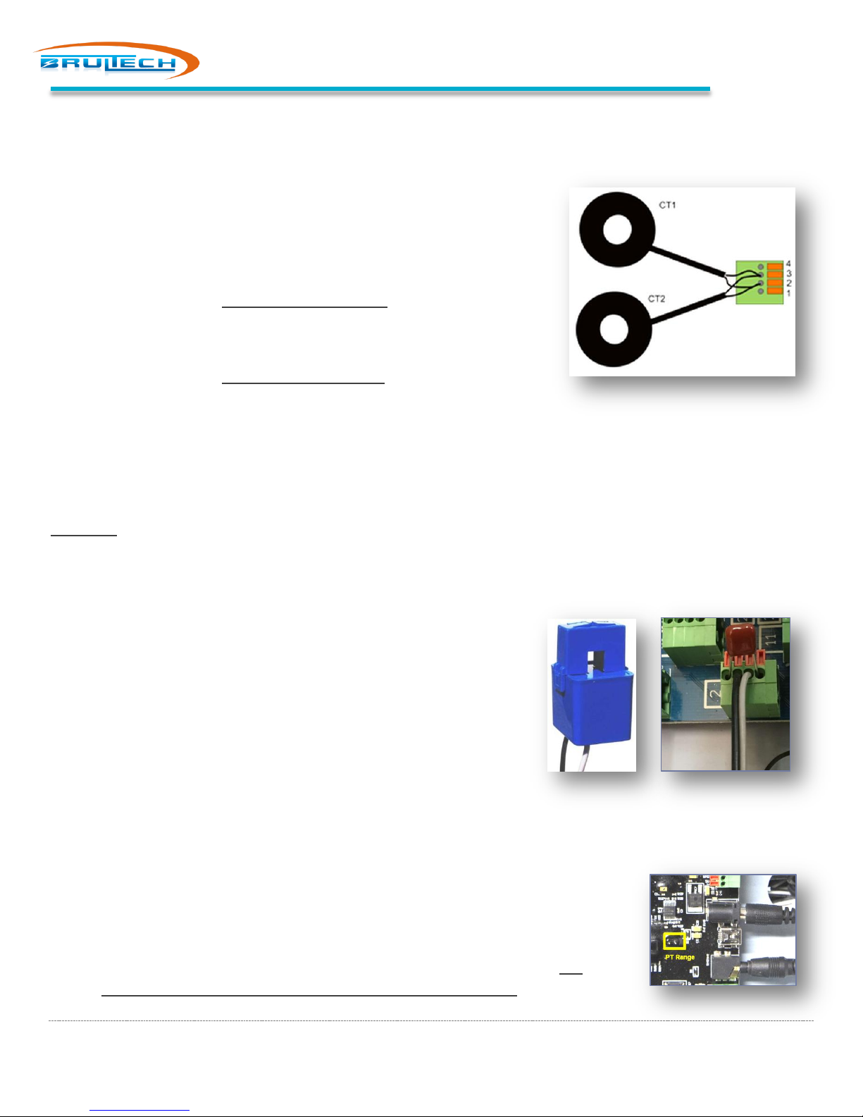
Power Supply and Wall Transformer
Two Type “B” CT Connection
The following CT models are “Type B”: Micro-40, Micro-50, Micro-80,
Micro-100
When two CTs from a 240V load are connected to the GEM as shown in the
diagram to the right, the rule for the CT lead color code is as such:
If the two CTs are installed facing opposite directions:
Terminals 2 will have the same color lead from each CT
Terminals 3 will have the same color lead from each CT
If the two CTs are installed facing the same direction:
Terminals 2 will have dissimilar color lead from each CT
Terminals 3 will have dissimilar color lead from each CT
This rule is based on a 240V load which means that one CT is on phase A and the other on phase B.
If both CTs are connected to two different loads which happen to be on the same phase, then the rule described is the
opposite!
Example: Two Micro-80 CTs are connected to the electric stove. They are installed with both CTs facing the breaker.
The white lead of CT#1 and the black lead from CT #2 are connected together to terminal #2
The black lead of CT#1 and the white lead from CT #2 are connected together
to terminal #3
SPLIT-30 CT Connection
The SPLIT-30 is a “Type B” CT and the connection method for Type B
described above applies.
The only difference is the addition of a capacitor inserted in terminals 1
and 4.
POWER SUPPLY AND WALL TRANSFORMER
Plug the 5Vdc power supply and the 12Vac wall transformer into a receptacle near the
panel.
1. Plug the 5Vdc cable into the barrel jack (top right of picture)
2. Fully plug the 12Vac cable into the 3.5mm jack (bottom right of picture). It is
absolutely important to make sure that the plug is fully inserted!
Page 14
Page 16
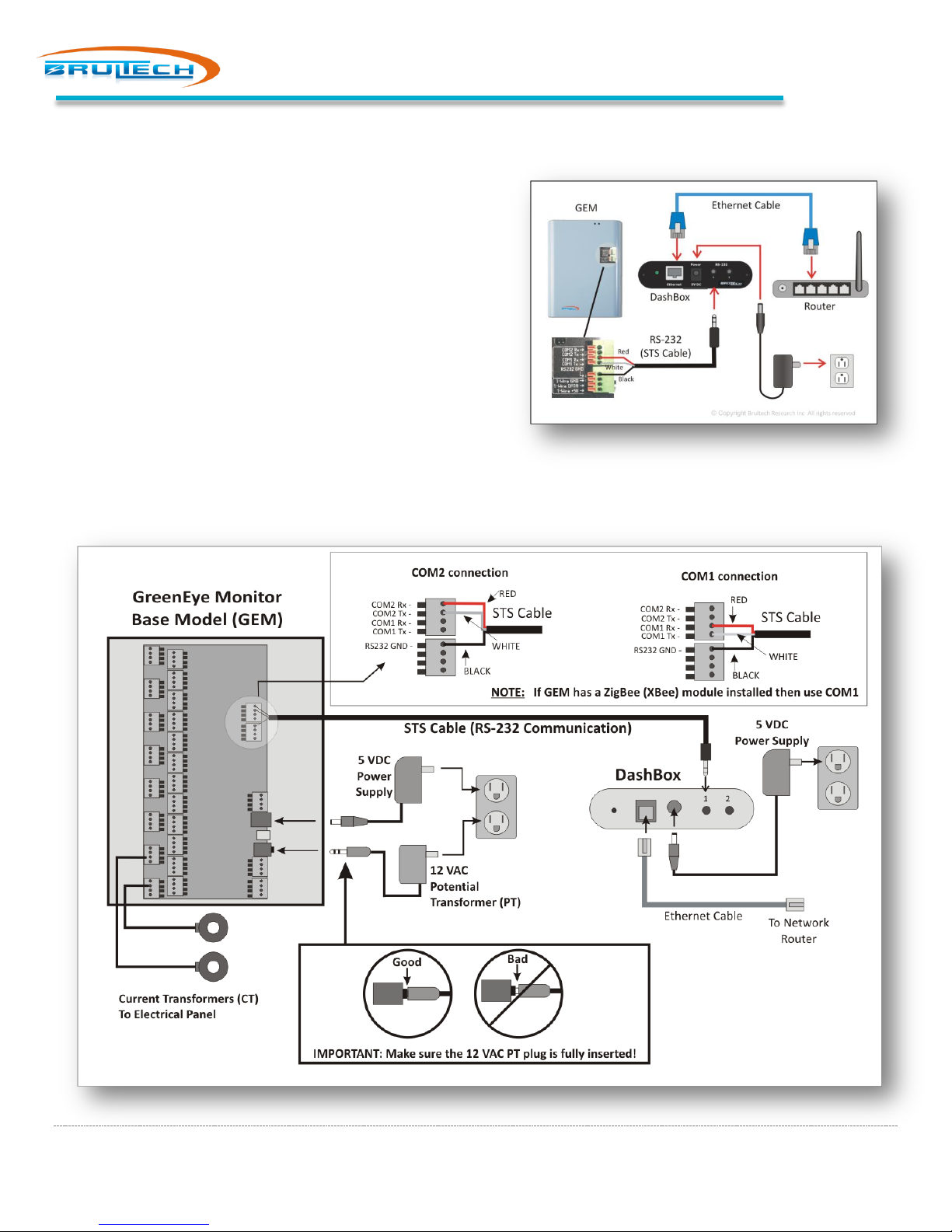
COMMUNICATION
Choose one of the following communication options: RS-232, Ethernet or WiFi
RS-232 CABLE INSTALLATION
Model: GEM / GEM-WE / GEM-E
For GEMs with WiFi/Ethernet or Ethernet only option, connect
the STS Cable (RS-232 cable) to COM 2 otherwise use COM 1
for basic GEM model.
1. Connect the STS Cable terminals to the GEM
a. Red wire to GEM’s Rx terminal
b. White wire to GEM’s Tx terminal
c. Black wire to GND terminal
2. Plug the STS Cable 3.5mm plug into port #1 of the
DashBox
3. Connect an Ethernet Cable between the DashBox and
the Network Router
Communication
Page 15
Page 17
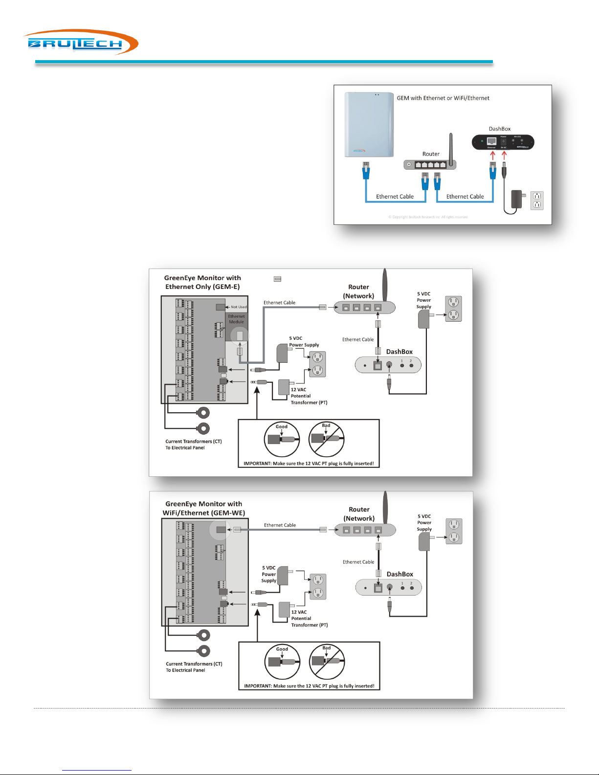
ETHERNET CABLE COMMUNICATION
Model: GEM-WE / GEM-E only
1. Connect an Ethernet Cable between the GEM and the
Network Router
2. Connect an Ethernet Cable between the DashBox and
the Network Router
Two GEM models have an Ethernet connector. The GEM-E
(Ethernet Only model) has an additional circuit board installed
and a dedicated Ethernet jack. The GEM-WE (WiFi/Ethernet
model) has no additional circuit board but does have a WiFi
antenna connector. Its Ethernet jack is on the GEM board.
Communication
Page 16
Page 18
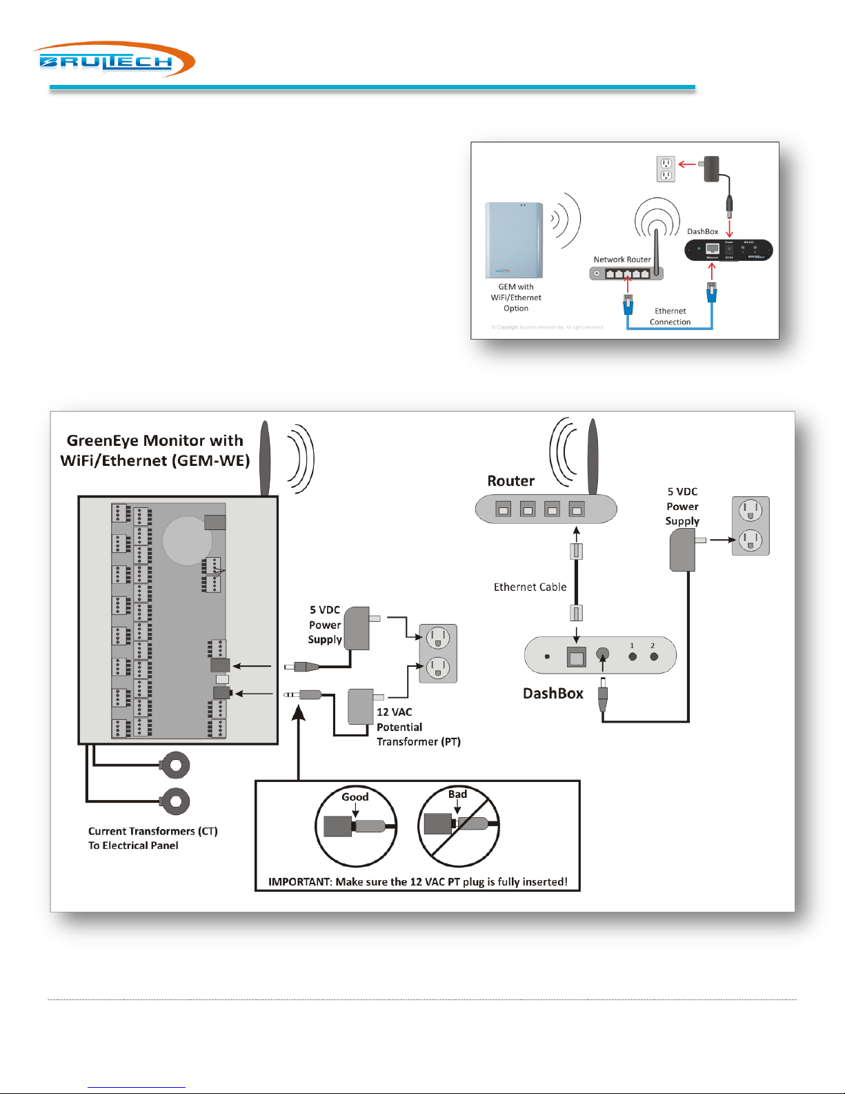
WIFI COMMUNICATION
Model: GEM-WE only
1. Connect an Ethernet Cable between the DashBox and
the Network Router
The procedure to establish a wireless connection is
explained later in this manual.
Communication
Page 17
Page 19
DashBox Setup
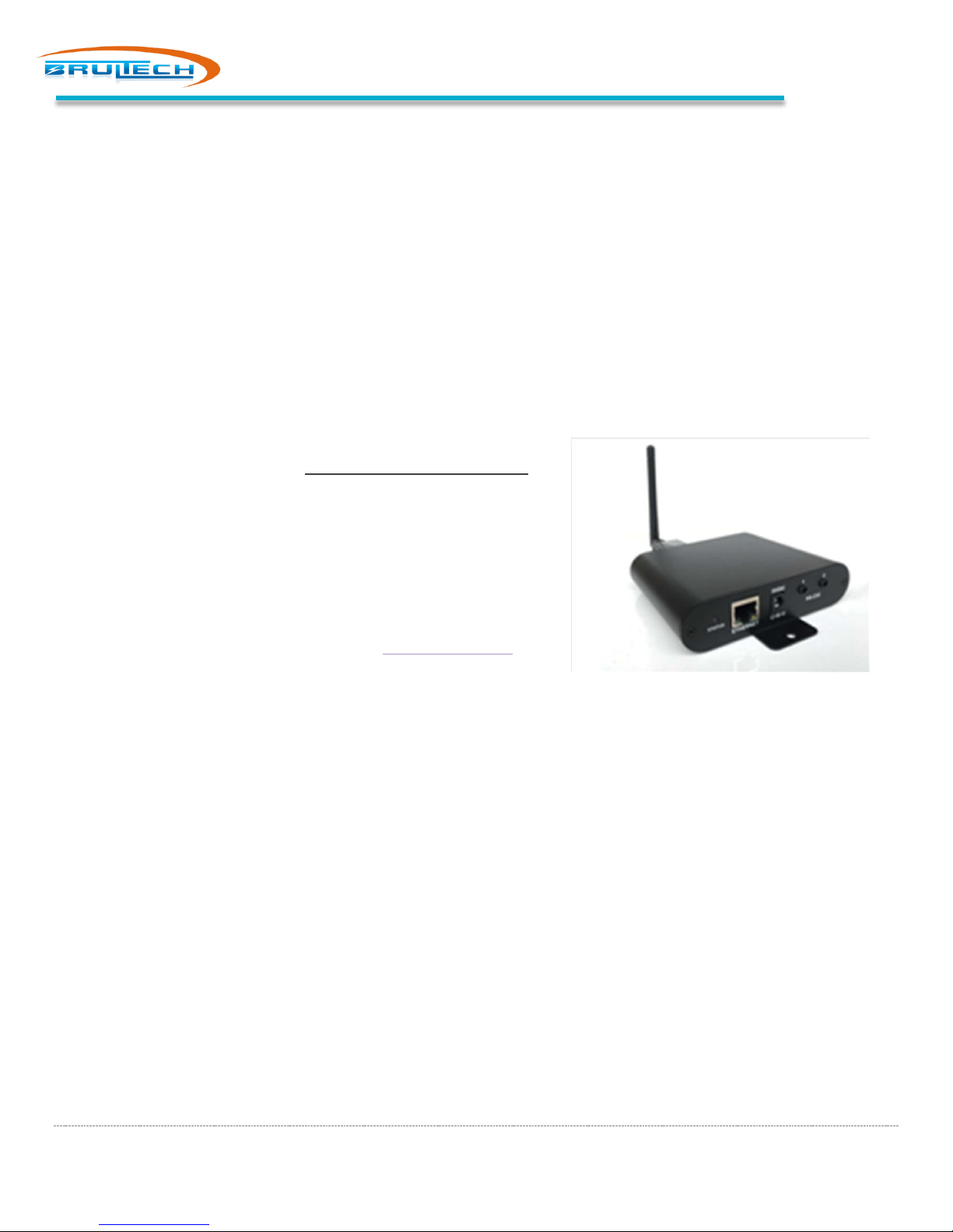
DashBox with Optional USB-WiFi Adapter
using the AR9271 chipset
DASHBOX SETUP
DASHBOX POWER UP
1. Connect a network cable between the network router and the DashBox
2. Connect the 5Vdc power supply adapter to the DashBox then plug it into a local receptacle
3. Observe the LED color sequence:
a. Reddish/pink glow for several seconds indicating that the system is booting up
b. Red flashing LED for 30 seconds while the super-capacitor charges
c. Green flashing LED for a few seconds while the system starts all processes
d. Green solid. System is started and ready
DASHBOX WIFI ADAPTER SETUP
If the DashBox is connecting to the network via Ethernet Connection
then proceed to the next chapter: “Locate DashBox on the Network”.
By default the USB/WiFi adapter will be in “Access Point” mode.
1. Make sure the DashBox has booted up with the USB/WiFi
adaptor plugged into the USB jack
2. Search and connect to the WiFi network named “DashBox…”
there may be a number following the name
3. Open your internet browser and enter http://192.168.6.1.
This will connect to the DashBox web interface
4. If this is the first time connecting to the DashBox:
a. Set your “Time Zone” and “Locale”
b. Assign the DashBox a login name and password
c. Set the rate in $ per kilowatt-hour (kWh). This can be
done by taking the total cost of the electric bill and dividing it by the total kWh used during the billing
period. If you’re in a rush, accept the default ($0.20) and change this later.
d. Read and accept the License Agreement
e. Click “Save Settings”
5. Click “Network” on the left side menu, then click “WiFi USB”
6. In the “Network Configuration” box, click the “Network Mode” radio button.
7. In the “Network” box, enter the name (SSID) of the wireless network you wish to connect to
8. Enter the password for the WiFi network in the “Password” box and select the security type from the “Security”
drop-down menu
9. Set “IP Type” to DHCP. This will allow the router to assign an IP address to the DashBox
10. Click the blue “Save Settings” button at the bottom. The system must be rebooted to take effect
11. Click “System” from the left menu then Click “Reboot System”
The DashBox will only work with TP-LINK TLWN722N wireless adaptor or any other type
Your computer should now disconnect from the Access Point since the DashBox is switch from Access Point to Network
mode. Connect to the network now to discover the DashBox which should now be connected to the WiFi network.
Page 18
Page 20
DashBox Setup
LOCATE DASHBOX ON THE NETWORK
The DashBox IP Address needs to be determined. If you are computer savvy and know how to discover the DashBox IP
Address from the network router go ahead and do so then skip to the next chapter “Set a Static IP Address”.
Windows users
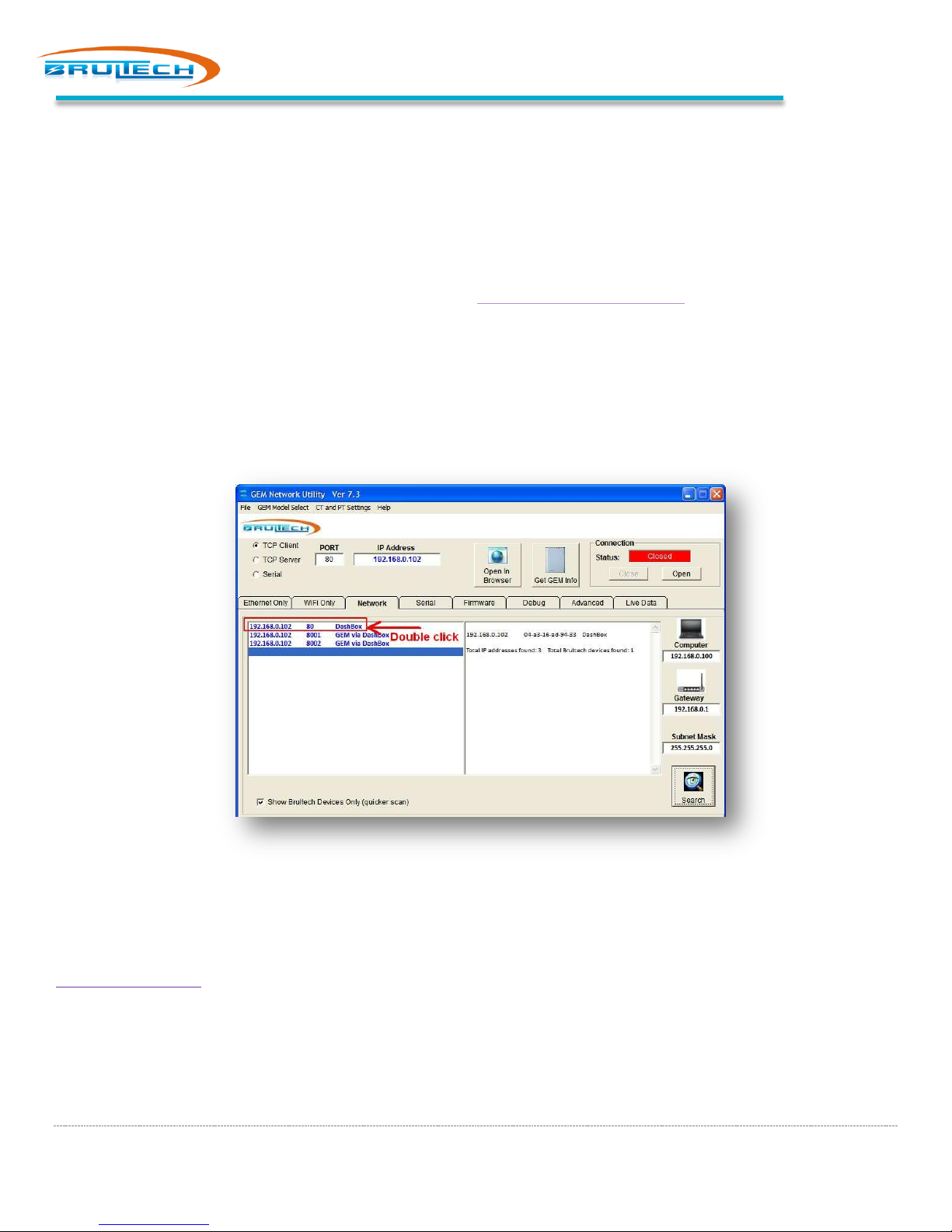
1. Download the “GEM Network Utility” program from http://brultech.com/software and install
2. Use “Run as administrator” option and start the program
3. Click the “Network” tab
4. Click “Search” on the bottom right
The “GEM Network Utility” will discover the IP address for the DashBox as shown below.
Double click on the IP address. This will open the DashBox web page in a browser.
Proceed to the next chapter “Set a Static IP Address”
Mac or Linux users
If you are using a Mac or Linux system, you can download a free “Network Scanner” program called Fing (
https://www.fing.io/ ) or you can connect to your router to view the devices on the network. Look for an IP address
associated with the name “TP-Link” (if you are using the USB to WiFi adaptor). Make note of the IP Address.
Enter this IP Address into your internet browser’s address bar then press “Enter”. This should take you to the DashBox
web page.
Page 19
Page 21
DashBox Setup
SET A STATIC IP ADDRESS
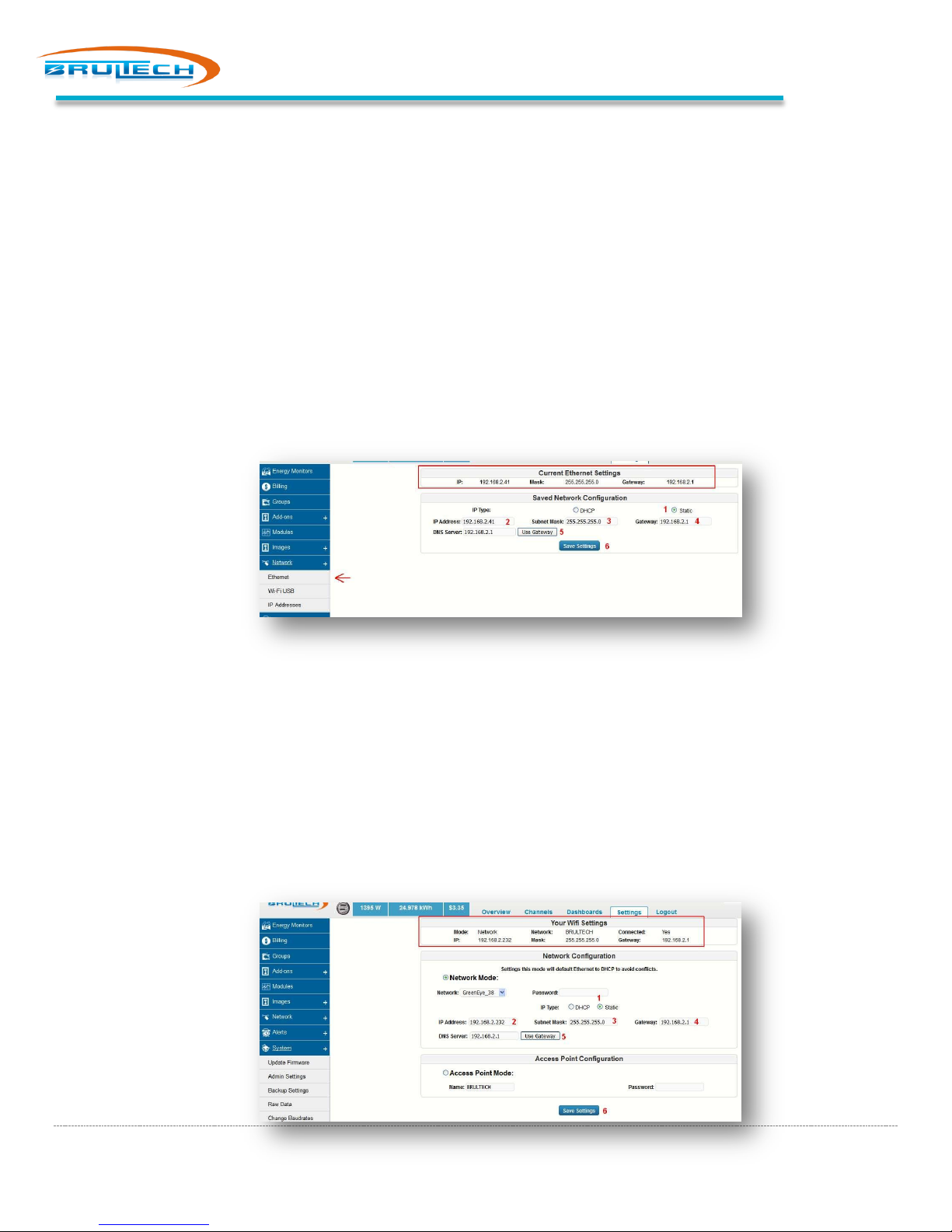
The DashBox network setting needs to be modified from “DHCP” to “Static” so that the assigned IP address doesn’t
change. Take note of this IP Address since this will be the set IP address used to view the Dashboards.
Ethernet Connected
Follow these steps if the DashBox is connected to the network using an Ethernet cable.
1. Make sure you are connected to the DashBox with your browser
2. Click “Network” on menu, then click “Ethernet”
3. Click the “Static” box (#1 in the screen shot below)
4. Using the values from the “Current Ethernet Settings” box enter the values in box 2, 3, 4 & 5
5. Click “Save Settings”
WiFi Connected
Follow these steps if the DashBox is connected to the network using a USB to WiFi adaptor.
1. Make sure you are connected to the DashBox with your browser
2. Click “Network” on menu, then click “WiFi USB”
3. Click the “Static” box (#1 in the screen shot below)
4. Using the values from the “Current Ethernet Settings” box enter the values in box 2, 3, 4 & 5
5. Click “Save Settings”
Page 20
Page 22

GEM Setup Page
GEM SETUP PAGE
The GEM has a browser based “Setup Page”. The procedure to access the “Setup Page” depends on the communication
method, RS-232 or via the TCP (network). Follow the steps (below) for the option that applies to you.
GEM CONNECTED VIA RS-232 (STS CABLE)
The “GEM Setup Page” is accessed using a browser and entering the DashBox IP address and appending a colon then the
port number. Use “:8001” if the STS Cable is plugged into port “1” of the DashBox or “:8002” if plugged into port “2”. For
example: “192.168.xx.xx:8001” if using port “1”.
GEM CONNECTED VIA NETWORK (ETHERNET OR WIFI)
Model: GEM-WE / GEM-E
If the GEM has the “WiFi/Ethernet” or “Ethernet Only” option, access to the GEM setup page is accomplished over the
network. The procedure varies depending on which of the two options (“WiFi/Ethernet” or “Ethernet Only”) is installed
on the GEM.
WiFi/Ethernet GEM
Model: GEM-WE
Determine whether to use WiFi or Ethernet for communication. Follow the instructions for your selected method.
Ethernet
Make sure that an Ethernet cable is connected between the Ethernet jack on the GEM and the network router.
By default, the GEM should connect to the router via DHCP.
Proceed to “View GEM Setup Page”.
WiFi
1. Search for wireless networks with your computer
2. Connect to the “GreenEye_xx” wireless network
3. Once connected to the network, open a browser and enter 1.2.3.4 or http://1.2.3.4 in the address bar
4. Use the “admin” for the user name and password to enter
5. Select “STA Interface Setting” from the menu
6. In the “STA Interface Parameters” box, click “Search”
7. After a few seconds, a box will open displaying the available WiFi networks available to connect to,
select a Network and provide “Security Mode” and “Passphrase” (password) for the WiFi network you
are connecting to
8. Click “Apply”
9. Select “Device Management” from the menu
10. Click “Restart”
Page 21
Page 23
GEM Setup Page
application (free)
Wait a few seconds for the module to reboot and connect to the network. In the meantime, connect to the
network with your computer.
View GEM Setup Page (WiFi/Ethernet)
Run the “GEM Network Utility” (Windows)
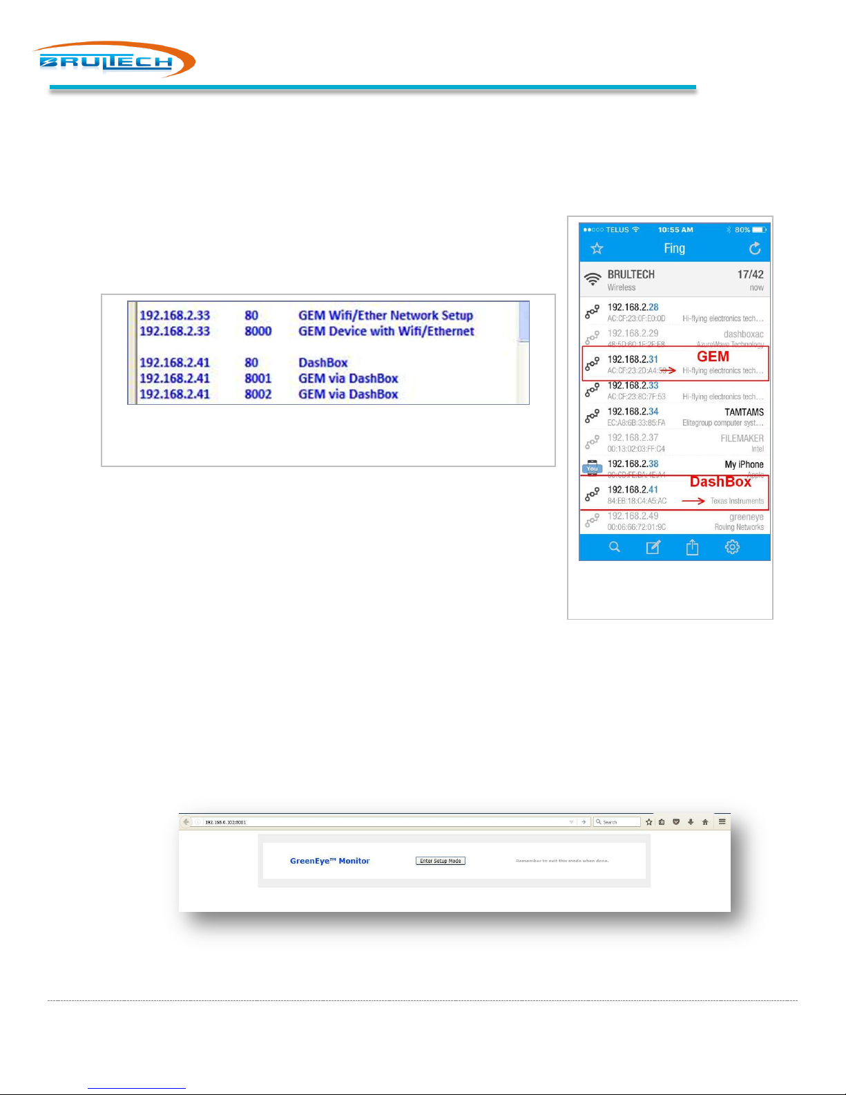
Click the “Network” tab then click the “Search” button
The program will find the GEM device and IP address as displayed below
Result from “Search” using the “GEM Network Utility” program
If a Windows computer is not available, download and install “Fing”
network tool or get the Fing App free (iOS & Android). Once installed,
perform a network scan.
The screen on the right shows an example of the Fing scan. The GEM
(WiFi/Ethernet model) is discovered based on the “Hi-Flying electronics”
device name. The DashBox is discovered based on the “Texas
Instruments” device name.
1. If using the “GEM Network Utility”, double-click the line displaying “GEM Device with WiFi/Ethernet”. If
using “Fing” or searching the router’s “Connected Devices”, look for “HiFlying Electronics Tech”. Use the
IP Address for this device and insert it into a browser’s address bar and append “:8000” to it. Ex:
192.168.2.33:8000
Result from using the “Fing”
You should now have the GEM’s “Enter Setup” page opened (screen shot below). You may need to refresh the
page a couple of times to open this page.
Page 22
Page 24
WiFi/Ethernet Reset to Factory Default
Model: GEM-WE
If you experience any problems or improperly configure the WiFi/Ethernet module, you can reset it to default
settings using the push button switch located just to the left of the network jack on the GEM’s circuit board.
Procedure to reset the module to factory default settings:
1. Press and maintain the switch for 5 or more seconds then release
2. Wait 15 seconds for the module to reboot itself after releasing the switch
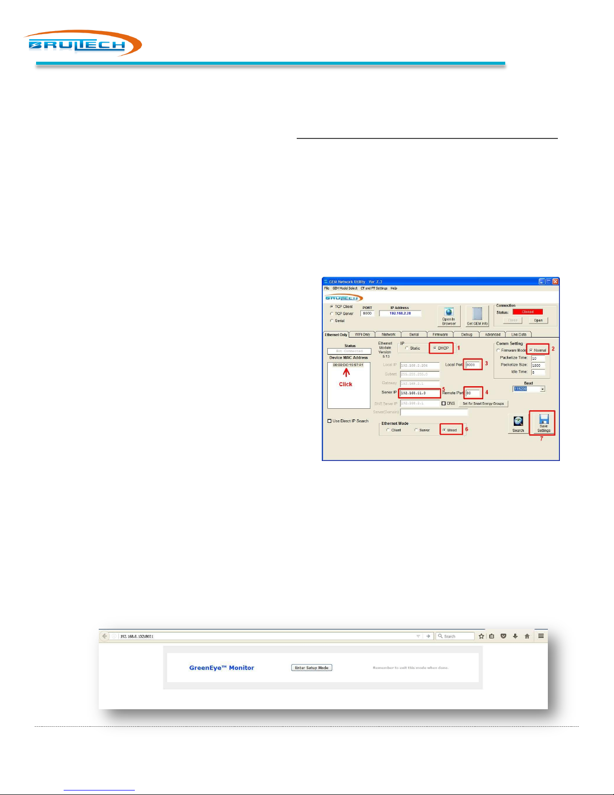
Ethernet Only GEM
Model: GEM-E
View GEM Setup Page (GEM with Ethernet Only)
a. Run the “GEM Network Utility” software (run
as administrator)
b. Click the “Ethernet Only” tab
c. Click “Search” (bottom right)
GEM Setup Page
1. Set to DHCP
2. Click “Normal” button
3. Set “Local Port” to “8000”
4. Set the “Remote Port” to “80”
5. Enter the IP Address of the DashBox into the “Server IP” box
6. Select “Mixed” option
7. Click “Save Settings”
Click the Mac Address in the “Device Mac Address” box then click “Open” (top right)
You should now have the GEM’s “Enter Setup” page opened (screen shot below). You may need to refresh the
page a couple of times to open this page.
Page 23
Page 25
GEM Setup Procedure
GEM SETUP PROCEDURE
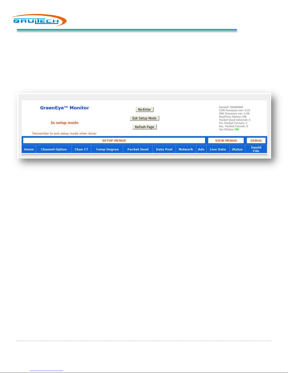
Based on the previous steps, the “GEM Setup” page should now be opened in your browser (see screen shot below).
Note: The GEM exits setup mode automatically after a few minutes so you may have to re-enter if there is too much idle
time between executing settings
CONFIGURING CTS
For each channel with a connected CT, you will enter the CT Model connected to it.
1. Click “Enter Setup Mode”
Note: The GEM exits setup mode automatically after a few minutes so you may have to re-enter if there is too much idle
time between executing settings. All settings are saved immediately when executed.
Refer to the screen shot below
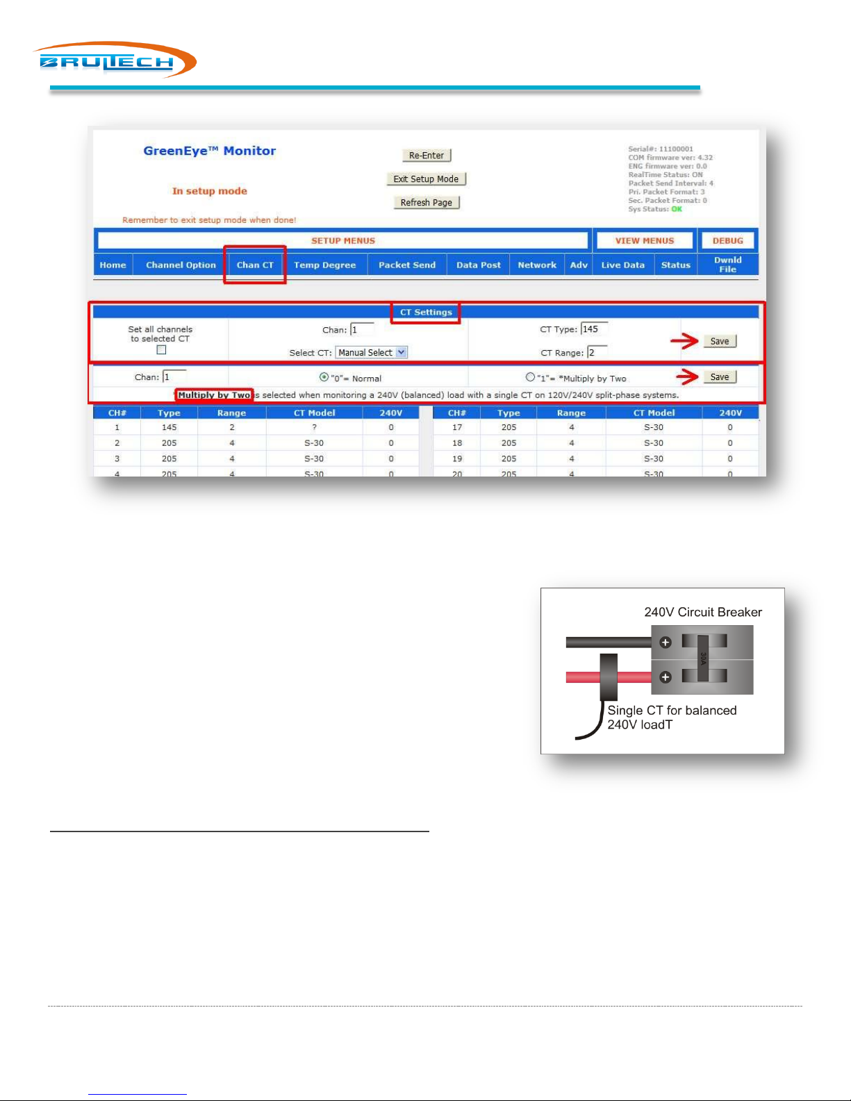
CT Settings
1. Click “Chan CT” from the menu
2. In the “CT Settings” box, enter the channel number
3. Select the CT model connected to the channel
4. Click “Save”
5. Repeat steps 2, 3, 4 for all connected channels
Page 24
Page 26
GEM Setup Procedure
The table below will refresh displaying the new CT model for the given channel.
Multiply by Two
If monitoring a 240V balanced load using only one CT instead of two (see
diagram on the right), use the “Multiply by Two” option.
1. Enter the channel number the single 240V CT is connected to
2. Click: “1”= Multiply by Two radio button
3. Click “Save” (within that same section)
HTTP POST SETUP
Model: GEM-WE / GEM-E
Skip this section if using RS-232 (STS Cable) communication.
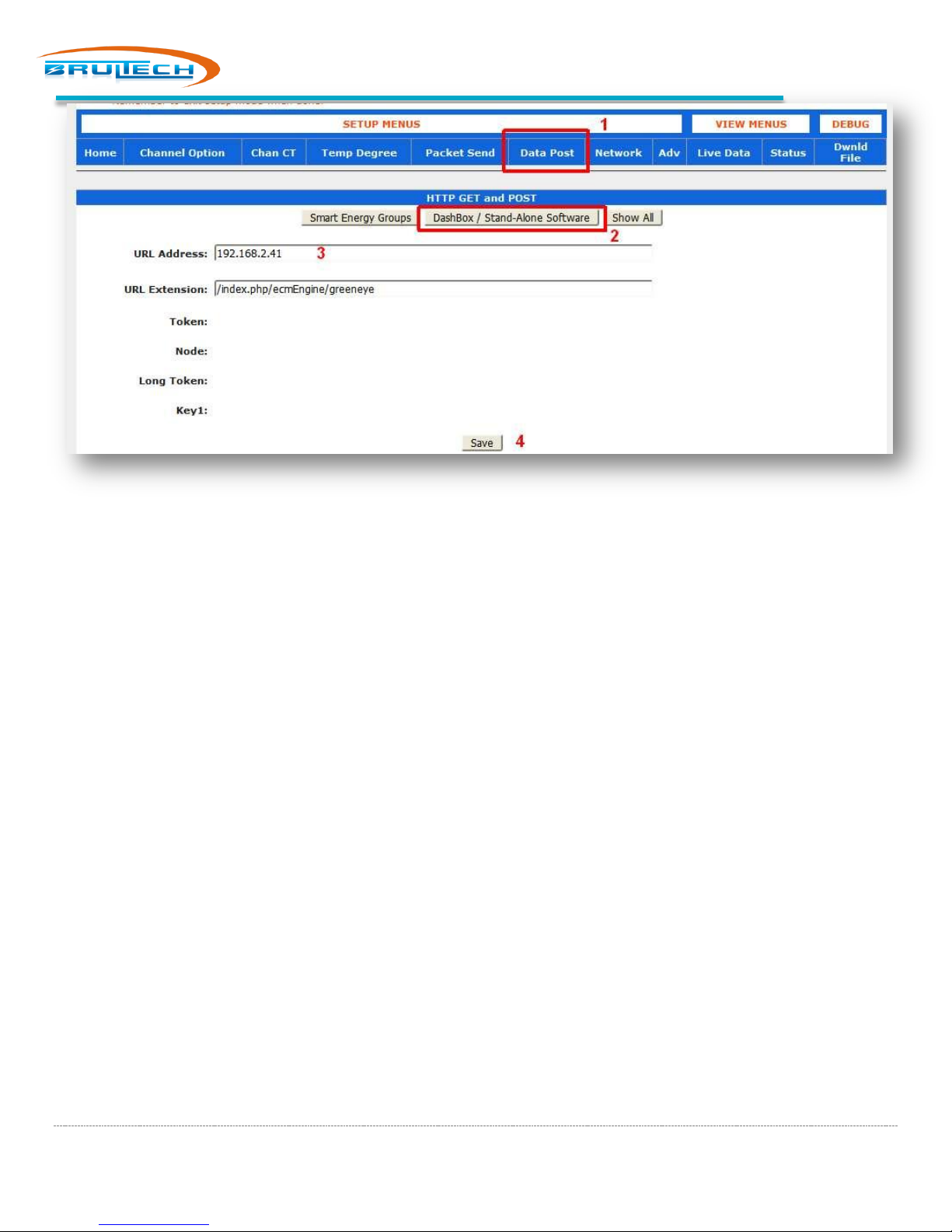
If the GEM sends data to the DashBox over the network (Option 2 Ethernet or WiFi GEM), then connect to the GEM
setup page and follow these steps (refer to screen shot on next page):
1. Select “Data Post” from the menu
2. Select “DashBox / Stand Alone Software” button
3. Under URL address, enter the DashBox IP address determined in the first step Ex: 192.168.0.45
4. Click “Save”
Page 25
Page 27
GEM Setup Procedure
PACKET SETUP
This section sets up the packet format being sent from the GEM to the DashBox. This differs based on whether
communicating using RS-232 (STS Cable) or via Network.
For RS-232 Serial Communication
1. Select the “Packet Send” menu
2. Set “Primary (Com1) Packet Format” to “4 Bin48-NET-Time”
3. Set the “Packet Send Interval” to 5 seconds
4. Set the “Secondary (Com2) Packet Format” to disable
5. Click “Save
For WiFi or Ethernet Communication
Model: GEM-WE / GEM-E
This procedure applies only for GEM devices communication with the DashBox over the network
1. Select the “Packet Send” menu
2. Set “Realtime Status” to “ON”
3. “Primary (Com1) Packet Format” to “3 HTTP GET”
4. “Packet Send Interval” to 8 seconds
5. “Secondary (Com2) Packet Format” to disable
6. Click “Save
Page 26
Page 28

GEM Setup Procedure
NETWORK SETUP (GEM WITH WIFI/ETHERNET)
If the GEM is connected to the DashBox using RS-232 (STS Cable), then skip this chapter.
The next step is to have the GEM send packets directly to the DashBox which are both connected to the same network.
The GEM needs to know the IP address and port number of the DashBox. The DashBox IP was determined earlier.
For GEM with WiFi/Ethernet option
Model: GEM-WE
Perform the next steps ONLY if the GEM uses a WiFi/Ethernet module!
1. Select the “Network” menu
2. Enter the DashBox IP address (determined earlier) in the “Host IP Address or URL Address:” box
3. Enter “80” for the port number (don’t include the quotation marks)
4. Click “Save”
GEM with Ethernet only option
Model: GEM-E
Perform the next steps ONLY if the GEM uses an Ethernet only module!
1. Open the GEM Network Utility program downloaded from the Brultech website
2. Select the “Ethernet Only” tab
3. Click “Search”. The GEM will be discovered and the fields populated
4. Enter the DashBox IP address (determined earlier) in the “Server IP” box. Ex: 192.168.0.48
5. Enter 80 for the “Remote Port” number
6. Click “Save”
Having completed these steps, the GEM is now sending data packets to the DashBox over the network.
Page 27
Page 29
Net Metering
NET METERING
SETTING CHANNEL POLARITY
By default, all GEM channels will display a positive value regardless of CT polarity. Grid connected solar or wind power
generation may generate more power than consumed. This results in a reversal of the electrical flow. The GEM can read
the direction of flow and show it as a positive amount when consuming and a negative amount when selling to the grid.
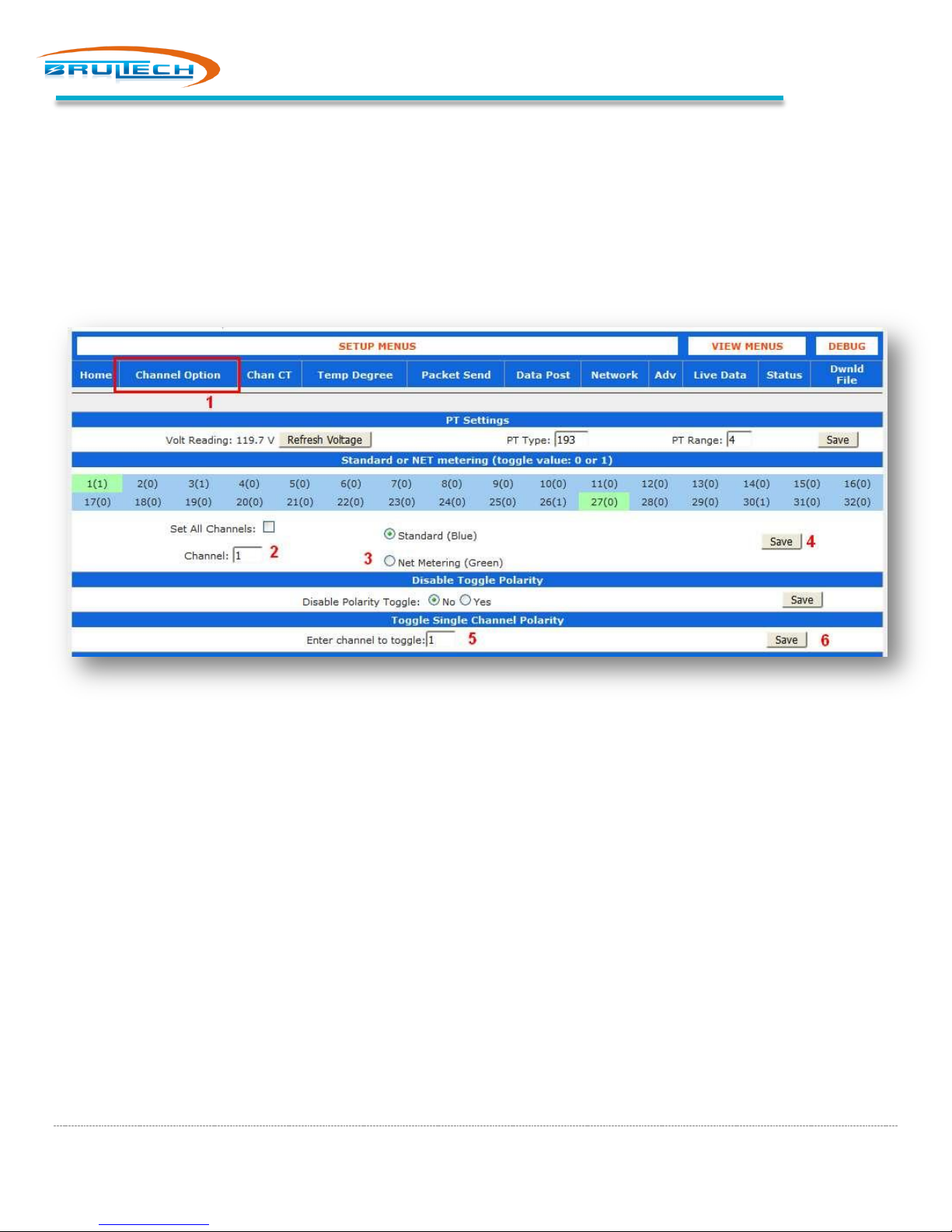
To allow the GEM to net meter, the “Main Panel” and “Solar” inverter channels need to be set to “Polarized”. The
screen shot below shows channels “1” and “27” set to “Net Metering” which will make the channels power polarized.
Procedure to change a channel to “Net Metering” (refer to screen shot above):
1. On the GEM Setup page, click the “Channel Option” menu
2. Enter the channel number for the “Main Panel” feed
3. Click the “Net Metering” radio button
4. Click “Save”
The area indicating the channel number will now change from blue to green. You can click “Live Data” to see if the main
panel channel is displaying the proper polarity. The watt value should be positive if consuming power and negative if
selling generated power. There is a 50/50 chance that the polarity is wrong. If so, then toggle the polarity(next).
TOGGLING THE POLARITY
In the “Toggle Single Channel Polarity” box:
1. Enter the channel number that is showing the wrong polarity
2. Click “Save”
Notice next to the channel number, the value in the brackets has now changed from “0” to “1” or from “1” to “zero”.
Once you have set your polarized channels, be aware that the PT (12Vac wall transformer) can affect this. See next
Page 28
Page 30
Net Metering
EFFECT OF THE PT ON POLARITY
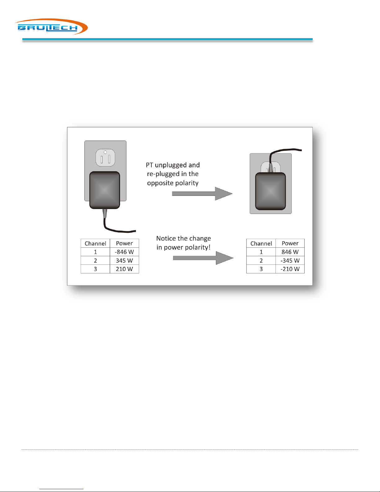
It is important to understand that the polarity of the PT (12Vac wall transformer) will change the polarity of any channel
that is “net metering” enabled (highlighted in green). For instance, if the wall transformer (PT) is unplugged turned 180
degrees and re-plugged such that the 120V receptacle blades are reversed, all net metering enabled channel polarities
will change. See Error! Reference source not found. below.
Page 29
Page 31
Temperature Sensors
TEMPERATURE SENSORS
1-WIRE BUS
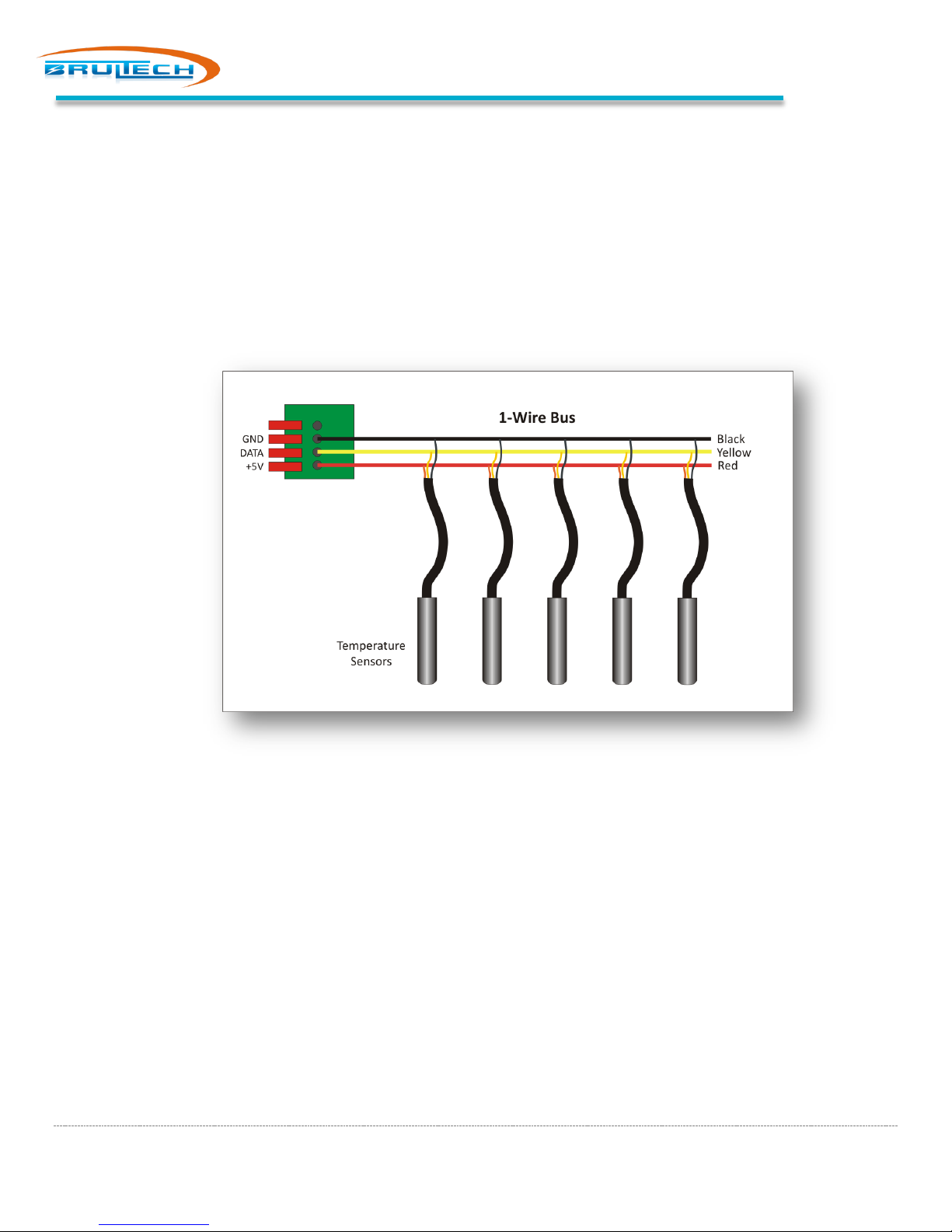
The GEM reads temperature using a “1-Wire” bus network. This system requires only three wires to address many
temperature sensors connected to a common line (see diagram below). The GEM design accommodates up to eight
sensors.
COMPATIBLE SENSORS
The GEM can accept the following two very common temperature sensors:
1. DS18B20
2. DS18S20
These are both very common and low cost. The DS18B20 is the most popular type.
Page 30
Page 32
Pulse Count
PULSE COUNT
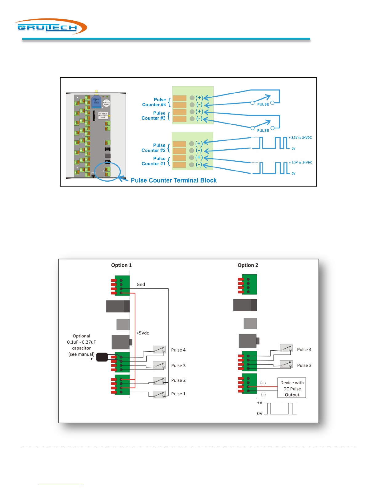
The GEM has four pulse count inputs. Pulse counter #1 and #2 are totally isolated from the GEM ground and circuit. If
using any of these inputs, a DC pulse signal between 3V and 24VDC is required.
Pulse counters #3 and #4 are “dry” contact type counters. These inputs require switch contacts not connected to any
power source, such as relay contacts or magnet switch contacts. Very low voltage from the circuit (5VDC) is used to
complete the circuit.
CONNECTION
Page 31
Page 33
Appendix A
APPENDIX A
IMPORTANT SECURITY INFO
Model: GEM-WE
This applies to “GEM-WE” WiFi/Ethernet models only!
The GEM will always have “Access Mode” activated. Once the GEM has been connected to your network, someone can
access your network through the Access Point. It is recommended to setup AP Security for the GEM’s access point (AP).
Connect to the GEM network setup page
1. Search for WiFi networks and connect to “GreenEye_xx” network
2. Open a browser and type “1.2.3.4” in the address bar. The sign-in page will appear
3. Type “admin” for both, the user name and password.
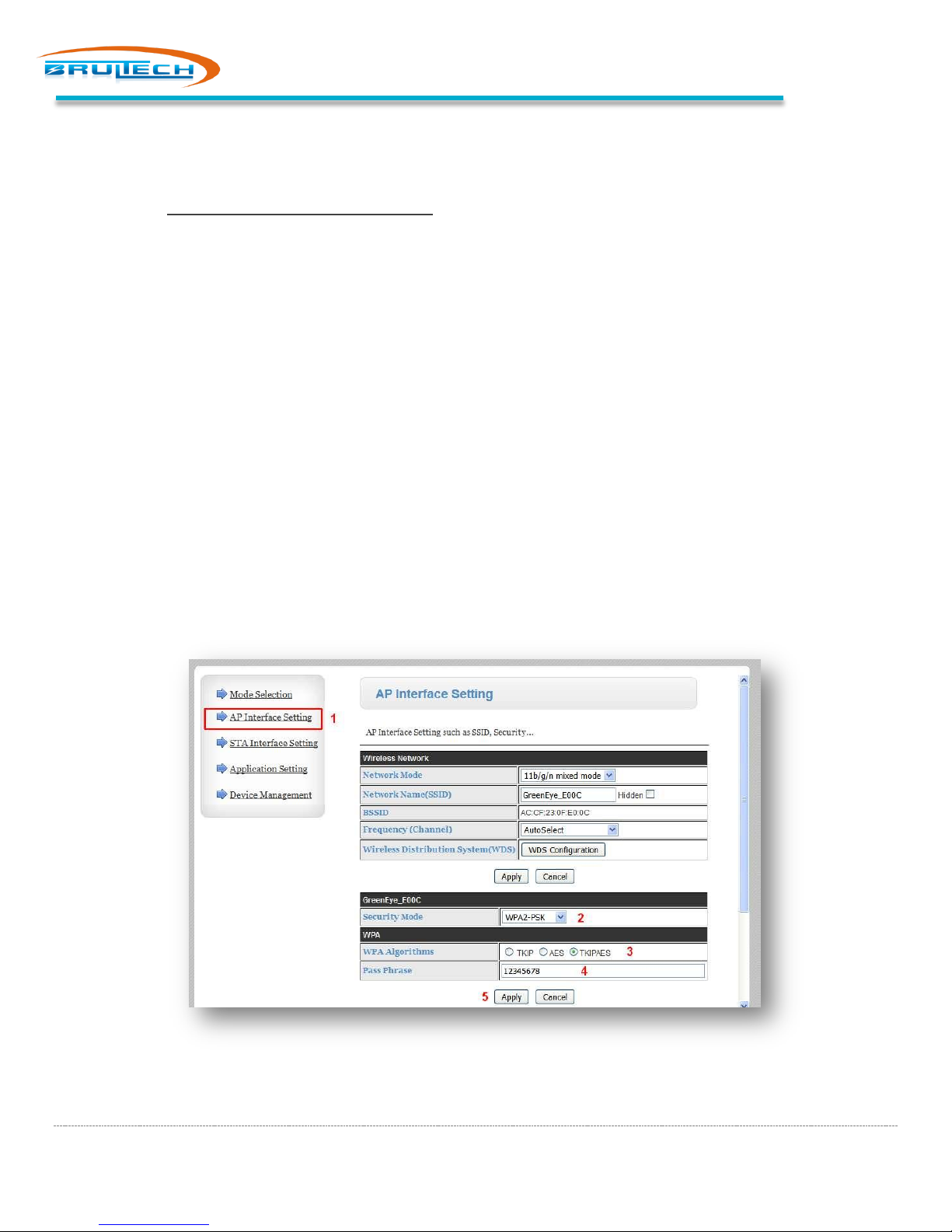
Steps to set WiFi Access Point security
1. Select “AP Interface Setting” from the menu
2. In the “Security Mode” drop down option, select your mode of choice; WPA2-PSK in this example
3. Select the “Algorithm”. “TKIP-AES” was selected in this example
4. Enter a “Pass Phrase”
5. Click apply
6. Select “Device Management” from the menu
7. Click “Restart”
It should be noted that the assigned security and password is reset when resetting module using the push button switch
next to the Ethernet jack on the GEM.
Page 32
Page 34

Appendix B
APPENDIX B
DASHBOX SWITCH FUNCTION
The DashBox has a small recessed switch in the back. This switch has various functions. Press and release the recessed
switch then notice the LED sequence.
1. Red briefly
2. Green (separator)
3. Orange briefly
4. Green (separator)
5. Dark briefly
6. Back to normal Green LED
Pressing the switch during the Red, Orange or Dark sequence will cause one of the following functions to take place:
Red = Reboot DashBox
Press the switch while the LED is Red. This will cause the LED to turn green and the DashBox will re-boot.
Orange = Reset Network Settings
Press the switch while the LED is Orange. This will cause the DashBox “Network Settings” to reset to its
default settings then automatically re-boot the DashBox so that the settings take effect.
Dark = Reset Dashboard Administration User/Pass.
Press the switch while the LED is Dark. This will cause the DashBox to reset the administration password to
the following:
Username: admin
Password: Brultech
Page 33
Page 35
Appendix B
Page 34
 Loading...