

Page 1
SCS
2
BLACK SHADOW
SERIES
3.1 DISPENSER
ALWAYS OBSERVE PRODUCT SAFETY AND
•
HANDLING INSTRUCTIONS.
ALWAYS DIRECT DISCHARGE AWAY FROM YOU or
•
other persons.
ALWAYS DISPENSE CLEANERS AND CHEMICALS
•
AS DIRECTED ON THE LABEL.
ALWAYS DISPENSE INTO APPROVED CONTAINERS
•
EXERCISE CAUTION: Turn off water supply when
•
maintaining or servicing your equipment.
KEEP EQUIPMENT CLEAN to maintain proper
•
operation.
WEAR PROTECTIVE CLOTHING AND EYE WEAR
•
when working in the vicinity of all chemicals, filling,
dispensing, emptying equipment or changing metering
tips.
ALWAYS RE-ASSEMBLE EQUIPMENT ACCORDING
•
TO INSTRUCTION PROCEDURES. Be sure all
components are firmly screwed or latched into
position.
NOTE: If the unit is used to fill a sink or the dispensing
•
hose can be placed into a sink, the unit must be
mounted so that the bottom of the cabinet is above
the overflow rim of the sink.
•
INSTALLATION MUST MEET LOCAL PLUMBING
CODES
NOTE: All installations must conform to local plumbing
•
codes and use approved backflow prevention devices.
A pressure indicating tee is to be installed with existing
faucets according to local plumbing codes in the state
of Wisconsin and any other state that requires the use
of a pressure indicating tee.
ASSE Standard 1055 Type B Approved Components
•
“Action Gap” backflow prevention devices is ASSE
Standard 1055 Type B approved.
SCS2 3.1 Dispenser Water Pressure Requirement
•
Water supply pressure should be in the 20-125 psi
range. Use cold water only
TURN OFF WATER TO DISPENSER WHEN NOT IN USE.
Tools Needed for Mounting SCS2 3.1 Dispenser
Hammer
•
Drill with 1/4”, 1/8”, 9/32”
•
and 5/32” Diameter Bits
Pliers
•
Medium Phillips
•
Screwdriver
•
Tape Measure
Straight Edge/Level
•
This package should contain
This instruction manual
•
Proportioner unit w/ 7ft. gas pump dispensing gun
•
(1) length of chemical inlet tubing, 7/32” I.D. x 15’ long
•
Metering tip kit
•
Screw & anchor Kit
•
(3) Cap adaptors
•
(2) SCS2 Product/Dispenser Sticker Sheets
•
Water proof, pressure sensitive Trouble Shooting Chart
•
Basic Operation
Warning: Use care when handling hazardous chemicals.
BRULIN RECOMMENDS INSTALLATION OF CUSTOM WALL CHART
AT DISPENSER SITE FOR DETAILED USE INSTRUCTIONS.
WEAR PPE – When handling concentrate, wear protective
1)
goggles & gloves
CAUTION: USE COLD WATER ONLY - DO NOT use hot water.
2)
SELECT PRODUCT - Turn selector valve arrow to desired
3)
product.
FILL with “Gas Pump” Dispensing Hose
4)
BUCKET OR AUTO SCRUBBER:
A.
Place dispensing hose into bucket or auto scrubber.
•
Squeeze trigger. The proper ratio of chemical and
•
water will flow into bucket or automatic scrubber.
Engage “lock-on” trigger feature if desired–depress
•
trigger and slide lock lever to right.
Release trigger when filled. (If using “lock-on” feature,
•
depress trigger to automatically release.)
SPRAY BOTTLES:
B.
Insert dispensing hose to bottom of bottle–minimizes
•
filling foam.
Squeeze trigger. The proper ratio of chemical and
•
water will flow into spray bottle.
Release trigger when ¾ filled.
•
Note: Approximately 4 oz. of diluted product remains
•
in hose. When switching products, gravity drain hose
– simply lower gun head to lowest point (drain/sink) for
3-4 seconds.
RINSE OPTION: • Select Water. • Place dispensing hose
B.
into container. • Squeeze trigger. • Engage lock-on
trigger feature if desired. Clear water will flow. • Release
handle when done.
WATER OFF! – Turn off water to dispenser when not in use.
5)
B R U L I N & C O . , I N C . • 8 0 0 - 7 7 6 - 7 1 4 9 • W W W.BRULIN.COM • I S O 9 0 0 1 : 2 0 0 0 C E R T I F I E D
Page 1 of 8
I884
192-117A 110905
Page 2
SCS2 Black Shadow Series – 3.1 Dispenser
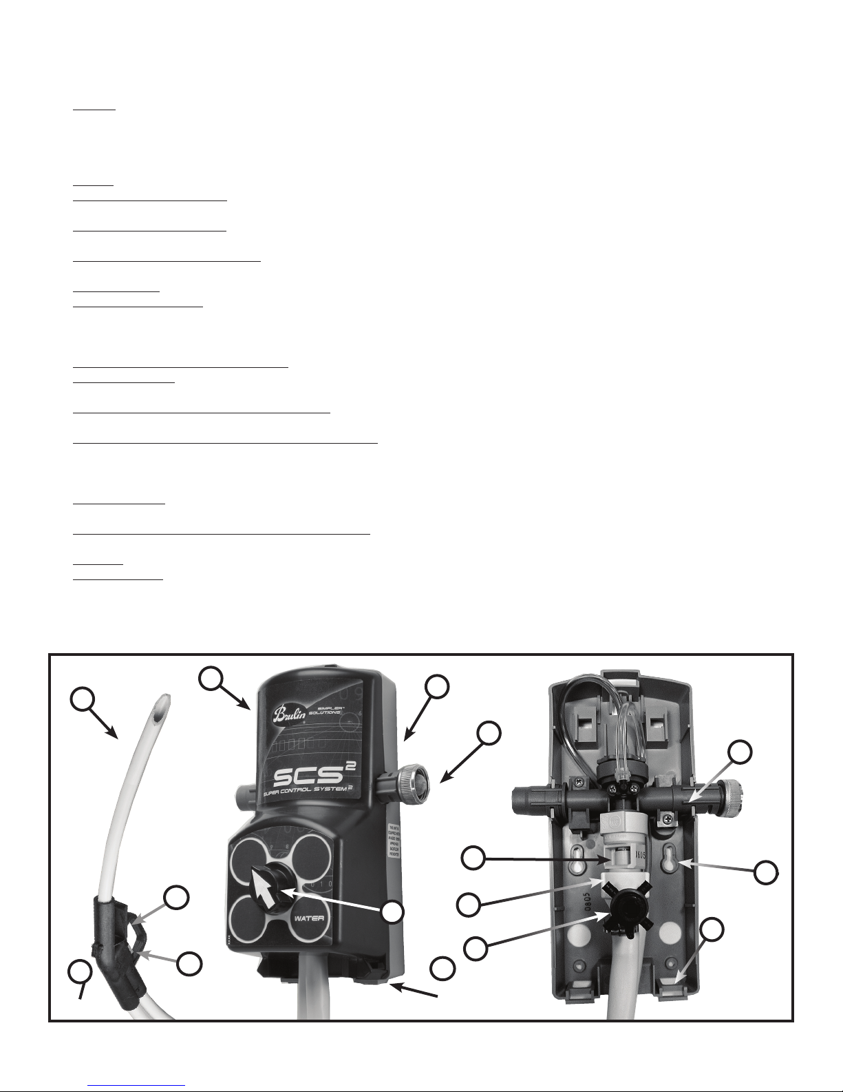
General Description
Cover: The cover is easily snapped into place for assembly and removed for serviceability. Insert the two lower
1.
tabs on the cover into the lower base pocket features. Rotate the upper cover towards the base making sure
the selector valve alignment pin is aligned with the corresponding hole in the cover. Continue to rotate the cover
towards the base until it snaps into place. Push down on upper cover snap-in lever feature and pull forward on
cover for removal.
Base: The base is used to mount the unit to the wall and to support the valve body mechanism.
2.
3.
Water Inlet Connection:
dispenser to the water supply line.
4.
Selector Control Knob:
chemical dilution.
5.
Backflow Prevention Device: The backflow prevention device prevents any chemical solution from flowing back
into the water supply. The “Action Gap” backflow prevention device is ASSE Standard 1055 Type B approved.
6.
Proportioner: The 4 GPM proportioner is white.
7.
Valve Subassembly: The valve assembly is a watertight valve utilizing high pressure “O-Rings”. The various
components are held together when the valve subassembly is slid into the retaining blades (forks) on the base
itself. (Note: The complete valve assembly must be subassembled then slid into the base or bases as “one”
component.)
Base Keyhole Mounting Bosses: Each unit has two keyhole bosses for mounting the unit to the wall.
8.
*Selector Body: One or more chemical supply and cap adaptor assemblies are connected to the selector body
9.
for drawing concentrated chemical out of one or more containers.
10.
Chemical Supply Hose Access Feature: The two bottom slot features in the base are used when the dispenser is
mounted to the wall.
Gas Pump Dispensing Hose/Handle Assembly: The Gas Pump Dispensing Hose is used to fill containers
11.
(buckets or trigger spray bottles) away from the unit by means of depressing the trigger. The outlet extends 11
inches past the base of the gun and is angled for minimal foaming. The container being filled must be positioned
lower than the dispenser.
12.
Hook Feature: The gas pump handle (gun) has a hook feature capable of sliding into the cover pocket feature for
storage.
Gas Pump Dispensing Hose Pocket Features: A pocket feature on either side of the cover is used to hang the
13.
gas pump dispensing gun onto the dispenser. The hose must be unhooked prior to removing the cover.
14.
Trigger: The trigger controls the flow of chemical/water solution through the outlet hose by depressing it.
15.
Trigger Lock:
to the right. Slowly release the trigger and it will stay in the “Lock” position. To “Unlock” the trigger, depress the
trigger to automatically release the locking mechanism.
*The selector body hose barb features are threaded to accept various size metering tips for controlling the desired chemical
induction flow rate (See section labeled “Install Metering Tips” on page 4 for detailed information.)
The trigger can be locked for continuous flow by depressing the trigger and sliding the lock lever
A female ¾ - 11 ½ hose swivel coupling with strainer washer is used to connect the
Selector knob allows the operator to choose either a desired chemical or amount of
1
11
14
12
Page 2 of 8
15
2
3
7
5
8
4
6
10
9
13
I884
192-117A 110905
Page 3
SEE STEP 2
3
3/4
4 1/2
WATER INLET
CONNECTION
(Note: All
dimensions are
in inches)
3 3/4
4 5/8
10
Table of Contents
Operation & Installation Requirements
•
•
Tools Needed for Mounting SCS
Package Contents
•
Basic Operation
•
General Description
•
•
Table of Contents
Installation
•
1.
Evaluate Wall Space
Lay Out & Drill Holes
2.
3.
Prepare Water Supply & Dispenser
4.
Mount Dispenser & Connect Water Supply
Concentrate Holder Installation
5.
Install Metering Tips
6.
7.
Tubing Installation
Connect Water Supply Hose
8.
Install Dispenser Cover
9.
Product Dilutions & Tip Chart
•
SCS2 Product Identification Stickers
•
2
Dispenser
Installation
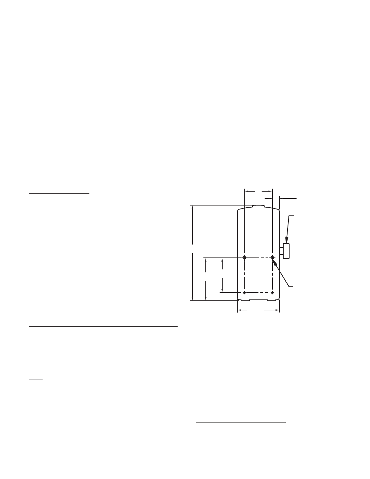
Evaluate wall space: Choose a suitable place within
1.
six feet (connector hose length) of water source.
Consider the location of the Concentrate Holder(s).
Wall space must be closely laid out to make sure there
is adequate room. Be sure to allow a minimum of 12
inches on both the left and right hand sides of the
dispenser. The added space will be used for hanging
the gas pump dispensing gun and for attaching the
water supply to the dispenser.
pg.1
pg.1
pg.1
pg.1
pg.2
pg.3
pg.3
pg.3
pg.3
pg.3
pg.3
pg.3
pg.4
pg.4
pg.4
pg.4
pg.4
pg.4
Maintaining and Servicing Dispenser
•
Gas pump hose assembly/disassembly
•
•
Checking backflow prevention device/
proportioner, metering tip(s), and/or foot
valve(s)
Parts List
•
Remote Fill Basic Unit
•
•
Remote Fill Valve Subassembly
Remote Fill Hose Assembly
•
•
“Action Gap”/Proportioner
Selector Assembly
•
•
Cover, labels, stickers, selector
•
Trouble Shooting Chart
pg.5
pg.5
pg.6
pg.6
pg.6
pg.6
pg.6
pg.7
pg.7
pg.7
pg.8
Lay out and drill holes in the wall: Carefully layout
2.
the proper mounting holes on the wall based on
the information in step 1 using a tape measure and
straight edge/level for hanging the dispenser on the
wall. (Drill all of the holes into the drywall using a
1/4” diameter bit for use with the included #10 x 1”
long screw and anchor set. If mounting the dispenser
to wood and you do not plan to use the included
anchors, drill 1/8” diameter holes.)
Get water supply line and dispenser ready so it can
3.
be mounted on the wall: Remove selector knobs
and cover. (Save all removed components in a safe
place for re-assembly.) A water supply line must be
plumbed up to the right hand side of the dispenser
using a male ¾ - 11 ½ N.H. hose coupling fitting.
Mount dispenser to wall and connect water supply
4.
line: Insert the anchors into drilled holes and hammer
them into the wall until they are flush with face of
wall. Assemble two #10 x 1” long screws with a
phillips screwdriver into the upper anchors so the
screw heads are sticking out of the wall approximately
½”. Carefully align the large section of the keyhole
slots in the dispenser base(s) over the screw heads.
Once positioned properly, push dispenser against the
wall over the screw heads and slide it down until the
keyhole slots are resting on the screws. Tighten the
screws against the keyhole bosses in each base. Now
install two #10 X 1” long screws in the lower anchors
Page 3 of 8
and tighten. Connect the water supply line to the
female swivel garden hose coupling on the dispenser
and tighten by hand. (Note: May need to tighten
hose coupling another ¼ turn with pliers but
OVERTIGHTEN
in the 20-125 psi range and water temperature must
not exceed 150°F. Slowly turn on the water supply
and check for any leaks. (Note: See section labeled
“Trouble Shooting” on page 8 if any continual leaks
are visible.) Mount water supply line to wall with
proper clamp(s) to avoid any damage to the dispenser.
Concentrate Holder Installation: The concentrate
5.
bottle top, (with the caps in place), should be below
the bottom of the dispenser. Position accordingly,
while also placing as near as possible to the dispenser
to insure proper flow.
concentrate above the height of the dispenser.
.) Water supply pressure should be
Caution: Avoid mounting
192-117A 110905
DO NOT
I884
Page 4
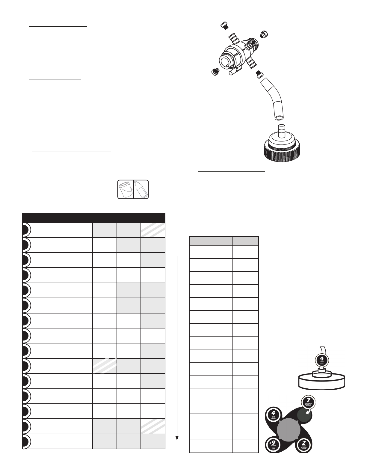
Install Metering Tips:
6.
A.
Consult the Dilution Tip Chart to determine the
correct tip color for the proper delivered dilution from
each concentrate.
B.
Screw tips into selector valves. Use charcoal gray tip
to plug any ports that are not connected to chemical.
HINT: Simultaneously apply product labels to the
C.
dispenser cover to match the metering tip locations.
Tubing Installation - To avoid mistakes plumb the
7.
tubing one product at a time. Hint: Label each
chemical tube to identify desired product to be
dispensed.
A.
Feed tubing, through holes in dispenser base, to
the desired port. Slide tubing over color tip and
on selector barb.
B.
Run tubing to the cap that fits the concentrate
bottle
Repeat until all of the concentrate bottles are plumbed
to the dispenser
8.
Connect Water Supply Hose to water inlet swivel.
(NOTE:
psi range. Use cold water only.
Water supply pressure should be in the 20-125
) Turn on water supply.
DILUTION TIP CHART
– BY PRODUCT
(Bucket/Scrubber OR Spray Bottle)
PRODUCT Regular Heavy Light
SPRING FRESH
0
Smoke & Odor Remover
QUAT CLEAN IV
s
0
Sanitizer
NEUTRAL
1
Cleaner
TERRAGREEN NEUTRAL
1
Cleaner SC
UNIQUAT NEUTRAL
D
1
Disinfectant 256
GREEN
2
Bathroom Cleaner
MAXIMA 256
3
Disinfectant Cleaner
BLUE
4
Glass Cleaner
TERRAGREEN BLUE
4
Glass Cleaner
RESTORER
5
Floor Cleaner
CLEAN N’ PREP
6
Deep Scrubber
FORMULA 815MX SC
7
Degreaser
TERRAGREEN
7
DEGREASER SC
#8 POWER NB
8
Degreaser
#9 POWER
9
Degreaser
*Not standard with dispenser tip package. Order separately.
N/A N/A
Lime
1:512
Turquoise
1:256
Light Blue
1:128
Pink
1:256
Blue
1:64
Pink
1:256
Black
1:32
Black
1:32
Capillary
Tip* 1:256
Pink
1:256
Yellow
1:50
Blue
1:50
N/A N/A
N/A N/A N/A
Page 4 of 8
4 Gal/Min
HBV Level
Brown
Brown
Purple
Purple
N/A N/A
Pink
1:128
Black
1:32
N/A N/A
N/A N/A
1:171
Grey
1:16
Grey
1:16
N/A N/A
1:128
1:20
1:20
Turquoise
1:256
Brown
1:128
Brown
1:128
None
1:32
N/A
N/A
Blue
1:50
N/A
N/A
None
1:18
Place this end
on concentrate
container.
Install Dispenser Cover. Insert lower tabs on the
9.
cover into the lower base. Rotate upper cover
towards the base and snap into place. Align & slide
the knob into the selector valve system until it snaps
in place. Be sure the Product ID stickers correctly
identify the product being dispensed.
DILUTION TIP CHART – BY
TIP SIZE
COLOR SIZE
Small
Large
BURGUNDY .004
LIME .010
TAN .0104
ORANGE .0109
TURQUOISE .0114
PINK .015
LIGHT BLUE .0167
BROWN .0175
RED .020
WHITE .021
GREEN .024
BLUE .0278
YELLOW .033
BLACK .0355
PURPLE .054
GREY .063
SCS2 Identification
Stickers:
For each product you will
•
use, place a product-number
sticker in a gray circle on
the selection dial, indicating
which SCS
be dispensed when the dial
points to that location.
Place the matching product-
•
number sticker around the
solution tubing just above
the fill cap. This identifies the
product to be connected.
•
Co ntinue this procedure
until all dial locations and
tubing connections have the
appropriate stickers.
2
product should
192-117A 110905
I884
Page 5
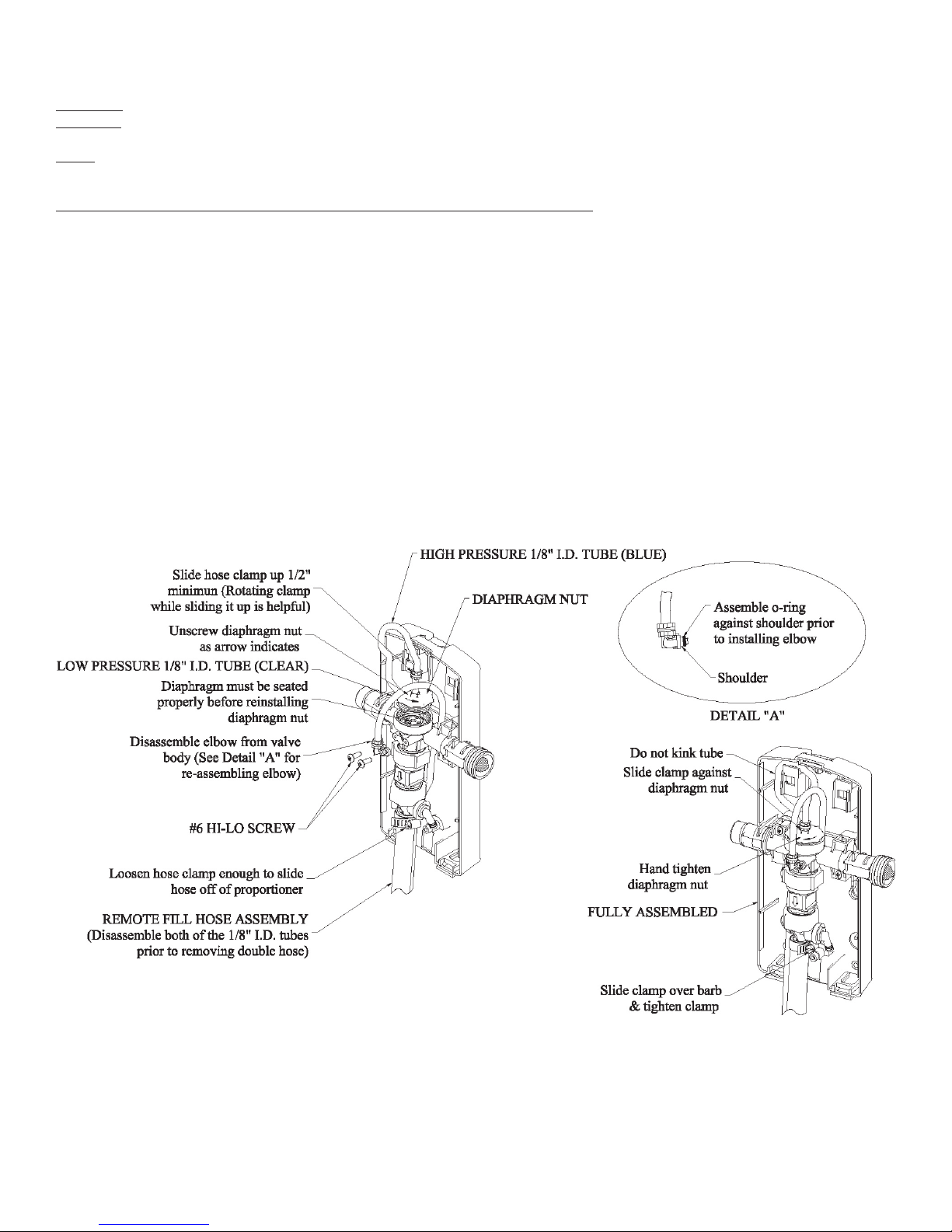
Maintaining and Servicing the SCS2 3.1 Dispenser
Caution: Turn off water supply before doing maintenance or servicing.
Warning: Use care when handling hazardous chemicals and use protective clothing/eyewear as recommended on
the product label. This includes handling of chemical supply and outlet tubes.
Note: Water supply pressure should be in the 20-125 psi range. Use cold water only.
Disassembling & reassembling the gas pump dispensing hose assembly:
Remove cover and selector knobs as necessary.
1.
2.
Removal of the double hose from the proportioner also involves the disconnection of both the clear and blue 1/8”
I.D. tubes. (Note: The 1/8” I.D. tubing is fairly stiff and the hose barbs can be damaged if not handled carefully.)
3.
Slide the upper hose clamp on the blue high pressure tubing up above the hose barb. (Note: It is helpful to use a
rotational motion when sliding the hose clamp up.)
4.
Unscrew the diaphragm nut in the direction shown on the sketch. (Note: The hose barb on the diaphragm nut will
need to rotate inside the 1/8” I.D. tubing to remove the nut.)
5.
Disassemble the elbow from the front of the valve body using a phillips screwdriver. (Note: The elbow is sealed to
the valve body via an O-ring. Be careful not to loose the O-ring.)
6.
Loosen the hose clamp holding the double hose to the proportioner. Remove the double hose off of the
proportioner using a steady pulling and rotational motion. Now you can get to the backflow prevention device/
proportioner.
7.
Repeat the same steps above in reverse order to reassemble the gas pump dispensing hose assembly. Pay spe
cial attention to push the double hose far enough on the proportioner so it lines up with the flat surface of the top
hose barb. Also see Detail “A” for proper installation of the O-ring onto the elbow before reassembling the elbow
to the valve body. (Note: Check to see that the diaphragm is properly seated then hand-tighten the diaphragm
nut.)
8.
Reassemble cover and selector knob with screw if so equipped. (Do not overtighten.)
-
Page 5 of 8
I884
192-117A 110905
Page 6
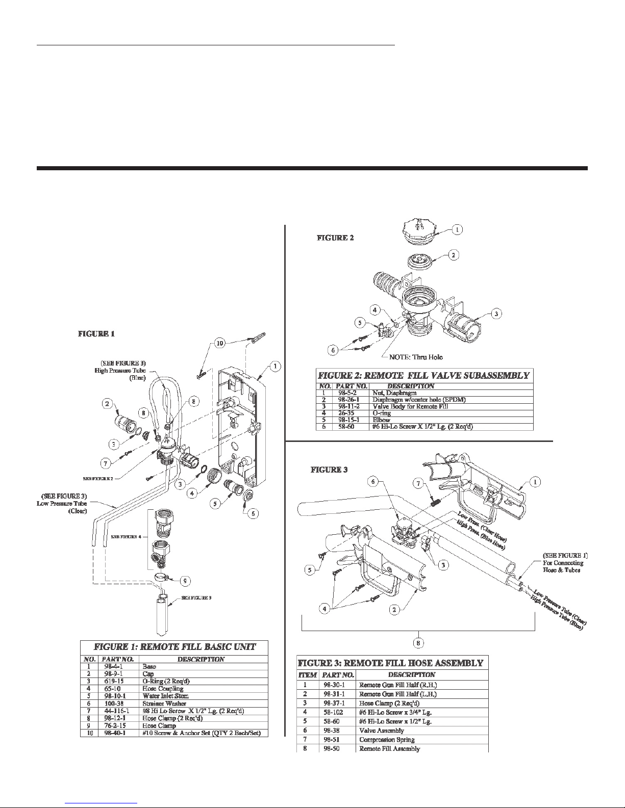
Checking backflow prevention device/proportioner and/or metering tip(s):
Remove cover and selector knob as necessary. Remove dispensing hoses and chemical supply tubes as neces
1.
sary. See section labeled “Disassembling & reassembling the gas pump dispensing hose assembly” for removing
the gas pump dispensing hose assembly.
Inspect metering tip(s) for clogging and for build up of dried chemical.
2.
3.
If clogged, remove the items and soak in hot water. Use cleaner to remove hard water deposits. Clean clogged
passageways with soft brush or other acceptable tools as necessary. (Note: Selector valve needs to be disas
sembled from proportioner before the proportioner can be removed).
Replace with clean or new parts as needed.
4.
Connect all outlet and chemical supply tubes.
5.
Reassemble cover and selector knob.
6.
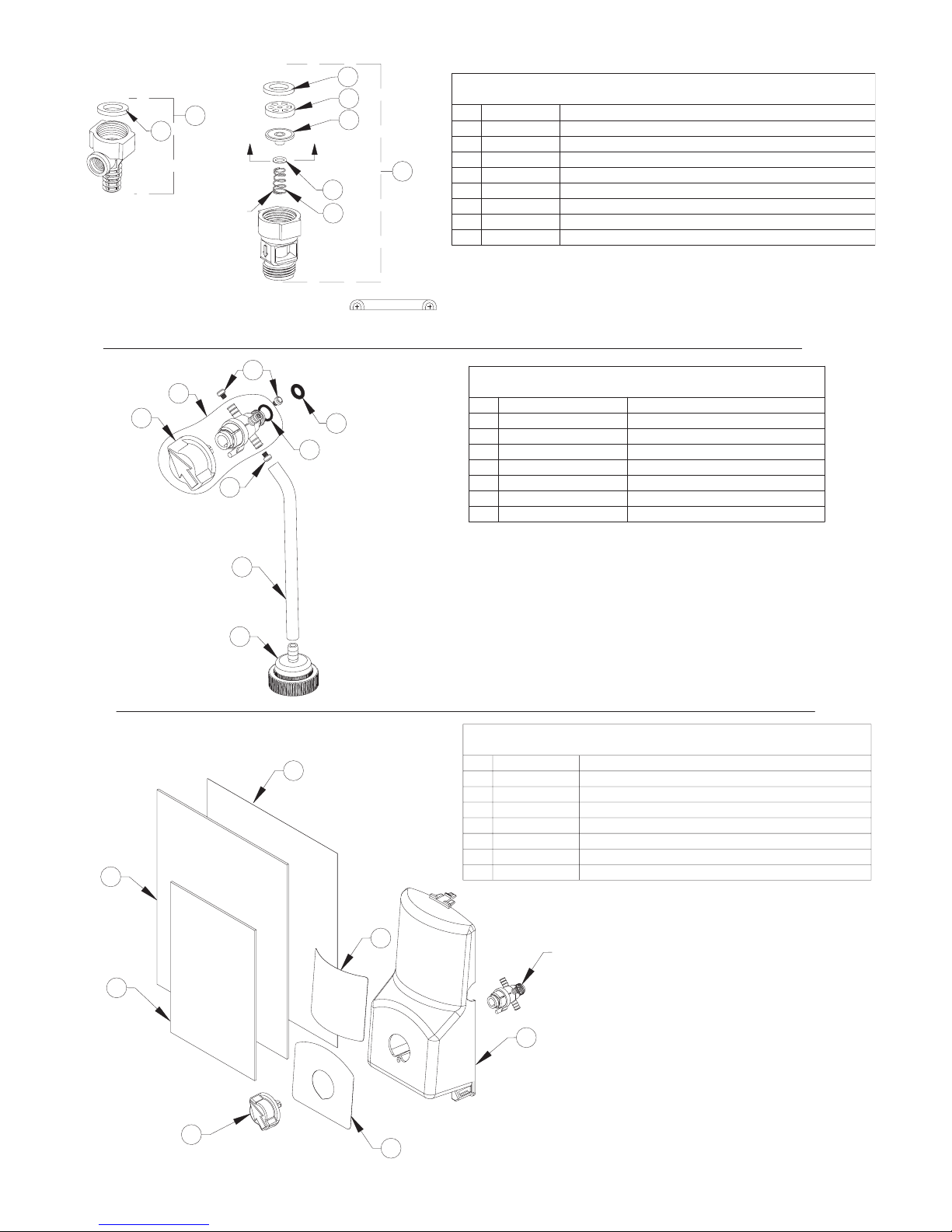
Parts List For SCS2 Black Shadow Series 3.1 Dispenser
(Gas Pump Dispensing Hose Assembly Application)
-
-
Page 6 of 8
I884
192-117A 110905
Page 7
A
A
1
2
NO.
DESCRIPTION
Rubber Washer
PART NO.
150-6
3
4
61-22GAP-3
Proportioner Assembly (4 GPM)
5
87-4-1
16-30
87-6-1
87-5-1
87-3-1
150-6-11
6
8
7
Rubber Washer
Action Gap Assembly
Diaphragm
Spring
Nozzle
Retainer
Tube, 15 Ft. Long
Selector Knob
O-ring
Metering Tip Kit
Selector Assembly
PART NO.NO.
63-78
66-40
98-8-2
100-12-29
100-15K-BRU1GAP
63-96-1EP-CK
6
7
3
5
4
2
1
63-111-2N
R&D Cap
O-ring
DESCRIPTION
6
L940
98-3-2BLK
7
192-111
3071/0904
PART NO.
63-111-2N
NO.
3
5
4
2
1
L939
3199/0605
Selector Knob
DESCRIPTION
Label, Cover
Cover
SCS Product Identification Sticker Sheet "A"
Pressure Sensitive Trouble Shooting Chart
SCS Product Identification Sticker Sheet "B"
Label, Selector
2
2
"Action Gap"
2
1
3
4
6
5
7
8
4 GPM Proportioner
FIGURE 4
Large end
of tapered
spring
* SECTION "A-A"
*
FIGURE 4: "ACTION GAP"/PROPORTIONER
5
4
2
6
7
FIGURE 5
FIGURE 6
7
6
4
1
2
3
FIGURE 5: "SELECTOR ASSEMBLY"
(SEE FIGURE 5)
3
FIGURE 6: COVER, LABELS, SHEETS, SELECTOR KNOB
5
1
3
Page 7 of 8
I884
192-117A 110905
Page 8

TROUBLE SHOOTING CHART
Trouble Probable Cause Remedy
Proportioner fails to draw
chemical properly.
Water valve is leaking. Enclosing tube nut is too
Threaded connections are
leaking water.
Proportioner continues to draw
chemical after water valve is
closed.
Can’t pull the Gas Pump
Dispensing Hose Assembly off
of the proportioner
Trigger on gas pump
dispensing Gun is very hard to
squeeze.
Excess concentrate draw Metering tip not in place1. Screw correct tip firmly in
Chemical will not hold prime Chemical cap is not
Gas pump quart fill – 1st fill when
switching to different product
dispenses previous product
Insufficient water supply
1. 20 PSI is the minimum
pressure.
1.
allowable pressure. Seek
plumber if necessary to
increase water pressure.
Proportioner metering tip
2. * Soak in hot water to clean
clogged with dried chemical.
3. Check cap and sipper tube3.
Bottle improperly connected
Clogged water inlet strainer4. Disconnect water inlet and
2.
interior passages.
4.
clean strainer
5. Replace tube5.
Air leak in chemical pickup
tube
1. Shut water supply off first.
loose.
1.
Hand-tighten the enclosing
hose nut. Do not overtighten
w/tool.
2. “O-ring” seals may be pushed
One or more of the valve Oring connections are out-ofposition. Clearly identify each
leak prior to disassembly.
2.
out of place or missing
when subassembling valve
together. Reassemble – refer
to installation guide.
The connection between the
1. Shut water supply off
dispenser and water supply
line is too loose or rubber
washer is missing.
1.
first. Carefully tighten the
female hose coupling on
the dispenser to the inlet
water supply line. Do not
overtighten.
2. Tighten loose connection(s)
Backflow prevention devices
and/or proportioners are too
loose.
Concentrated chemical is
1. Move the concentrated
positioned higher than the
proportioner.
1. Loosen clamp more.1.
Hose Clamp is not loose
2.
with tools if necessary. Do not
overtighten if using tools.
1.
chemical so it is lower than the
proportioner.
enough.
2. Remove 1/8” I.D. tubes.
Both 1/8” I.D. tubes must be
removed prior to removing the
double hose.
2.
See section labeled
“Disassembling &
reassembling the gas pump
hose assembly” in installation
guide.
1. Install the blue and clear
High pressure and low
pressure (blue and clear)
hoses are crossed.
1.
hoses. See installation guide
for instructions.
1.
place
2. Replace tip2.
Wrong metering tip in place
1. Ensure cap is straight & tight1.
connected properly
1. Gravity drain hose by lowering
Approximately 4 oz. of
previously dispensed product
remains in hose line.
1.
head to lowest point (sink/
drain) for 3-4 seconds.
* See section labeled “Checking backflow prevention device/proportioner, metering tip(s), and/or foot valve(s)” for more information.
Page 8 of 8
I884
192-117A 110905
 Loading...