


minispec
Temperature Unit TC3
●
User Manual
Version 003
Innovation with Integrity
AIC

Copyright © by Bruker Corporation
All rights reserved. No part of this publication may be reproduced, stored in a retrieval
system, or transmitted, in any form, or by any means without the prior consent of the
publisher. Product names used are trademarks or registered trademarks of their respective holders.
This manual was written by
Bruker BioSpin AIC
© October 26, 2015 Bruker Corporation
P/N: H148851
For further technical assistance for this product, please do not hesitate to contact your
nearest BRUKER dealer or contact us directly at:
Bruker Corporation
Am Silberstreifen
76287 Rheinstetten
Germany
Phone: + 49 721 5161 0
E-mail: minispec.SLS@bruker.com
Internet: www.bruker.com

Contents
Contents
1 About This Manual .............................................................................................................................5
1.1 Policy Statement ................................................................................................................. 5
1.2 Symbols and Conventions ..................................................................................................5
2 Introduction.........................................................................................................................................7
2.1 Overview .............................................................................................................................7
2.2 Features..............................................................................................................................8
2.3 Intended Use.......................................................................................................................8
3 Safety...................................................................................................................................................9
3.1 Safety Notices.....................................................................................................................9
3.1.1 Power Cord Set Requirements ...........................................................................................9
3.1.2 Power Cord Safety Maintenance ........................................................................................9
3.1.3 Mains Disconnect................................................................................................................9
3.1.4 Mechanical Hazards .........................................................................................................10
3.1.5 Thermal Hazards ..............................................................................................................11
3.1.6 Operating Environment ..................................................................................................... 11
3.1.7 Explanation of Caution and Warning Notices ...................................................................12
3.2 Electromagnetic Interference ............................................................................................ 13
3.3 Explanation of Regulatory Marks ...................................................................................... 14
4 Technical Data ..................................................................................................................................15
4.1 Environmental Characteristics ..........................................................................................15
4.2 Electrical Characteristics...................................................................................................15
4.3 Gas Connection ................................................................................................................16
4.4 Thermal Characteristics ....................................................................................................16
5 Transport, Packaging and Storage .................................................................................................19
6 Installation.........................................................................................................................................21
6.1 Site Selection .................................................................................................................... 21
6.2 Installing the Unit on the Base ..........................................................................................21
6.3 Connecting the Cables to the Sample Changer................................................................23
6.4 Connecting to a Power Source .........................................................................................24
6.5 Connecting the Nitrogen Supply .......................................................................................25
7 Operation...........................................................................................................................................27
7.1 Power-On..........................................................................................................................27
7.2 Power-Off..........................................................................................................................27
7.3 Controlling the Temperature .............................................................................................27
7.4 Understanding the LEDs...................................................................................................27
7.4.1 Power Indicator ................................................................................................................. 27
7.4.2 Zone Status Indicators ...................................................................................................... 27
8 Maintenance......................................................................................................................................29
8.1 Replacing the Fuse ........................................................................................................... 29
8.2 Replacing the Air Filter......................................................................................................30
H148851_3_003 3

Contents
8.3 Cleaning Instructions ........................................................................................................31
9 Dismantling and Disposal................................................................................................................33
9.1 Safety................................................................................................................................33
9.2 Dismantling .......................................................................................................................33
9.3 Disposal ............................................................................................................................34
10 Contact ..............................................................................................................................................35
List of Figures...................................................................................................................................37
List of Tables ....................................................................................................................................39
Index ..................................................................................................................................................41
4 H148851_3_003

1 About This Manual
Before starting any work, personnel must read the manual thoroughly and understand
its contents. Compliance with all specified safety and operating instructions, as well as local
work safety regulations, are vital to ensure safe operation.
The figures shown in this manual are designed to be general and informative and may not
represent the specific Bruker model, component or software/firmware version you are
working with. Options and accessories may or may not be illustrated in each figure.
1.1 Policy Statement
It is the policy of Bruker to improve products as new techniques and components become
available. Bruker reserves the right to change specifications at any time.
Every effort has been made to avoid errors in text and figure presentation in this publication.
In order to produce useful and appropriate documentation, we welcome your comments on
this publication. Support engineers are advised to regularly check with Bruker for updated
information.
Bruker is committed to providing customers with inventive, high quality products and services
that are environmentally sound.
About This Manual
1.2 Symbols and Conventions
Safety instructions in this manual are marked with symbols. The safety instructions are
introduced using indicative words which express the extent of the hazard.
In order to avoid accidents, personal injury or damage to property, always observe safety
instructions and proceed with care.
DANGER indicates a hazardous situation which, if not avoided, will result in
death or serious injury.
This is the consequence of not following the warning.
1. This is the safety condition.
u This is the safety instruction.
WARNING indicates a hazardous situation, which, if not avoided, could result
in death or serious injury.
This is the consequence of not following the warning.
1. This is the safety condition.
u This is the safety instruction.
DANGER
WARNING
H148851_3_003
5

About This Manual
CAUTION indicates a hazardous situation, which, if not avoided, may result in
minor or moderate injury or severe material or property damage.
This is the consequence of not following the warning.
1. This is the safety condition.
u This is the safety instruction.
NOTICE indicates a property damage message.
This is the consequence of not following the notice.
1. This is a safety condition.
u This is a safety instruction.
CAUTION
NOTICE
SAFETY INSTRUCTIONS
SAFETY INSTRUCTIONS are used for control flow and shutdowns in the event
of an error or emergency.
This is the consequence of not following the safety instructions.
1. This is a safety condition.
u This is a safety instruction.
This symbol highlights useful tips and recommendations as well as
information designed to ensure efficient and smooth operation.
6 H148851_3_003

2 Introduction
2.1 Overview
The TC3 temperature unit, also called a dry bath, allows you to control the temperature of
samples in an ASX-7000-series sample changer. It heats or chills the samples under the
control of a host computer.
Introduction
Figure2.1: The TC3 Unit.
The temperature unit comes in three versions:
• 10 mm SFC version: The unit holds vials in three temperature-controlled zones. Each
zone holds 60 vials, with a maximum temperature of 100° C.
• 10 mm polymers version: The unit holds vials in one temperature-controlled zone. Each
zone holds 60 vials, with a maximum temperature of 110° C.
• 26 mm version: The unit holds vials in two temperature-controlled zones. Each zone
holds 24 vials, with a maximum temperature of 80° C.
A power cord and appropriate data cables are also provided.
H148851_3_003
7

Introduction
2.2 Features
Temperature Range
Three zones hold samples at 0° C to +100° C.
Sample Changer Compatibility
Use only with an ASX-7600 pick-and-place NMR sample changer.
Chemical Compatibility
Exposed surfaces are made of corrosion‑resistant stainless steel alloys or anodized
aluminum.
2.3 Intended Use
This equipment is designed for use in analytical laboratories performing chemical analysis of
samples.
8 H148851_3_003

3 Safety
Review this product and related documentation to familiarize with safety markings and
instructions before you operate the instrument.
3.1 Safety Notices
Injury Hazard
If the device is used in a manner not specified by the manufacturer, the protection provided
by the device may be impaired.
Safety
CAUTION
Repair or service that is not covered in this manual should only be performed by qualified
personnel.
3.1.1 Power Cord Set Requirements
The power cord set supplied with the device meets the requirements of the country where the
device was purchased. Power is supplied to the device through the included 24V power
supply.
3.1.2 Power Cord Safety Maintenance
The operator should check the condition of the power/signal supply cord. The device should
not be operated if the mains inlet is cracked or broken. Any obvious damage to the case
(from a drop or fall) should be checked by service personnel for loose or damaged parts.
Refer to the individual part lists, or contact Bruker, for approved replacement parts.
3.1.3 Mains Disconnect
The power switch on the rear panel is not the mains disconnect. Power mains disconnect is
accomplished by unplugging the power cord from the power supply or from the wall outlet.
Ensure the power cord is easily accessible and removable, in the event of an emergency
which requires immediate disconnection.
H148851_3_003
9

Safety
Fire and Shock Hazard
Incorrect installation or use of the power supply may result in a fire or shock hazard.
u Use only the provided power supply.
u The power supply must be plugged into an outlet which has a protective ground
connection.
u Ensure that the power cord is disconnected before removing any covers.
3.1.4 Mechanical Hazards
WARNING
Figure3.1: Bottom View with Filter Drawer Removed
WARNING
Laceration Hazard
If the unit power is left on, the spinning fan blade just above the filter may cause injury.
u Ensure the AC power is off before removing the filter.
WARNING
Lifting Hazard
Lifting without assistance may cause injury.
u Two people are required to lift the device.
u Lifting should be done with a person situated on either side of the device.
10 H148851_3_003
3.1.5 Thermal Hazards
Burn Hazard
Incorrect handling of vials or inserting fingers into any holes in the device may result in burn
injuries.
u Do not handle vials from heated zones until they have been given time to cool.
u Do not attempt to insert fingers into any holes in the device.
3.1.6 Operating Environment
Shock Hazard from Rain or Humidity
Device exposure to rain or humidity could result in a risk of fie or electrical shock.
u Do not expose the device to rain or humidity.
u Do not open the cabinet, all maintenance is to be performed by an authorized service
provider.
Safety
WARNING
WARNING
Protection provided by the device may be impaired if the device is used in a manner not
specified by the manufacturer.
WARNING
Shock Hazard from Liquids
Liquid coming in contact with electrical components may result in a serious injury through
shock.
u Do not allow any liquid to enter the device cabinet other than as intended through the
specified tubing, or come into contact with any electrical components.
u The device must be thoroughly dry before you reconnect power, or turn the device on.
WARNING
Explosion Hazard
Explosive atmospheres caused by flammable gases, mists or vapors or by combustible
dusts could result in an explosion.
u Prevent the release of dangerous substances, which can create explosive atmospheres.
u Prevent sources of ignition.
u Do not operate the device in an explosive atmosphere.
H148851_3_003
11

Safety
WARNING
Chemical Hazards
Incorrect use of chemicals used in and near the device may result in injury or property
damage.
u Learn about the chemicals which will be used in and near the device, and observe the
necessary precautions.
u Always use appropriate personal protective equipment, including protective eyewear.
3.1.7 Explanation of Caution and Warning Notices
Warning symbol marked on device.
• This symbol means “Attention! Refer to the
manual.
Crush Hazard / Pinch Point.
• Keep hands clear of moving parts. X, Y, Z axis
movement may crush hand.
Puncture Hazard – Moving parts can cause severe
injury.
• Do not put hand under the gripper assembly!
12 H148851_3_003

Lifting Hazard – Single person lift could cause injury.
• Use assistance when moving or lifting.
Table3.1: Explanation of Caution and Warning Notices
3.2 Electromagnetic Interference
Safety
FEDERAL COMMUNICATIONS COMMISSION (FCC) NOTICE
This equipment has been tested and found to comply with the limits for a Class A digital
device, pursuant to Part 15 of the FCC Rules. These limits are designed to provide
reasonable protection against harmful interference in a commercial installation.
This equipment generates, uses, and can radiate radio frequency energy and, if not installed
and used in accordance with the instructions, may cause harmful interference to radio
communications. Operation of this equipment in a residential environment is likely to cause
harmful interference, in which case the user will be required to correct the interference at his
expense.
MODIFICATIONS
The FCC requires the user to be notified that any changes or modifications made to this
device that are not expressly approved by the manufacturer may void the user's authority to
operate the equipment.
CABLES
Connections to this device must be made with shielded cables with metallic RFI/EMI
connector hoods to maintain compliance with FCC Rules and Regulations.
CANADIAN NOTICE
This digital apparatus does not exceed the Class A limits for radio noise emissions from
digital apparatus as set out in the interference-causing equipment standard entitled "Digital
Apparatus" ICES-001 of the Department of Communications.
AVIS CANADIEN
Cet appareil numérique respecte les limites de bruits radioélectriques applicables aux
appareils numériques de Classe A prescrites dans la norme sur le matériel brouilleur:
"Appareils Numériques," NMB-001 édictée par le ministre des Communications.
H148851_3_003
13

Safety
3.3 Explanation of Regulatory Marks
The CE mark is a registered trademark of the European Community. This CE mark
shows that the product complies with all the relevant European Legal Directives.
14 H148851_3_003
4 Technical Data
4.1 Environmental Characteristics
These environmental characteristics indicate the conditions for safe operation. Instrument
performance may depend on the ambient conditions.
Operating Temperature +5° C to +40° C (+41° F to +104° F)
Technical Data
Non-Operating
Temperature
Operating Altitude Up to 2,000 m (6,562 ft.)
Relative Humidity 0% to 80% non-condensing for temperatures up to 31° C,
Non-Operating Relative
Humidity
Pollution Degree Pollution degree 2.
Table4.1: Environmental Characteristics
For indoor use only.
Avoid sudden, extreme temperature changes which could cause condensation on circuit
boards in the device.
+0° C to +55° C (+32° to +131° F)
decreasing linearly to 50% at 40° C.
0% to 95% non-condensing.
Normally no pollution or only dry, non-conductive pollution
occurs. The pollution has no influence. Occasionally,
however, a temporary conductivity caused by condensation
may be expected.
4.2 Electrical Characteristics
Power Input:
RS232 RS-232 serial connection to the sample
RS485 TIA/EIA-485 (use only for connection to
Table4.2: Electrical Characteristics
H148851_3_003
AC voltage, frequency, and current
100-240 V ~, 50-60 Hz, 5 A maximum
Installation category: CAT II (line voltage in
appliance and to wall outlet)
changer (max ±12VDC, 8 mA)
another temperature unit, max ±8VDC, 200
µA)
15

Technical Data
4.3 Gas Connection
One fitting is provided for nitrogen purge gas. The nitrogen source must be regulated to a
pressure of no more than 35 kPa (5 psi, 0.35 bar). A typical gas flow of 0.5 liter/minute shall
apply.
4.4 Thermal Characteristics
Figure4.1: Thermal Characteristics of a 3-Zone 10 mm SFC Version
Zone Default Temperature Temperature Range
3 0° C 0° C to +66° C
2 65° C Ambient +5° C to +66° C
1 100° C Ambient +5° C to +100° C
16 H148851_3_003

Figure4.2: Thermal Characteristics of a 1-Zone 10 mm Polymers Version
Technical Data
Zone Default Range
1 Ambient +5° C to +110° C
Figure4.3: Thermal Characteristics of a 2-Zone 26 mm Version
H148851_3_003
Zone Temperature Range
2 Ambient +5° C to +80° C
1 Ambient + 5° C to +80° C
17

Technical Data
18 H148851_3_003
Transport, Packaging and Storage
5 Transport, Packaging and
Storage
WARNING
Lifting Hazard
Lifting without assistance may cause injury.
u Two people are required to lift the device.
u Lifting should be done with a person situated on either side of the device.
Inspect external packaging upon receipt for signs of shipping damage. Inspect all items
during unpacking and notify the carrier immediately of any concealed damage. Check for
kinked tubing.
If the system is shipped or removed from storage during cold weather, allow the packaged
equipment to equilibrate to room temperature before opening and exposing to warm, humid
air. It is usually sufficient to provide four to eight hours for this purpose.
CAUTION
Equipment Damage from Condensation
If condensation forms on or inside the unit, allow it to dry thoroughly before connecting it to a
power source and operating it. Failure to do so may cause equipment damage.
Remove the packing checklist from the shipping container, and check off items against it.
Leave accessories in the packing until you are ready to install them.
Note: Keep the factory packaging for use in case the product ever needs to be returned or
shipped to another location.
H148851_3_003
19

Transport, Packaging and Storage
20 H148851_3_003

6 Installation
6.1 Site Selection
Follow the guidelines in the sample changer Operator's Manual to choose a location for the
system. Keep in mind that:
• You will need to be able to access the back of the system to install cables and tubing.
• Place the sample changer within 1.2 meters of a power outlet.
• Allow at least 5 cm behind the power supply for cable egress, ventilation, and access to
the power switches. Always position the equipment so that it is easy to disconnect the
power cord.
6.2 Installing the Unit on the Base
WARNING
Installation
Lifting Hazard
Lifting without assistance may cause injury.
u Two people are required to lift the device.
u Lifting should be done with a person situated on either side of the device.
WARNING
Pinch/Puncture Hazard
Ensure the AC power is off before proceeding with installation. If the power is left on, motors
may move unexpectedly and cause injury.
H148851_3_003
21
Installation
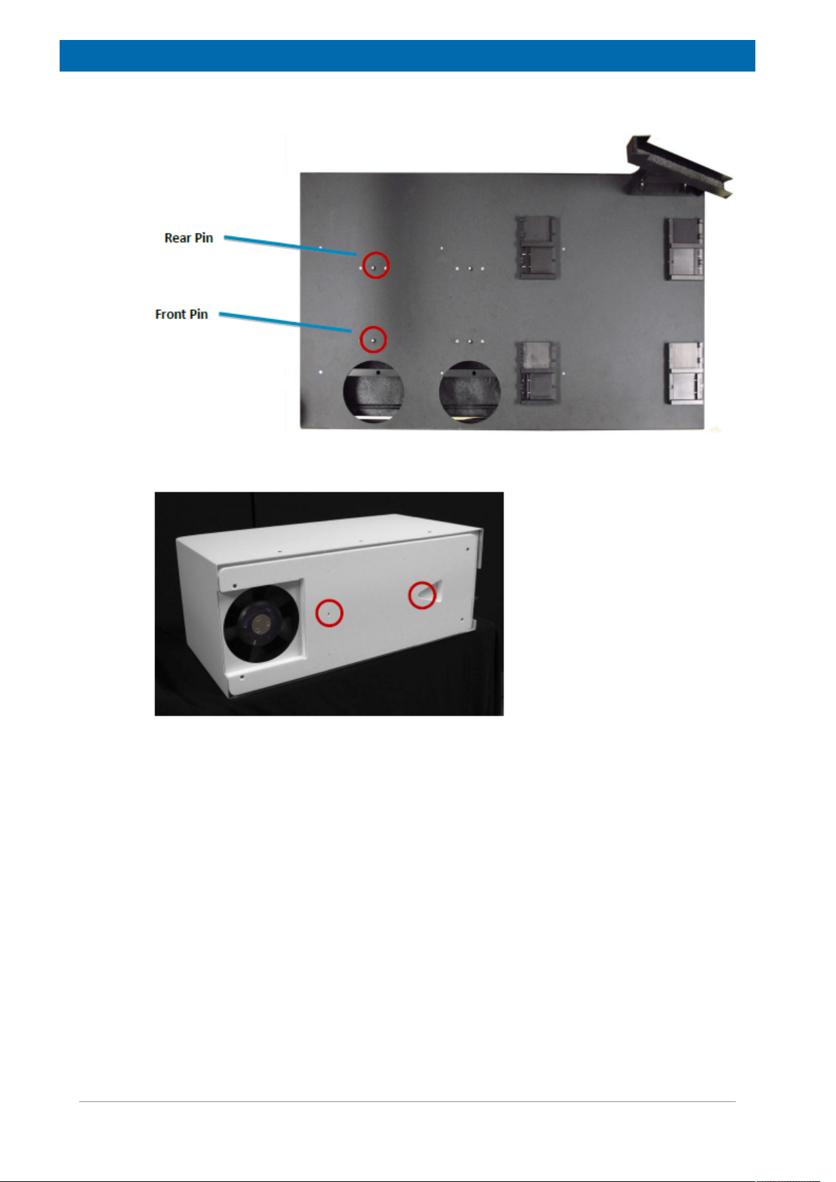
The temperature unit is positioned by means of two spring-loaded pins:
Figure6.1: Base of the Sample Changer
Figure6.2: Bottom of the Temperature Unit
• If using a version which is equipped with an air filter, remove the filter drawer from the
front of the temperature unit. This provides an additional lifting point.
With the help of an assistant, place each temperature unit on the base of the sample
changer slightly toward the front edge of the base.
• Keep the bottom of the temperature unit parallel to the base, so that the corners don't
gouge the finish on the base.
• Slide the temperature unit back until the pins engage the holes. You should hear or feel a
click.
22 H148851_3_003
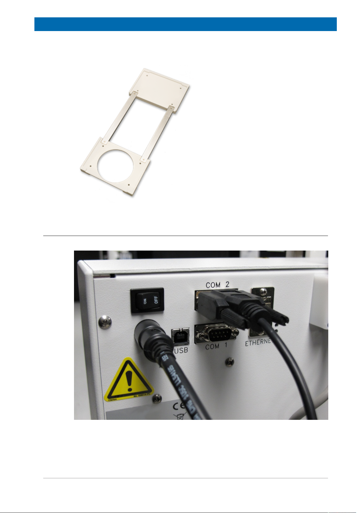
Installation
Note: You can mount the temperature unit on a bench top or table using the optional table
adapter:
Figure6.3: Optional Table Adapter
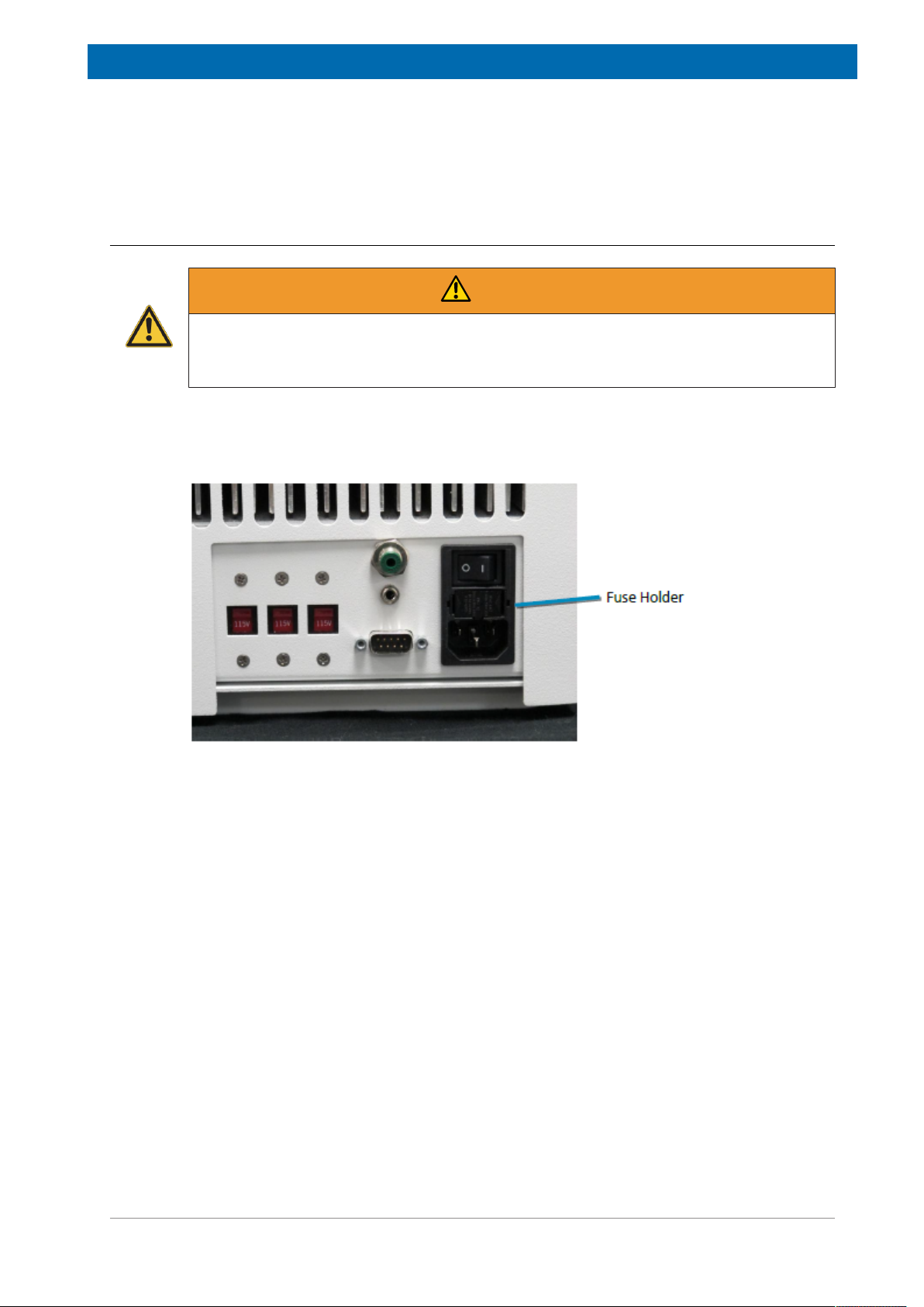
6.3 Connecting the Cables to the Sample Changer
• Connect the 9-pin serial cable to the COM 2 port on the sample changer.
Figure6.4: Serial Cable Connected to the Back of the Sample Changer.
• Connect the other end of the serial cable to the RS232 port on the unit.
H148851_3_003
23

Installation
Figure6.5: Serial Connector on the Unit.
• Connect the sample changer to the host computer as described in the sample changer
Operator's Manual.
• If using a TC3 and TC6 temperature unit together, connect the supplied RS-485 serial
cable between the two temperature units.
6.4 Connecting to a Power Source
• Turn the power switches on the sample changer and power supply OFF.
• Check the plug on the power cord to verify that it is of the correct type for your country.
Contact the manufacturer if you need a different power cord.
• Set the voltage selection switches to the correct voltage for your country (115VAC or
230VAC).
WARNING
Fire and Shock Hazard
Incorrect installation or use of the power supply may result in a fire or shock hazard.
u Use only the provided power supply.
u The power supply must be plugged into an outlet which has a protective ground
connection.
u Ensure that the power cord is disconnected before removing any covers.
• Locate the proper fuse for your voltage, then install the fuse in the fuse holder.
• Push the fuse holder in until it clicks into place.
• Plug the power cord into the back of the unit.
24 H148851_3_003

Installation
Figure6.6: Power Connections for the Unit
• Plug the power cord into a power outlet.
It is important to use the appropriate power cord for your country. See Power Cord Set
Requirements [}9].
6.5 Connecting the Nitrogen Supply
A source of low-pressure nitrogen may be connected for purging the unit. The nitrogen
displaces air within the unit to prevent condensation.
Use a regulator. The nitrogen source must supply a pressure of no more than 35 kPa (5 psi,
0.35 bar). A typical gas flow of 0.5 liter/minute shall apply.
Use as little nitrogen as is needed to prevent condensation.
If the pressure exceeds 35 kPa, the excess nitrogen will be vented and you will hear a hissing
sound.
Figure6.7: Nitrogen Connection for the Unit
H148851_3_003
25

Installation
26 H148851_3_003

7 Operation
7.1 Power-On
To turn the system on, first turn the temperature unit switch ON, then the sample changer.
7.2 Power-Off
To turn the system off, first turn the sample changer power switch OFF, then the temperature
unit.
In case of emergency, or before performing maintenance, remove the power cord from the
back of the temperature unit and from the sample changer.
7.3 Controlling the Temperature
The host computer sends commands to the sample changer, which then passes the
commands through to the power supply.
Operation
7.4 Understanding the LEDs
There are two kinds of LEDs on the temperature unit:
• A power indicator.
• Status indicators for each temperature control zone.
Figure7.1: LEDs (for 10 mm SFC version with 3 zones).
7.4.1 Power Indicator
Green: Lighted green when power is connected.
7.4.2 Zone Status Indicators
Red: Flashing indicates it is heating and in transition to a set point, solid indicates it is heating
and at a set point.
Blue: Flashing indicates it is chilling and in transition to a set point, solid indicates it is chilling
and at a set point.
H148851_3_003
27

Operation
28 H148851_3_003
8 Maintenance
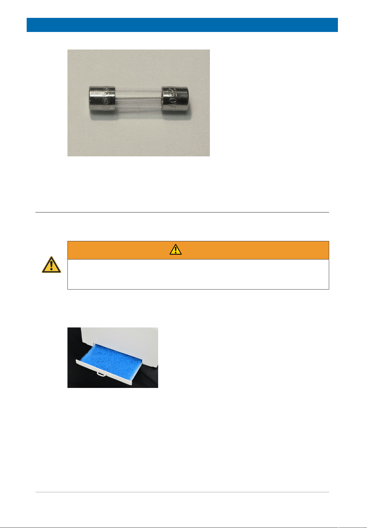
8.1 Replacing the Fuse
Fire and Shock Hazard
Using an incorrect fuse may cause fire or personal injury. .
u Replace the fuses only with a 10A 250V slow-blow 5x20 mm fuse (T10AL250V).
Two fuses are located in the power supply, just above the power cord connector.
Maintenance
WARNING
Figure8.1: Fuse Holder for the TC3
• Disconnect the power cord.
• Inspect all of the equipment which is plugged into the power supply for moisture or other
conditions which might pose a hazard and cause the new fuse to blow.
• Using your fingernails or a small, flat-blade screwdriver, squeeze the ends of the fuse
holder.
• Pull the fuse holder out.
• Replace the blown fuse with a new one of the same size, type, and rating.
H148851_3_003
29
Maintenance
Figure8.2: Fuse
• Press the fuse holder back in until it clicks into place.
• Plug the power cord back in.
8.2 Replacing the Air Filter
The 3-zone 10 mm SFC version of the TC3 includes a user-replaceable air filter. Contact
Bruker for information on replacement filters.
WARNING
Laceration Hazard
If the unit power is left on, the spinning fan blade just above the filter may cause injury.
u Ensure the AC power is off before removing the filter.
• Turn the power switch off.
• Pull the filter drawer open.
Figure8.3: Opening the Filter Drawer
• Remove the old filter. If necessary, use your fingers to pull it out of the opening.
30 H148851_3_003
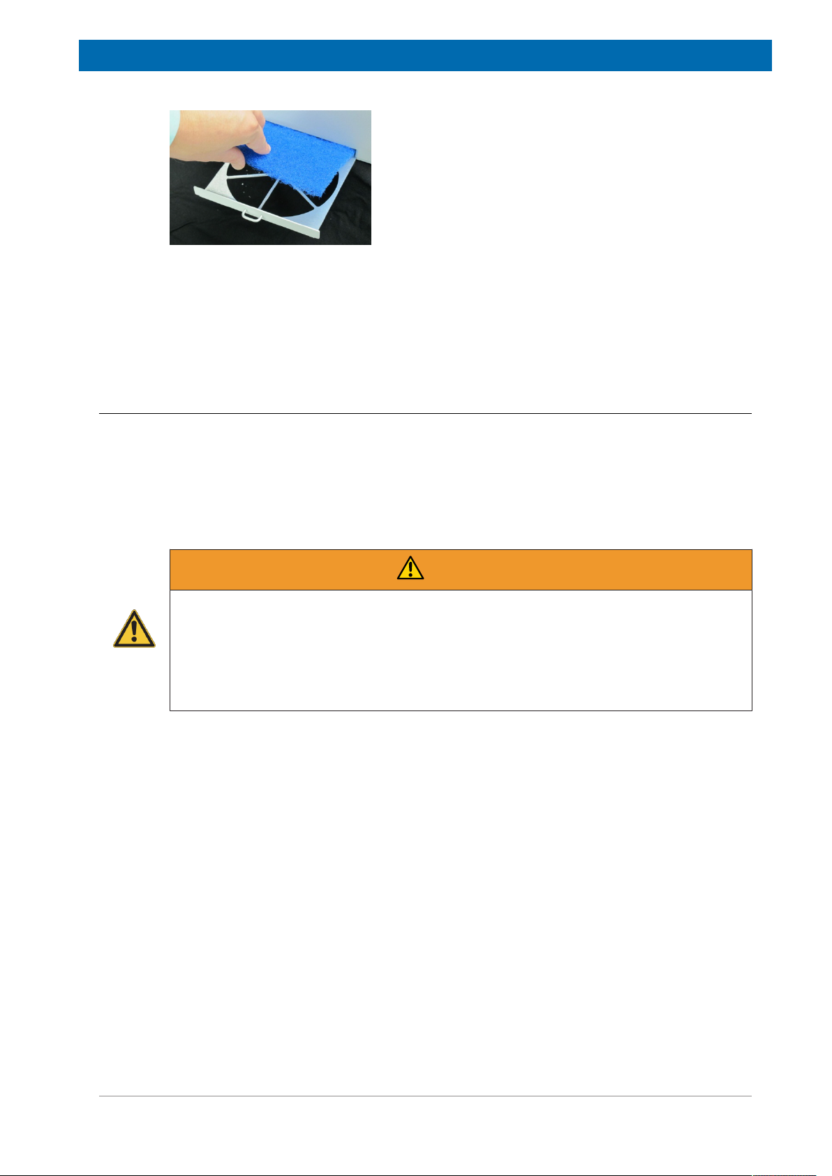
Figure8.4: Removing and Installing the Filter
• Install the new filter.
• Close the filter drawer.
• Turn the power back on.
8.3 Cleaning Instructions
To clean the exterior surfaces of the device, complete the following steps:
• Shut down and unplug the device.
• Wipe the exterior surfaces only using a towel dampened with a lab‑grade cleaning agent.
• Repeat the previous step, using a towel dampened with clear water.
• Dry the device exterior using a dry towel.
Maintenance
WARNING
Shock Hazard from Liquids
Liquid coming in contact with electrical components may result in a serious injury through
shock.
u Do not allow any liquid to enter the device cabinet other than as intended through the
specified tubing, or come into contact with any electrical components.
u The device must be thoroughly dry before you reconnect power, or turn the device on.
H148851_3_003
31

Maintenance
32 H148851_3_003

Dismantling and Disposal
9 Dismantling and Disposal
Following the end of its operational life, the device must be dismantled and disposed of in
accordance with the environmental regulations.
Installation, initial commissioning, retrofitting, repairs, adjustments or dismantling of the
device must only be carried out by Bruker Service or personnel authorized by Bruker.
Damage due to servicing that is not authorized by Bruker is not covered by your warranty.
9.1 Safety
WARNING
Danger of injury from electrical shock!
A life threatening shock may result when the housing is open during operation.
u Only qualified personnel should open the housing.
u Disconnect the device from the electrical power supply before opening the device. Use
a voltmeter to verify that the device is not under power!
u Be sure that the power supply cannot be reconnected without notice.
WARNING
Danger of injury due to improper dismantling!
Stored residual energy, angular components, points and edges on and in the device or on
the tools needed can cause injuries.
u Ensure sufficient space before starting work.
u Handle exposed, sharp-edged components with care.
u Dismantle the components properly.
u Secure components so that they cannot fall down or topple over.
u Consult the manufacturer if in doubt.
9.2 Dismantling
Before starting dismantling:
1. Shut down the device and secure to prevent restarting.
2. Disconnect the power supply from the device; discharge stored residual energy.
3. Remove consumables, auxiliary materials and other processing materials and dispose of
in accordance with the environmental regulations.
4. Clean assemblies and parts properly and dismantle in compliance with applicable local
occupational safety and environmental protection regulations.
H148851_3_003
33

Dismantling and Disposal
9.3 Disposal
After the lifespan of the product, Bruker takes responsibility for disassembly and disposal in
accordance with the European Directive WEEE 2012/19/EC. Bruker BioSpin will take back
the components free of charge upon request by the customer. If the customer wants to
arrange disposal on their own, then this must be stated when the product is ordered.
European Waste Electrical and Electronic Equipment Directive (WEEE 2012/19/EC)
Do not dispose in domestic household waste.
The affixed label indicates that it is prohibited to discard this electrical/electronic product in
domestic household waste, in compliance with the European Waste Electrical and Electronic
Equipment Directive (WEEE 2012/19/EC).
For instructions on how to return end-of-life equipment, producer-supplied electrical
accessories or auxiliary items for proper disposal contact the supplier or importer. If the
supplier cannot be reached, contact the manufacturer.
NOTICE
Danger to the environment from incorrect handling of pollutants!
Incorrect handling of pollutants, particularly incorrect waste disposal, may cause serious
damage to the environment.
u Always observe local environmental regulations regarding handling and disposal of
pollutants.
u Take the appropriate actions immediately if pollutants escape accidentally into the
environment. If in doubt, inform the responsible municipal authorities about the damage
and ask about the appropriate actions to be taken.
34 H148851_3_003

10 Contact
Manufacturer:
Bruker BioSpin GmbH
Am Silberstreifen
D-76287 Rheinstetten
Germany
Helpdesk Europe: (+49) 721-5161-6155
Helpdesk USA: (+1) 978-667-9580
Contact
E-Mail:
http://www.bruker.com
WEEE DE43181702
Bruker BioSpin Hotlines
Contact our Bruker BioSpin service centers.
Bruker BioSpin provides dedicated hotlines and service centers, so that our specialists can
respond as quickly as possible to all your service requests, applications questions, software
or technical needs.
Please select the service center or hotline you wish to contact from our list available at:
http://www.bruker.com/service/information-communication/helpdesk/magnetic-
resonance.html
minispec.SLS@bruker.com
H148851_3_003
35

Contact
36 H148851_3_003

List of Figures
List of Figures
Figure 2.1: The TC3 Unit. ............................................................................................................... 7
Figure 3.1: Bottom View with Filter Drawer Removed .................................................................... 10
Figure 4.1: Thermal Characteristics of a 3-Zone 10 mm SFC Version ........................................... 16
Figure 4.2: Thermal Characteristics of a 1-Zone 10 mm Polymers Version ................................... 17
Figure 4.3: Thermal Characteristics of a 2-Zone 26 mm Version ................................................... 17
Figure 6.1: Base of the Sample Changer........................................................................................ 22
Figure 6.2: Bottom of the Temperature Unit ................................................................................... 22
Figure 6.3: Optional Table Adapter................................................................................................. 23
Figure 6.4: Serial Cable Connected to the Back of the Sample Changer....................................... 23
Figure 6.5: Serial Connector on the Unit......................................................................................... 24
Figure 6.6: Power Connections for the Unit .................................................................................... 25
Figure 6.7: Nitrogen Connection for the Unit .................................................................................. 25
Figure 7.1: LEDs (for 10 mm SFC version with 3 zones)................................................................ 27
Figure 8.1: Fuse Holder for the TC3 ............................................................................................... 29
Figure 8.2: Fuse.............................................................................................................................. 30
Figure 8.3: Opening the Filter Drawer............................................................................................. 30
Figure 8.4: Removing and Installing the Filter ................................................................................ 31
H148851_3_003 37

List of Figures
38 H148851_3_003

List of Tables
List of Tables
Table 3.1: Explanation of Caution and Warning Notices .................................................................... 12
Table 4.1: Environmental Characteristics ........................................................................................... 15
Table 4.2: Electrical Characteristics.................................................................................................... 15
H148851_3_003 39

List of Tables
40 H148851_3_003

Index
Index
P
pollution degree................................................15
power cord..........................................................9
A
Air filter .............................................................30
avis Canadien...................................................13
C
cleaning ............................................................31
condensation
humidity .......................................................19
D
Disassembly .....................................................34
disposal ............................................................34
E
Electrical characteristics...................................15
F
FCC notice .......................................................13
Filter..................................................................30
Fuse ...........................................................24, 29
R
Regulatory notices..............................................9
S
Safety information ..............................................9
T
Table adapter ...................................................23
Temperature
Operating.....................................................15
Temperature range...........................................16
Tubing
kinks ............................................................19
V
Voltage selection ..............................................24
W
WEEE notice ....................................................34
H
Humidity ...............................................11, 15, 19
I
ICES 001 ..........................................................13
intended use.......................................................8
interference ......................................................13
L
Lamps
LEDs............................................................27
LEDs.................................................................27
lifting instructions..................................10, 19, 21
M
mains disconnect................................................9
N
Nitrogen supply ................................................25
H148851_3_003
41

Index
42 H148851_3_003

H148851_3_003 43

Bruker Corporation
●
info@bruker.com
www.bruker.com
Order No: H148851
 Loading...