

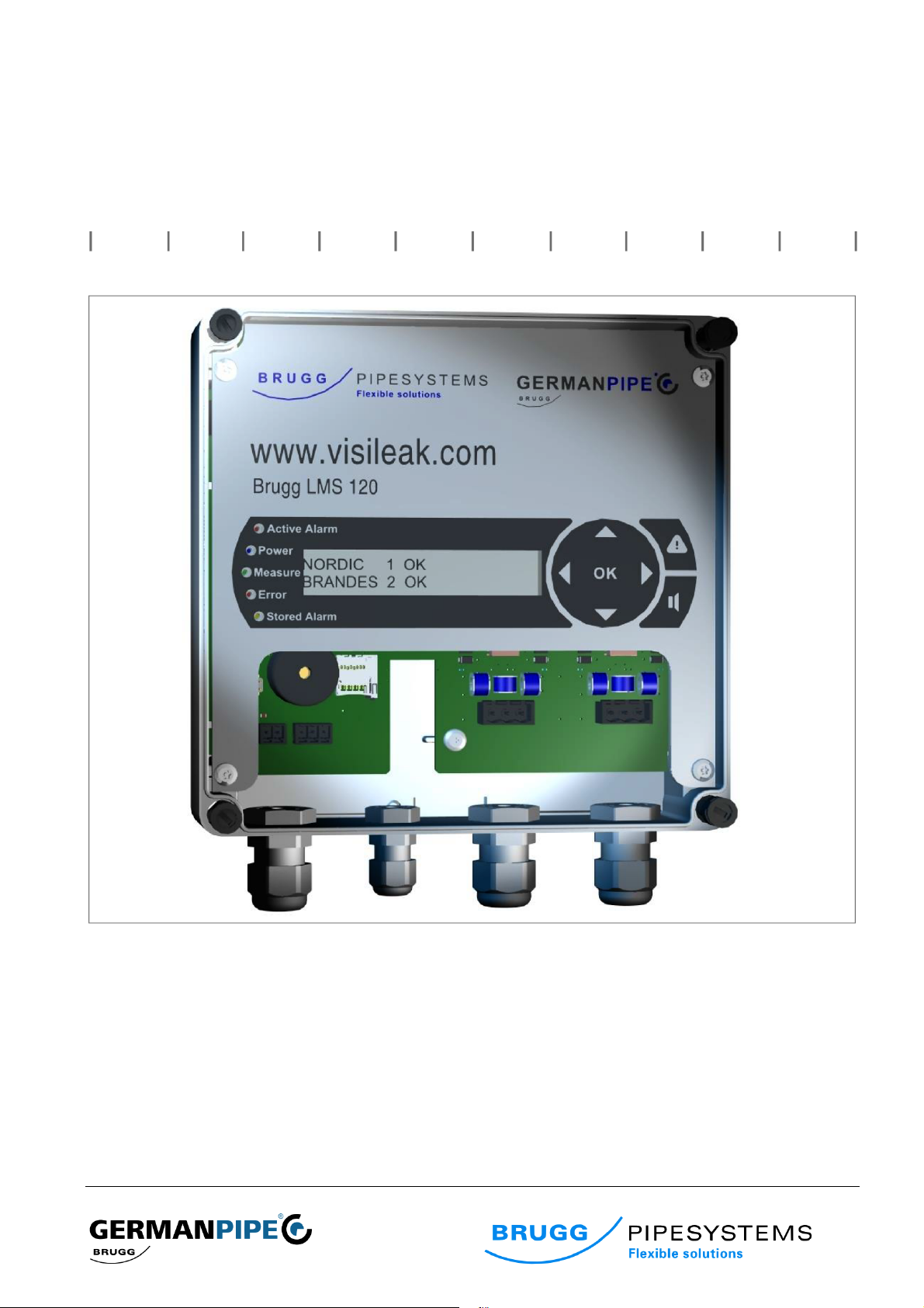
Brugg LMS 120 monitoring device
Operating and service instructions
Art.-Nr.: 1010368

Operating and service instructions | LMS 120 2
Contents
1.! Scope of delivery .............................................................................................................................................. 4!
2.! General ............................................................................................................................................................... 4!
2.1. System design ................................................................................................................................................. 4!
3.! Installation ......................................................................................................................................................... 5!
3.1. Mechanical installation ..................................................................................................................................... 5!
3.2. Electrical connection ........................................................................................................................................ 6!
4.! Operation ........................................................................................................................................................... 7!
4.1. Display and operating elements ...................................................................................................................... 7!
4.2. Operation menu ............................................................................................................................................... 8!
4.3. Quick parameter setting ................................................................................................................................... 9!
4.4. Enhanced parameter setting .......................................................................................................................... 10!
4.5. Alarm menu ................................................................................................................................................... 13!
4.6. Manual measurement .................................................................................................................................... 14!
4.7. Firmware update ............................................................................................................................................ 14!
5.! Maintenance .................................................................................................................................................... 15!
6.! Service ............................................................................................................................................................. 15!
6.1. System code .................................................................................................................................................. 15!
6.2. Fault record .................................................................................................................................................... 16!
Tab. 5 (Fault record)7.! Accessories ................................................................................................................... 16!
8.! Technical data ................................................................................................................................................. 17!
9.! Glossary, terms ............................................................................................................................................... 18!
10.! Notes ................................................................................................................................................................ 19!
Operating and service instructions | LMS 120 3
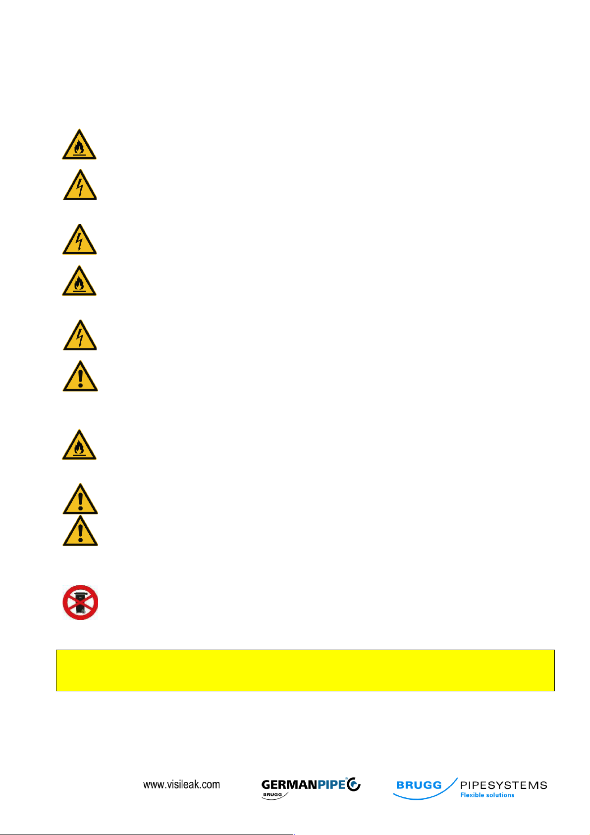
Safety notes
The following points must be observed for safety during connecting and operating the device. Read the notes
carefully before commissioning the device. The installer is responsible for any damage caused by improper use or
application of the device.
Mains
voltage
Operate the device only with the mains voltage intended (see 8. Technical data;
page 17). The device may only be connected to the mains once all connections
have been established. There is a risk of fire in the event of incorrect mains voltage.
Mains cable
It must be ensured that the mains cable is not damaged. Devices with damaged
mains cables must be disconnected from the mains (disconnect the mains plug)
and made secure before re-commissioning. There is a danger to life from electric
shock.
Earthing
The device must be earthed as required by regulations or connected to a suitable
potential equalisation. The DIN VDE 100 and the country-specific regulations must
be observed. There is a risk of excess voltage.
Place of
installation
Protect the device from humidity, dripping and spray water. Do not place any
objects on the device. Do not install the device near strong sources of heat. Do not
expose it to direct sunlight.
There is a risk of fire.
Cleaning
Disconnect the mains plug before cleaning the device. Use a dry cloth for cleaning
and clean the surface only. There is a danger to life from electric shock when
coming into contact with parts inside the device.
Connections
Incorrect wiring of the connections may result in faults or defective devices. The
manufacturer accepts no liability for accidents that are caused by incorrectly
installed or improperly maintained devices. The manufacturer accepts no liability
whatsoever if the system is incorrectly used or programmed in a way that is not
safe.
Ventilation
The heat created in the device is dispersed sufficiently. Do not install the device in a
cabinet with insufficient heat extraction or near sources of heat. (see 3.1.
Mechanical installation and 3.2. Electrical connection; from page 5). There is a risk
of fire.
Operation
Correct operation requires that the transparent front lid of the LMS 120 is closed to
ensure protection category IP65.
Repairs
Installation, modification, repairs or maintenance must be carried out in accordance
with the regulations of the manufacturer. Any disassembly and repair attempts
without the manufacturer’s approval result in the warranty claim becoming null and
void. Tampering with the device may put the electric safety of the device at risk.
The manufacturer is not liable for accidents of the user on the open device.
Electronic devices should not be disposed of with domestic waste. They must be disposed of in
accordance with the country-specific directives. Please discard this device at the intended collection
points for disposal when no longer in use. For discarded electric and electronic devices, Directive
2002/96/EC of 27 January 2003 applies in the European Union.
When conducting welding work on the district heating pipeline, the LMS 120 MUST be deactivated and
the measuring lines MUST be disconnected. Otherwise, the LMS 120 and other connected devices may
be damaged.

Operating and service instructions | LMS 120 4
1. Scope of delivery
• LMS 120 monitoring device with pre-installed mains cable
• Plug connector - insert for alarm terminal
• Plug connector - inserts for monitoring channels 1 and 2 terminals
• Operating instructions
• Drilling template
2. General
The LMS 120 is suitable for monitoring two sensor wires in district heating pipelines. These may be executed in accordance with the
NORDIC or BRANDES system. The so-called SWISS system corresponds to the Nordic system with one isolated conductor.
The technical design allows monitoring of two different system types at the same time. As such, it is possible to connect one line with the
NORDIC system on measurement channel 1 and one line with the BRANDES system on measurement channel 2, for instance.
The system is based on measuring resistances between monitoring conductors and the metal medium pipe or the resistances of
measurement loops. All measured values can be read from the display.
(see 4.2. Operation menu; page 8)
2.1. System design
The LMS 120 has measurement channels operating free of potential to increase measurement precision and minimise the influence of
parasitic current measurements in the pipe.
Fig. 1 (System design)
Sensor
Return
Sensor
Return
Relay
Display
Keys
CPU
Measurement
module
1
Measurement
module
2
Pipe
Pipe

Operating and service instructions | LMS 120 5
The current status and the measurements can be read from the display. The 5 LEDs to the left of the display
provide a quick overview of the current device status.
Fig. 2 (View of device)
3. Installation
3.1. Mechanical installation
The mechanical installation of the LMS 120 monitoring device
can be carried out on an even dry wall (drilling template) or
alternatively in a control cabinet.
At the place of installation, the device must be protected
against humidity (formation of condensation), strong dust and
strong electromagnetic fields. The safety notes, protection
measures and notes stated in these operating instructions
must be observed (see Safety notes; page 3). The housing lid
must be removed for fastening.
The installation must be carried out with fasteners that are
suitable for the respective substrate.
Fig. 3 (Wall installation)
Display
LEDs
Alarm contact
Voltage 2 (12v)
Alarm menu key
Cursor keys
Alarm off key
Terminal - channel 2
Terminal - channel 1

Operating and service instructions | LMS 120 6
3.2. Electrical connection
3.2.1. Connection terminals
Terminal
Description
12V
+
-
12V +
12V -
Low voltage
(optional)
Alarm
NO
COM
NC
Make cont’t
Root
Break cont’t
External fault
message
Channel 1
S1
Pipe
S2
Sensor
Pipe
Return
conductor
Channel 1
Channel 2
S1
Pipe
S2
Sensor
Pipe
Return
conductor
Channel 2
Tab. 1 (Terminals)
Note:
The 12V terminal is reserved for a special
version of the LMS 120. It must not be used.
The Alarm terminal can be charged with an
ohmic load of up to 2A/ 30V.
Fig. 4 (Wiring diagram)
3.2.2. Earth connection
To ensure smooth operation, the earth contact (pipe) of every measurement circuit must be connected with the
associated pipeline. When replacing existing leakage measurement systems, it is mandatory to check whether an
effective earth connection to the relevant pipe exists. Each measurement channel requires its own connection with
the pipeline.
3.2.3. Power
Finally, the device plug has to be inserted into a socket. The LMS 120 can be operated with an alternating current
of 90…240 V AC.
3.2.4. Commissioning
After the mechanical and electrical installation, the LMS 120 parameters need to be set. The procedure is
described in Section 4.3. Quick parameter setting on page 9.

Operating and service instructions | LMS 120 7
4. Operation
The LMS 120 displays information in various menus in a clear manner. 7 keys, 5 status displays (LED) and one
clear text display are arranged on the front plate. The current measurement values can be called up and operating
data set with the keys. The status displays (LED) provide a quick overview of the status of the line connected.
All detailed information and the parameter setting menus are shown by the info display.
4.1. Display and operating elements
Description
Symbol
Description
Cursor keys:
Left / right in the menu
Up / down in the menu
Confirmation, OK
Alarm menu
Open alarm menu
Deactivate acoustic signalling
Deactivate acoustic signalling
Display operating voltage
LED blue in the event of voltage
Measurement display operating
LED flashing green during ongoing
measurement
Error display
LED red in the event of device fault
Limit/s exceeded display
LED red in the event of exceeded limit
Stored alarms display
LED orange in the event of stored alarms
Tab. 2 (Display and operation)

Operating and service instructions | LMS 120 8
4.2. Operation menu
Operation displays 1 to 4 provide a complete overview of the status of the monitoring loops and the device status.
The individual displays can be selected with the following keys:
Fig. 5 (Operation
menu)
Operation display 1:
In this view, the type, channel number and the status of the monitoring loops are displayed.
Possible displays are:
System type NORDIC, BRANDES, SWISS, OFF
Channel 1, 2
Status OK, Alarm Loop, Alarm Iso., Alarm I&L
Operation display 2:
The values of the last measurement are displayed here.
Explanation:
I: Isolation value (measure of dampness of thermal
isolation)
L: Loop resistance (monitoring loop verification)
Operation display 3:
This display is only needed for service purposes. The data must be entered into the record of the fault report. (see
6. Service; page 15)
Operation display 4:
The serial number and device version are displayed here. The data must be entered into the record of the fault
report. (see 6. Service; page 15)
Operation display 1
Operation display 2
Operation display 3
Operation display 4
or
Operating and service instructions | LMS 120 9
4.3. Quick parameter setting
The quick parameter setting function applies practical values for all parameters depending on the monitoring
system. This procedure is sufficient to commission the LMS 100 in full.
System defaults:
Nordic
Brandes
Swiss
Device defaults
Standard
Isolation limit
Measure cycle
1 h
Loop limit
200 Ω
6.0 kΩ
200 Ω
Horn
On
Tolerance
- - -
Tab. 3 (Default values)
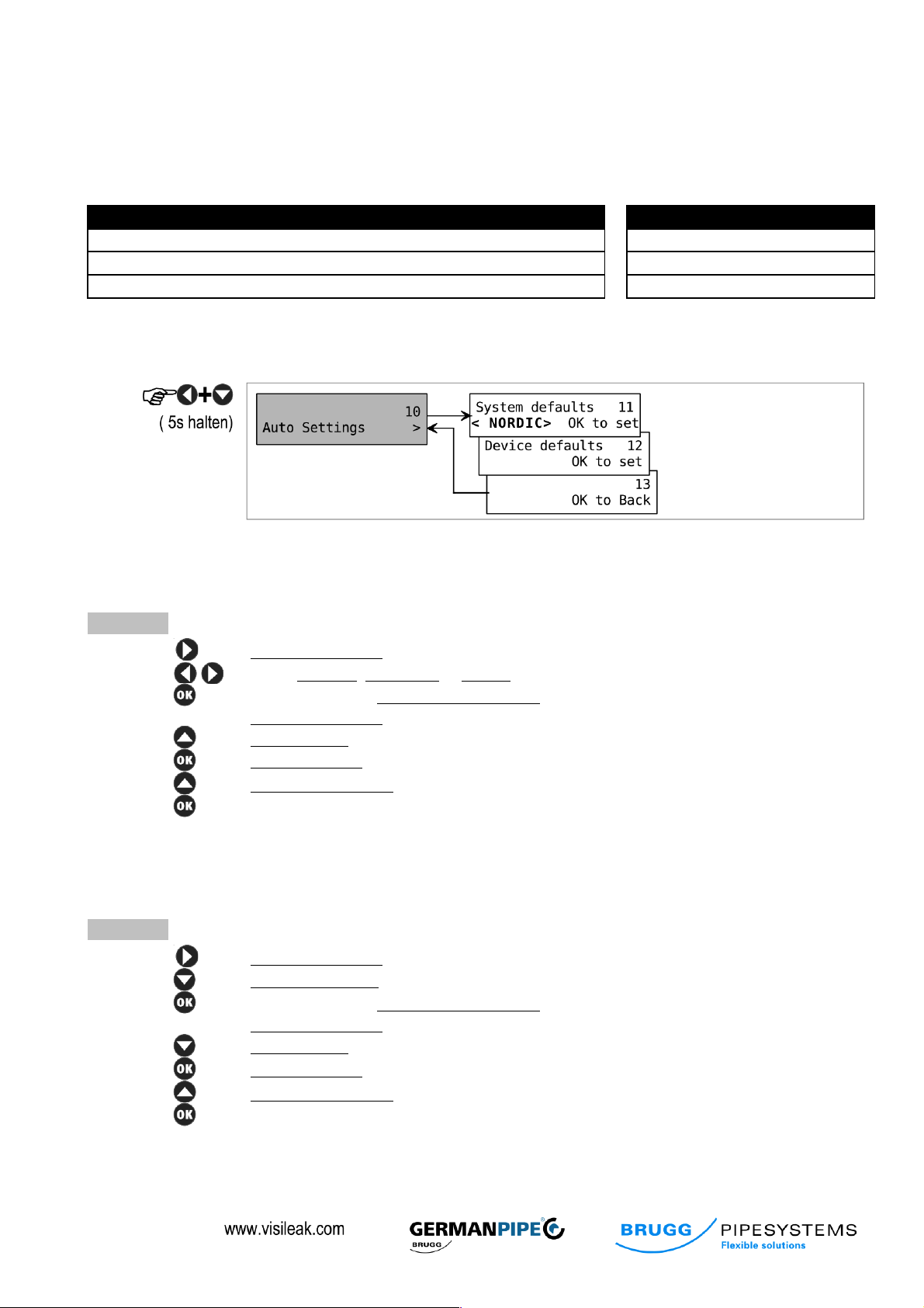
4.3.1. Activating the service menu
To adopt these values, the service menu has to be activated as follows:
Fig. 6 (Auto settings)
4.3.2. Setting NORDIC, BRANDES or SWISS
After activating the service menu (see 4.3.1.), perform the following steps.
Procedure:
1. System Defaults 11 is displayed
2. Select NORDIC, BRANDES or SWISS
3. Confirm selection, Setting channel defaults is displayed briefly, then again
System Defaults 11
4. OK to Back 13 is displayed
5. Auto Settings 10 is displayed
6. OK to Save & Exit 90 is displayed
7. Operation display 1 appears
4.3.3. Setting device to default
After activating the service menu (see 4.3.1.), perform the following steps.
Procedure:
1. System Defaults 11 is displayed
2. Device Defaults 12 is displayed
3. Confirm selection, Setting channel defaults is displayed briefly, then again
System Defaults 12
4. OK to Back 13 is displayed
5. Auto Settings 10 is displayed
6. OK to Save & Exit 90 is displayed
7. Operation display 1 appears

Operating and service instructions | LMS 120 10
4.4. Enhanced parameter setting
All parameters to be monitored can be defined individually in this menu. This procedure should be chosen when
the default values described under Section 4.3. Quick parameter setting on page 9 are not suitable or when the
limits should be or have to be modified. This multi-step menu is arranged on two levels where the desired settings
can be made with the cursor keys (7).
To enter the Configuration menu, please press the following key combination:
Fig. 7 (Settings)
Use the keys for navigation and selection and the key to confirm.
Level 1 menu
Level 2 menu
Settings
(hold down

Operating and service instructions | LMS 120 11
4.4.1. Auto settings
Menu item 11 sets default values depending on the type of monitoring system. Under menu item 12, the device
parameters are reset to factory settings. An overview of the default values can be found in Table 3 on page 9.
4.4.2. Channel settings
The type of the monitoring system is selected in menu items 21 and 31. Following this selection the limits for
isolation and loop monitoring are limited to sensible levels.
Isolation alarm - menu 22/ 32
The limit for triggering an alarm can be set with the keys. If the
measurement for the isolation resistance falls below the limit, the LMS 120
switches to alarm.
Possible settings:
NORDIC/ SWISS/ BRANDES: 10 kΩ … 20 MΩ
Loop alarm - menu 23/ 33
The limit for triggering an alarm can be set with the keys. If the
measurement for the loop resistance exceeds the limit, the LMS 120 switches
to alarm.
Possible settings:
NORDIC/ SWISS: 200Ω, 300Ω, 500Ω
BRANDES: 1 kΩ … 19 kΩ
Tolerance alarm - menu 24/ 34
The tolerance for triggering an alarm can be set with the keys. It is
selected in percent of the limit for the loop resistance.
If the measurement for the loop resistance exceeds or falls below the range,
the LMS 120 switches to alarm.
Possible settings:
NORDIC/ SWISS: not available
BRANDES: above limit, 10% ... 50%
When above limit, only the top limit has effect, which is determined by menus 23 and 33.
Example;
Loop limit: 4.0 kΩ
Tolerance: 10%
Bottom limit: 3.6 kΩ
Top limit: 4.4 kΩ
If the measurement falls below 4.4 kΩ or if it falls below 3.6 kΩ, the LMS 120 switches to alarm.

Operating and service instructions | LMS 120 12
4.4.3. Device settings
Devices settings are settings that relate to the general functions of the LMS 120. The menu structure is displayed in
Fig. 7 on page 10.
Measure cycle - menu 41
The measure cycle of the fully automatic measurement is set here. In the event of an alarm message, the duration
of the fault can be assessed by multiplying the measure cycle with the number of errors saved. (see 4.5. Alarm
menu; page 13)
Example;
Measure cycle: 6 h
Error number: (092)
Fault since: 92 x 6 h = 552 h = 23 days
Possible settings: 2min, … , 30min, 1h, … 24h
Buzzer - menu 42
The LMS 120 issues an acoustic signal in the event of faults in the monitoring system. This signal can be
deactivated.
Possible settings: On, Off
Self-test - menu 43
The LMS 120 conducts a self-test after every start. If it is suspected that the LMS 120 is not working correctly, a
manual self-test should be started. To this end, the key in the Self-test menu has to be pressed.
The following message is shown in the display after successfully completing the self-test.

Operating and service instructions | LMS 120 13
4.5. Alarm menu
The LMS 120 has a non-volatile alarm log (the errors are not lost from the alarm log in the event of a power cut).
Fault messages can therefore be identified even if they are no longer current during the device inspection. To enter
the Alarm menu, please press the Alarm menu key (6).
Browse the menu with Fig.8 (Alarm menu)
Alarm menu 01 and Alarm menu 03:
The status and the number of faults of the sensor loop are shown in this display.
Possible displays are:
No Alarms
Active Alarms
Old Alarms
Alarm menu 02 and Alarm menu 04:
The status and the number of faults of the isolation resistance are shown in this display.
Possible displays are:
No Alarms
Active Alarms
Old Alarms
Alarm menu 05:
is used to clear the alarm log and to set all counters to 000.
Alarm menu 06:
is used to exit the alarm menu.
When active errors are displayed, it is possible to estimate how long the error has already been pending with the
use of the cycle set in the measure cycle and the number of stored errors. In the event of a fault message, please
fill in and send the record (see 6.2. Fault record; page 16) to the e-mail address alarm@visileak.com. The fault
message can also be sent online at www.visileak.com.
Alarm log channel 1 - loop
Alarm log channel 1 - isolation
Alarm log channel 2 - loop
Alarm log channel 2 - isolation
Clear alarm log
Exit alarm log

Operating and service instructions | LMS 120 14
4.6. Manual measurement
Regardless of the periodic, automatic measurements, a manual measurement can also be triggered where
required. This is helpful during the installation or after a modification of the system (e.g. grid expansion). Press the
following key to activate the manual measurement:
(hold down for 5 sec)
The measurement starts as soon as the LED starts to flash. At the end of the process, the LED
goes out and operation menu 1 is displayed.
4.7. Firmware update
New functions can be incorporated by updating the
software of the LMS 120. An appropriately prepared
micro SD card is required for this purpose.
Procedure:
1. Disconnect the LMS 120 from the mains
2. Insert micro SD card
3. Connect the LMS 120 with the mains
4. Wait until operation menu 1 appears
Fig. 1 (Firmware update)

Operating and service instructions | LMS 120 15
5. Maintenance
The LMS 120 is a maintenance-free monitoring device and does not need periodic maintenance or inspection. As
part of a district heating maintenance programme inspections should be carried out at least once a month.
The and displays indicate any errors. If one of these displays lights up, the
measurement values should be inspected.
The record from Section 6.2. Fault record on page 16 should be used for a service report.
6. Service
In the operation menu, display 3 provides coded information on the setting and measurement values of the LMS
120 (see 4.2. Operation menu; page 8). It offers the service technician a quick overview and is helpful for finding
errors. It is used for the error report.
6.1. System code
N 1 1 0 0 5 0 0 1 7 4 1 2 0 0 2 0 0 1 - B 2 1 2 0 0 0 0 9 9 9 9 9 0 6 0 0 9 3
5
1 2 3 4 5 6 7 8 9
10
11
12
13
14
15
16
17
18
19
20
System / channel
Channel 1=on, 0=off
Isolation limit
[kΩ]
Isolation measurement
[kΩ]
Loop limit display x 100 = limit in
[Ω]
Loop measurement display x 100
= limit in
[Ω]
Tolerance / x 10 = limit in
[%]
Tab. 4 (System code)
Operating and service instructions | LMS 120 16
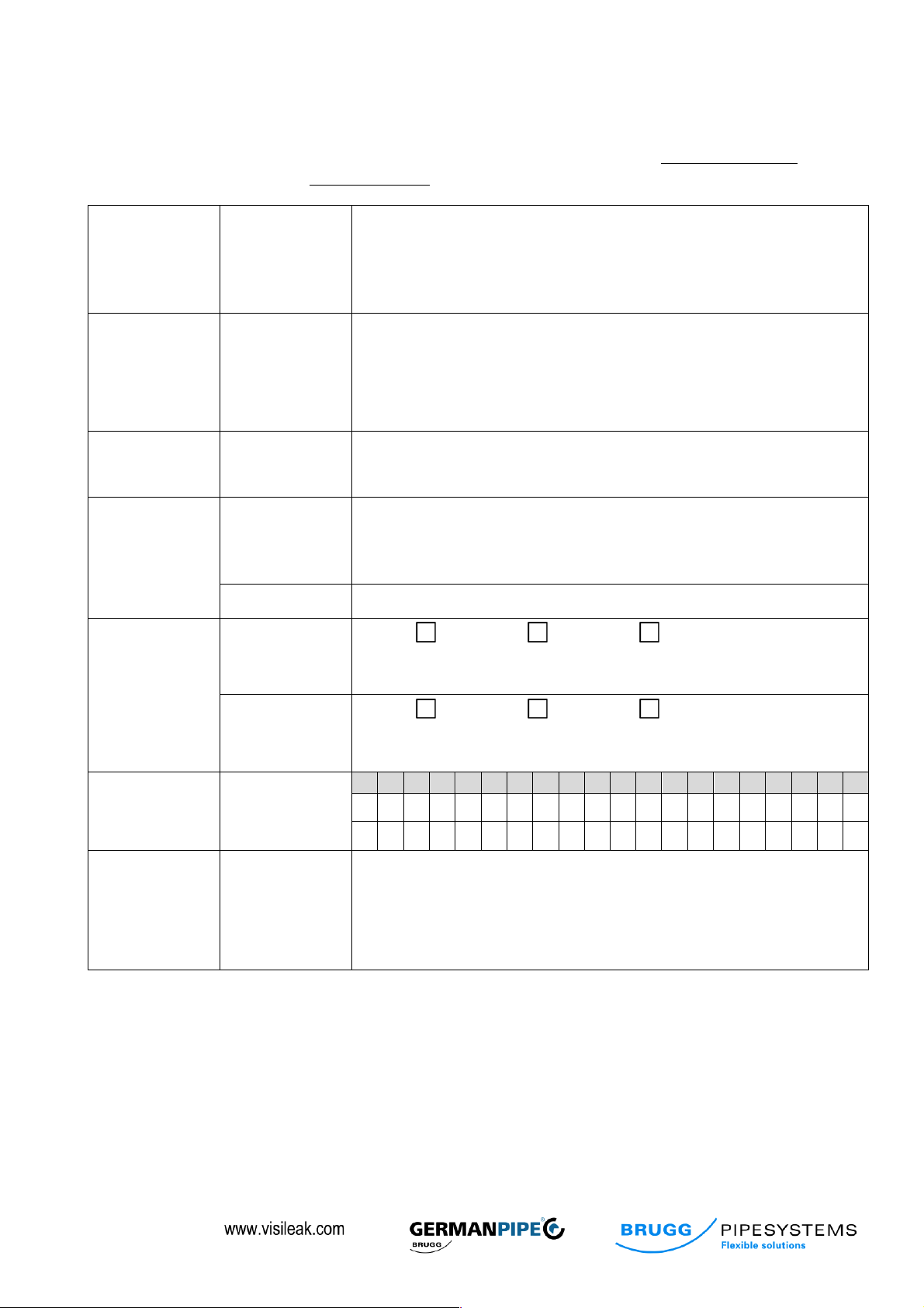
6.2. Fault record
In the event of a fault, please fill in the fault record and send it to the e-mail address alarm@visileak.com. The fault
report can also be sent online at www.visileak.com.
Customer:
Company
Name
Address
Country
Telephone
Building/
property:
Name
Address
Note:
Error:
Description
Error since:
Measured
values
Loop 1
Type: Nordic Brandes Swiss
Isolation:............................. Loop: :..............................
Loop 2
Type: Nordic Brandes Swiss
Isolation:............................. Loop: :..............................
Service code:
See 4.2.
1 2 3 4 5 6 7 8 9
10
11
12
13
14
15
16
17
18
19
20
Date:
Signature:
Tab. 5 (Fault record)

Operating and service instructions | LMS 120 17
7. Accessories
Item name
Item number
Description
LMS 120 DE
21000076
LMS 120 with mains plug for Germany
LMS 120 CH
LMS 120 with mains plug for Switzerland
Socket AD2
21000083
Socket for LMS 120
Monitoring end piece
21000081
Loop end plug
Tab. 6
(Accessories)
8. Technical data
Requirements for voltage supply
Voltage
100 – 240 VAC
Power consumption
max. 100 mA
Max. power consumption on
activation
6 A
Output
6 W
Housing specification:
Dimensions (width x height x depth)
182 x 180 x 90 mm
Installation
Wall instillation, control cabinet installation, screws
Materials and colour
Housing: Polystyrene, grey (similar to RAL 7035)
Lid: Polycarbonate, transparent
Protection category
IP 65 in accordance with EN 60529
Weight (excl. packaging)
1.1 kg
Measurement inputs specification:
Wire standards / measurement
wires
Nordic, 2 copper blank
Brandes, NiCr 5,7 Ω/m copper isolated
Swiss, copper blank – copper isolated
Potential separation
Yes
Alarm output specification
Type of the alarm output:
Relay
Max. contact voltage:
30 VDC
Max. switching current:
2 A
Min. switching current:
1 mA (at 10 mVDC)
Ambient conditions
Ambient temperature
0 to + 50° C
Transport and storage temperature
-20 to + 60° C
Humidity:
< 90 %, not condensing
Tests and certificates
EC Declaration of Conformity
Yes
Conformity standards
EN 61000-6-2 (2006-05-01)
EN 61000-6-4 (01/11/2007)

Operating and service instructions | LMS 120 18
Tab. 7 (Technical
data)
9. Glossary, terms
Device display
Meaning
Device display
Meaning
above Limit
above limit
Measure
Messung
Active alarm
aktuelle Alarmmeldung
Measure Cycle
Measure cycle
Alarm
Alarmmeldung
No
kein
Alarm Iso
Alarm Isolationsfehler
Off
Aus
Alarm Loop
Alarm Schleifenfehler
On
On
Alarm I&L
Alarm Isolations- und
Schleifenfehler
Pass
durchgeführt
Auto
Automatisch
Pipe
Rohr
Back
zurück
Power
Netzspannung
Buzzer
Signalhupe
Save
sichern
Channel
Kanal
Self Test
Selbsttest
Clear Alarms
Lösche Alarme
Setting
Einstellung
Default
Grundeinstellung
Stored Alarm
gespeicherte
Alarmmeldung
Device
Gerät
System
System
Error
Gerätefehler
Tolerance
Toleranz
Exit
Ausgang, Verlassen
wait
warten
Isolation
Isolation
Tab. 8 (terms)
Log
Speicher
Loop
Schleife
- Subject to technical changes. –

Operating and service instructions | LMS 120 19
10. Notes
....................................................................................................................................................................................
....................................................................................................................................................................................
....................................................................................................................................................................................
....................................................................................................................................................................................
....................................................................................................................................................................................
....................................................................................................................................................................................
....................................................................................................................................................................................
....................................................................................................................................................................................
....................................................................................................................................................................................
....................................................................................................................................................................................
....................................................................................................................................................................................
....................................................................................................................................................................................
....................................................................................................................................................................................
....................................................................................................................................................................................
....................................................................................................................................................................................
....................................................................................................................................................................................
....................................................................................................................................................................................
....................................................................................................................................................................................
....................................................................................................................................................................................
....................................................................................................................................................................................
....................................................................................................................................................................................

2013-11-01 Rev.D
Brugg Rohrsystem AG
Industriestrasse 39
CH-5314 Kleindöttingen
phone +41 (56) 268 78 78
fax +41 (56) 268 78 79
www.pipesystems.com
BRUGG Rohrsysteme GmbH
Adolf-Oesterheld-Straße 31
D-31515 Wunstorf
phone +49 (5031) 170-0
fax +49 (5031) 170-170
www.brugg.de
GERMAN PIPE
Industrie- und Fernwärmetechnik GmbH
Darrweg 43
D-99734 Nordhausen
phone +49 (36 31) 46 26 7 - 0
fax +49 (36 31) 46 26 7 - 79
www.german-pipe.de
 Loading...